1
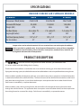
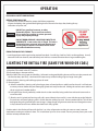
Installation
INDOOR SOLID FUEL FURNACE
Models: 8095, 8130, 8130HD
www.royallfurnace.com
325 South Park Street, Reedsburg, WI 53959
Phone 608-768-8508
Thank you for purchasing a ROYALL Indoor Forced Air Solid Fuel Furnace.
is a quality Indoor Solid Fuel Appliance designed to effectively heat structures.
Please read and follow all safety instructions to ensure optimal performance and safety.
The installation and operation of the
is quite simple. Nevertheless, we recommend
installation to be completed by a qualified professional. The installation and operational
instructions should be carefully read and followed. Pay particular attention to the chimney and
chimney connector installation as they can present a significant fire danger. Refer to appliance
markings for additional instructions.
If you have any questions on the installation or operation of your Indoor Solid Fuel Appliance,
please contact your local
representative.
HAZARD DEFINITIONS
OBSERVE AND FOLLOW ALL SAFETY INSTRUCTIONS
The following defined terms are used throughout this manual to bring attention to the presence of hazards of serious
risk levels, or important information concerning the life of the product. Failure to install properly or failure to follow
safety instructions could result in severe personal injury, death or substantial property damage.
DANGER
Indictates presence of hazards that WILL CAUSE SERVE personal injury, death or substantial property damage.
WARNING
Indicates presence of hazards that CAN CAUSE SERVE personal injury, death or substantial property damage.
CAUTION
Indicates presence of hazards that WILL OR CAN CAUSE minor personal injury or property damage.
NOTICE
Indicates special instructions on installation, operation or maintenance that are important but not related
to personal injury or property damage.
VERIFY WITH YOUR INSURANCE COMPANY AND ALL LOCAL CODES AND ORDINANCES PRIOR TO INSTALLATION.
IT IS THE OWNER’S RESPONSIBILITY TO ENSURE THAT THE APPLIANCE MEETS ALL LOCAL CODES AND ORDINANCES.
Page
2
November 2013
PRODUCT REGISTRATION CARD
Warranty is in effect from the date of purchase upon receipt of this card.
NAME
STREET ADDRESS
CITY
STATE
ZIP CODE
PHONE
E-MAIL ADDRESS
DATE OF PURCHASE
MODEL NUMBER
SERIAL NUMBER
DEALER
CITY
STATE
Reason for choosing Royall over other brands
__Price __Features __Safety __Previously owned Royall __Recommended to you
__Other
OWNER’S REGISTRATION CARD MUST BE COMPLETED AND RETURNED T0 ROYALL AT TIME OF INSTALLATION.
Place
Stamp
Here
Brand Products
325 South Park Street
Reedsburg, WI 53959
Place
Stamp
Here
Brand Products
325 South Park Street
Reedsburg, WI 53959
CONTENT
GENERAL
SAFETY.................................................................................................................................................. Pg
4
SPECIFICATIONS................................................................................................................................. Pg
5
PRODUCT DESCRIPTION................................................................................................................... Pg
5-6
INSTALLATION
INSTALLATION PLACEMENT.............................................................................................................. Pg
6-7
CLEARANCES....................................................................................................................................... Pg
8
INSPECTING CONTENTS.................................................................................................................... Pg
9
FIREBRICK INSTALLATION................................................................................................................. Pg
10
INSTALLATION OF SHROUD.............................................................................................................. Pg
11
INSTALLATION WITH AN EXISTING FURNACE (SERIES)................................................................ Pg
12
FILTER BOX (OPTIONAL).................................................................................................................... Pg
13
TYPICAL SYSTEM SCHEMATICS........................................................................................................ Pg
14-15
VENTING ASSEMBLY........................................................................................................................... Pg
16-17
COMPONENT ASSEMBLY INSTALLATION........................................................................................ Pg
18
ELECTRICAL INSTALLATION.............................................................................................................. Pg
19-22
OPERATION
LIGHTING THE INITIAL FIRE.............................................................................................................. Pg
23
SETTING THE FAN LIMIT CONTROL................................................................................................. Pg
24
SETTING THE DAFT DAMPER........................................................................................................... Pg
24
BURNING.............................................................................................................................................. Pg
25-27
EMERGENCY ACTIONS....................................................................................................................... Pg
28
MAINTENANCE.................................................................................................................................... Pg
29-30
TROUBLE SHOOTING................................................................................................................................... Pg
31-32
REPLACEMENT PARTS LISTING................................................................................................................ Pg
33-36
WARRANTY.................................................................................................................................................... Pg
37
November 2013
Page 3
SAFETY
ALL STATE or LOCAL CODES take precedence and MUST be observed.
These models have been constructed along U L391-99 parameters. Many of the recommendations
in this manual are also based on the National Fire Protection Association Code 211.
Before installing or starting operation, read and familiarize yourself with all instructions.
NOTE:
Installation is to be performed only by qualified heating professionals.
RISK OF EXPLOSION OR PERSONAL INJURY WHEN FUEL DOOR OR ASH DOOR ARE OPENED:
DANGER
ALWAYS hesitate momentarily between the first and second latches when opening doors to allow
unburned gases to ignite. Failure to do so could result in severe burns.
DO NOT use chemicals, kerosene or other flammable liquids to start a fire; severe burns could result.
DO NOT store combustible liquids or materials near the appliance.
DO NOT store wood within the minimum clearance to combustibles.
DO NOT burn gasoline, naphtha or engine oil.
DO NOT start a fire if flammable vapors or dust are present. An explosion could result.
DO NOT install in garage where fuels are stored.
DO NOT burn garbage, tires, telephone poles, railroad ties or yard waste. In many areas this is illegal
and will damage the appliance. Burning anything other than approved fuels will void
any warranties.
MAINTENANCE:
To avoid electric shock, disconnect electrical supply before performing maintenance. To avoid severe burns,
allow the appliance to cool before performing maintenance.
APPLIANCE OPERATION:
DO NOT block flow of combustion or ventilation air to the appliance.
DO NOT restrict access to the rear of the unit for maintenance.
This appliance requires electricity whenever in operation. Operation without electricity could result in the
appliance overheating. If power outages are anticipated, a back-up electrical generator is recommended.
Page
4
November 2013
SPECIFICATIONS
INDOOR FORCED AIR FURNACE MODELS
Features
Dimensions: WxLxH (Inches)
Estimated BTU Output
Weight (LBS)
Fire Box Volume
Log Length (Inches)
Fuel Door Opening (Inches)
Flu Size (Inches)
NOTE:
8095
8130
8130HD
22x32x38
95,000
475
5.6 cubic ft.
26”
10” x 14”
8”
24x32x48
130,000
565
7.4 cubic ft.
26”
10” x 14”
8”
24x32x48
150,000
595
7.4 cubic ft.
26”
10” x 14”
8”
Output values are based on theoretical 12 hour sustained burn rate under optimal conditions
and are provided as guideline only. Actual output will depend on a variety of factors beyond the
manufacturer’s control including: furnace location, wood species, wood moisture, wood size, ash
management and combustion air temperature.
PRODUCT DESCRIPTION
The
Solid Fuel Furnace is designed to burn either seasoned, split cordwood or coal.
It is to be installed inside the building that it is heating.
The furnace can be installed as a stand-alone unit or can tie into an existing gas, oil or electric furnace System.
If tying into an existing system, the solid fuel furnace can be installed either in series or in parallel with the existing furnace.
When installed in parallel with the existing furnace, a new cold air return duct is routed to a circulation blower that
is attached to the back of the solid fuel furnace. The hot air duct out of the solid fuel furnace attaches to the hot air
duct above the existing furnace. A pair of back draft dampers are required at the hot air outlet of each furnace.
Each furnace is controlled by a separate thermostat.
When installed in series with an existing furnace, the cold air flows first through the existing furnace and then
through the solid fuel furnace. This application does not require a second circulation blower, but does require that
the existing furnace be a counter flow design. Each furnace is controlled by a separate thermostat.
November 2013
Page
5
PRODUCT DESCRIPTION (CONT.)
The combustion process is driven by a draft blower mounted on the front of the appliance. When the room
thermostat calls for heat, the draft blower starts adding combustion air to increase the fire intensity. If the exiting air
temperature exceeds 200° F, the draft blower shuts down to prevent overheating. Standard models have manual
damper on the draft blower that balances the draft rate. An optional solenoid/flapper assembly is available for the
blower which ensures positive shutdown.
The circulation blower is controlled by an fan limit control that senses the exiting air temperature. The control starts
the circulation blower when air temperature is above 170° F. The circulation blower moves heated air through the
duct work and registers. If the air temperature falls below 130° F, the control turns the circulation blower off.
The blower will turn back on once air temperature rises back above 170° F.
It is recommend that A MASTER switch be installed to interrupt electrical power to the furnace.
A FAN switch is used to interrupt power to the draft blower reducing the fire prior to opening the loading door.
A safety latch on both the loading door and the ash door allow unburned gases to combust prior to opening the
door. Always pause between the first latch and the safety latch to minimize flare backs.
INSTALLATION PLACEMENT
NOTE
CHECK WITH INSURANCE COMPANY PRIOR TO INSTALLATION. IT IS THE OWNER’S
RESPONSIBILITY TO ENSURE THAT THE APPLIANCE IS ACCEPTABLE TO THEIR INSURANCE
CARRIER. VERIFY ALL LOCAL CODES AND OR Distances PRIOR TO INSTALLATION.
NOTE
IT IS THE OWNER’S RESPONSIBILITY TO ENSURE THAT THE APPLIANCE MEETS ALL LOCAL
CODES AND ORDINANCES.
NOTE
LOCAL CODE OR ORDINANCE PLACEMENT REQUIREMENTS TAKE PRECEDENCE AND
MUST BE OBSERVED.
INSTALLATION MUST BE PERFORMED BY A QUALIFIED INSTALLER
1) When placing the solid fuel furnace, the following should be considered:
A) Review the minimum clearances to combustibles on page 8.
B) Review the recommended stack heights on page 17.
C) Do not locate near combustible materials, gasoline or other flammable liquids or gases.
D) Check with insurance company and local codes or ordinances.
E) The appliance requires 115 V 15 Amp electrical service to operate.
F) Refer to markings on appliance for additional instructions.
Page
6
November 2013
INSTALLATION PLACEMENT (CONT.)
DANGER
Failure to keep furnace area clear and free of combustible materials, DANGER gasoline
and other flammable liquids and vapors can result in severe personal injury, death or
substantial property damage.
SOLID FUEL APPLIANCES SHALL NOT BE INSTALLED IN A LOCATION WHERE GASOLINE OR OTHER FLAMMABLE
VAPORS ARE LIKELY TO BE PRESENT. The solid fuel furnace is designed to be installed inside the building being
heated either as a stand alone unit or in combination with another furnace. All installations must be in accordance
with local and state codes which take precedence over this manual.
FOUNDATION
The solid fuel furnace must be located on a level 2” minimum thickness concrete foundation pad. At a minimum,
there must be a non-combustible pad (concrete, brick or paver) 6” wider of the appliance extending out 48 inches
from the front of the unit.
DANGER
A non-combustible pad must be installed in front of the unit to contain any
sparks or coals falling out of the Loading door or Ash door. Fire can result causing severe
personal injury, death or substantial property damage.
***DO NOT INSTALL IN A GARAGE WHERE FLAMMABLES ARE KEPT ***
FLOORING
The solid fuel furnace should be placed on a non-combustible floor which must extend a minimum of 6 inches
beyond the appliance on both sides and back and 48 inches in front.
DANGER
Do not install appliance on carpeting even if foundation is used. Fire can result, causing
severe personal injury, death or substantial property damage.
November 2013
Page 7
CLEARANCES
NON-COMBUSTIBLE: Surfaces must have these clearances:
Front – 48” Back – underneath the chimney and Sides – 12”.
COMBUSTIBLE: Surfaces must have these clearances:
Front – 48” Back – 30” Sides – 18” smoke pipe -27” (Side) 18” (Back).
The following clearances are recommended for maintenance:
Back –30” Sides –36”.
DANGER
Page
8
All single wall chimneys must be at least 18” from any combustible surface.
Fire can result, causing severe personal injury, death or substantial property damage.
November 2013
INSPECTING CONTENTS
COMPONENTS SHIPPED LOOSE INSIDE:
ROYALL INDOOR FURNACE
1. Fire Brick
2. Fan Limit Control
3. Fan Center Control
4. Draft Blower With Gasket
5. 4 x 4 Electric Box
6. BX Wire 72” of 14/2
7. BX Wire 60” of 14/3
8. BX Connector, 90 Elbow (1)
9. BX Connector, Straight (4)
10. Spring Handles (4)
11. Wire Strap
12. Bag With Door Locks & Fasteners W/H Instructions
13. Manual With Owner’s Registration Card Inside
14. Shroud Set
OPTIONAL COMPONENTS
15. Filter Box Assembly
16. Circulation Blower
17. Hot Water Loop
BAFFLE
The appliance comes with the cast iron blower baffle installed. Inside the fire box verify that the baffle is in place
directly behind the blower mounting flange.
GRATES
The appliance comes with grates installed inside the fire box. Verify that the grates are in place and operate freely.
DOOR GASKETS
The appliance comes with the door gaskets (loading and ash) installed. Verify that the gaskets are in place.
SMOKE DAMPER
The appliance comes with the smoke damper assembly installed. Verify that the damper handle moves freely,
opening the smoke bypass plate.
ASH PAN
The appliance comes with the ash pan stored in the ash trough. Open the ash door and remove the ash pan.
The ash pan should not be stored inside the ash trough during operation, as it will warp and be too hot to handle.
Store the ash pan near the appliance.
WARNING
DO NOT store the ash pan in the UNIT during operation. If the ash pan is stored inside
the appliance during operation, warping will occur. Wear gloves when handling the ash
pan to prevent burn injuries.
November 2013
Page 9
FIREBRICK INSTALLATION
The appliance comes with the firebrick boxpackaged inside appliance.
MODEL 8095 8130 8130HD (16) Full Bricks & (2) Cut Bricks
Install Bricks as follows:
1. Remove T-Bar from back of the fire box.
2. Install (2) full bricks and (2) half bricks in the back of the fire box.
3. Bolt the T-Bar back in place to hold the bricks (DO NOT tighten nuts at this point).
4. Install (2) bricks above the T-Bar and tighten nuts tightly.
5. Install the bricks on the sides of the fire box. The (2) bricks closest to the front must be installed horizontally.
T-Bar
Page
10
November 2013
INSTALLATION OF SHROUD
SHROUD PREPARATION
1) For “Series” installation (see page 12):
A) Cover the filter box opening on the rear of the appliance.
Manufacture a cover from standard ducting material.
B) Cut an opening in shroud side for cold air return duct.
Opening should match duct dimensions out of the
existing furnace to maintain system balance.
Return duct can be located on either side of the appliance.
2) For “Parallel” installation (see page 14): Nothing further is required.
SHROUD ASSEMBLY
The appliance comes with the shroud installed. The shroud must be removed to cut openings for duct work.
Re-install shroud as follows:
1) Shroud sides are installed from the top. The “S” bent edges on the shroud sides grip the flanges on the bottom of the furnace.
2) Then slide the sides front to back until the “S” bends grip the back of the furnace.
3) Shroud top fits snugly over the front, rear and sides per diagram.
4) Use 4 sheet metal screws (2 on each side) to fasten the top to the sides.
November 2013
Page 11
INSTALLATION WITH AN EXISTING FURNACE (SERIES)
Description of Operation
1) The circulation blower on the existing furnace draws air through the cold air return and the furnace.
2) The air passes into the bottom of the solid fuel furnace, which heats the air.
3) The heated air circulates through the heating ducts.
4) The existing furnace is controlled by a separate thermostat
5). If the existing furnace fires, air flow remains the same through both units.
Required Additional Components
1) The existing furnace must be a “counter flow” design (“down flow”).
2) The existing furnace must be mounted on a flow direction base.
Installation
1) Place the counter flow (gas, LP, oil or electric) furnace on top of an air flow direction base.
2) Cut rectangular opening in the solid fuel furnace shroud to match the dimensions of the air flow direction base
3) The solid fuel furnace should be located approximately 8 inches from the existing furnace.
4) Connect the solid fuel furnace to the air flow direction base with sheet metal. Fasten the sheet
metal with screws and caulk.
Page
12
November 2013
FILTER BOX (0PTIONAL)
If installing the ROYALL furnace in Parallel with the
existing furnace (see page 14), construct and install the
filter box as follows:
1) Mount the Crculation Blower on the rear of the appliance
using 4-1/4” x 3/4” screws.
2) Assemble and mount the Filter Box over the Circulation
Blower using the 1/4” x 3/4” screws already in place.
A) The side panel with the 12” hole can be installed on
either side of the filter box for convenient installation
of the cold air return duct. For better air flow, it is
recommended that this panel be installed opposite of
the motor of the circulation blower.
B) Attach the bottom panel to the two side panels and
tap until the panels lock firmly in place.
C) Attach the top panel to the side panel opposite of the
cold air return duct opening.
D) Attach the back panel with sheet metal screws
E) Attach the filter channel to the side panel with the
cold air return opening
F) Insert the filter.
3) Mount the fan control center on the side of the filter box
(see page18).
Filter Box
Top Panel
Back Panel
Bottom
Panel
6 Screw Holes
This Side Faces
Furnace
1” Slot for
Filter
Cirulation Blower
Filter Box
Side Panel
with Cold Air
Return Hole
November 2013
Page 13
TYPICAL SYSTEM SCHEMATICS
IN PARALLEL WITH EXISTING FURNACE
DESCRIPTION OF OPERATION
1) The Circulation Blower (A) draws air through the “new” cold air return and moves it through the solid fuel
furnace, which connects to the hot air plenum above the existing furnace.
2) A back draft damper (1) opens, allowing the heated air to circulate through the heating ducts.
3) A second back draft damper (2) closes, preventing the heated air from circulating through the existing furnace.
4) The existing furnace is controlled by a separate thermostat.
5) If the existing furnace fires, back draft damper (2) will automatically open and back draft damper (1) will
automatically close.
REQUIRED ADDITIONAL COMPONENTS
1) Filter box
2) Circulation blower
3) (2 ) Back draft dampers (not available from Royall)
4) Water Loop
Page
14
November 2013
TYPICAL SYSTEM SCHEMATICS (CONT.)
INSTALLATION
1) Install a new cold air return from existing ducts to the solid fuel furnace.
2) Install a back draft damper (air flow baffle) between the solid fuel furnace hot air outlet and the existing furnace hot air plenum.
3) Install a back draft damper (air flow baffle) between the existing furnace and the existing hot air plenum.
A) The back draft damper MUST be installed above any air conditioning “A” coils.
B) The back draft damper MUST be installed below the connection to the solid fuel furnace back draft damper.
DANGER
For your safety, turn off electrical power supply at service entrance panel before
making any electrical connections to avoid possible electric shock hazard. Failure to do
so can cause severe personal injury or death.
***COMPLEX SYSTEMS SHOULD BE DESIGNED BY A HEATING PROFESSIONAL.***
November 2013
Page 15
VENTING INSTALLALLATION
DANGER
All single wall chimneys must be at least 18” from any combustible surface.
Fire can result, causing severe personal injury, death or substantial property damage.
DANGER
A major cause of chimney-related fires is failure to maintain required clearances
(air spaces) to combustible materials. It is of the utmost importance that all chimneys be
installed in accordance with the manufacturer’s instructions.
CHIMNEY MATERIAL
The Furnace must be connected to either a:
1) Class “A” masonry chimney.
2) All Fuel metal insulated chimney 6” or 8”
3) Listed type “HT” double wall chimney approved for temperatures up to 1400 °F 6” or 8”
CHIMNEY CONNECTORS
Connectors shall be installed to join unit to the vertical chimney unless chimney is attached direct.
1) Chimney connector can either be:
A) 6” or 8” solid fuel rated stove pipe with:
• Minimum thickness: 28 inches.
• Maintain 18” clearance to combustibles.
B) 8” listed type “HT” double wall chimneys
• Maintain 2” clearance to combustibles
2) Furnace must be the only heating appliance connected to a single chimney flue.
3) Keep the connector as straight and short as possible.
A) Minimize elbows.
B) Maximum horizontal distance between furnace and chimney: 6 Ft.
C) “Male” end should point back to furnace.
D) Horizontal runs must be pitched back to the furnace in accordance with local Building Codes
(typically 1/4” pitch per Ft of run). E) Secure each connection with a minimum of 3 screws.
4) Assemble in accordance with the vent manufacturers instructions. Additional sections may be required to clear
the peak of the structure. Do not install more than one appliance per flue.
5) When burning coal, a barometric draft damper MUST be installed between the furnace and the chimney to
ensure adequate draft.
DANGER
DO NOT install more than one appliance per flue. Flue gas spillage and carbon monoxide
emissions can occur causing severe personal injury or death.
***CHIMNEY MUST BE INSTALLED OR INSPECTED BY A PROFESSIONAL AND MEET ALL LOCAL AND STATE
REQUIREMENTS AND CODES FOR WOOD OR COAL BURNING APPLIANCES.***
Page
16
November 2013
VENTING INSTALLALLATION (CONT.)
CHIMNEY HEIGHT
To prevent downdrafts, chimney, or vent without a listed cap should extend at least 3 feet above the highest point
where it passes through a roof and at least 2 feet higher than any portion of a building within a horizontal distance
of 10 feet. A chimney or vent must not extend less than the distances stated above.
**Check local codes or ordinances for additional requirements**
2 FT.
2 FT.
10 FT.
3 FT.
Nearby structures, trees, or hills can cause downdraft conditions which force smoke to the ground. Chimney height
may have to be raised to overcome downdraft conditions.
NOTICE
Improper use or failure to maintain the boiler may cause nuisance conditions. Persons
operating this solid fuel boiler are responsible for operation so as not to cause nuisance
conditions. Even proper use and maintenance of the boiler, and meeting the distance
and stack height recommendations and requirements in State and local regulations may not
always be adequate to prevent nuisance conditions in some areas due to terrain or other factors.
***ALL LOCAL AND STATE REGULATIONS OR CODES AND VENTING
SYSTEM MANUFACTURER’S INSTRUCTIONS TAKE PRECEDENCE OVER THESE INSTRUCTIONS.***
***ALL SOLID FUEL APPLIANCES CREATE VISIBLE SMOKE DURING SOME OPERATING CONDITIONS.***
November 2013
Page 17
COMPONENT ASSEMBLY INSTALLALLATION
1) FAN LIMIT CONTROL
A) The fan limit control may be installed on either side.
B) Drill a 3/4” diameter hole approximately 2-1/2” inches
down centered on the desired side.
C) Insert the sensor of the fan limit control and attach
the control with the provided sheet metal screws.
2) FAN CONTROL CENTER
A) The fan control center should be installed on the
same side as the fan limit control.
B) If installing the furnace in parallel with the existing
furnace, then mount the fan control center on the
filter box (PURCHASED SEPARATELY) (see page 13).
C) Attach the 4 x 4 junction box with sheet metal screws.
D) Attach transformer/relay plate to junction box.
3) DRAFT BLOWER
A) Mount the draft blower using the gasket to the front
of the furnace with the three screws furnished.
B) Ensure that the gasket seals tightly between the
blower and the appliance flange.
Failure to mount fan properly will result in
WARNING
the furnace overheating.
4) SPRING HANDLES (4)
A)Turn the spring handles on to the levers in a clock
wise direction.
1
4
3
2
1
3
2
OPTIONAL FILTER BOX
Page
18
November 2013
ELECTRICAL INSTALLALLATION
BASIC ELECTRICALS
For your safety, turn off electrical power supply at service entrance panel before making any electrical connections to
avoid possible electric shock hazard. Failure to do so can cause severe personal injury or death.
DANGER
Thermostat Power shut off while making connections.
Failure to do so may result in severe personal injury or death.
eath
h.
4
ELECTRICAL INSTALLATION MUST COMPLY WITH:
1) National Electrical Code and any other national,
state, provincial or local codes or regulations.
2) In Canada, CSA C22.1 Canadian Electrical Code
Part 1, and any local codes.
NOTICE
Fan Limit
Control
Power
115v
Thermostat
1
Switch
Junction Box
FAN
MASTER
BLK
BLK
5
BLK
WHT
RED
GREEN
Appliance must be electrically grounded
as required by National Electrical Code
ANSI/NFPA 70 – latest edition. Ensure ground
wiring is installed per wiring diagram.
Good grounding is extremely important for
proper operation.
WHT
6
C
B
A
Draft
aft Blower
B
2
3
D
Circulation
n Blower (n
(not shown)
1
Switch
Junction Box
FAN
MASTER
BLK
WHT
GREEN
BLK
Power
115v
BLK
BLK
WHT
GREEN
A
GREEN
WHT
RED
WHT
To
Control Center
Junction Box
RED
BLK
INSTALL WRING AS FOLLOWS:
1) SWITCH JUNCTION BOX
A) The following components are not included and must be
provided by the installer:
• 4 x 4 junction box
• (2) SPST switches
• Double hang switch cover
B) Attach 4 x 4 junction box to the furnace.
C) Route power (115 V, 60 Hz, 15 Amp) to the junction box.
D) Run 14-3 bx wire between the switch junction box and the
control center junction box.
E) Connect the MASTER switch as shown.
F) Connect FAN switch as shown.
November 2013
Page 19
ELECTRICAL INSTALLALLATION (CONT.)
2) CONTROL CENTER JUNCTION BOX
A) Install the “A” leg of the wring harness from the switch junction box.
B) Install the “C” leg to the fan limit control.
• “C” leg has (3) wires: Black, White and Red.
C) Install the “D” Black to relay Red.
D) Connect the wires as shown:
• Wire nut the White wires from legs “A”, “D” and control transformer.
• Wire nut leg “A” Red to transformer Black.
• Wire nut leg “C” Red to relay Black.
• Wire nut leg “D” Black to relay Red.
• Wire nut together all of the green wires.
3) CIRCULATION BLOWER (LEG “B”)
A) If the furnace is installed in SERIES with the existing furnace:
• Connect (B) wires to circulation blower on existing furnace.
• Connect leg “C” white wire to either the blower Red or Black wire depending on the desired blower speed.
• Connect the “A” White wire to the blower White wire.
B) If the furnace is installed in PARALLEL with the existing furnace:
• Connect (C) White wire to the blower Red Black wire depending on the desired blower speed.
• Connected blower White to White wires from legs
“A” , “D” and the control transformer.
B
Circulation
Blower
Select one of:
BLK
YEL
ORG
TO:
PURPLE
WHT
2
BLK
WHT
WHT
TRANFORMER
6
WHT
WHT
RELAY
COIL
BLK
BLK
BLK WHT
RED
COIL
52
4
3
1
BLK
RED
RED
BLK
WHT
RED
BLK
GREEN
A
Power
In
WHT
BLK
RED
C
Limit
WHT
BLK
D
Fan
GREEN
GREEN
CONTROL CENTER
Page
20
November 2013
ELECTRICAL INSTALLALLATION (CONT.)
4) Room Thermostat
A) Close the control center junction box.
B) Attach thermostat wire to the heating contacts on the thermostat
R+W (refer to thermostat manufacturer’s instructions).
C) Attach other end of thermostat wire to “R” and “G”
contacts on the control center.
5) FAN LIMIT CONTROL
A) Attach wire “C” (3 wires: Black/Red/Blue) to the fan limit control.
B) There should be a factory installed jumper between the top of
the limit and fan switches. If not, then install a jumper wire
across these contacts.
C) Attach Black wire to the top of the limit switch (Left).
D) Attach Red wire to the bottom of the limit switch (Left).
E) Attach Blue wire to the bottom of the Fan Switch (Right).
4
THERMOSTAT
2
Low Voltage
Thermostat Wire
6) DRAFT BLOWER
A) Attach leg “D” (3 wires: Black/White/Green) to the draft blower.
B) Wire nut leg “D” Black to one of the blower wires.
C) Wire nut leg “D” White to the other blower wire.
D) Attach leg “D” Green to the grounding screw on the blower.
5
FAN LIMIT SWITCH
6
Fan
D
Limit
C
RED
WHT
BLK
November 2013
Page 21
ELECTRICAL INSTALLALLATION (CONT.)
Schematic Wiring Diagram
Switch
Junction Box
FAN
MASTER
BLK
BLK
BLK
WHT
GREEN
THERMOSTAT
To 115v
Power
To: Circulation
Blower
BLK
WHT
RED
To: Switch
BLK
Junction Box
GREEN
WHT
BLK
BLK
WHT
WHT
COIL
4
3
1
BLK
RED
RED
BLK
GREEN
WHT
BLK
To: Draft
RED
CONTROL CENTER
WHT
BLK
Blk HI
YEL MED HI
ORG MED LOW
RED LOW
Ladder Wiring Diagram
H
N
120 VAC
BLK
MASTER
SWITCH
CIRCULATION
BLOWER
BLK
FAN LIMIT
FAN
CLOSES: >170
OPENS: < 130
BLK
FAN
SWITCH
Limit
BLK
LIMIT
OPENS: >200
CLOSES: <170
WHT
“HIGH SPEED”
SPEED
D”
BLK
RED
“LOW SPEED”
ND
BLK
RED
THERMOSTAT
NC
R
LOW VOLTAGE
THERMOSTAT
WIRE
Page
22
WHT
WHT
Fan
W
LOAD
Limit
GREEN Blower
BLK YEL
RED ORG
Purple WHT
HONEY WELL
FAN LIMIT SWITCH
Fan
Fan
To: Fan/Limit
RED
RED
BLK
WHITE RODGERS
FAN LIMIT SWITCH
WHT
BLK
RED
BLK WHT
52
WHT
GREEN
WHT
WHT
WHT
COIL
RED
GREEN
Low Voltage
Thermostat Wire
6
BLK
WHT
RED
Y
DRAFT
BLOWER
BWN
C
G
PUR
PURPLE
RED
November
N
b 2013
WHT
WHT
CONTROL CENTER
RELAY
WH
HTT
WHT
WHT
BLK
RED
OPERATION
FOLLOW ALL SAFETY PRECAUTIONS
BEFORE STARTING A FIRE
• Cycle the FAN switch to check for proper draft blower operation.
• Inspect the loading door gasket before lighting the first fire and a few days after, looking for any
indications of a poor seal.
DANGER
DO NOT use gasoline, kerosene, or other
flammable liquids. These could cause a flash
fire or explosion resulting in serious personal
injury and property damage.
DANGER
DO NOT BURN GARBAGE, HOUSEHOLD WASTE, OR
YARD WASTE. In most areas this is illegal. The unit is
designed to burn seasoned split cord wood or coal,
burning other materials can reduce the life of the
unit and will void the warranty.
FIRING THE SOLID FUEL FURNACE
• Load the appliance with regard to the required heat load. On mild days, load less fuel in to the appliance. A small,
intense fire will burn cleaner, more efficiently and with less creosote formation than a large smoldering fire.
LIGHTING THE INITIAL FIRE (SAME FOR WOOD OR COAL)
1) Place the FAN switch in the OFF position.
2) Pull smoke bypass damper rod out.
3) Build a SMALL fire using paper and kindling. Softwoods make good kindling because of the resin they contain and
the fact that they split easily. Hardwoods are better on top of the kindling to give a longer lasting fire.
4) When the fire is burning well add larger pieces of wood.
5) If burning coal,
A) After the wood fire is burning well, place larger pieces of wood to form a stable base for the coal. It will take ten
to twenty minutes before they are thoroughly ignited and ready for the coal. Adding the coal too soon could cut
the air supply and smother the fire.
B) Add a thin layer of coal, preferably smaller chunks to the wood fire, being careful not to disturb it too much or
cut off the draft.
C) After the coal is ignited and burning well, add a second heavier layer until it is even with the top to the firebrick.
Ensure that a red spot of glowing coals is visible after the adding new coal. Do not smother the fire. This will also
help ignite the gases given off by the new charge. A deep charge will give more even heat and a longer burn time.
It may take one to two hours before the whole bed is fully ignited.
Condensation in the fire box will occur for the first 3 or 4 days of operation resulting in water or water/ creosote
combination running out of the ash door. This should clear up in less than a week. You may want to place a pan under
ash door to keep concrete clean.
November 2013
Page 23
SETTING THE FAN LIMIT CONTROL
1) Set the lower arm (left tab) to 130.
This sets the temperature below which
the circulation blower turns “OFF”.
2) Set the middle arm (middle tab) to 170.
This sets the temperature above which
the circulation blower turns “ON”.
3) Set the upper arm (right tab) to 200.
This sets the temperature above which
the draft blower turns “OFF”.
SETTING THE DRAFT DAMPER
The draft damper should be adjusted to allow the circulation blower to continuously circulate 140 degree
heated air instead of cycling until the room thermostat is satisfied. The damper plate can be moved to allow
more air into the fire box, increasing temperature quicker.
1) Verify that the fan limit settings are proper.
2) Adjust the room thermostat until the draft
blower begins to operate.
3) After the furnace plenum temperature reaches
170 (as indicated on the fan limit control),
the circulation blower should start.
Adjust the draft damper (“dog ear” shaped
flap on the draft blower) until the plenum
temperature indicated on the fan limit control
stabilizes at 140.
4) The draft damper will need periodic adjusting
in the spring and fall seasons. If the plenum
temperature is consistently above 140 degrees,
then close down on the damper. If it is consistently
below 140 degrees, then open the damper.
Page
24
November 2013
BURNING
BURNING WOOD
Burn only split cordwood that has been seasoned for 12-18 months. Burning unseasoned wood is wasteful and inefficient using much of the combustion energy to boil off the excess moisture. Ideally the wood
should be split to aid in seasoning and should be around 25% moisture content by weight.
The following are general guidelines for wood selection:
• Hardwoods burn better than softwoods.
• Larger pieces burn better than small pieces.
• 25% moisture content is optimum: Higher moisture content wastes energy boiling off water. Lower
moisture content burns rapidly and inefficiently.
The type of wood will determine how often the unit will have to be refueled. It may take a week of close
attention to set up a time table for refueling. Generally 8 to 10 hours between fillings can be expected,
depending on the heat loss of the building being heated. The best time for refueling is when the wood is
burned down to about 4” to 6” bed of coals. It is important to maintain a 4” to 6” bed of coals for re-ignition
of new wood when refueling.
REFUELING
1)Place FAN switch in OFF position.
2)Pull smoke bypass damper rod out and wait one minute.
3)Open the fuel loading door slowly.
4)Work ashes down through the grate with a poker and shaker grate. Ensure that a 4”-6” deep
coal bed remains.
5)Fill fire box full with wood. Do not load past the top of the loading door opening.
6)Close fuel loading Door.
7)Open the ash door. Insert the ash pan and scoop out ashes.
8)Empty ashes into a safe container. Do not store the ash pan in the unit during operation.
9)Ensure that the ash door is tightly closed.
10)Place FAN switch in ON position.
11)Push the smoke bypass damper rod in.
***DO NOT LOAD WOOD ABOVE THE LOADING DOOR OPENING***
BURNING COAL
A barometric draft damper MUST be installed between the solid fuel furnace and the chimney.
Determine and research what types of coal are commonly available in your area. You will get more heat
and longer burn periods if you are educated on how to burn the type of coal available to you. Number 3
“hard” coal tends to work best. When burning any type of coal in the furnace do not fill the fire box above
the fire brick. Some types of coal have a high temperature and can cause damage to the furnace if filled
above the brick. Most coal requires more air for combustion than wood. This is due to the higher kindling
temperature needed to burn these types of coal. It usually takes two or there days to determine the correct
positioning of the blower damper to produced a satisfactory burn. The type of coal and heat demand
determine how often the unit will have to be refueled. It may take a week of close attention to set up a time
table for refueling. Generally 8 to 10 hours between fillings can be expected, depending on the heat loss
of the building being heated. The best time for refueling is when the fuel is burned down to about 6” to 8”
bed of coals. It is important to maintain a 6” to 8” bed of coals for re-ignition of new coal when refueling.
November 2013
Page 25
BURNING (CONT.)
BURNING COAL (CONT.)
REFUELING
1) Place FAN switch in OFF position.
2) Pull Smoke bypass damper rod out and wait one minute.
3) Open the fuel loading door slowly.
4) Pull the glowing coal to the front of the fire box. Try not to disturb the fire too much.
5) Add new coal to the back of the fire box, being careful not to seal off the top. It is important to
leave a red spot of glowing coals visible after adding new coal to ensure that the fire has not been
smothered.
6) After the new coal is well ignited add more coal to the front area that was left visible.
7) When refueling process is completed you should have a bed of coal even with the firebrick
at both sides of the fire box and heaped to the center of the fire box.
8) Close Fuel loading door.
9) Gently move the shaker grate handle. A few short movements are better than a long
movement of the Grate. The object is to remove a small amount of the ashes without disturbing the
fire. The fire should just be settled down about a half an inch or an inch in the fire box until the first
live coals start to fall. The fire may go out if you shake it too much It is not necessary to sake down the
ashes each time you refuel.
10) Open the ash door. Insert the ash pan and scoop out ashes.
11) Empty ashes into a safe container. Do not store the ash pan in the unit during operation.
12) Ensure that the ash door is tightly closed.
13)Place FAN switch in ON position.
14) Push the smoke bypass damper rod in.
• The solid fuel furnace will maintain air temperature based on the fan limit control settings.
• Room temperature is controlled by a thermostat in the room.
• The loading door and ash removal door must tightly shut and the seals maintained in good condition during operation, otherwise overheating will occur.
***DO NOT LOAD COAL ABOVE THE FIREBRICK***
WHEN LOADING
• Place FAN switch in OFF position.
• Open loading door – pausing momentarily between the first latch and the safety latch to allow any
combustion gases to burn off.
WARNING
The solid fuel furnace will not operate without electrical power. The combustion air
shutter MUST NOT be manually opened or altered for any reason; overheating will result.
WARNING
The loading door and ash door must be closed and latched during operation. Failure to
latch door will result in overheating which could damage the appliance and controls.
Page
26
November 2013
BURNING (CONT.)
CREOSOTE FORMATION
All wood burning devices create some creosote.
1) When wood is burned slowly, it produces tar and other organic vapors, which combine with expelled
moisture to form creosote.
2) Creosote vapors condense in the relatively cool chimney flue of a slow burning fire.
3) As a result, creosote residue accumulates on the flue lining.
4) When ignited this creosote makes an extremely hot fire.
5) The chimney connector and chimney should be inspected at least twice monthly during the heating s
season to determine if a creosote buildup has occurred.
6) If creosote has accumulated it should be removed to reduce the risk of a chimney fire.
***HEAT SAVERS” ADDED TO THE CHIMNEY ARE NOT RECOMMENDED AS THEY CAN INCREASE
CREOSOTE PROBLEMS ***
DISPOSAL OF ASHES
1) Ashes should be placed in a metal container with a tight fitting lid.
2) The closed container of ashes should be placed on a noncombustible floor or on the ground, well away
from all combustible materials, pending final disposal.
3) If the ashes are disposed of by burial in soil or otherwise locally dispersed, they should be retained in
the closed container until all cinders have thoroughly cooled.
***DO NOT STORE THE ASH PAN IN THE UNIT DURING OPERATION***
NOTE
Improper use or failure to maintain a solid fuel furnace may cause nuisance conditions.
Persons operating this appliance are responsible for its operation, so as not to cause
nuisance conditions. Even proper use and maintenance of a solid fuel furnace, meeting
the distance and stack height recommendations and meeting all requirements in State
and Local Regulations may not always be adequate to prevent nuisance conditions in
some areas due to terrain or other factors.
November 2013
Page 27
EMERGENCY ACTIONS
OVER HEATING
1) Manually turn off the draft fan at the fan switch (place switch in OFF position).
2) DO NOT TURN OFF THE MASTER SWITCH . The circulation blower must have power to remove heat from
the appliance.
3) Turn the thermostats fully up in the structure being heated by furnace to remove heat from the appliance as fast
as possible.
4) Allow the appliance to cool down.
5) If the furnace does not cool down then, with a shovel, remove as much of the wood and coals from the fire box.
Place the removed wood and coals away from combustibles.
6) Once the appliance has cooled down:
• Determine and correct the cause of overheating
CHIMNEY FIRE
1) CALL 911
2) EVACUATE THE BUILDING
3) Manually turn off the draft blower at the FAN switch (place switch in OFF position)
4) Leave the doors securely closed.
LOSS OF ELECTRICAL POWER
1) Shut Blower Damper fully.
2) Remove the Filter to aid the natural draft through the duct work.
3) Restore Electrical Power.
4) If electrical power is off for a long duration, the appliance will probably over heat. Remove fuel and coals from the
fire box. Place removed fuel away from combustibles.
Page
28
November 2013
MAINTENANCE
Keeping the solid fuel furnace in good repair will result in more efficient operation and longer appliance life. You are
responsible for safely maintaining the unit. Follow the Service and Maintenance procedures given throughout this
manual and in component literature shipped with the appliance.
DANGER
Failure to perform the service and maintenance could result in damage to the boiler or system.
Failure to follow the directions in this manual and component literature could result in severe
personal injury, death, or substantial property damage.
DAILY
• Grates: For best performance level the coal distribution on the grates prior to each loading. (A garden hoe
works well). There should be very little ashes on top of the grates. Ash build up will restrict air going through the
grate, promoting incomplete combustion and creosote formation.
• Remove ashes: Ashes should be removed with the ash pan daily. Excessive buildup of ashes in the ash trough will
eventually plug up the unit.
• Grates – For best performance level the coal distribution on the grates prior to each loading. (A garden hoe works well).
There should be very little ashes on top of the grates. Ash build up will restrict air going through the grate,
promoting incomplete combustion and creosote formation.
• Remove ashes -Ashes should be removed with the ash pan daily. Excessive buildup of ashes in the ash trough will
eventually plug up the unit.
EVERY TWO WEEKS (During Heating Season)
• Examine chimney and chimney connector. Clean any soot or creosote.
MONTHLY
• Examine door gasket and draft fan shutter. Ensure airtight seal. Replace as required.
• Replace Air filter - to ensure proper Air Flow.
EVERY THREE MONTHS
• Blower motor: Place a few drops of S.A.E. 20 motor oil in each of the two oil cups.
DANGER
Use only S.A.E. 20 motor oil to lubricate the motor. Do not use universal household oils. Motor
could be damaged, resulting in possible severe property damage.
END OF SEASON
• Power: Turn off power supply at the appropriate circuit breaker.
• Chimney: Clean and inspect chimney. Cap the chimney to keep rain water out.
• Fire box & Ash trough : Remove ashes, soot, and hardened deposits from the fire chamber by using putty knife or
wire brush. Coat inside of fire box with a light coat of motor oil to protect steel during the off season.
• Doors : Oil door hinges and latch guide.
DANGER
Moisture from rain or condensation must not be allowed to accumulate in the fire box or ash pan
during the off season. Failure to perform preventive maintenance may result in corrosion damaging the furnace resulting in possible severe property damage.
November 2013
Page 29
MAINTENANCE (CONT.)
BEGINNING OF SEASON
• Chimney: Remove cap from chimney. Inspect chimney. Ensure chimney is not blocked (check for animal or
bird nests).
• Loading door : Oil door hinges and latch. Inspect gaskets. Verify that door seals tightly (apply thin coat of lipstick
to loading flange, shut door, reopen and inspect marking on the gasket).
• Blower motor: Place a few drops of S.A.E. 20 motor oil in each of the two oil cups.
Use only S.A.E. 20 motor oil to lubricate the motor. Do not use universal household oils. Motor could be damaged,
resulting in possible severe property damage.
• Power: Turn on power supply at the appropriate circuit breaker. Ensure that the pump is running.
• Start-up: Review start-up Procedures.
• Safety: Review all safety Precautions.
• Housekeeping: Verify that area is free of any combustible materials , gasoline and other flammable vapors and
liquids or rags.
DANGER
Page
30
Electrical shock hazard — Turn off power to the appliance before any service operation on the
appliance except as noted otherwise in this instruction manual. Failure to turn off electrical
power could result in electrical shock, causing severe personal injury or death.
November 2013
TROUBLE SHOOTING
1) PROBLEM: NOT ENOUGH HEAT OUT OF THE APPLIANCE.
A) If the appliance reaches operating temperature (200°F) and draft fan shuts off, it is working properly. (If draft fan
does not shut off, see Problem 4). Possibly, the appliance is undersized for the required heat load.
B) Ensure that the joints in the hot air duct are tight.
C) Check and clean the return air duct.
D) Replace the air filter.
E) Check for furniture blocking the cold air return vents.
F) Verify that the fan limit control is properly set.
G) Adjust the draft blower damper to allow more combustion air.
H) Clean the fire box walls to improve heat transfer.
I) Check for excessive ash buildup.
J) Ensure that the air flow baffles (if used) are installed properly.
K) The fuel quality might be poor. Split, seasoned, hardwoods are recommended. Contact your installer or system
designer for further resolution.
L) Check chimney for blockage.
2) PROBLEM: EXCESSIVE CREOSOTE IS BUILDING UP IN ASH TROUGH.
A) Ash build up above grates or in ash trough area will cause restrictions in combustion air.
B) Verify that the fuel is properly seasoned (20-25% moisture content).
C) Burning small pieces of extra dry wood can cause creosote. Try burning large pieces of wood for a few days.
D) If problem persists call your installer or local ROYALL Representative.
3) PROBLEM: DRAFT BLOWER RUNS CONTINUOUSLY
A) Set the thermostat at the lowest setting. The draft blower should stop if the room temperature is higher than the
thermostat setting. If the draft blower is still running, go to step B.
B) Disconnect the thermostat wires from the fan control center. If the draft blower stops, then either the thermostat
or the thermostat wiring are defective.
C) If the draft blower continues to run, replace the fan control center (the relay is probably stuck in the
closed position.)
4) PROBLEM: DRAFT BLOWER DOES NOT OPERATE.
A) Install a jumper between R and G on Fan Control Center- if draft blower runs, either thermostat or thermostat
wire is bad.
• Turn master switch off.
B) Jumper limit side of fan control center (caution 115 Volt is present)
• Turn Master switch on.
• If blower runs the furnace is either too hot or fan limit control is bad
• If furnace is not over heated than replace draft blower.
5) PROBLEM: SMOKE “PUFFS” FROM THE UNIT
A) Wood may be too wet or green. Try mixing woods.
B) Check for obstructions in draft path (blower, chimney connector, chimney).
C) A partially clogged chimney or exhaust plenum may be restricting air flow in the appliance.
November 2013
Page 31
TROUBLE SHOOTING (CONT.)
D) A buildup of ashes in the ash trough can restrict the exhaust of combustion air.
E) A buildup of ashes on top of the grates can restrict combustion air.
F) Ensure that the chimney has adequate draft (.06” w.c. minimum).
G) Ensure that no other appliances are connected to the chimney.
H) A “cold” chimney could force cooler exhaust gases back into the furnace. Verify that the chimney
is properly installed and insulated.
I) Check for possible chimney “down draft” from taller surrounding trees, buildings or objects. It might be
possible to correct with a chimney cap.
6) PROBLEM: EXCESSIVE SMOKE OR FLAMES COMING OUT OF LOADING DOOR DURING REFUELING
A) Fully open the smoke damper rod prior to opening the fuel loading door. B) Open fuel door 1/2”,
then wait 30 seconds for draft to increase prior to fully opening the door (SLOWLY). C) Chimney could have i
insufficient draft:
1. Ensure that chimney draft is .06” w.c. or greater.
2. Check length of flue pipe to chimney. The appliance should be located within 6 feet of the chimney.
3. Ensure that the chimney cap is not too close to the top of the chimney, restricting air flow.
4. Clean chimney and chimney connector.
5. Raise chimney height to increase draft.
Page
32
November 2013
REPLACEMENT PARTS LISTING
3/8-16x1 1/2 HHCS
3/8-16 Nut
Cast Baffle
Shaker
Handle
F
Rocker Grate
Front
Grate Frame
E
G
D
C
B
Rear
Grate Frame
Rocker
Flat Bar
1/4x1 1 3/4 Clevis Pin
1/6x1 1/4 Cotter Pin (SS)
3/8-16x1 1/2 HHCS
3/8-16 Nut
A
1/4-20x1 HHCS
1/4-20 Center Lock Nut
Cast S Hook
Reference #
A
Item Name
S HOOK
Royall Part #
CAS-S-HOOK
B
ROCKER FLAT BAR 4 GRATES
RF-ROCKERFLTBR5HL
C
D
E
REAR GRATE
FRONT GRATE
ROCKER GRATE
CAS-REAR-FRM
CAS-FRONT-FRM
CAS-ROCKER
F
CAST BAFFLE
CAS-BAFFLE
G
SHAKER HANDLE
RBSHAKERHANDLE
November 2013
Notes
5 HOLE FOR 4 ROCKER GRATE
SYSTEM AND HARDWARE
2 SIZES LARGE &
(SMALL 8095 ONLY)
Page 33
REPLACEMENT PARTS LISTING (CONT.)
Damper Plate
J
3/16x2 1/2 Cotter Pin
I
Damper Rod
H
Spring Handle
Reference #
H
I
J
Page
34
Item Name
SPRING HANDLE
DAMPER ROD
DAMPER PLATE
Royall Part #
HAR-HAN-SPRING
RBDAMPERRODSML
RFDAMPERPLATE
November 2013
Notes
STANDARD
REPLACEMENT PARTS LISTING (CONT.)
DAMPER ROD
K
L
M
FUEL DOOR
DRAFT BLOWER
ASH DOOR
1/4-20x1 1/4 HHCS
1/4-20 NUT
N
A S H PA N
G - L AT C H O
Reference #
K
L
M
N
O
Item Name
10” x 14” FUEL DOOR
DRAFT BLOWER W/H GASKET
ASH DOOR
ASH PAN 30”
G LATCH
Royall Part #
CAS-DOOR10x14
BL60
CAS-DOOR ASH
ASH PAN 30
G-LATCH
November 2013
Notes
5 HOLE
Page 35
REPLACEMENT PARTS LISTING (CONT.)
Parts listed on page 36 are not shown in Replacement Parts Listing Diagrams found on pages 33-35. Visit us
on the web at Royallfurnace.com for all other part related questions.
Reference #
P
Q
Item Name
5/8 GASKET ROPE
DRAFT BLOWER GASKET
Royall Part #
GAS-ROPE 5/8
GAS-DRAFTBLOWER
R
4 SPEED CIRCULATION BLOWER
RFCBOO1
S
T
U
V
W
X
Y
Z
FIRE BRICK SPLIT
T-BAR
FAN CONTROL
FAN LIMIT SWITCH
SPRING HANDLE
LEFT SHOURD
RIGHT SHROUD
TOP SHROUD
FBSTANDARDSPLIT
CAS-TBAR
RFFCT
RFFLS
HAR-HAN SPRING
Page
36
November 2013
Notes
FUEL DOOR & ASH DOOR
CUT @ ANGLE
WARRANTY ON ROYALL SOLID FUEL APPLIANCES
Warranty On Solid Fuel Appliances ROYALL Solid Fuel Appliances are warranted by ROYALL to the original user against defects in workmanship
under normal use, from the date of purchase. This warranty is subject to the condition that the ROYALL Product(s) must have been installed in accordance
with manufacturer’s instructions. The Purchaser’s warranty registration card must be on file at ROYALL to qualify for warranty. This warranty is extended
only to the first retail purchaser of the product and only to a product that has not been moved from its original installation site. Any warranty claims on
Solid Fuel appliances or component parts should be reported to the ROYALL dealer from whom the product(s) were purchased.
Steel Components and workmanship:
Year 1 Full Warranty
Year 2 80% Credit
Year 3 60% Credit
Year 5 25% Credit
After Year 5, the warranty will follow a pro-rated schedule. The percentage applies toward manufacturer’s authorization of warranty
work or may be applied toward the purchase of a new ROYALL Solid Fuel Appliance.
Cast Iron Components:
0-36 Months From Date of Purchase 100%
Component Parts:
0-12 Months-Manufactures Warranty Applies For The Following:
Fans, baffles, pumps, aquastats, relays, gauges, relief valves, expansion tanks, heat exchangers, etc. are warranted by their manufacturers. In addition, ROYALL warrants the original factory installed components for 1 year from date of purchase.
In addition to the warranty above, the ROYALL warranty does not cover:
Components that are part of the heating system (products) but were not furnished by ROYALL as a part of the heating system (products).
The workmanship of any installer of ROYALL product(s). In addition, this warranty does not assume any liability of any nature for unsatisfactory
performance caused by improper installation.
Any costs for labor for removal and reinstallation of the alleged defective stove or part, transportation to, ROYALL if necessary, and any
other materials necessary to perform the exchange.
Any products that have a failure or malfunction resulting from improper or negligent operation, accident, abuse, freezing, over temping,
poor water quality, misuse, unauthorized alteration or improper repair or maintenance. Improper adjustments, control settings, care or
maintenance. Information is in the installation manual and other printed/technical information provided with the product or direct from ROYALL.
NOTE: THE WARRANTY DESCRIBED HEREIN IS IN LIEU OF ALL OTHER WARRANTIES, EXPRESS OR IMPLIED, INCLUDING BUT NOT LIMITED TO ANY IMPLIED WARRANTIES
OF FITNESS FOR A PARTICULAR PURPOSE AND MERCHANTABILITY. ROYALL EXPRESSLY DISCLAIMS AND EXCLUDES ANY LIABILITY FOR CONSEQUENTIAL, INCIDENTAL, INDIRECT OR PUNITIVE DAMAGES FOR BREACH OF ANY EXPRESS WARRANTY. For prompt product warranty claims, notify the ROYALL dealer from whom the
product was purchased. If this action does not result in warranty resolution, contact ROYALL at 325 South Park Street Reedsburg, WI 53959, with details in support
of the warranty claim. Alleged defective part(s) must be returned through the same dealer channel in accordance with the ROYALL procedure currently in force for
handling returned goods for the purpose of inspection to determine cause of failure. ROYALL will furnish new part(s) to an authorized ROYALL dealer who, in turn
will furnish the new part(s) to the purchaser. If there are any questions about the coverage of this warranty, contact ROYALL at the address above.
YOUR RESPONSIBILITY UNDER THE WARRANTY
It is your responsibility to ensure that the appliance is installed in compliance with local, state and national building and fire codes regulating
installation and inspection.
It is your responsibility to complete the warranty card and return it to the address indicated within 30 days of the purchase.
You must also keep your receipt as proof of date of purchase. Failure to do so will mean that you may not later make a claim
under the warranty.
It is your responsibility to read the intallation, Operation and Maintenance Manual and to install, operate and maintain the appliance in
accordance with all instructions and safety procedures. Failure to do so is a misuse of the appliance.
It is your responsibility to inspect the appliance and to have any part(s) repaired or replaced when continued operation would cause damage
or excessive wear to other parts or cause a safety hazard.
It is your reasonability for any cost incurred by the distributor/dealer for travel to or transportation of the product for the purpose of
performing a warranty obligation or inspection.
November 2013
Page 37
800.944.2516
325 S. Park Street, Reedsburg, WI 53959
royallfurnace.com