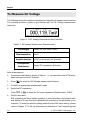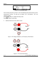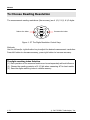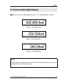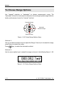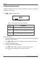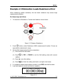
1
User’s Guide RIGOL Publication number: UGC01106-1110 DM3000 Series Digital Multimeter DM3061/2/4 DM3051/2/4 © 2007 RIGOL Technologies, Inc. All Rights Reserved RIGOL z z z z © 2007 RIGOL Technologies, Inc. All Rights Reserved. RIGOL products are protected by patent law in and outside of P.R. China. Information in this publication replaces all previously corresponding material. RIGOL Technologies, Inc. reserves the right to modify or change part of or all the specifications and pricing policies at company’s sole decision. NOTE: RIGOL is registered trademark of RIGOL TECHNOLOGIES, INC. © 2007 RIGOL Technologies, Inc. User’s Guide for DM3000 Series I RIGOL Safety Notices Review the following safety precautions carefully before operating the instrument to avoid any personal injuries or damages to the instrument and any products connected to it. To avoid potential hazards use the instrument as specified by this user’s guide only. The instrument should be serviced by qualified personnel only. To Avoid Fire or Personal Injury. Use Proper Power Cord. Use the power cord designed for the instrument as authorized in your country only. Ground The Instrument. The instrument is grounded through the grounding conductor of the power cord. To avoid electric shock the instrument grounding conductor(s) must be grounded properly before making connections to the input or output terminals of the instrument. Observe All Terminal Ratings. To avoid fire or shock hazard, observe all ratings and marks on the instrument. Follow the user’s guide for further ratings information before making connections to the instrument. Do Not Operate Without Covers. Do not operate the instrument with covers or panels removed. Use Proper Fuse. Use the fuse of the type, voltage and current ratings as specified for the instrument. Avoid Circuit or Wire Exposure. Do not touch exposed connections and components when power is on. Do Not Operate With Suspected Failures. If suspected damage occurs with the instrument, have it inspected by qualified service personnel before further operations. Do Not Operate in Wet/Damp Conditions. Do Not Operate in an Explosive atmosphere. Keep Product Surfaces Clean and Dry. II © 2007 RIGOL Technologies, Inc. User’s Guide for DM3000 Series RIGOL The disturbance test of all the models meet the limit values of A in the standard of EN 61326: 1997+A1+A2+A3, but can’t meet the limit values of B. WARNING IEC Measurement Category II. The HI and LO input terminals may be connected to mains in IEC Category II installations for line voltages up to 300 VAC. To avoid the danger of electric shock, do not connect the inputs to mains for line voltages above 300 VAC. Protection Limits: To avoid instrument damage and the risk of electric shock, do not exceed any of the Protection Limits defined in the following section. IEC Measurement Category II Overvoltage Protection To protect against the danger of electric shock, the RIGOL DM3000 series Digital Multimeter provides overvoltage protection for line-voltage mains connections meeting both of the following conditions: The HI and LO input terminals are connected to the mains under Measurement Category II conditions, defined below, and The mains are limited to a maximum line voltage of 300 VAC. IEC Measurement Category II includes electrical devices connected to mains at an outlet on a branch circuit. Such devices include most small appliances, test equipment, and other devices that plug into a branch outlet or socket. The DM3000 series Digital Multimeter may be used to make measurements with the HI and LO inputs connected to mains in such devices, or to the branch outlet itself (up to 300 VAC). However, the DM3000 series Digital Multimeter may not be used with its HI and LO inputs connected to mains in permanently installed electrical devices such as the main circuit-breaker panel, sub-panel disconnect boxes, or permanently wired motors. Such devices and circuits are subject to overvoltage that may exceed the protection limits of the DM3000 series Digital Multimeter. Note: Voltages above 300 VAC may be measured only in circuits that are isolated from mains. However, transient overvoltage are also present on circuits that are isolated from mains. The DM3000 series Digital Multimeter is designed to safely withstand occasional transient overvoltage up to 2500 Vpk. Do not use this equipment to measure circuits where transient overvoltage could exceed this level. © 2007 RIGOL Technologies, Inc. User’s Guide for DM3000 Series III RIGOL Safety Terms and Symbols Terms in This Guide. These terms may appear in this guide: ! WARNING: Warning statements identify conditions or practices that could result in injury or loss of life. ! CAUTION: Caution statements identify conditions or practices that could result in damage to this product or other property. ! CAT II (300V): IEC Measurement Category II. Inputs may be connected to mains (up to 300 VAC) under Category II overvoltage conditions. Terms on the Product: These terms may appear on the product: DANGER indicates an injury hazard may happen immediately. WARNING indicates an injury hazard may not happen immediately. CAUTION indicates that a potential damage to the instrument or other property might occur. Symbols on the Product: These symbols may appear on the Instrument: ! Hazardous Voltage IV Refer to Instructions Protective Earth Terminal Chassis Ground Earth Ground © 2007 RIGOL Technologies, Inc. User’s Guide for DM3000 Series RIGOL General-Purpose Multimeter The book covers the following description and six models DM3000 Series Digital Multimeter: DM3061, DM3062, DM3064; DM3051, DM3052, DM3054. DM3000 Series Digital Multimeter naming rules: DM 30 6 1 Prefix desktop Digital Multimeter Serial Number 6-6½, 5-5¾ digit No. 1-Basic; 2-LAN/GPIB interface; 4-Inspection plate with the model and LAN/GPIB interface. Application examples: DM3061- 6½ DM3000 series, Basic type. DM3062- 6½ DM3000 series, Basic type, equipped with LAN/GPIB module. DM3064 - 6½ DM3000 series, Basic type, equipped with LAN/GPIB and inspection module. DM3051- 5¾ DM3000 series, Basic type. DM3052- 5¾ DM3000 series, Basic type, equipped with LAN/GPIB module. DM3054 - 5¾DM3000 series, Basic type, equipped with LAN/GPIB and inspection module. © 2007 RIGOL Technologies, Inc. User’s Guide for DM3000 Series V RIGOL RIGOL DM3000-Series Digital Multimeter is a equipment designed for high-precision, multifunction, automation measurements. The series includes 6½ digits multimeter, with high-speed data acquisition, automatic measurements, multiplexer, mathematical operations, and flexible user sensor configurations etc. Interface includes RS-232, USB, LAN, GPIB for disk storage and print. The DM3000 has a high-resolution monochrome LCD display system for simple waveform display and recording. The concise and user-friendly layout of the front panel has a keyboard, and back lighted functional buttons, embedded with operating instructions makes the instrument more flexible, and capable. The 50kSa/s high data sampling rate allows to capture precision audio waveforms and high speed data. It has 2Mbyte of internal memory depth while the external memory depth is expandable as preferred. The AC voltage and current measurement is true RMS. It supports virtual terminal display and control, and remote network access. With the performance and characteristics given below, you will understand how a DM3000 can satisfy your measurement requirements. z z z z z z z VI 50kSa/s data sampling rate can be used, such as the rapidly changing high-precision audio waveform data. Meanwhile waveform can be displayed on LCD Screen Resolving Index: > 6½ digits and 2,400,000 Count 24 measurement functions DC voltage and current, AC voltage and current, two-wire and four-wire resistance, capacitance, continuity test, diode test, frequency, cycle, ratio measurements, sensor measurement, and so on. Upper limit and lower limit on threshold measurement Arithmetic include: maximum, minimum, limit, average, dBm, dB Data acquisition functions include : data records, inspection, automatic measurement. True RMS AC voltage and current measurement 16-Channels inspection functional measurement and control software (optional) DC voltage >10GΩ input impedance to achieve the range of 48V (±24V) 10 groups measuring set-up storage and unlimited setup through PC interface © 2007 RIGOL Technologies, Inc. User’s Guide for DM3000 Series RIGOL z z z z 256 x 64 pixel monochrome LCD I/O: RS-232, USB, LAN and GPIB Built-in USB Host to support USB disk and USB printer Simple, convenient, flexible control software: Ultralogger, Ultrasensor and UltraDMM Supports for Microsoft® Windows 98/Me/2000/XP Note: The chapter one, chapter two, chapter three will be described according to 6½ digits. For 5¾ digits, please refer to ‘’Chapter five: Characteristics for DM306x’’. © 2007 RIGOL Technologies, Inc. User’s Guide for DM3000 Series VII RIGOL Content Safety Notices ...........................................................................................II General-Purpose Multimeter ....................................................................... V CHAPTER 1 QUICK START.....................................................................1-1 General Inspection.................................................................................. 1-2 Handle Adjustment ................................................................................. 1-3 The Front/Rear Panel and User Interface.................................................. 1-4 To Measure DC Voltage ........................................................................... 1-6 To Measure AC Voltage ........................................................................... 1-8 To Measure DC Current ......................................................................... 1-10 To Measure AC Current ......................................................................... 1-12 To Measure Resistance.......................................................................... 1-14 To Measure Capacitance........................................................................ 1-18 To Test Continuity ................................................................................ 1-20 To Check Diodes................................................................................... 1-22 To Measure Frequency and Period ......................................................... 1-24 To Measure Sensor ............................................................................... 1-28 To Choose Reading Resolution............................................................... 1-34 To Choose Data Digit Display................................................................. 1-35 To Choose Range Options ..................................................................... 1-36 To Control Trigger Options .................................................................... 1-38 CHAPTER 2 OPERATING YOUR MULTIMETER.......................................2-1 To Set up Measurement Parameters......................................................... 2-2 Math Functions ..................................................................................... 2-12 To Set Up Triggering Parameter Function ............................................... 2-19 Store and Recall ................................................................................... 2-27 To Set Up the Utility.............................................................................. 2-32 High-Speed Data Log ............................................................................ 2-48 Multi-Route Scanning ............................................................................ 2-56 How to Use the Built-in Help System ...................................................... 2-64 CHAPTER 3 APPLICATION EXAMPLES ..................................................3-3 Example Example Example Example VIII 1: 2: 3: 4: Reading Statistic Functions..................................................... 3-3 Elimination Leads Resistance Error.......................................... 3-5 dBm Measurement ................................................................ 3-6 dB Measurement ................................................................... 3-7 © 2007 RIGOL Technologies, Inc. User’s Guide for DM3000 Series RIGOL Example 5: Limit Test.............................................................................. 3-9 Example 6: Temperature Sensor ............................................................ 3-10 Example 7: Reading Hold ...................................................................... 3-15 CHAPTER 4 PROMPT MESSAGES& TROUBLESHOOTING ...................... 4-1 Prompting Message................................................................................. 4-1 Troubleshooting...................................................................................... 4-3 CHAPTER 5 CHARACTERISTICS ........................................................... 5-1 Characteristics for DM306x ...................................................................... 5-1 Characteristics for DM305x .................................................................... 5-11 CHAPTER 6 APPENDIX ......................................................................... 6-1 Appendix Appendix Appendix Appendix A: DM3000 Series Accessories ................................................... 6-1 B: Warranty (DM3000 Series Digital Multimeters)........................ 6-2 C: General Care and Cleaning.................................................... 6-3 D: Contact RIGOL..................................................................... 6-4 © 2007 RIGOL Technologies, Inc. User’s Guide for DM3000 Series IX RIGOL Chapter 1 Quick Start This chapter covers the following topics: General Inspection Handle Adjustment The Front Panel and User Interface To Measure DC Voltage To Measure AC Voltage To Measure DC Current To Measure AC Current To Measure Resistance To Measure Capacitance To Test Continuity To Check Diodes To Measure Frequency and Period To Make an Sensor measurement To Choose Digits resolving index To Choose Data Digit Display To Choose Range Options To Control Trigger Options © 2007 RIGOL Technologies, Inc. User’s Guide for DM3000 Series 1-1 RIGOL General Inspection Inspect a new DM3000 Digital Multimeter with the following steps: 1. Inspect the shipping container for damage. Keep the damaged shipping container or cushioning material until the contents of the shipment have been checked for completeness and the instrument has been checked mechanically and electrically. 2. Check the accessories. Accessories supplied with the instrument are listed in "Accessories" at Appendix B of this guide. If the contents are incomplete or damaged, please notify the RIGOL Sales Representative. 3. Inspect the instrument. In case of any damage, or defect, or failure, notify the RIGOL Sales Representative. If the shipping container is damaged, or the protective material shows signs of stress, notify the carrier as well as your RIGOL sales office. Keep the shipping materials for the carrier’s inspection. RIGOL offices will arrange reparation or replacement at RIGOL’s option without waiting for claim settlement. 1-2 © 2007 RIGOL Technologies, Inc. User’s Guide for DM3000 Series RIGOL Handle Adjustment To adjust the handle position of DM3000 Digital Multimeter, please grip the handle by the sides and pull it outward. Then, rotate the handle to the desired position as shown in Figure 1- 1, Figure 1- 2. Figure 1- 1 Figure 1- 2 Viewing Positions and Carrying Position © 2007 RIGOL Technologies, Inc. User’s Guide for DM3000 Series 1-3 RIGOL The Front/Rear Panel and User Interface It is important to get familiar with the front panel of a new DM3000. This chapter gives an introduction of the operation and functions of the Front Panel. The front panel of the DM3000 is user friendly as shown below. It includes 4 Direction buttons and 12 Function keys, 6 Menu keys and 2 Control keys as shows below: LCD Display On/Off USB Host Purple District: Measurement Function Keys Yellow District: Trigger Control Keys Direction Keys Menu Operation Blue Direction: Keys Function Selective Current Input Terminal Keys Figure 1- 3 The Front Panel 1-4 © 2007 RIGOL Technologies, Inc. User’s Guide for DM3000 Series RIGOL Current Input Fuse VMC GPIB (IEEE--488) 10/100 Ethernet Power Socket Differential USB Device RS--232 Power Fuse AC Voltage Multiplexer Interface Selector Ext Trigger Figure 1- 4 The Rear Panel Range Digits resolving index Local/Remote Operation Current Measurement Measurement Data Display Parameters Name Parameters Display Operation Menu Figure 1- 5 The Interface Explanation How the definitions express in this book: In this manual, the regarding keys writing expression has the same log with the keys on the front panel. It is noteworthy that the menu operates keys, marking with the belt shadow. For example, Conti indicates the short circuit option in menu © 2007 RIGOL Technologies, Inc. User’s Guide for DM3000 Series . 1-5 RIGOL To Measure DC Voltage The following shows the system connections and selection of measurement functions. This practice provides a guide to get familiar with the DC Voltage measurement technique. Figure 1- 6 DC Voltage Measurement Data Interface Table1- 1 DC Voltage Measurement Characteristics Five Ranges 200mV, 2V, 20V, 200V, 1000V Max Resolution 100nV Input Protection 1000V on all ranges (HI Terminal) Configurable Parameters Range, DC impedance, Null value Basic measurement: 1. Connect the test leads as shown in Figure 1- 7; red test lead to the HI Terminal, black test lead to the LO Terminal. to select the DC Voltage measurement function. 2. Press 3. 4. Choose the appropriate measurement range. Setup the DC impedance. Press 5. 1-6 Æ Res, to setup the DC input impedance (Default value: 10MΩ). Set the Null value. Null computing will be an option operation, it could be setup in accordance with user demand. If user does not implement Null computing, this parameter is not required. (To know the specific setting methods of the Null value setting, please refer to Chapter 2 “To Set Up Measurement Parameters”, Null computing)Lead © 2007 RIGOL Technologies, Inc. User’s Guide for DM3000 Series RIGOL test leads into circuit and start to measure. DC Voltage Figure 1- 7 DC Voltage Measurement 6. Use history function. Press History, the menu shows as below: Figure 1- 8 The History Data Use the history function to review or save the data that has acquired by the current measurement function. The data can be display “Info” (information), “List” and “HistoG” formats. Press Update softkey to update the History data. Press Save softkey to save data. Note Select Auto range if the measurement range is uncertain to get more accurate measurement data. © 2007 RIGOL Technologies, Inc. User’s Guide for DM3000 Series 1-7 RIGOL To Measure AC Voltage The following shows the system connections and selection of measurement functions. This practice provides a guide to get familiar with the AC Voltage measurement technique. (The AC functions only support 5½ digits measurement.) Figure 1- 9 AC Voltage Measurement Data Interface Table1- 2 AC Voltage Measurement Characteristics Five Ranges 200mV, 2V, 20V, 200V, 750V Max Resolution 100nV Input Protection 750VRMS on all ranges (HI Terminal) Configurable Parameters Range, DC impedance, Null value Steps: 1. Connect test leads as shown in Figure 1- 10; red test lead to the HI Terminal, black test lead to the LO Terminal. to select the AC Voltage measurement function. 2. Press 3. 4. Choose the appropriate measurement range. Setup the AC Filter. Press 5. 1-8 Æ Filter, to setup the AC Filter Bandwidth (Default value: Mid). Set the Null value. Null computing will be an option operation, could be setup in accordance with user demand. If user does not implement Null computing, this parameter is not required, direct implementation of the next step. © 2007 RIGOL Technologies, Inc. User’s Guide for DM3000 Series RIGOL (To know the specific setting methods of the Null value setting, please refer to Chapter 2 “To Set Up Measurement Parameters”, Null computing) 6. Lead test leads into circuit and start to measure. AC Voltage Figure 1- 10 AC Voltage Measurement 7. Use history function. Press History, the menu shows as below: Figure 1- 11 The History Data Use the history function to review or save the data that has acquired by the current measurement function. The data can be display “Info” (information), “List” and “HistoG” formats. Press Update softkey to update the History data. Press Save softkey to save data. © 2007 RIGOL Technologies, Inc. User’s Guide for DM3000 Series 1-9 RIGOL To Measure DC Current The following shows the system connections and selection of measurement functions. This practice provides a guide to get familiar with the DC Current measurement technique. Figure 1- 12 DC Current Measurement Data Interface Table1- 3 DC Current Measurement Characteristics Five Ranges 2mA, 20mA, 200mA, 1A, 10A Max Resolution 10nA Input Protection 10A, 250V Current Input Fuse on rear panel Configurable Parameters Range, Null value Steps: 1. Connect test leads as shown in Figure 1- 13; red test lead to the HI Terminal, black test lead to the LO terminal. 2. Press to select the DC Current measurement function. 3. Choose the appropriate measurement range. 4. Set the Null value. Null computing will be an option operation, could be setup in accordance with user demand. If user does not implement Null computing, this parameter is not required, direct implementation of the next step. (To know the specific setting methods of the Null value setting, please refer to Chapter 2 “To Set Up Measurement Parameters”, Null computing) 5. Lead test leads into circuit, start to measure. 1-10 © 2007 RIGOL Technologies, Inc. User’s Guide for DM3000 Series RIGOL DC Current Figure 1- 13 DC Current Measurement 6. Use history function. Press History, the menu shows as below: Figure 1- 14 The History Data Use the history function to review or save the data that has acquired by the current measurement function. The data can be display “Info” (information), “List” and “HistoG” formats. Press Update softkey to update the History data. Press Save softkey to save data. © 2007 RIGOL Technologies, Inc. User’s Guide for DM3000 Series 1-11 RIGOL To Measure AC Current The following shows the system connections and selection of measurement functions. The practice provides as guide to be familiar with the AC Current measurement technique. (The AC functions only support 5½ digits measurement.) Figure 1- 15 AC Current Measurement Data Interface Table1- 4 AC Current Measurement Characteristics Five Ranges 20mA, 200mA, 1A, 10A Max Resolution 100nA Input Protection 10A, 250V Current Input Fuse on rear panel Configurable Parameters Range, AC Filter, Null value Steps: 1. Connect test leads as shown in Figure 1- 16; red test lead to the HI Terminal, black test lead to LO Terminal. to select the AC Current measurement function. 2. Press 3. 4. Choose the appropriate measurement range. Setup the AC Filter. Press 5. 1-12 Æ Filter, to setup the AC Filter Bandwidth (Default value: “Mid” (Middle)). Set the Null setting value. Null computing will be an option operation, could be setup in accordance with user © 2007 RIGOL Technologies, Inc. User’s Guide for DM3000 Series RIGOL demand. If user does not implement Null computing, this parameter is not required, direct implementation of the next step. (To know the specific setting methods of the Null value setting, please refer to Chapter 2 “To Set Up Measurement Parameters”, Null computing) 6. Lead test leads into circuit and start to measure. AC Current Figure 1- 16 AC Current Measurement 7. Use history function. Press History, the menu shows as below: Figure 1- 17 The History Data Use the history function to review or save the data that has acquired by the current measurement function. The data can be display “Info” (information), “List” and “HistoG” formats. Press Update softkey to update the History data. Press Save softkey to save data. © 2007 RIGOL Technologies, Inc. User’s Guide for DM3000 Series 1-13 RIGOL To Measure Resistance The following shows the system connections and selection of measurement functions. The practice provides a guide get familiar with the Resistance measurement technique. Resistance measurement methods include 2-Wire Resistance Measurement and 4-Wire Resistance Measurement, and will explain separately. 2-Wire Resistance Measurement Figure 1- 18 2-Wire Resistance Measurement Interface Table1- 5 Resistance Measurement Characteristics Seven Ranges Max Resolution Open-circuit Voltage Input Protection Configurable Parameters 200Ω, 2kΩ, 20kΩ, 200kΩ, 1MΩ, 10MΩ, 100MΩ 100uΩ <7V 1000V on all ranges (HI Terminal) Range, Null value Steps: 1. Connect test leads as shown in Figure 1- 19; red test lead to the HI Terminal, black test lead to the LO Terminal. to select the 2-Wire Resistance Measurement. 2. Press 3. 4. Choose the appropriate measurement range. Set the Null value 1-14 © 2007 RIGOL Technologies, Inc. User’s Guide for DM3000 Series RIGOL Null computing will be an option operation, could be setup in accordance with user demand. If user does not implement Null computing, this parameter is not required, direct implementation of the next step. (To know the specific setting methods of the Null value setting, please refer to Chapter 2 “To Set Up Measurement Parameters”, Null computing) 5. Lead test leads into circuit and start to measure. Resistance Figure 1- 19 2-Wire Resistance Measurement 6. Use history function. Press History, the menu shows as below: Figure 1- 20 The History Data Use the history function to review or save the data that has acquired by the current measurement function. The data can be display “Info” (information), “List” and “HistoG” formats. Press Update softkey to update the History data. Press Save softkey to save data. NOTE When measuring small value resistance, Null operation will be recommended, the test wire impedance error could be eliminated. © 2007 RIGOL Technologies, Inc. User’s Guide for DM3000 Series 1-15 RIGOL 4-Wire Resistance Measurement Figure 1- 21 Table1- 6 Resistance Measurement Characteristics Seven Ranges Max Resolution Open-circuit Voltage 200Ω, 2kΩ, 20kΩ, 200kΩ, 1MΩ, 10MΩ, 100MΩ 100uΩ <7V (1). 200VPK Import Protection (2). 1000V on all ranges (HI Terminal) (3). 200V on all ranges (HI Sense, LO Sense) Configurable Parameters Range, Null value Steps: 1. Connect test leads as show in Figure 1- 22; red test lead to the HI Terminal, black test lead to the LO Terminal. 2. Press twice to select the 4-Wire Resistance Measurement. 3. 4. Choose the appropriate measurement range. Set the Null setting value. Null computing will be an optional operation, it could be setup in accordance with users’ demand. If user does not implement Null computing, this parameter is not required, direct implementation of the next step. (To know the specific setting methods of the Null value setting, please refer to Chapter 2 “To Set Up Measurement Parameters”, Null computing) 5. Lead test leads into circuit, start to measure. 1-16 © 2007 RIGOL Technologies, Inc. User’s Guide for DM3000 Series RIGOL 4-Wire Sense HI Resistance 4-Wire Sense LO Figure 1- 22 4-Wire Resistance Measurement 6. Use history function. Press History, the menu shows as below: Figure 1- 23 The History Data Use the history function to review or save the data that has acquired by the current measurement function. The data can be display “Info” (information), “List” and “HistoG” formats. Press Update softkey to update the History data. Press Save softkey to save data. NOTE When measuring resistances, avoid contacting both ends of the resistor for accurate measurement. © 2007 RIGOL Technologies, Inc. User’s Guide for DM3000 Series 1-17 RIGOL To Measure Capacitance The following shows the system connections and selection of measurement functions. The practice provides a guide to get familiar with the Capacitance measurement technique. Figure 1- 24 Capacitance Measurement Data Interface Table1- 7 Capacitance Measurement Characteristics Six Ranges 2nF, 20nF, 200nF, 2uF, 20uF, 200uF Max Resolution 0.1pF Input Protection 1000V on all ranges (HI Terminal) Configurable Parameters Range, Null value Basic measurement: 1. Connect test leads as shown in Figure 1- 25; red test lead to the HI Terminal, black test lead to the LO Terminal. 2. Press to select the Capacitance measurement function. 3. 4. Choose the appropriate measurement range. Set the Null value. Null computing will be an optional operation, could be setup in accordance with userdemand. If user does not implement Null computing, this parameter is not required, direct implementation of the next step. (To know the specific setting methods of the Null value setting, please refer to Chapter 2 “To Set Up Measurement Parameters”, Null computing) 5. Lead test leads into circuit, start to measure. 1-18 © 2007 RIGOL Technologies, Inc. User’s Guide for DM3000 Series RIGOL Capacitance Figure 1- 25 Capacitance Measurement 6. Use history function. Press History, the menu shows as below: Figure 1- 26 The History Data Use the history function to review or save the data that has acquired by the current measurement function. The data can be display “Info” (information), “List” and “HistoG” formats. Press Update softkey to update the History data. Press Save softkey to save data. NOTE Before measuring the electrolytic capacitance, you should make the two legs of the electrolytic capacitance short circuit and let it be discharged, and then you can measure it. © 2007 RIGOL Technologies, Inc. User’s Guide for DM3000 Series 1-19 RIGOL To Test Continuity The following shows the system connections and the selection of measurement functions. The practice provides a guide to get familiar with the Continuity measurement technique. Figure 1- 27 Continuity Measurement Data Interface Table1- 8 Continuity Measurement Characteristics Tests Current Max Resolution Open-circuit Voltage Input Protection Configurable Parameters 1mA Range fixed at 2KΩ <7V 1000V (HI Terminal) 0≤Rtesting≤Short-circuit impedance (0Ω≤Short-circuit impedance≤2kΩ) Steps: 1. Connect test leads as Figure 1- 28 shown. Red test lead connects the HI Terminal, Black test lead connects the LO Terminal. to select the Continuity Measurement. 2. Press 3. Setup the Short-circuit resistance. Press Set button to set up the Short-circuit Impedance. The default value is 10Ω. User may carry on the Continuity measurement directly without modification. Lead test leads into circuit, start to measure. 4. 1-20 © 2007 RIGOL Technologies, Inc. User’s Guide for DM3000 Series RIGOL I Open or Closed Circuit Figure 1- 28 Continuity Measurement © 2007 RIGOL Technologies, Inc. User’s Guide for DM3000 Series 1-21 RIGOL To Check Diodes The following shows the system connections and selection of measurement functions. The practice provides a guide to get familiar with the Check Diodes technique. Figure 1- 29 Check Diodes Interface Table1- 9 Check Diodes Characteristics Tests Current 1mA Max Resolution Range fixed at 2VDC Open-circuit Voltage Input Protection Configurable Parameters <7V 1000V (HI Terminal) 0.1V≤Vmeasured≤2V Steps: 1. Connect test leads as shown in Figure 1- 30, red test lead to the HI Terminal, black test lead to the LO Terminal. 2. 1-22 Press to select the Check Diodes. © 2007 RIGOL Technologies, Inc. User’s Guide for DM3000 Series RIGOL 3. Lead test leads into circuit and start to check. I Forward Bias Figure 1- 30 Check Diodes © 2007 RIGOL Technologies, Inc. User’s Guide for DM3000 Series 1-23 RIGOL To Measure Frequency and Period The following shows the system connections and selection of measurement functions. The practice provides a guide to get familiar with the Frequency and Period Measurement technique. Frequency Test Figure 1- 31 Frequency Measurement Data Interface Table1- 10 Frequency Test Characteristics Ranges 200mV, 2V, 20V, 200V, 750V Measurement Range Input Signal Range Input Protection Configurable Parameters 3Hz~300kHz 100mVAC ~ 750VAC 750VRMS on all ranges (HI Terminal) Null value Basic measurement: 1. Connect test leads as Figure 1- 32 shown. Red test lead connects the HI Terminal, Black test lead connects the LO Terminal. 2. Press to select the Frequency Test. 3. Set the Null value. Null computing will be an option operation, could be setup in accordance with user demand. If user does not implement Null computing, this parameter is not required, direct implementation of the next step. (To know the specific setting methods of the Null value setting, please refer to Chapter 2 “To Set Up Measurement Parameters”, Null computing) 1-24 © 2007 RIGOL Technologies, Inc. User’s Guide for DM3000 Series RIGOL 4. Lead test leads into circuit and start to check. AC Signal Figure 1- 32 Frequency Test 5. Use history function.. Press History, the menu shows as below: Figure 1- 33 The History Data Use the history function to review or save the data that has acquired by the current measurement function. The data can be display “Info” (information), “List” and “HistoG” formats. Press Update softkey to update the History data. Press Save softkey to save data. © 2007 RIGOL Technologies, Inc. User’s Guide for DM3000 Series 1-25 RIGOL Period Test Figure 1- 34 Period Measurement Data Interface Table1- 11 Period Test Characteristics Range 200mV, 2V, 20V, 200V, 750V Measurement Range Input Signal Range Import Protection Configurable Parameters 0.33s ~ 3.3us 100mVAC~750VAC 750VRMS on all ranges (HI Terminal) Null value Steps: 1. Connect test leads as Figure 1- 35 shown. Red test lead connects the HI Terminal, Black test lead connects the LO Terminal. 2. Press twice to select the Period Test. 3. Set the Null value. Null computing will be an optional operation, could be setup in accordance with users’ demand. If user does not implement Null computing, this parameter is not required, direct implementation of the next step. (To know the specific setting methods of the Null value setting, please refer to Chapter 2 “To Set Up Measurement Parameters”, Null computing) 1-26 © 2007 RIGOL Technologies, Inc. User’s Guide for DM3000 Series RIGOL 4. Lead test leads into circuit, start to check. AC Signal Figure 1- 35 Period Test 5. Use history function. Press History, the menu shows as below: Figure 1- 36 The History Data Use the history function to review or save the data that has acquired by the current measurement function. The data can be display “Info” (information), “List” and “HistoG” formats. Press Update softkey to update the History data. Press Save softkey to save data. © 2007 RIGOL Technologies, Inc. User’s Guide for DM3000 Series 1-27 RIGOL To Measure Sensor The DM3000 converts the sensor physical properties into electrical voltage, resistance, current for measurement. So it needs the sensor name, sensor type, sensor physical unit, sensor reference data, and arithmetic. Figure 1- 37 Table1- 12 Sensor Building Options New Newly built sensor reference data file Edit Edit a sensor reference data file Load Load a sensor reference data file Display Set display mode Steps: 1. Connect test leads as shown in Figure 1- 54, Figure 1- 55, red test leads to the HI Terminal, black test leads to the LO Terminal. to select the Sensor function. 2. Press 3. Press New, the display shows: Figure 1- 38 (1). In New function interface, press Prpty to edit the sensor Name, sensor Type and physical characteristics of the sensor. 1-28 © 2007 RIGOL Technologies, Inc. User’s Guide for DM3000 Series RIGOL Figure 1- 39 Press Name button, create a name for the sensor reference name. Figure 1- 40 Press Done button to finish the input work. Press Type button, to select the sensor type, include: DC voltage,DC current,2-wire, 4-wire resistance and frequency. Press Figure 1- 41 button back to the higher level menu. Press Unit button, to select the physical unit, include: ℃, Pa, %, °, and F. Press Figure 1- 42 button back to the higher level menu. In New interface, press Define button to build the reference table. Figure 1- 43 © 2007 RIGOL Technologies, Inc. User’s Guide for DM3000 Series 1-29 RIGOL Press Add button, to input the Measured and Corresponding value to the reference value data. Figure 1- 44 Figure 1- 45 Figure 1- 46 Press SEG button, you are allowed to segment the reference value with different arithmetic. Press Arith button select the algorithms to Linear or Curvilinear. Figure 1- 47 Figure 1- 48 1-30 © 2007 RIGOL Technologies, Inc. User’s Guide for DM3000 Series RIGOL Press return to New interface then press Done button, you have finished the input work, then you can use this sensor reference immediately, or you can save it into the built-in storage space or your U-disk for future work. Figure 1- 49 Press Apply button, to use this reference value file. Press Save to save the file. Figure 1- 50 Press Save button, to finish the save operation. Figure 1- 51 Press Apply button, to start the sensor measurement. Figure 1- 52 (2). (3). (4). (5). Press Press Press Press Edit button, to edit the saved sensor reference values. Load button, to load the saved sensor reference file. Disp button, to choose the value to be shown on the display interface. History, enter the menu shown below: © 2007 RIGOL Technologies, Inc. User’s Guide for DM3000 Series 1-31 RIGOL Figure 1- 53 The History Data Use the history function to review or save the data that has acquired by the current measurement function. The data can be display “Info” (information), “List” and “HistoG” formats. Press Update softkey to update the History data. Press Save softkey to save data. 4. Lead test leads into circuit, start to check. Sensor Figure 1- 54 Voltage, Resistance, and Frequency Mode Sensor Sensor Figure 1- 55 Current Mode Sensor 1-32 © 2007 RIGOL Technologies, Inc. User’s Guide for DM3000 Series RIGOL Figure 1- 56 Choosing interfaces of Measure and Correspond Value © 2007 RIGOL Technologies, Inc. User’s Guide for DM3000 Series 1-33 RIGOL To Choose Reading Resolution The measurement reading resolutions (the accuracy) are 4 1/2, 5 1/2, 6 1/2 digits. Reduce the index Increases the index Figure 1- 57 The Digits Resolution Control Keys Methods: Use the left and/or right direction key to adjust the desired measurement resolution. Press left button to decrease accuracy, press right button to increase accuracy. The digits resolving index Selection (1). Each precision of the measure function can be set separately without influence. (2). Choose the reading precision of 6 1/2 bit when measuring AC for best results. (3). Save the digits resolving index in volatile memory. 1-34 © 2007 RIGOL Technologies, Inc. User’s Guide for DM3000 Series RIGOL To Choose Data Digit Display Function to set up data display format; 5, 6 or 7 digits (Default: 5 digits). Figure 1- 58 7 Digits Data Figure 1- 59 6 Digits Data Figure 1- 60 5 Digits Data NOTE In high-accuracy measurement, if users need to show less data digit, it can show fewer digits for user-friendly reading. © 2007 RIGOL Technologies, Inc. User’s Guide for DM3000 Series 1-35 RIGOL To Choose Range Options Use “manual” selection or “automatic” to choose measurement range. The “automatic” allows the instrument to determine the most appropriate range while for better performance choose the “manual” method. Increased range Automatic selection range Reduced range Figure 1- 61 Choice Range Options Keys Methods 1: Use up and down direction keys to adjust the Range. Press Up to increase the range, press Down to reduce the range. Press key, to select the automatic method. Methods 2: Use the menu option keys to adjust the range as shown in the following Figure 1- 62. Figure 1- 62 Choice Range Options Menu 1-36 © 2007 RIGOL Technologies, Inc. User’s Guide for DM3000 Series RIGOL Table1- 13 Choice Range Option Menu Option Menu Explain Auto Start automatically adjustment range, and banned manually adjustment range. Range+ Start manually increased range, and banned automatically adjustment range. Range- Start manually reduced range, and banned automatically adjustment range. Operation description: z When the input signal is beyond the current scope of the measurement range, the multimeter will show “OVER RANGE”. z After restarting and remote- replacement, range options will turn back default option “Automatic choice range”. z When testing the Continuity and Checking the diodes, the range option are fixed. The range of Continuity is 2KΩ while the diodes are 2VDC. NOTE Other functions of the direction keys: At measurement parameters setting menu, press the up and down keys to choose setting areas. At data input interface, press up and down keys to change the number. Press left and right keys to change the different digits. © 2007 RIGOL Technologies, Inc. User’s Guide for DM3000 Series 1-37 RIGOL To Control Trigger Options Use or to trigger the multimeter. When the multimeter is powered up, the key will be on, indicating means this function is running. Figure 1- 63 Trigger Control Keys Multimeter triggering options include Automatically, Single and Hold. Auto Triggering key once, it takes continuous readings at the fast rate the specified Press measurement configuration. Single Triggering key the multimeter takes one reading, or a number of readings specified Press by a sample count entered. Holding Triggering Press display. NOTE Press 1-38 key, it allows capturing and holding a stable reading on the front panel button, during Remote Mode, to switch back to the local mode. © 2007 RIGOL Technologies, Inc. User’s Guide for DM3000 Series RIGOL Chapter 2 Operating Your Multimeter By now the front/rear panel, the function control area and keys, and the ways to set up the multimeter have been introduced. This chapter goes through all groups of front-panel buttons and menus, and extends the knowledge the operation instructions. Follow the exercises to get the most of the powerful measurement capabilities of the multimeter. This chapter covers the following topics: To Set up Measurement Parameters ( ) To Make Mathematics Operation ( ) To Set up Trigger System ( ) To Save and Recall ( ) To Set up Utility ( ) To Set up High-speed data acquisition ( ) ( ) and Multi-route Scanning Use the built-in help system © 2007 RIGOL Technologies, Inc. User’s Guide for DM3000 Series 2-1 RIGOL To Set up Measurement Parameters Press key to enter the Measurement Menu for setting to set up the measurement parameters. Users may use the factory defaults or establish desired configurations. The Measurement parameters Menu includes: Conti, Filter, Res, Null, and Ratio. To change these parameters, satisfy the dissimilar condition of the measurement request. Table 2- 1 Menu Description Function Menu Description Conti Set up the resistance value in continuity test. Filter Choose the AC filter bandwidth. Res Choose the DC voltage input impedance. Null Set up null value. Ratio Measured the ratio of two DC voltage signal. Freq Measured the frequency of AC signal. Save all changes, and end the current operation. 2-2 © 2007 RIGOL Technologies, Inc. User’s Guide for DM3000 Series RIGOL Continue Resistance Set up the continue resistance value in the short test menu. When the measured resistance is below limit, the DM3000 will beep to indicate the circuit continuation. The continue resistance is only using at Continue Test. Press Æ Conti, enter the menu shown below: Figure 2- 1 Use direction keys to change the parameter values: Press left and right directional keys to choose different digits. Press up and down keys to change the current digit value. Continue Resistance The range of continue resistance is 1Ω~2000Ω. The default value is 10Ω. The continue resistance value stored in the nonvolatile memory, the resistance still keep when the power is off. © 2007 RIGOL Technologies, Inc. User’s Guide for DM3000 Series 2-3 RIGOL AC Filter There are three settings at the AC Filter menu. Choose the appropriate setting for more accurate measurements. This function applies AC Voltage and AC Current measurement only. Press Æ Filter, enter the menu shown below: Figure 2- 2 Table 2- 2 AC Filter Menu Description Function Description Menu Slow Set up the filter with low speed. Mid Set up the filter with to middle speed. Fast Set up the filter with high speed. Save all changes, back to a higher level menu. Table 2- 3 AC Filter Parameters Characteristics AC Filter Options Input Frequency Setting Timer Slow 3Hz~300kHz 1.2 reading/s Mid 20Hz~300kHz 0.5 reading/s Fast 200Hz~300kHz 0.3 reading/s AC Filter The AC Filter Parameters are saved in the volatile memory, the data will lose when the power is off. The default value of AC Filter Parameters is “Mid” (middle). 2-4 © 2007 RIGOL Technologies, Inc. User’s Guide for DM3000 Series RIGOL DC Input Impedance The options of input resistance for DC value measurements are 10MΩ and >10GΩ. For 200mV, 2V, 20V measuring ranges, choose >10MΩ for better result. Press Æ Res, enter the menu shown below: Figure 2- 3 Table 2- 4 DC Input Resistance Menu Description Function Menu 10MΩ >10GΩ Description Set up the DC Input Impedance to 10MΩ. Set up the DC Input Impedance to >10GΩ. Save all changes, back to a higher level menu. DC input resistance selection: (1). While the DC input resistance is selected to 10MΩ, the input resistance of all measurement range is 10MΩ; (2). While the DC input resistance is selected to >10GΩ, the input resistance for 200mV, 2V and 20V measurement range is >10GΩ; for 200V and 1000V measurement range is kept at 10MΩ. © 2007 RIGOL Technologies, Inc. User’s Guide for DM3000 Series 2-5 RIGOL Null Measurement The DM3000 null settings is available for DC voltage, AC voltage, DC current, AC current, resistance, frequency/period, and capacitance measurements. With null setting each measurement is the difference between a stored null value and input signal. The null measurement enhance the accuracy by off set test lead impedance. It is particularly important prior for making capacitance measurements. The formula used for calculating null measurements is: Result = reading - null value The null value is adjustable, and can be set to any value between 0 and ±120% of the highest range, for the present function. Press Æ Null, the display shows: Figure 2- 4 Table 2- 5 Null Measurement Menu Description Function Menu Current Clear On/Off Description Use the measured value as the null value. Set the value to be zero. Turn the Null function on or off. Save all changes, back to a higher level menu. 2-6 © 2007 RIGOL Technologies, Inc. User’s Guide for DM3000 Series RIGOL Null measurement parameters setting methods: (1). In operation interface press Null button, use the current value to be Null value. (2). To select null function. Start null function, the multimeter will use the current value to Null value. (3). In Null setting display interface, it uses the Direction Keys to input null value. © 2007 RIGOL Technologies, Inc. User’s Guide for DM3000 Series 2-7 RIGOL Ratio Measurement Use Ratio measurement to measure the ratio of 2 DC voltage signal. Ratio measurement is only for measuring DC voltage. Press Æ Ratio, the display shows: Figure 2- 5 Table 2- 6 Ratio Measurement Menu Description Function Menu Description ON Enable the Ratio Measurement Function. OFF Disable the Ratio Measurement Function. Save all changes, back to a higher level menu. The method of the radio measurement: Ratio= DC⋅ Voltage Voltage DC DC Re frenceVaoltage DC Reference Voltage (1). Measuring Sense Terminal, for measuring reference DC voltage. Default automatic range option under 10V. (2). Measuring Input Terminal, for measuring DC voltage. The measuring voltage scope is under 10V. (3). Input LO Terminal and Sense LO Terminal must have a common reference value, and the voltage difference cannot surpass ±1V. 2-8 © 2007 RIGOL Technologies, Inc. User’s Guide for DM3000 Series RIGOL Basic measurement: 1. Connect test leads shown in Figure 2- 6; red test leads to the HI Terminal, black test leads to the LO Terminal. to select the DC Voltage measurement function. 2. Press 3. 4. Choose the appropriate measurement range. Set up the DC Ratio Measurement. Press 5. Æ Ratio Æ On, to start the DC Ratio Measurement. Lead test leads into circuit, start to measure. Signal Voltage Reference Voltage Figure 2- 6 Ratio Measurement © 2007 RIGOL Technologies, Inc. User’s Guide for DM3000 Series 2-9 RIGOL Frequency Measurement Frequency measurement function is used for measuring the frequency of AC signal (voltage and current) only. Press Æ Freq, the display shows: Figure 2- 7 Table 2- 7 Ratio Measurement Menu Description Function Menu Description ON Activate the Frequency Measurement Function OFF Deactivate the Frequency Measurement Function Save all changes, back to a higher level menu. Basic measurement: 1. Connect test leads as shown in Figure 2-9; red test lead to the HI Terminal, black test lead to the LO Terminal. or to select the AC voltage or current measurement function. 2. Press 3. 4. Choose the appropriate range. Set up the AC Frequency Measurement. Press Press 2-10 Æ Freq Æ On, to start the AC Frequency Measurement. to save all changes, back to a higher level menu. © 2007 RIGOL Technologies, Inc. User’s Guide for DM3000 Series RIGOL 5. Lead test leads into circuit, start to measure. AC Voltage Figure 2- 8 AC Current Figure 2- 9 Figure 2- 10 Frequency Measurement Display Interface © 2007 RIGOL Technologies, Inc. User’s Guide for DM3000 Series 2-11 RIGOL Math Functions Press key, the display shows: Figure 2- 11 The DM3000 provides five math functions: Null, statistic, dB, dBm and Limit testing. Only one of these math functions can be enabled at a time, and remains in effect until change. In Math function interface, choose the required math function. Press On to start the Math function. Math functions are the combination of mathematical and the basic measurement operation. However, not all combinations are supported. In such case the math function will automatically turn off. Table 2- 8 Math Function Menu Description Function Menu Settings Reading statistic functions, including: Max, Min, Average, and number of measurement. Statistic The dB measurement is the difference between the input signal and a stored relative value. The dBm function is logarithmic, and is based on a calculation of power delivered to reference impedance. The limit test function performs pass/fail testing with upper and lower limits that you specify. dB dBm Limit ON/OFF Description ON OFF Turn on Math function. Turn off Math function. Save all changes, back to a higher level menu. 2-12 © 2007 RIGOL Technologies, Inc. User’s Guide for DM3000 Series RIGOL Table 2- 9 shows the supported combination. Table 2- 9 Math Function is used for the following measurement applications Measurement Function Statistic dB dBm Limit DC Voltage Support Support Support Support AC Voltage Support Support Support Support DC Current Support Support AC Current Support Support 2-Wire Resistance Support Support 4-Wire Resistance Support Support Frequency Support Support Period Support Support Ratio Support Support Capacitance Support Support Supported the Math function Continuity Diodes © 2007 RIGOL Technologies, Inc. User’s Guide for DM3000 Series 2-13 RIGOL Math Functions Selective The DM3000 provides five math functions: Null measurements, Total measurements, dB measurements, dBm measurements, and Limit testing. Only one of these math functions can be enabled at the same time, and remains in effect until you turn it off or change it. Press key, the display shows: Figure 2- 12 Table 2- 10 Math Functions Menu Function Description Function Menu Settings Reading statistic functions, including: Max, Min, Average, and number of measurement. Statistic The dB measurement is the difference between the input signal and a stored relative value. The dBm function is logarithmic, and is based on a calculation of power delivered to reference impedance. The limit test function performs pass/fail testing with upper and lower limits that you specify. dB dBm Limit ON/OFF Description ON OFF Turn on Math function. Turn off Math function. Save all changes, back to a higher level menu. 2-14 © 2007 RIGOL Technologies, Inc. User’s Guide for DM3000 Series RIGOL 1. Statistic Measurement The Statistic function is for DC voltage, AC voltage, DC current, AC current, resistance, frequency/period, and capacitance measurement. The front panel can display the statistical data for any set of readings: average (Ave), maximum (Max), minimum (Min), and which can read with All function and the number of samples taken (Total). Figure 2- 13 Press Æ Stats, the display shows: Figure 2- 14 Table 2- 11 Statistic Measurement Menu Function Description Function Menu Description Max (Maximum) Maximum value from a set of measurements. Min (Minimum) Statistical measurement all reading Min value. Ave (Average) Statistical measurement all reading Average value. All The complete a set of measurement. Save all changes, back to a higher level menu. © 2007 RIGOL Technologies, Inc. User’s Guide for DM3000 Series 2-15 RIGOL 2. Limit Measurement Use the Limit test function to perform pass/fail testing with respect to specified upper and lower limits. The limits can be set to any value between 0 and ±120% of the highest range of the current function. The upper limit must be positive than the lower limit. Press Æ Limit, the display shows: Figure 2- 15 Table 2- 12 Limit Measurement Menu Function Description Function Menu Settings Description High Set the desired Upper limit. Low Set the desired Lower limit. Save all changes, back to a higher level menu. The range of Limit function: (1). The limit value scope is 0%~±120% of the current measurement range. (2). The upper limit value should be always bigger than the lower limit value. 2-16 © 2007 RIGOL Technologies, Inc. User’s Guide for DM3000 Series RIGOL 3. dB Measurement The dB function applies to AC voltage and DC voltage measurements only. Each dB measurement is different between the input signal and a stored relative value, with both values converted to dBm. Press Æ dB, enter the menu shown below: Figure 2- 16 Table 2- 13 dB Measurement Function Menu Function Description Function Menu Default Description Use the default value. Save all changes, back to a higher level menu. dB =10xLog10 [ (Reading2 / RREF) / 0.001W ] – (dB setting value) RREF expressed measuring the resistance value in the actual electric circuit. Range of the dB setting value: -120 dBm ~ +120 dBm. The default is 0 dBm. You can either let the instrument automatically measure this value, or you can enter a specified value. © 2007 RIGOL Technologies, Inc. User’s Guide for DM3000 Series 2-17 RIGOL 4. dBm Measurement This function applies to AC voltage and DC voltage measurements only. The dBm function is logarithmic, and is based on a calculation of power delivered to a reference resistance, relative to 1 milliwatt. Press Æ dBm, the display shows: Figure 2- 17 Table 2- 14 dB Measurement Function Menu Function Description Function Menu Default Description Use the default value. Save all changes, back to a higher level menu. The computation method of the dBm: dBm = 10 x Log10 [ (Reading2 / RREF) / 0.001W ] RREF expressed measuring the resistance value in the actual electric circuit. 2-18 © 2007 RIGOL Technologies, Inc. User’s Guide for DM3000 Series RIGOL To Set Up Triggering Parameter Function The DM3000 triggering system allows generation of triggers either manually or automatically, and taking multiple readings per trigger. The DM3000 also allows setting of an internal triggering level, and to set up pre-triggering. Selecting a Trigger Source Specify the source of a trigger. The power–on default is auto triggering. Other types of triggering are described in the following sections. The power–on trigger default mode was auto trigger (RUN) mode. Press to the hold trigger mode. Press to go to go to the single trigger mode, a single reading is taken, and another reading is taken each time, the button you pressed, or when a hardware trigger is received on the Ext Trig connector. Figure 2- 18 Table 2- 15 Trigger Parameters Setting Menu Function Description Function Menu Description Auto Setting system Auto trigger and reading Hold meter reading measurement schemes.. Single Setting Single manual trigger parameter. Ext Setting external triggering. VMC Setting the output signal pulse width at sampling ending output signal. Save all changes, back to a higher level menu. © 2007 RIGOL Technologies, Inc. User’s Guide for DM3000 Series 2-19 RIGOL Auto Triggering Auto triggering takes continuous measurement at the highest sample rate for the specified measurement configuration (function, range, resolution, and so forth). Auto trigger is the default trigger mode at system power up. Press Æ Auto, the display shows: Figure 2- 19 Table 2- 16 Auto Trigger Function Menu Description Function Menu Setting Set interval time in 400~2000ms.* Interval Hold Description ON/OFF Set turn the Reading Hold function ON or OFF. Save all changes, back to a higher level menu. Interval time: The delay between the trigger signal and the first sample taken. This is useful in applications when the input signal settles before taking a reading, or for pacing a burst of readings. z The trigger delay may be set from 400 to 2000 ms.* z The continuity and diode test functions ignore the trigger delay. z The default trigger delay automatically set if no specified value entered. z If a trigger delay entered, it will is used for all measurement functions (except continuity and diode test). *NOTE: The trigger interval time is 400~2000ms (6 1/2), 200~2000ms (5 1/2) and 100~2000ms (4 1/2). The range of the interval time will be different in different resolving index. 2-20 © 2007 RIGOL Technologies, Inc. User’s Guide for DM3000 Series RIGOL Reading Hold The reading hold mode captures and holds a reading on the front panel display when a stable reading is detected. The system Hold ranges are 0.01%, 0.1%, 1%, and 10%. Press Æ Auto Æ Hold, the display shows: Figure 2- 20 Table 2- 17 Reading Hold Function Menu Description Function Menu Description On/Off Turn on/off the reading hold function. 0.01% Set the hold scope is 0.01%. 0.1% Set the hold scope is 0.1%. 1% Set the hold scope is 1%. 10% Set the hold scope is 10%. Save all changes, back to a higher level menu. © 2007 RIGOL Technologies, Inc. User’s Guide for DM3000 Series 2-21 RIGOL Reading Hold Function Start the Reading Hold Function, the hold measurement use the following rules judge the reading count: When Max() - Min() ≤ hold range x ReadingN, the multimeter hold ReadingN on the display. The display update a new reading basing on the current value and the three preceding measurements before the reading was hold: Max (ReadingN, ReadingN-1, ReadingN-2, ReadingN-3) Min (ReadingN, ReadingN-1, ReadingN-2, ReadingN-3) NOTE When Reading Hold started, the input resistance was set to 10MΩ for all DC voltage range to reduce noise arising from the open-loop testing. 2-22 © 2007 RIGOL Technologies, Inc. User’s Guide for DM3000 Series RIGOL Single Triggering The multimeter takes one reading, or a number of readings specified by a sample count you enter, each time Press press. Æ Single, the display shows: Figure 2- 21 Table 2- 18 Single Trigger Function Menu Description Function Menu Description Single Set a sample count, the default sample count is 1. Save all changes, back to a higher level menu. Sample Count While the multimeter receives a single trigger signal, the multimeter takes one reading or a number of readings. The number of sample count range from 1 to 50,000. The factory default is 1. © 2007 RIGOL Technologies, Inc. User’s Guide for DM3000 Series 2-23 RIGOL External Triggering is used to set the parameter which initiates the triggering function. It requires to set the following parameter: the Rise edge, the Fall edge, HiLev (high level) and LoLev (low level). Press Done to start the external triggering, the keys and on the front panel will be off to indicate the instrument using external triggering mode. Press Æ Ext, the display shows: Figure 2- 22 The Interface of the External Triggering Triggering modes: the rise edge, the fall edge, high level and low level. 2-24 © 2007 RIGOL Technologies, Inc. User’s Guide for DM3000 Series RIGOL Using the triggering function Auto, hold and Single trigger can switch by using and , press Done button on the triggering interface to startup the external triggering. Figure 2- 23 The Interface of the External Triggering When external triggering start, the key and on the front panel both will be off. © 2007 RIGOL Technologies, Inc. User’s Guide for DM3000 Series 2-25 RIGOL To Set up the VMC At external triggering mode, when the data sampling is over, the instrument outputs a pulse signal at VM Comp located on the rear panel. The output pulse width can be adjusted. Press Æ VMC, the display shows: Figure 2- 24 Table 2- 19 The Explanation of the External Triggering(polarity: positive) Function Menu Setting Explanation Polar Pos Neg Setting the pulse signal’s polarity. PWidth Setting the pulse width. Store the changing and back to the higher menu. The VMC function output (1). At external triggering mode, when the data sampling is over, the instrument will output a pulse signal to indicate operation completed. (2). At external triggering mode, when operating math limited value, the instrument will export a pulse signal to indicate out of limits detected. 2-26 © 2007 RIGOL Technologies, Inc. User’s Guide for DM3000 Series RIGOL Store and Recall To Storage and Recall function enable save, load, and delete the measurement data, parameters and sensor files in the local storage as well as in a USB storage. key, the display shows: Press Figure 2- 25 Table 2- 20 Storage and Recall Function Menu Description Function Menu Disk Type Setting C:\ (Local) A:\ (U-Disk) Sys Setting/ Meas Data/ MEAS_CSV Description Choose Local or U-Disk storage. Choose the type of the files shown. … Read Load the selected file. Save Save the file to the specified location. Erase Delete the selected file. Save all changes, back to a higher level menu. © 2007 RIGOL Technologies, Inc. User’s Guide for DM3000 Series 2-27 RIGOL Local/U-Disk Storage Local storage block is built-in the multimeter. The U-Disk storage will be a USB flash disk. key, enter the menu shown below: Press Figure 2- 26 The U-Disk Storage Interface Table 2- 21 Storage and Recall Function Menu Description Function Menu Setting Description Choose Local storage or U-Disk. Explore Sys Setting/ Meas Data/ MEAS_CSV/ Type LOG_CSV Choose the type of the files shown. Data log/ Sensor/ Sensor Data/ Scan Task Read Load the selected file. Save Save the file the specified location. Erase Delete the selected file. Save all changes, back to a higher level menu. 2-28 © 2007 RIGOL Technologies, Inc. User’s Guide for DM3000 Series RIGOL Document Storage In local/U-disk storage area, you allowed to save, load and delete parameter, data and sensor documents. Choose the storage area of the files Press Æ Disk, choose Local storage or U-Disk rout. Choose C:\, and the default fype is “SysSetting”. Figure 2- 27 The Local storage interface Choose the storage type of the files Press Æ Type, choose the type “MeasData” of the files, into the menu shown below: Figure 2- 28 Press Æ Type, choose the type “MEAS_CVS” of the files, into the menu shown below: Figure 2- 29 Press Æ Type, choose the type “LOG_CVS”, “Datalog”, “Sensor”, “SensorData”, “ScanTask” of the files, into the menu shown below: © 2007 RIGOL Technologies, Inc. User’s Guide for DM3000 Series 2-29 RIGOL Figure 2- 30 NOTE Store, recall and delete use the same interface. 1) 2) 3) 2-30 To choose different storage locations, Press Disk, to switch the store location (C:\(Local) and A:\(U-Disk)). To choose different files types, Press Type, to switch the file type (Data, Parameter, and Sensor). When the A disk in use, do not remove the U disk. © 2007 RIGOL Technologies, Inc. User’s Guide for DM3000 Series RIGOL Document Operation Use the up and down buttons to select the file, then press Read, Save and Erase soft keys to do the corresponding operation. Figure 2- 31 To save the file, name the file with letters and/or numbers. Figure 2- 32 Input Method: 1) Press A/a/1 button to select the Capital letter, Lowercase letter or Numbers. 2) Use the up/down button to close or open the number/letter selection area display. 3) Use the left/right button to move cursor in FileName or number/letter selection area. 4) The Delete function can only delete the letter on which the cursor taking place. © 2007 RIGOL Technologies, Inc. User’s Guide for DM3000 Series 2-31 RIGOL To Set Up the Utility The Utility function establishes system parameters, interface parameters, and calibration. Figure 2- 33 Table 2- 22 Utility Function Menu Description Function Menu *FPGA Description Update FPGA Programm I/O To set up I/O and LAN parameters. Sys To set up system information configuration. T/C Test and calibration function. *Note:FPGA button shows only when U-disk connencted. 2-32 © 2007 RIGOL Technologies, Inc. User’s Guide for DM3000 Series RIGOL Set Up the I/O System Each device on the GPIB (IEEE-488) interface must have a unique address between 0 and 30. The factory set is “1” when shipped. Press Æ I/O, the display shows: Figure 2- 34 Table 2- 23 I/O Setting Function Menu Description Function Menu Description LAN Set up LAN interface. GPIB Set up GPIB I/O interface. USB Check USB interface ID. RS232 Set up RS-232 I/O interface. Save all changes, back to a higher level menu. Operation introduction: Remote control through LAN, GPIB (IEEE-488), USB and RS-232 interface can be configured. The I/O interface of GPIB, USB and RS-232 only one could be used at the same time. © 2007 RIGOL Technologies, Inc. User’s Guide for DM3000 Series 2-33 RIGOL Set Up LAN I/O Parameter LAN Parameters Following the procedures to set up a LAN configuration and remote interface from the front panel. • • • • • IP Address Subnet Mask Default Gateway DNS Server Host Name Press Æ I/O Æ LAN, the display shows: Figure 2- 35 Table 2- 24 LAN Parameter Function Menu Description Function Menu Setting IP DNS Info Description Set IP address and others information. Host Name/ Domain Name/ DNS address Set the host name. Set the domain name. Set DNS address. Display current LAN information. Save all changes, back to a higher level menu. 2-34 © 2007 RIGOL Technologies, Inc. User’s Guide for DM3000 Series RIGOL IP Settings Press Æ I/O Æ LAN Æ IP, the display shows: Figure 2- 36 DHCP On Figure 2- 37 DHCP Off Table 2- 25 IP Setting Menu Description Function Menu Setting DHCP ON/ OFF Done Description Automatically assigns the IP address Manual assigns the IP address Save all changes, back to a higher level menu. IP address: Suggest you ask you network administrator for a unique IP address .IP address can be saved in non-violet memory. Subnet mask: Suggest you ask you network administrator for available subnet mask. Subnet mask can be saved in non-violet memory. Gateway: Suggest you ask you network administrator for a available gateway. Gateway can be saved in non-violet memory. © 2007 RIGOL Technologies, Inc. User’s Guide for DM3000 Series 2-35 RIGOL DNS Settings Press Æ I/O Æ LAN Æ DNS, the display shows: Figure 2- 38 Table 2- 26 DNS Setting Menu Description Function Menu Host Setting Description Set the host name. DN Set the domain name. DNS Set the DNS address. Done Save all changes, back to a higher level menu. Host name: Configure the strings of the host name, including letters and numbers. Suggest you ask you network administrator for host name .Host name can be fixed by moving the direction button to choose the letters. Host name can be saved in non-violet memory. Domain Name: Configure the strings of the domain name, including letters and numbers. Suggest you ask you network administrator for domain name. Domain name can be fixed by moving the direction button to choose the letters. Domain name can be saved in non-violet memory. DNS server: Suggest you ask you network administrator for available DNS server. It could be saved in non-violet memory. 2-36 © 2007 RIGOL Technologies, Inc. User’s Guide for DM3000 Series RIGOL Set Up GPIB I/O Parameter Each device on the GPIB (IEEE–488) interface must have a unique address. You can set the address of multimeter to any integral value between 0 and 30. The default address is “1” when the instrument is shipped from the factory. Press Æ I/O Æ GPIB, enter the menu shown below: Figure 2- 39 Table 2- 27 GPIB I/O Setting Function Menu Explanation Function Menu Explanation Save all changes, back to a higher level menu. © 2007 RIGOL Technologies, Inc. User’s Guide for DM3000 Series 2-37 RIGOL Set Up RS-232 I/O Parameters Choose RS-232 (serial data interface) interface. Proper configure the baud rate and parity to make parameters the same as that settled in your computer. Make sure the connection line is unbroken. The configuration is saved in inviolate memory and shown in according menu. Press Æ I/O Æ RS232, enter the menu shown below: Figure 2- 40 Table 2- 28 RS-232 Parameter Function Menu Explanation Function Menu Baud Parity Display 1200 . . 115200 None Odd Even Explanation Set RS-232 baud rate as 1200, 2400, 4800, 9600, 19200, 38400, 57600 or 115200. The parity check include: None, Odd check, and Even check. Save all changes, back to a higher level menu. Baud rate: Proper configure the baud rate and parity to make parameters the same as that settled in your computer. Available baud rate values are 1200, 2400, 4800, 9600, 19200, 38400, 57600 and 115200. The default value is 2400. Parity: Proper configure the parity to make it same as that settled in your computer. 2-38 © 2007 RIGOL Technologies, Inc. User’s Guide for DM3000 Series RIGOL System settings Press Æ System, enter the menu shown below: Figure 2- 41 The Interface of Setting the System Function Table 2- 29 System Settings Function Menu Explanation Function Menu Explanation Lang Select the display interface languages. Disp Set up the display. Sound Switch beeper sound On/Off. Clock Set up the benchmark clock. Format Cfg Set up digit display format. Set up or reset the system values. © 2007 RIGOL Technologies, Inc. User’s Guide for DM3000 Series 2-39 RIGOL Select languages DM3000 supports two kinds of languages for users. Press Æ Sys Æ Lang, enter the menu shown below: Figure 2- 42 Table 2- 30 System Settings Function Menu Explanation Function Menu Explanation 中文简 Select the Chinese Simplified. English Select the English. Save all changes, back to a higher level menu. 2-40 © 2007 RIGOL Technologies, Inc. User’s Guide for DM3000 Series RIGOL Set Up the Display Press Æ Sys Æ Disp, enter the menu shown below: Figure 2- 43 Table 2- 31 Display Settings Function Menu Explanation Function Menu Explanation Bright Increase or decrease the display light with left and right keys. Contr Increase or decrease the display contrast with left and right keys. Invert Set to invert display mode. Save all changes, back to a higher level menu. © 2007 RIGOL Technologies, Inc. User’s Guide for DM3000 Series 2-41 RIGOL Beeper On/Off Press Æ Sys Æ Sound, enter the menu shown below: Figure 2- 44 Sound On Figure 2- 45 Sound Off 2-42 © 2007 RIGOL Technologies, Inc. User’s Guide for DM3000 Series RIGOL Set Up System date/time Press Æ Sys Æ Clock, enter the menu shown below: Figure 2- 46 Data Set Interface Figure 2- 47 Time Set Interface Table 2- 32 Clock Settings Function Menu Explanation Function Menu Explanation Date Set up the date. Time Set up the time. Hide Hide data and time display. Done Save all changes, back to a higher level menu. Back to a higher level menu, without save. © 2007 RIGOL Technologies, Inc. User’s Guide for DM3000 Series 2-43 RIGOL Set Up Digit Format Press Æ Sys Æ Format, and enter the menu shown below: Figure 2- 48 Table 2- 33 Digit Format Function Menu Explanation Function Menu Explanation Radix Point Expresses radix point with Separator Expresses separator with or . , space or none. Save all changes, back to a higher level menu. Figure 2- 49 “ ” radix point, “ ” separator Figure 2- 50 “ ” radix point, none separator Figure 2- 51 “ ” radix point, “space” separator 2-44 © 2007 RIGOL Technologies, Inc. User’s Guide for DM3000 Series RIGOL Figure 2- 52“ ” radix point, “space” separator Figure 2- 53 “ ” radix point, none separator Figure 2- 54 “ ” radix point, “ ” separator Notice: The decimal and the separator cannot be the same mode, if the decimal is , then the separator can only be none of space; in contrarily, if the decimal is , then the separator can only be , none of space. © 2007 RIGOL Technologies, Inc. User’s Guide for DM3000 Series 2-45 RIGOL Factory Defaults Setting Press Æ System Æ Cfg Æ Default, then restart the system to factory default state. The Parameter shown below: Table 2- 34 Parameter Lists of Factory Defaults: Measurement Factory Defaults Setting * Continue Resistance 10Ω Filter Fast DC Resistance 10MΩ Digit Resolution 6½ Rate Close Measurement Function DCV range Auto Math Function Factory Defaults Setting Math Stats Close Math Statistic Math Register All registers cleared * dBm Resistance *600Ω Trigger Factory Defaults Setting Parameter Interval 30ms、200ms、400ms according to Digit Resolution Samples 1 Hold 0.1% Trigger Sources Auto Trigger 2-46 © 2007 RIGOL Technologies, Inc. User’s Guide for DM3000 Series RIGOL High-Speed Data Log Factor Defaults Setting Mode Figure Start Delay 0s Start Manual Range Stop Infinity System Operations Factor Defaults Setting * Sound * Open * Separate * Open Language Chinese Display Natural model Clock Time in main interface Error queue Errors cleared Instrument parameter and data no rejigger Interface Factor Defaults Setting * GPIB address *7 * I/O *USB *Baud *9600band *Parity bit * no (8 digits) Calibration Factor Defaults Setting Calibration Stats Password Parameter with (*) are saved in non-volatile Reading Storage © 2007 RIGOL Technologies, Inc. User’s Guide for DM3000 Series 2-47 RIGOL High-Speed Data Log High-speed data log features: display mode settings, start acquire mode settings, and end acquires mode settings. When finish all settings, press button to initiate the high-speed data log. Setting high-speed data log parameters Press button, the display shows: Figure 2- 55 The Main Interface of Data Lot Table 2- 35 Data Log Parameter Setting Function Menu Description Function Menu Setting Description Log Gather the data of DCV, DCI, 2WR or 4WR continuously. Scan Use the scanning mode to test the 16-channels signals continuously. Save all changes, back to a higher level menu. Notice: Once in the Data Log mod, do not use the Auto range option function but choose the appropriate range option, thus the Log rates can be guaranteed. Press Log button enter the data log interface shown below. Figure 2- 56 The Data Log Setting Interface 2-48 © 2007 RIGOL Technologies, Inc. User’s Guide for DM3000 Series RIGOL Table 2- 36 Data Log Menu Description Function Menu Setting Description Sa/s 1/10m 1/5m . . . 50k/s To set the sample rate with 13 values from 1/10m to 50k/s. Start Trig Delay To set the sample manner to be Trig or delay. Stop Timer REC# To set the data measurement stop manner to be timer or counter. Run Start Log the data. Save all the changes, back to a higher level menu. Press Æ Log Æ Sa/s, the interface shows below. Figure 2- 57 The Data Log Rate Setting Interface Press Æ Log Æ Start, the interface shows below. Figure 2- 58 The Data Log Start Manner Setting Interface © 2007 RIGOL Technologies, Inc. User’s Guide for DM3000 Series 2-49 RIGOL Press Æ Log Æ Stop, the interface shows below. Figure 2- 59 The Data Log Stop Manner Setting Interface 2-50 © 2007 RIGOL Technologies, Inc. User’s Guide for DM3000 Series RIGOL 1. Data Log rate To set the Data Log sample rate. Press Æ Log Æ Sa/s, the interface shows below. Figure 2- 60 The Data Log Rate Setting Interface Table 2- 37 The Data Log Rate Setting Menu Description Function Menu 1/10m 1/5m . . 50k/s Setting Description To set the sample rate with 13 values from 1/10m to 50k/s. Save all the changes, back to a higher level menu. The system has 13 Data Log rates. © 2007 RIGOL Technologies, Inc. User’s Guide for DM3000 Series 2-51 RIGOL 2. The Data Log Trigger and Delay To set the start condition and the delay time of Data Log. Press Æ Log Æ Start, the interface shows below. Figure 2- 61The Start Condition Setting Interface Table 2- 38 The Start Condition Setting Menu Description Function Menu Setting Trig Manu Ext Delay Description Set trigger: Manual Set trigger: External The time from the start of trigger to the commence of data logging. Save all the changes, back to a higher level menu. 2-52 © 2007 RIGOL Technologies, Inc. User’s Guide for DM3000 Series RIGOL External trigger The multimeter receives a trigger signal from the “Ext Trig” at the rear panel. Once at External trigger mode the other trigger is prohibited. Manual trigger Press under the Manual trigger mode to obtain continuous data. The factory default trigger mode is Manual trigger. Start delay The start delay time refers to the time from the first sample to the start of the second sample. Press Æ Log Æ Start Æ Delay, the interface shows below. Figure 2- 62 The Menu of Start Manner Interface Table 2- 39 The Start Delay Menu Description Function Menu The set value Setting Description The default value of delay time is 0s, use the direction key to set the time needed. Save all the changes, back to a higher level menu. © 2007 RIGOL Technologies, Inc. User’s Guide for DM3000 Series 2-53 RIGOL 3. The Data log stop To set the conditions to stop Data Log. Press Æ Log Æ Stop, the interface shows below. Figure 2- 63 The Stop Condition Menu Interface Table 2- 40 The Stop Condition Menu Explanation Function Menu Setting Explanation Timer To set the time of Data Log, stop the sampling when the time is over. REC# To set the sample points of Data Log, stop the sampling when reach the set number. Infinity To set the Data Log don’t stop sampling until you force to stop the sampling. Save all the changes, back to a higher level menu. Timer In Stop menu, press Timer button to set the stop time of Data Log, stop the sample when the time is over. Figure 2- 64 (1). In timer mode, the default value for timer is 10s. (2). The setting scope of Timer is from 0s to 4194s. (3). Timer parameter is saved in inviolate memory. 2-54 © 2007 RIGOL Technologies, Inc. User’s Guide for DM3000 Series RIGOL REC# In Stop menu, press REC# button to set the sample points of Data Log, stop the sampling when reach the set number. Figure 2- 65 The setting scope of REC# is from 1 to 2M points. The default setting is 1,000 points. Infinity In Stop menu, press Infinity button to set the Data Log don’t stop sampling until you force* to stop the sampling. Figure 2- 66 *NOTE: Press button and hold more than two second to stop the sampling of Data Log. This operation is applied to any Data Log stop mode. © 2007 RIGOL Technologies, Inc. User’s Guide for DM3000 Series 2-55 RIGOL Multi-Route Scanning Choose , the menu of High-speed data sampling is shown in figure 2-67 Press Scan to set up the multiplexing inspecting function. The Scanning operations include New, Edit and Load, Press Æ Scan, for the Scanning setting menu. The display shows: Figure 2- 67 The Main Interface of Scanning Table 2- 41 The Scanning Menu Description Function Menu Setting Description New Create a new Scan task. Edit Amend a stored Scan task. Load Load a stored Scan task. Run Implement the current Scan task. Store the changing and return. 2-56 © 2007 RIGOL Technologies, Inc. User’s Guide for DM3000 Series RIGOL 1.Create a new patrol inspecting task Press Æ Scan Æ New, the Scanning setting menu shows: Figure 2- 68 The Main Interface of Setting Scanning Table 2- 42 The Scanning Task Menu Explanation Function Menu Setting Create the name of the new Scanning job. Name Task Done Explanation Add the Scanning job one by one. Save Apply Save the setup. Apply the setup. Store the changing and return. © 2007 RIGOL Technologies, Inc. User’s Guide for DM3000 Series 2-57 RIGOL To set up the name of the Scanning task Press Name, and the input interface shown below. Figure 2- 69 Position the cursor at the appropriate field to edit. Press Del, delete the letter on which the cursor sits. Figure 2- 70 Press Done after the name entered for the Scanning task. Figure 2- 71 2-58 © 2007 RIGOL Technologies, Inc. User’s Guide for DM3000 Series RIGOL To set up the Scanning task Press Task, enter the main interface to set up the scanning task. Figure 2- 72 Press Add, setting one of the entry in the scanning task. Figure 2- 73 Table 2- 43 The Task Menu Description Function Menu Setting Description Chanl Use the up/down key to select which channel the task will use. Func Select the measure function. Range Select the proper range options. Res Select the digits reading precision. Sa Set the number of the sampling for the task. Done Store the changing and return. Delete or edit the setting task if needed. Figure 2- 74 A new task would be added at the end of the task list. During editing and deleting, only the chosen (highlighted) task is in effect. © 2007 RIGOL Technologies, Inc. User’s Guide for DM3000 Series 2-59 RIGOL Press Done, choose Save or Apply to set the needed task. Figure 2- 75 Press Save, and use the up/down key to choose the location for storing the file. Figure 2- 76 Press Save, to input a filename so it can be reviewed in the future. Figure 2- 77 Press Done, when completed. Figure 2- 78 If data saving is not required, press Apply to scan and measure. Figure 2-78 Press Run, start up the current scanning task and begin to measure. 2-60 © 2007 RIGOL Technologies, Inc. User’s Guide for DM3000 Series RIGOL Figure 2- 79 Operation hint: 1. The system will exit the scanning function after the task(s) is over and return the function interface. 2. Press and hold for more than 2 seconds to stop. © 2007 RIGOL Technologies, Inc. User’s Guide for DM3000 Series 2-61 RIGOL 2.To Edit the Scanning task Press Edit, enter the task editing interface. Figure 2- 80 Table 2- 44 Function Menu Setting Description Last Edit the scanning task which is created but non-apply. Current Edit the applied scanning task. Store the changing and return. Option Explanation: Last time: If there is some error appears in the operation, thus the new-created scan task interface will be quit and can not return for another task. Enter the edit interface, choose editing Last and then continue the operation. Current value: It is the last applied scanning task. After choosing the scanning task to edit, the later operation is the same as creating a new scanning task. 2-62 © 2007 RIGOL Technologies, Inc. User’s Guide for DM3000 Series RIGOL 3. To load the scanning task Press Load, to load the scan task Figure 2- 81 Use the direction key to locate the scanning task file required, and then press Read. © 2007 RIGOL Technologies, Inc. User’s Guide for DM3000 Series 2-63 RIGOL How to Use the Built-in Help System The built-in help system provides application description of each button on the front panel. Press button, the display shows below: Figure 2- 82 Table 2- 45 Help Function Menu Description Function Menu Select Description To select the help information you want. Move up the cursor and select the help menu. Move down the cursor and select the help menu. Enter the last page help menu. Enter the next page help menu. Back to a higher level menu. and are hidden before any operation is token. Notice: The arrowhead The method of obtaining the help of the keyword: Use the up/down key to choose the relevant keyword in the help file, press 2-64 . © 2007 RIGOL Technologies, Inc. User’s Guide for DM3000 Series RIGOL 1. Connect the test lead How to connect the lead in different measurements. 2. Measure How many functions can get when using Meas. 3. Math measure How to operate the math measure function when using Meas. 4. Sensor measure How to operate the sensor measure. 5. To set the Data Log How to set the content when using Datalog. 6. Storage and read How to store and read the data/parameter/ sensors/scan task. 7. To set the Utility The method of setting the Utility. 8. I/O interface Use method of setting the I/O interface. 9. Help on line Press and hold the key for more than 3 seconds at any operation interface to obtain Help information of the key. 10. To change the electric power fuse How to change the electric power fuse. 11. Technique support Getting the technique support. © 2007 RIGOL Technologies, Inc. User’s Guide for DM3000 Series 2-65 RIGOL Chapter 3 Application Examples Example 1: Reading Statistic Functions How to obtain the statistic of the maximum value read in the measurement. The first reading is taken as the maximum value and being shown on the display. It will be renewed with new maximum value sub sequentially. Do these steps as follows: 1. To measure an AC Voltage. Connect test leads as shown below: AC Voltage Figure 3- 1 Measure AC Voltage 2. Press button, select AC Voltage measurement function. Choose an appropriate measurement range. 3. Set the Statistic measurement function parameters. (1). Press (2). Press Æ Stats Æ Max, choose maximum value measurement. , save all changes, back to a higher level menu. © 2007 RIGOL Technologies, Inc. User’s Guide for DM3000 Series 3-3 RIGOL 4. Start Statistical measurement. (1). Press ON, turn on the Statistic measurement function. , finish this setting. (2). Press 5. Lead test leads into the circuit and start to measure. Figure 3- 2 The Statistic Maximum Interface 3-4 © 2007 RIGOL Technologies, Inc. User’s Guide for DM3000 Series RIGOL Example 2: Elimination Leads Resistance Error When measuring smaller resistance, the test leads resistance may causes large measurement deviation. Do these steps as follow: 1. To measure an Resistance. Connect test leads as shown below: Resistance Figure 3- 3 Measure Resistance button, select Resistance (2WR) measurement function. Choose an 2. Press 3. appropriate measurement range. Set the Null measurement function parameters. (1). Short circuit the test leads. (2). Press Æ Null Æ Current to set the Null setting value with current reading. save this setting. (3). Press (4). Press 4. 5. to finish the setting and back to a higher level menu. In resistance measurement display interface, press Null, start Null function. Lead test leads into circuit and start to measure. Figure 3- 4 © 2007 RIGOL Technologies, Inc. User’s Guide for DM3000 Series 3-5 RIGOL Example 3: dBm Measurement Do these steps as follow: 1. Connect test leads into the circuit as shown below: Circuit Figure 3- 5 Connect the Test Leads 2. Press button, select Resistance (2WR) measurement function. Choose an appropriate measurement range. Write down the reading count. 3. Press button, select AC Voltage measurement function. Choose an appropriate measurement range. 4. Set the dBm measurement function parameters. (1). Press Æ dBm to set the Resistance measurement value as the dBm setting value. , save all changes, back to a higher level menu. (2). Press 5. Start dBm measurement. (1). Press Æ ON to turn on dBm measurement function. , and finish this setting. (2). Press 6. Lead test leads into circuit and start to measure. The display is the dBm of the setting resistance. Figure 3- 6 3-6 © 2007 RIGOL Technologies, Inc. User’s Guide for DM3000 Series RIGOL Example 4: dB Measurement Do these steps as follows: 1. Connect test leads into the circuit as shown below: Circuit Figure 3- 7 Measure AC Voltage button, select Resistance (2WR) measurement function. Choose an 2. Press appropriate measurement range. Write down the reading count. 3. Press value. 4. Press Æ dBm to set the Resistance measurement value as the dBm setting , save all changes, back to a higher level menu. 5. Press button, select AC Voltage measurement function. Choose an appropriate range. 6. Set the Total measurement function parameters. (1). Press key. (2). Press Æ dB, set the dB measurement setting value with the direction , save all changes, back to a higher level menu. 7. Start dB measurement. (1). Press (2). Press Æ ON, turn on dB measurement function. , finish this setting and close this menu. © 2007 RIGOL Technologies, Inc. User’s Guide for DM3000 Series 3-7 RIGOL 8. Lead test leads into circuit and start to measure. Figure 3- 8 3-8 © 2007 RIGOL Technologies, Inc. User’s Guide for DM3000 Series RIGOL Example 5: Limit Test Do these steps as follows: 1. To measure a DC Voltage. Connect test leads as shown below: DC Voltage Figure 3- 9 Measure DC Voltage 2. Press button, select DC Voltage measurement function. Choose an appropriate measurement range. 3. Set the Limit measurement function parameters. (1). Press Æ Limit Æ High, Set up the upper value. (2). Press Æ Limit Æ Low, Set up the lower value. (3). Press , save all changes, back to a higher level menu. 4. Start Limit measurement. (1). Press (2). Press Æ ON, turn on Limit measurement function. to finish this setting. 5. Lead test leads into circuit and start to measure. Figure 3- 10 © 2007 RIGOL Technologies, Inc. User’s Guide for DM3000 Series 3-9 RIGOL Example 6: Temperature Sensor Setting a sensor is the same way of setting up a temperature sensor. So it needs to set the sensor name, sensor type, sensor physical unit, sensor reference data, and mathematical operations. Do these steps as following: 1. Load the PT100 RTD temperature sensor project. The DM3000 has already built-in a temperature sensor project. With this built-in project you can use a temperature sensor convenient. Press Æ Load button, select load function. Figure 3- 11 Press Read button, load this project file. Press back to a higher level menu. Figure 3- 12 Press Edit button, enter the Edit Object menu. Figure 3- 13 Press Current button, enter the menu below. Figure 3- 14 3-10 © 2007 RIGOL Technologies, Inc. User’s Guide for DM3000 Series RIGOL Press Done button, enter the menu below. Figure 3- 15 Press Apply button, to use the PT100 RTD temperature sensor project. 2. Build a new temperature sensor project. (1). Press button, select the sensor function. Figure 3- 16 (2). Press New Æ Prpty, select the proper function interface. Figure 3- 17 a) Press Name, to input the name of this sensor: SensorT. Figure 3- 18 b) Press Type, to select the type of the sensor: Resistance. Figure 3- 19 © 2007 RIGOL Technologies, Inc. User’s Guide for DM3000 Series 3-11 RIGOL c) Press Unit Æ ℃, select the unit of the sensor: ℃. Figure 3- 20 When finish a proper input, press level menu. (3). to save all the changes and back to a higher Press Define button, the interface shows below: Figure 3- 21 (4). Press Add button, input the first group of reference value: 111.480Ω, 29.5℃. (5). In Define interface, Press SEG Æ Arith Æ Line, Select the arithmetic: Line. Figure 3- 22 When finishing this group of reference value, press Done button, save all changes, and continue to input other values. 3-12 © 2007 RIGOL Technologies, Inc. User’s Guide for DM3000 Series RIGOL Figure 3- 23 It allows deleting and editing the reference values that had been entered, select the group of reference value then press Del or Edit to perform the operations required. When you finish inputting all the data, press and save all the changes, back to a higher level menu. (6). Press Æ Done Æ Apply, save all the data into the local storage, and applies it immediately. Figure 3- 24 (7). a) According to the sensor type, select an appropriate connection method. Voltage, resistance, frequency sensor: Sensor Figure 3- 25 © 2007 RIGOL Technologies, Inc. User’s Guide for DM3000 Series 3-13 RIGOL b) Current sensor: Sensor Figure 3- 26 3-14 © 2007 RIGOL Technologies, Inc. User’s Guide for DM3000 Series RIGOL Example 7: Reading Hold Do these steps as follows: 1. To measure a DC Voltage. Connect test leads as shown below: DC Voltage Figure 3- 27 2. Press button, select DC Voltage measurement function. Choose an appropriate measurement range. 3. Set the Hold measurement function parameters. (1). Press (2). Press (3). Press 4. When the Æ Auto Æ Hold Æ 0.1%, set up the hold scope to 0.1%. , to save all changes, back to a higher level menu. , to back to a higher level menu. was lit, press this button once, the button will blink, it means the trigger mode is now Hold mode. If current trigger mode is single, press button twice. 5. Lead test leads into circuit, start to measure. Figure 3- 28 © 2007 RIGOL Technologies, Inc. User’s Guide for DM3000 Series 3-15 RIGOL Chapter 4 Prompt Messages& Troubleshooting Prompting Message 1. Delay time is 400 to 2000ms In trigger setting, the setting value scope of auto trigger delay time is 400~2000ms. 2. No useful Math Currently measurement function is not available for Math function. 3. The range of the short resistance is 1Ω to 2000Ω In continuity measurement, the short-current resistance setting value scope is 1Ω~2000Ω. 4. Sample is 1 to 50,000 Single trigger sampling number scope is 1~ 50,000. 5. Achieves the Maximum number In sensor setting, the reference value number gets the max value. 6. Number of reference value is ** The sensor reference value number is: **. 7. Resistance is -120MΩ to +120MΩ In limit test and null value settings the resistance value scope: -120MΩ~120MΩ. 8. The periods setting value must larger than 1μs In limit test and null value settings the periods setting value should be bigger than 1μs. 9. Value is unable Null value function setting value cannot surpass the measuring range scope. 10. Upper limit should larger than lower limit In limit measurement the Upper limit should larger than lower limit. 11. GPIB address is from 0 to 31 GPIB I/O interface address setting value scope: 0 ~ 31. © 2007 RIGOL Technologies, Inc. User’s Guide for DM3000 Series 4-1 RIGOL 12. DCV is -1200V to 1200V In limit test and null value settings the DC voltage setting value scope is -1200V ~ 1200V. 13. DCI is 0 to 12A In limit test and null value settings the DC current setting value scope is 0~12A. 14. dB is -200dBm to 200dBm In dB measurement function, the dB setting value scope is -200dBm ~200dBm. 15. dBm is 0 to 8000Ω In dBm measurement function, the setting value scope is 0~8000Ω. 16. ACV is -900V to 900V In limit test and null value settings the AC voltage setting value scope is -900V~900V. 17. ACI is 0 to 12A In limit test and null value settings the AC current setting value scope is 0~12A. 18. Maximum value is ** Currently measurement function Max setting value: **. 19. Minimum value is ** Currently measurement function Min setting value: **. 20. Unused The measurement for the forestall measuring function is unused for currently measuring function. 21. Confirm to Change settings? Load the selected file or not. 22. Delete File? Delete the selected file or not. 4-2 © 2007 RIGOL Technologies, Inc. User’s Guide for DM3000 Series RIGOL Troubleshooting 1. (1). (2). (3). (4). (5). When press the power switch, the multimeter has blank screen with nothing displaying: Check if the power is correctly connected. Check if the main power switch on the back panel has been turn on. Check if the safety fuse has been blown, replace with a new one if necessary. Having done with the above steps, restart the instrument. If it still cannot work properly, please contact the local RIGOL Support center, let’s serve for you. 2. (1). (2). (3). (4). When connecting a current signal, the reading has any change: Check if the test lead is correctly connected to current jack or the LO jack. Check if the measure location has switched to the DCI or ACI place correctly. Check if the measure location has switched to the DCI or ACI place correctly. Check whether the input is ACI but the shelves location is DCI. 3. When connecting a DC power signal, the reading display is abnormality: Check if the test lead is correctly connected with the current jack or the LO jack. Check if the safety fuse in the current location on the back panel has been blown. Check the measure location has switched to the DCI or DCV place correctly. Check whether the input is DCI but the shelves location is ACI. (1). (2). (3). (4). © 2007 RIGOL Technologies, Inc. User’s Guide for DM3000 Series 4-3 RIGOL To Change the Electric Power Fuse The electric power fuse located in the rear of the Multimeter, the fuse is a kind of delay, no-burst, 250V/300mAT, 5×20mm one. Operation steps 1. Disconnect the power. Use the tool to press down the block (as the dashed line point out), and then pull out the seat of the fuse. 2. Choose the correct voltage shelves location in the voltage selected switches. 3. Enclose the seat of the fuse to the slot after placed the fuse. Figure 4- 1 The sketch diagram of changing the fuse 4-4 © 2007 RIGOL Technologies, Inc. User’s Guide for DM3000 Series RIGOL Chapter 5 Characteristics Characteristics for DM306x DC Characteristics Accuracy Specifications (% of reading + % of range)[1] Temperature Test Current Function [3] Range or Burden Voltage 24 Hour[2] 90 Day 1 Year Tcal±1℃ Tcal±5℃ Tcal±5℃ Coefficient 0 ℃ to (Tcal–5 ℃) (Tcal + 5 ℃) to 55 ℃ DC Voltage 200.0000mV 0.0030+0.0030 0.0065+0.0065 0.0085+0.0070 0.0005+0.0007 2.000000V 0.0020+0.0006 0.0060+0.0007 0.0078+0.0007 0.0005+0.0001 20.00000V 0.0020+0.0004 0.0065+0.0005 0.0085+0.0005 0.0005+0.0001 200.0000V 0.0020+0.0006 0.0082+0.0011 0.0100+0.0012 0.0007+0.0002 0.0025+0.0006 0.0095+0.0010 0.0110+0.0010 0.0010+0.0001 [5] 1000.000V DC Current 2.000000mA <0.03V 0.010+0.014 0.060+0.035 0.076+0.050 0.0027+0.0070 20.00000mA <0.3V 0.010+0.002 0.058+0.006 0.075+0.006 0.0027+0.0007 200.0000mA <0.3V 0.020+0.002 0.065+0.005 0.081+0.005 0.0027+0.0008 1.000000A <0.3V 0.020+0.016 0.065+0.030 0.073+0.030 0.0027+0.0062 <0.6V 0.300+0.020 0.330+0.020 0.330+0.020 0.0030+0.0025 200.0000Ω 1mA 0.0106+0.0097 0.018+0.011 0.020+0.011 0.0008+0.0007 2.000000kΩ 1mA 0.0022+0.0011 0.010+0.002 0.015+0.002 0.0008+0.0001 20.00000kΩ 100uA 0.0020+0.0006 0.010+0.001 0.015+0.001 0.0008+0.0001 200.0000kΩ 10uA 0.0020+0.0005 0.010+0.001 0.015+0.001 0.0008+0.0001 1.000000MΩ 2uA 0.0020+0.0010 0.010+0.001 0.015+0.001 0.0008+0.0002 10.00000MΩ 200nA 0.0112+0.005 0.0550+0.006 0.056+0.006 0.0060+0.0004 100.0000MΩ 200nA||10MΩ 0.300+0.010 0.800+0.011 0.800+0.015 0.1500+0.0002 1mA 0.005+0.050 0.008+0.050 0.010+0.050 0.0010+0.0020 1mA 0.005+0.050 0.008+0.050 0.010+0.050 0.0010+0.0020 10.00000A Resistance[4] Diode Test Continuity 2.4000V 2000Ω [6] [7] © 2007 RIGOL Technologies, Inc. User’s Guide for DM3000 Series 5-1 RIGOL [1] Specifications are for 60 minute warm–up and select resolving index to 6½. [2] Relative to calibration standards. [3] 20% over range on all ranges, except DCV 1000V, ACV 750V, DCI and ACI 10A range. [4] Specifications are for 4–wire resistance function, or 2–wire resistance using Math Null. Without Math Null, add 0.2 Ω additional errors in 2–wire resistance function. [5] For each additional volt over ± 500 VDC add 0.02 mV of error. [6] Accuracy specifications are for the voltage measured at the input terminals only. 1mA test current is typical. Variation in the current source will create some variation in the voltage drop across a diode junction. [7] For current terminal, > 7A DC or ACRMS for 30 seconds ON and 30 seconds OFF. Settling Considerations Reading settling times are affected by source impedance, cable dielectric characteristics, and input signal changes. Typically, settling time <1.5s when source impedance less than 1kΩ. 5-2 © 2007 RIGOL Technologies, Inc. User’s Guide for DM3000 Series RIGOL AC Characteristics Accuracy Specifications (% of reading + % of range)[1] Temperature Function Range[3] [2] Frequency 24 Hour 90 Day 1 Year Coefficient Range Tcal±1℃ Tcal±5℃ Tcal±5℃ 0℃ to (Tcal–5 ℃) (Tcal + 5 ℃) to 55 ℃ 200.000mV True RMS AC Voltage[4] 3Hz-10Hz 5.0+0.05 5.0+0.07 5.1+0.07 0.15+0.006 10Hz-40Hz 0.53+0.05 0.57+0.06 0.60+0.07 0.035+0.004 40Hz-20kHz 0.08++0.05 0.14+0.06 0.15+0.07 0.005+0.004 20kHz-50kHz 0.10+0.05 0.14+0.06 0.16+0.05 0.011+0.005 50kHz-100kHz 0.5+0.10 0.6+0.20 0.60+0.20 0.06+0.008 100kHz-300kHz 4.0+0.80 4.5+0.80 4.50+0.80 0.2+0.02 3Hz-10Hz 5.0+0.05 5.0+0.07 5.10+0.07 0.15+0.006 10Hz-40Hz 0.35+0.05 0.37+0.06 0.38+0.07 0.035+0.003 2.00000V to 40Hz-20kHz 0.08+0.05 0.10+0.06 0.11+0.07 0.005+0.003 750.00V 20kHz-50kHz 0.40+0.05 0.40+0.06 0.40+0.07 0.011+0.005 50kHz-100kHz 0.55+0.10 0.60+0.10 0.60+0.10 0.07+0.008 100kHz-300kHz 4.0+0.80 4.0+0.80 4.00+0.80 0.2+0.02 3Hz-10Hz 5.0+0.05 5.1+0.07 5.1+0.07 0.15+0.006 10Hz-40Hz 0.55+0.05 0.61+0.06 0.64+0.07 0.035+0.006 40Hz-5kHz 0.13+0.05 0.18+0.06 0.22+0.07 0.015+0.006 5kHz-10kHz 0.20+0.25 0.2+0.25 0.22+0.25 0.03+0.006 3Hz-10Hz 5.0+0.05 5.1+0.07 5.1+0.07 0.15+0.006 10Hz-40Hz 0.55+0.05 0.62+0.06 0.64+0.07 0.035+0.006 40Hz-5kHz 0.13+0.05 0.20+0.06 0.22+0.07 0.015+0.006 5kHz-10kHz 0.20+0.25 0.20+0.25 0.22+0.25 0.03+0.006 3Hz-10Hz 5.0+0.16 5.1+0.25 5.2+0. 27 0.24+0.047 10Hz-40Hz 0.64+0.16 0.70+0.25 0.71+0.27 0.035+0.047 40Hz-5kHz 0.22+0.16 0.28+0.25 0.29+0.27 0.015+0.047 5kHz-10kHz 0.35+0.2 0.35+0.4 0.35+0.4 0.03+0.047 3Hz-1Hz 5.3+0.05 5.40+0.07 5.4+0.07 0.24+0.006 20.0000mA 200.000mA True RMS AC Current[5] 1.00000A 10.0000A[7] 10Hz-40Hz 0.8+0.05 0.9+0.06 0.9+0.07 0.035+0.006 40Hz-5kHz 0.40+0.06 0.90+0.06 0.90+0.06 0.015+0.006 5kHz-10kHz 0.42+0.1 0.75+0.06 0.75+0.06 0.03+0.006 © 2007 RIGOL Technologies, Inc. User’s Guide for DM3000 Series 5-3 RIGOL [1] Specifications are for 60 minute warm–up and select resolving index to 6½. [2] Relative to calibration standards. [3] 20% over range on all ranges, except DCV 1000V, ACV 750V, DCI and ACI 10A range. [4] Specifications are for sine wave input >5% of range. For inputs from 1% to 5% of range and <50 kHz, add 0.1% of range additional error. For 50 kHz to 100 kHz, add 0.13% of range. 750 Vac range limited to 100 kHz or 8x10⁷ Volt-Hz. [5] Specifications are for sine wave input >5% of range. Add 0.1% of the range for the sine wave input is 1%~5% of the range. [6] For current terminal, > 7A DC or ACRMS for 30 seconds ON and 30 seconds OFF. Low Frequency Performance Three filter settings are available: Slow: 3Hz~300kHz Mid: 20Hz~300kHz Fast: 200Hz~300kHz Frequencies greater than these filter settings are specified with no additional errors. Settling Considerations Applying >300VRMS (or >2ARMS) will cause self-heating in signal-conditioning components. These errors are included in the instrument specifications. Internal temperature changes due to self-heating may cause additional error on lower ac voltage ranges. The additional error will be less than 0.02% of reading and will generally dissipate within a few minutes. 5-4 © 2007 RIGOL Technologies, Inc. User’s Guide for DM3000 Series RIGOL Frequency Period Characteristics Accuracy Specifications (% of reading)[1] Temperature Function Range[3 [2] Frequency 24 Hour 90 Day 1 Year Coefficient Range Tcal±1℃ Tcal±5℃ Tcal±5℃ 0 ℃ to (Tcal–5 ℃) (Tcal + 5 ℃) to 55 ℃ 200mV [3] to 750V Frequency Period 20mA to 10A [4] 3Hz-5Hz 0.07 0.07 0.07 0.005 5Hz-10Hz 0.04 0.04 0.04 0.005 10Hz-40Hz 0.02 0.02 0.02 0.001 40Hz-300kHz 0.005 0.006 0.007 0.001 3Hz-5Hz 0.07 0.07 0.07 0.005 5Hz-10Hz 0.04 0.04 0.04 0.005 10Hz-10kHz 0.005 0.006 0.007 0.001 [1] Specifications are for 60 minute warm–up. [2] Relative to calibration standards. [3] For AC input voltages 10% to 120% of range except where noted. 750V range limited to 750VRMS. 100mV range specifications are for full scale or greater inputs. For inputs from 10mV to 100mV, multiply total % of reading error by 10. [4] For the 20mA, 200mA, 10A ranges, the AC input current from 10% to 120% of range except where noted. For 1A range, the AC input current from 50% to 120% of range except where noted. Measurement Considerations All frequency counters are susceptible to error when measuring low–voltage, low–frequency signals. Shielding inputs from external noise pickup is critical for minimizing measurement errors. Settling Considerations Errors will occur when attempting to measure the frequency or period of an input following a dc offset voltage change. The input blocking RC time constant must be allowed to fully settle (up to 1 sec) before the most accurate measurements are possible. © 2007 RIGOL Technologies, Inc. User’s Guide for DM3000 Series 5-5 RIGOL Capacitance Characteristics Accuracy Specifications (% of reading + % of range)[1] Temperature Function Range[2 Test Current 1 Year Coefficient Tcal±5℃ 0 ℃ to (Tcal–5 ℃) (Tcal+ 5 ℃) to 55 ℃ Capacitance [1] 2.000nF 200nA 2 + 2.5 0.05+0.05 20.00nF 1uA 1 + 0.5 0.05+0.01 200.0nF 10uA 1 + 0.5 0.01+0.01 2.000uF 100uA 1 + 0.5 0.01+0.01 20.00uF 1mA 1 + 0.5 0.01+0.01 Specifications are for 60 minute warm–up using Math Null. Additional errors may occur for non–film capacitors. [2] Specifications are for 1% to 120% of range on the 1nF range and 10% to 120% of range on all other ranges. 5-6 © 2007 RIGOL Technologies, Inc. User’s Guide for DM3000 Series RIGOL Measuring Characteristics DC Voltage Measurement Method: Sigma Delta A-to-D converter. Input Resistance: 200mV, 2V, 20V ranges Selectable 10MΩ ± 2% or >10GΩ 200V, 1000V ranges 10MΩ ± 2% Resistance Measurement Method: Selectable 4-wire or 2-wire. Current source referenced to LO input. Open-circuit Voltage: Limit in <7V. Max. Lead Resistance: 10% of range per lead for 200Ω, 1kΩ range. 1kΩ per lead (4-wire ohms) on all other ranges. Input Protection: 1000V on all ranges. DC Current Shunt Resistor: 0.025Ω for 1A, 10A 1.025Ω for 200mA 11.025Ω for 2mA, 20mA Input Protection: Externally accessible 10A, 250V fuse Internal 12A, 250V fuse Continuity / Diode Test Response Time: 25 samples / sec Measurement Method: 1mA ±0.2% test current, Limit in <7V Continuity Threshold: Adjustable from 1Ω to 2000Ω Input Protection: 1000V True RMS AC Voltage Measurement Method: AC-coupled True RMS – measures the ac component of input with up to 400Vdc of bias on any range. Input Impedance: 1MΩ ± 2%, in parallel with <100pF Input Protection: 750VRMS all ranges True RMS AC Current Measurement Method: Direct coupled to the fuse and shunt. AC-coupled True RMS measurement (measures the ac component only) Max. Input: The DC + AC current peak value <300% of the range. The RMS current including DC current <10A. © 2007 RIGOL Technologies, Inc. User’s Guide for DM3000 Series 5-7 RIGOL Shunt Resistor: 0.025Ω for 1A, 10A, 1.025Ω for 200mA, 11.025Ω for 20mA Input Protection: Externally accessible 10A, 250V fuse Internal 12A, 250V fuse Frequency and Period Measurement Method: Reciprocal-counting technique. AC-coupled input using the ac voltage measurement function. Input Impedance (Voltage Signal):1MΩ ± 2%, in parallel with <100pF Shunt Resistor (Current Signal): 0.025Ω for 1A, 10A, 1.025Ω for 200mA, 11.025Ω for 20mA Input Protection: 750VRMS all ranges; Externally accessible 10A, 250V fuse Internal 12A, 250V fuse Capacitance Measurement Method: Current input with measurement of resulting ramp. Connection Type: 2-wire Triggering and Memory Samples per Trigger: 1 to 2,000,000 Trigger Delay: 0 to 3600 sec Input Level: TTL compatible (High level when left trigger input open) Trigger Condition: Selectable Rising, Falling, Low-level, High-level. Input Impendence: >20kΩ, in parallel with 400pF, AC-coupled Delay: <1μs Min Pulse width: 1μs VMC Output: Level: TTL compatible (Input to ≥ 1kΩ load) Output Polarity: Selectable Positive, Negative Output Impendence: 200Ω, typical Nonvolatile Memory: 512k readings Volatile Memory: 2M readings 5-8 © 2007 RIGOL Technologies, Inc. User’s Guide for DM3000 Series RIGOL Inspection Function on Rear Panel (DM3064) Including the models which have LAN/GPIB interface, the voltage limit that the LO terminal relatives to the safety ground is 200Vpeak (Max). Channels: 12 voltage channels, 4 current channels, appending protection. Measurement Functions: 2WR, 4WR, Capacitance, DCV, DCI, ACV, ACI, Continuity, Diodes and Frequency. Work characteristic: The accuracy is the same as measurement on the front panel. The switch time is 50ms (the inspection plate and the Front-Rear panel) and 600ms (auto range, 4 1/2). Input characteristic: Diff input voltage 150Vpeak(Max), isolated voltage between channels 150Vpeak(Max), current input terminal 1Apeak(Max), channel isolation >60dB(@10KHz), all terminal to the safety ground voltage 150Vpeak(Max). Input Protection: Inner current channel 2A self- recover fuse, 250V voltage limitation. Inner voltage channel Expansion cards 500mA fuse. Real-time Clock Precision: 1min/month (Environment Temperature >0℃) Clock battery Life: 2 years Math Functions Null, Min/Max/Average, dBm, dB, Limit Test (with TTL output) Other Functions Reading Hold, Ratio Measurement High-speed Sampling 50kSa/s (In DataLog function) Reading Resolution 2,400,000 Count, >6 1/2 digits USB I/O Interface USB Host, USB Device interface. It can support U-disk and USB printer. Other I/O Interface RS-232, GPIB (Selectable) support for SCPI command, LAN (Selectable) © 2007 RIGOL Technologies, Inc. User’s Guide for DM3000 Series 5-9 RIGOL General Specifications Display: 256 x 64 pixels LCD to support multi-display, menu, multi-language help and waveform display. Data Acquisition and Virtual: Support Microsoft® Windows 98/Me, Windows 2000/XP Power Supply: 100V/ 120V/ 220V/ 240V ±10% Power Line Frequency: 45Hz to 66Hz Power Consumption: 20VA peak Operating Environment: Full accuracy for 0℃ to 55℃, 95% R.H. at 40℃ non-condensing Storage Temperature: -20℃ to 70℃ Safety: Measurement CAT II 300V, CAT I 1000V. Pollution Degree 1. Vibration & Shock: Mil-T-28800E, Type III, Class 5 (Sine Only) Weight: 2.5kg Size (H x W x D): 107.0mm x 231.6mm x 290.5m 5-10 © 2007 RIGOL Technologies, Inc. User’s Guide for DM3000 Series RIGOL Characteristics for DM305x DC Characteristics Accuracy Specifications (% of reading + % of range)[1] Test Current Function Range[2] or Burden Voltage DC Voltage Coefficient 23℃±5℃ 0 ℃ to 18 ℃ 28 ℃ to 55 ℃ 0.025 + 0.008 0.0015+0.0005 4.00000V 10MΩ or>10GΩ 0.025 + 0.006 0.0010+0.0005 40.0000V 10MΩ 0.025 + 0.006 0.0020+0.0005 400.000V 10MΩ 0.030 + 0.006 0.0020+0.0005 10MΩ 0.030 + 0.005 0.0015+0.0005 2.00000mA <0.03V 0.050 + 0.070 0.0040+0.0070 20.0000mA <0.3V 0.050 + 0.008 0.0040+0.0007 200.000mA <0.3V 0.050 + 0.009 0.0040+0.0008 1.00000A <0.3V 0.100 + 0.070 0.0100+0.0062 10.0000A <0.6V 0.200 + 0.007 0.0100+0.0007 400.000Ω 1mA 0.050 + 0.010 0.0030+0.0005 4.00000kΩ 100uA 0.015 + 0.006 0.0030+0.0005 40.0000kΩ 10uA 0.015 + 0.006 0.0030+0.0005 400.000kΩ 2uA 0.030 + 0.007 0.0030+0.0005 4.00000MΩ 200nA 0.060 + 0.010 0.0030+0.0005 100.000MΩ 200nA ||10MΩ 2.00 + 0.005 0.1500+0.0005 [5] Resistance[3] 1 Year Impedance 10MΩ or>10GΩ 1000.00V Current Input 400.000mV [4] DC Temperature [6] Diode Test 2.4000V 1mA 0.05 + 0.010 0.0050+0.0005 Continuity 2000Ω 1mA 0.05 + 0.010 0.0050+0.0005 © 2007 RIGOL Technologies, Inc. User’s Guide for DM3000 Series 5-11 RIGOL [1] Specifications are for 60 minute warm–up and select resolving index to 5 3/4 and calibration temperature 18 ℃ – 28 ℃. [2] 20% over range on all ranges, except DCV 1000V, ACV 750V, DCI and ACI 10A range. [3] Specifications are for 4–wire resistance function, or 2–wire resistance using Math Null. Without Math Null, add 0.2 Ω additional errors in 2–wire resistance function. [4] For each additional volt over ± 500 VDC add 0.02 mV of error. [5] For current terminal, > 7A DC or ACRMS for 30 seconds ON and 30 seconds OFF. [6] Accuracy specifications are for the voltage measured at the input terminals only. 1 mA test current is typical. Variation in the current source will create some variation in the voltage drop across a diode junction. Settling Considerations Reading settling times are affected by source impedance, cable dielectric characteristics, and input signal changes. Typically, settling time <1.5s when source impedance less than 1kΩ. 5-12 © 2007 RIGOL Technologies, Inc. User’s Guide for DM3000 Series RIGOL AC Characteristics Accuracy Specifications (% of reading + % of range)[1] Temperature Function Range[2] Frequency Range 1 Year Coefficient 23℃±5℃ 0 ℃ to 18 ℃ 28 ℃ to 55 ℃ 10Hz-45Hz 1.0 + 0.1 0.02+0.02 45Hz-20kHz 0.2 + 0.1 0.02+0.02 20kHz-50kHz 2.0 + 0.2 0.02+0.02 50kHz-100kHz 4.0 + 0.2 0.02+0.02 10Hz-45Hz 1.0 + 0.1 0.02+0.02 2V to 45Hz-20kHz 0.2 + 0.1 0.02+0.02 750.00V 20kHz-50kHz 1.0 + 0.1 0.02+0.02 50kHz-100kHz 2.0 + 0.2 0.02+0.02 10Hz-45Hz 1.5+0.1 0.02+0.02 45Hz-2kHz 0.5+0.1 0.02+0.02 2kHz-10kHz 2.0+0.2 0.02+0.02 10Hz-45Hz 1.5+0.1 0.02+0.02 45Hz-2kHz 0.5+0.1 0.02+0.02 2kHz-10kHz 2.0+0.2 0.02+0.02 10Hz-45Hz 1.5+0.5 0.02+0.05 45Hz-2kHz 0.5+0.5 0.02+0.05 2kHz-10kHz 2.0+0.5 0.02+0.05 10Hz-45Hz 1.5+0.1 0.02+0.02 45Hz-2kHz 0.5+0.1 0.02+0.02 2kHz-5kHz 2.0+0.2 0.02+0.02 200.000mV True RMS AC Voltage[3] 20.0000mA 200.000mA True RMS AC [4, 6] Current 1.00000A 10.0000A[6] © 2007 RIGOL Technologies, Inc. User’s Guide for DM3000 Series 5-13 RIGOL [1] Specifications are for 60 minute warm–up and select resolving index to 5 3/4. [2] 20% over range on all ranges, except DCV 1000V, ACV 750V, DCI and ACI 10A range. [3] Specifications are for sine wave input >5% of range. For inputs from 1% to 5% of range and <50 kHz, add 0.1% of range additional error. For 50 kHz to 100 kHz, add 0.13% of range. 750 Vac range limited to 100 kHz or 8x10⁷ Volt-Hz. [4] Specifications are for sine wave input >5% of range. Add 0.1% of the range for the sine wave input is 1%~5% of the range. [5] For current terminal, > 7A DC or ACRMS for 30 seconds ON and 30 seconds OFF. [6] Typically 30% of reading error at 100kHz. Low Frequency Performance Three filter settings are available: Slow: 3Hz~300kHz Mid: 20Hz~300kHz Fast: 200Hz~300kHz Frequencies greater than these filter settings are specified with no additional errors. Settling Considerations Applying >300VRMS (or >1ARMS) will cause self-heating in signal-conditioning components. These errors are included in the instrument specifications. Internal temperature changes due to self-heating may cause additional error on lower ac voltage ranges. The additional error will be less than 0.02% of reading and will generally dissipate within a few minutes. 5-14 © 2007 RIGOL Technologies, Inc. User’s Guide for DM3000 Series RIGOL Frequency Period Characteristics Accuracy Specifications (% of reading)[1] Temperature Function Range Frequency 1 Year Coefficient Range 23℃±5℃ 0 ℃ to 18 ℃ 28 ℃ to 55 ℃ 200mV [2] to 750V Frequency Period 20mA to10A[3] 3Hz-5Hz 0.10 0.005 5Hz-10Hz 0.07 0.005 10Hz-40Hz 0.02 0.005 40Hz-300kHz 0.02 0.005 3Hz-5Hz 0.10 0.005 5Hz-10Hz 0.07 0.005 10Hz-10kHz 0.02 0.005 [1] Specifications are for 60 minute warm–up. [2] For AC input voltages 10% to 120% of range except where noted. 750V range limited to 750VRMS. 100mV range specifications are for full scale or greater inputs. For inputs from 10mV to 100mV, multiply total % of reading error by 10. [3] For the 20mA, 200mA, 10A ranges, the AC input current from 10% to 120% of range except where noted. For 1A range, the AC input current from 50% to 120% of range except where noted. Measurement Considerations All frequency counters are susceptible to error when measuring low–voltage, low–frequency signals. Shielding inputs from external noise pickup is critical for minimizing measurement errors. Settling Considerations Errors will occur when attempting to measure the frequency or period of an input following a DC offset voltage change. The input blocking RC time constant must be allowed to fully settle (up to 1 sec) before the most accurate measurements are possible. © 2007 RIGOL Technologies, Inc. User’s Guide for DM3000 Series 5-15 RIGOL Capacitance Characteristics Accuracy Specifications (% of reading + % of range)[1] Temperature Function Range[2] Test Current 1 Year Coefficient 23℃±5℃ 0 ℃ to 18 ℃ 28 ℃ to 55 ℃ Capacitance [1] 4.000nF 1uA 2 + 2.5 0.05+0.05 40.00nF 10uA 1 + 0.5 0.05+0.01 400.0nF 10uA 1 + 0.5 0.01+0.01 4.000uF 1mA 1 + 0.5 0.01+0.01 40.00uF 1mA 1 + 0.5 0.01+0.01 200.0uF 1mA 1 + 0.5 0.01+0.01 Specifications are for 60 minute warm–up using Math Null. Additional errors may occur for non–film capacitors. [2] Specifications are for 1% to 120% of range on the 1nF range and 10% to 120% of range on all other ranges. 5-16 © 2007 RIGOL Technologies, Inc. User’s Guide for DM3000 Series RIGOL Measuring Characteristics DC Voltage Measurement Method: Sigma Delta A-to-D converter. Input Resistance: 400mV, 4V ranges Selectable 10MΩ ± 2% or >10GΩ 40V, 400V, 1000V ranges 10MΩ ± 2% Resistance Measurement Method: Selectable 4-wire or 2-wire. Current source referenced to LO input. Open-circuit Voltage: Limit in <7V. Max. Lead Resistance: 10% of range per lead for 400Ω, 1kΩ per lead (4-wire ohms) on all other ranges. Input Protection: 1000V on all ranges. DC Current Shunt Resistor: 0.025Ω for 1A, 10A 1.025Ω for 200mA 11.025Ω for 2mA, 20mA Input Protection: Externally accessible 10A, 250V fuse Internal 12A, 250V fuse Continuity / Diode Test Measurement Method: 1mA ±0.2% test current, Limit in <8V Response Time: 25 samples / sec Continuity Threshold: Adjustable from 1Ω to 2000Ω Input Protection: 1000V True RMS AC Voltage Measurement Method: AC coupled true-RMS-measure the ac component of input with up to Input Impedance: 1MΩ ± 2%, in parallel with 100pF Input Protection: 750VRMS all ranges 400Vdc of bias on any range True RMS AC Current Measurement Method: Direct coupled to the fuse and shunt. AC coupled true RMS measurement (measures the ac component only) Max. Input: The DC + AC current peak value <300% of the range. The RMS current including DC current <10A. © 2007 RIGOL Technologies, Inc. User’s Guide for DM3000 Series 5-17 RIGOL Shunt Resistor: 0.025Ω for 1A, 10A, 1.025Ω for 200mA, 11.025Ω for 20mA Input Protection: Externally accessible 10A, 250V fuse Internal 12A, 250V fuse Frequency and Period Measurement Method: Reciprocal-counting technique. AC-coupled input using the ac voltage measurement function. Input Impedance (Voltage Signal):1MΩ ± 2%, in parallel with <150pF Shunt Resistor (Current Signal): 0.025Ω for 1A, 10A, 1.025Ω for 200mA, 11.025Ω for 20mA Input Protection: 750VRMS all ranges; Externally accessible 10A, 250V fuse Internal 12A, 250V fuse Capacitance Measurement Method: Current input with measurement of resulting ramp. Connection Type: 2-wire Triggering and Memory Samples per Trigger: 1 to 2,000,000 Trigger Delay: 0 to 3600 sec Input Level: Trigger Condition: TTL compatible (High level when left trigger input open) Selectable Rising, Falling, Low-level, High-level. Input Impendence: >20kΩ, in parallel with 400pF, AC-coupled Delay: <1μs Min Pulsewidth: 1μs VMC Output: Level: TTL compatible (Input to ≥ 1kΩ load) Output Polarity: Selectable Positive, Negative Output Impendence: 200Ω, typical Nonvolatile Memory: 512K readings Volatile Memory: 2M readings 5-18 © 2007 RIGOL Technologies, Inc. User’s Guide for DM3000 Series RIGOL Inspection Function on Rear Panel (DM3054) Including the models which have LAN/GPIB interface, the voltage limit that the LO terminal relatives to the safety ground is 200Vpeak (Max). Channels: 12 voltage channels, 4 current channels, appending protection. Measurement Functions: 2WR, 4WR, Capacitance, DCV, DCI, ACV, ACI, Continuity, Diodes and Frequency. Work characteristic: The accuracy is the same as measurement on the front panel. The switch time is 50ms (the inspection plate and the Front-Rear panel) and 600ms (auto range, 4 1/2). Input characteristic: Diff input voltage 150Vpeak(Max), isolated voltage between channels 150Vpeak(Max), current input terminal 1Apeak(Max), channel isolation >60dB(@10KHz), all terminal to the safety ground voltage 150Vpeak(Max). Input Protection: Inner current channel 2A self- recover fuse, 250V voltage limitation. Inner voltage channel Expansion cards 500mA fuse. Real-time Clock Precision: 1min/month (Environment Temperature >0℃) Clock battery Life: 2 years Math Functions Null, Min/Max/Average, dBm, dB, Limit Test (with TTL output) Other Functions Reading Hold, Ratio Measurement High-speed Sampling 50kSa/s (In Datalog function) Reading Resolution 480,000 Count, >5 3/4 digits USB I/O Interface USB Host, USB Device interface. It can support U-disk and USB printer. Other I/O Interface RS-232, GPIB (Selectable) support for SCPI command, LAN (Selectable) © 2007 RIGOL Technologies, Inc. User’s Guide for DM3000 Series 5-19 RIGOL General Specifications Display: 256 x 64 pixels LCD to support multi-display, menu, multi-language help and waveform display. Data Acquisition and Virtual: Support Microsoft® Windows 98/Me, Windows 2000/XP Power Supply: 100V/ 120V/ 220V/ 240V ±10% Power Line Frequency: 45Hz to 66Hz Power Consumption: 20VA peak Operating Environment: Full accuracy for 0℃ to 55℃, 95% R.H. at 40℃ non-condensing Storage Temperature: -20℃ to 70℃ Safety: Measurement CAT II 300V, CAT I 1000V. Pollution Degree 1. Vibration & Shock: Mil-T-28800E, Type III, Class 5 (Sine Only) Weight: 2.5kg Size (H x W x D): 107.0mm x 231.6mm x 290.5m 5-20 © 2007 RIGOL Technologies, Inc. User’s Guide for DM3000 Series RIGOL Chapter 6 Appendix Appendix A: DM3000 Series Accessories Standard Accessories: z A USB Data Wire z A black and one red test Lead Kit (1.6m) z A Power Cord that fits the standard of destination country. z A User’s Guide z A User Registration Form z Ultrasensor and UltraDMM Software CD-ROM z Inspection Module (DM3054/64 only) z Data Connection Cable (DM3054/64 only) z Ultralogger Software CD-ROM (DM3054/64 only) Optional Accessories: z z z z Ethernet cable RS-232 Cable GPIB cable (packing separated, not include in the main pack) Inspection card extended line All the accessories (standard and optional) are available by contacting your local RIGOL office. © 2007 RIGOL Technologies, Inc. User’s Guide for DM3000 Series 6-1 RIGOL Appendix B: Warranty RIGOL warrants that the products that it manufactures and sells will be free from defects in materials and workmanship for a period of three (3) years from the date of shipment from an authorized RIGOL distributor. If a product proves defective within the respective period, RIGOL will provide repair or replacement as described in the complete warranty statement. To arrange for service or obtain a copy of the complete warranty statement, please contact your nearest RIGOL sales and service office. RIGOL do not provide any other warranty items except the one being provided by this summary and the warranty statement. The warranty items include but not being subjected to the hint guarantee items related to tradable characteristic and any particular purpose. RIGOL will not take any responsibility in cases regarding to indirect, particular and ensuing damage. 6-2 © 2007 RIGOL Technologies, Inc. User’s Guide for DM3000 Series RIGOL Appendix C: General Care and Cleaning General Care Do not store or leave the instrument in where the LCD display will be exposed to direct sunlight for long periods of time. ! CAUTION: To avoid damage to the instrument, do not expose them to sprays, liquids, or solvents. Cleaning If this instrument requires cleaning, disconnect it from all power sources and clean it with a mild detergent and water. Make sure the instrument is completely dry before reconnecting it to a power source. To clean the exterior surface, perform the following steps: 1. Remove loose dust on the outside of the instrument with a lint- free cloth. Take care to avoid scratching the clear plastic display filter. 2. Use a soft cloth dampened with water to clean the instrument. NOTICE: To avoid damage to the surface of the instrument, do not use any abrasive or chemical cleaning agent. © 2007 RIGOL Technologies, Inc. User’s Guide for DM3000 Series 6-3 RIGOL Appendix D: Contact RIGOL If you have any problem or requirement occurs when using our products, please contact RIGOL Technologies, Inc. or the local distributors. In China: Please call Tel: (86-10) 8070 6688 Fax: (86-10) 8070 5070 Service & Support Hotline: 800 810 0002 9:00 am–5: 00 pm from Monday to Friday Or by e-mail: [email protected] Or mail to: RIGOL Technologies, Inc. 156# CaiHe Village, ShaHe Town, ChangPing District, Beijing, China Post Code: 102206 Overseas: Contact the local RIGOL distributors or sales office. For the latest product information and service, visit our website: www.rigolna.com 6-4 © 2007 RIGOL Technologies, Inc. User’s Guide for DM3000 Series