1
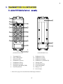
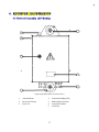
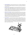
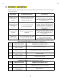
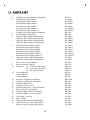
Alpha 3000
Industrial Radio Remote Control System
Operation & Parts Manual
Williams Wireless, LLC
13101 Eckles Road, Plymouth, Michigan 48170
Phone: (734) 416 5520 Fax: (734) 416 1907
E - m a i l : [email protected]
TA B L E O F C O N T E N T S
Page
1.
2.
3.
INTRODUCTION .......................................................................................................
SAFETY INSTRUCTION .............................................................................................
TRANSMITTER ILLUSTRATION
3.1 Alpha 3000F Models External Assembly .............................................................
3.2 Alpha 3000F Models Internal Assembly .............................................................
3.3 Alpha 3000D Models External Assembly .............................................................
3.4 Alpha 3000D Models Internal Assembly .............................................................
4. RECEIVER ILLUSTRATION
4.1 External Assembly (All Models) .........................................................................
4.2 Alpha 3000F Models Internal Assembly .............................................................
4.3 Alpha 3000D Models Internal Assembly .............................................................
5. OUTPUT CONTACT DIAGRAM
5.1 Alpha 3000F2 Output Contact .............................................................................
5.2 Alpha 3000F3 Output Contact .............................................................................
5.3 Alpha 3000D2 Output Contact .............................................................................
5.4 Alpha 3000D3 Output Contact .............................................................................
5.5 Alpha 3000D2-A Output Contact .........................................................................
5.6 Alpha 3000D2-A Output Contact .........................................................................
6. SYSTEM CONFIGURATIONS
6.1 Jumper Settings ...................................................................................................
6.2 Security ID Code Settings .....................................................................................
6.3 Frequency (RF) Channel Settings .......................................................................
6.4 Frequency (RF) Channel Table ...........................................................................
6.5 Pushbutton Contact Settings .................................................................................
6.6 Voltage Settings .....................................................................................................
7. RECEIVER INSTALLATION
7.1 Preparation For Installation ...................................................................................
7.2 Step By Step Installation .......................................................................................
7.3 System Testing .......................................................................................................
8. TRANSMITTER OPERATION ...................................................................................
9. TROUBLE SHOOTING ...............................................................................................
10. SYSTEM SPECIFICATION .........................................................................................
11. PARTS LIST .................................................................................................................
1
2
3
4
5
6
7
8
9
10
11
12
13
14
15
16
17
18~19
19
20
21
22
23
23
24
25~26
27
28
29
1 . I N TR O D U C T I O N
The Alpha 3000 series are highly durable, reliable, and safe industrial radio remote control system. The
versatile features of the Alpha 3000 series permit their usage in many different radio remote control
applications that required 1-step to 3-step pushbutton controls. The system can be used to control tower
cranes, factory cranes, monorail systems, multiple hoists, trolleys, mining equipment, building construction
equipment, automatic control systems, and many others.
The Alpha 3000 radio remote control systems incorporate numerous redundant safety circuits that guaranty
maximum security and ensure the system is resistant to outside interference. The major features of the
Alpha 3000 series are as follow:
*
The system uses advanced 16+1bit microprocessor control with highly evolved software that has
redundant error checking and correcting capabilities to ensure 100% error-free transmission,
decoding, and control of all output relays. This highly evolved software includes CRC (cyclical
redundancy check codes) and Hamming Codes (error recovery) programming.
*
To insure maximum operating safety, the Alpha 3000 system incorporates numerous important safety
features. Some of these built-in safety features include transmitter pushbutton self-diagnosing during
initial startup, transmitter low-voltage detection and warning, receiver self-diagnosing, and MAIN
deactivation when the transmitter is not in use (programmable).
*
The transmitter encoder and receiver decoder both utilize advanced microprocessor control. The
availability of 65,536 sets of unique ID codes will ensure that only commands from the matching
control transmitter can be carried out without any interference from other radio systems.
*
For added safety, the system also incorporates special type of safety MAIN relay. If the safety MAIN
relay becomes defective (fails to open or close during operation), it will signal the central system to
shut down immediately to avoid the possibility of any accidents occurring.
*
30 sets of user-adjustable receiving RF channels via simple dip-switch settings.
*
100% waterproofed transmitter and receiver enclosures (IP66 rated), including the battery
compartment.
Each Alpha 3000 series radio remote control system consists of a water-resistant IP66 handheld transmitter
and receiver. The transmitter casing is molded using industrial strength composite materials (Nylon +
Fiberglass) which are impervious to dust, water, oil, acids, alkaline, heat, sunlight and as well as being
resistant to deformation due to long term use in harsh environments. The industry’s best 2 & 3-step
pushbuttons are also constructed from industrial strength composite materials with a minimum of up to one
million press cycles. For power savings, the transmitter is designed with an ultra high efficiency power
saving circuit that requires only four “AA” size alkaline batteries for more than 250 hours of continuos
operation between battery replacements.
2
2 . S AF E T Y I N S TR U C T I O N
The Alpha 3000 system is relatively simple to use, however, it is very important to observe the proper
safety procedures before, during, and after operation. When used properly our Alpha 3000 series remote
controls will enhance safety, productivity and efficiency in the workplace.
The following procedures should be strictly followed:
1.
Check the transmitter casing and pushbuttons daily. Should any damage that could inhibit the proper
operation of the transmitter be found the unit should be immediately removed from service.
2.
The transmitter voltage should be checked on a daily basis. If the voltage is low (red status light
blinking - refer to page 25), the four “AA” alkaline batteries should be replaced.
3.
The red emergency stop button (EMS) should be checked at the beginning of each shift to ensure it is
in proper working order and the Stop command is being received.
4.
In the event of an emergency, push down the emergency stop button (EMS) immediately to deactivate
the receiver MAIN relay. Then turned the power “off” from the main power source to the crane or
equipment.
5.
The transmitter power key should be pulled “off” after each use and should never leave the transmitter
in the power “on” position when the unit is unattended.
6.
Do not use the same RF channel and ID code as any other system in use at the same facility or within
distance of 900 feet.
7.
Ensure the shoulder strap is worn at all time during operation to avoid accidental damage to the
transmitter.
8.
Never operate a crane or equipment with two transmitter units at the same time with the same RF
channel and ID code.
Caution!
Improper Storage of your Spare Transmitter is a Safety Hazard! During the initial installation of
your remote control system the spare (second) transmitter should be tested to confirm that it is
functioning properly and then the batteries must be removed and the transmitter stored in a secured
place. Failure to follow this safety procedure can result in the inadvertent operation of your crane or
hoist by unauthorized personnel resulting in serious injury or death!
3
3 . T R A N S M I T T E R I L L U S TR AT I O N
3.1 Alpha 3000F Models External
Assembly
1
15
2
3
8
4
9
5
10
6
11
START
AUX
7
12
6
1
13
17
14
(Transmitter Front View)
1.
2.
3.
4.
5.
6.
7.
8.
(Transmitter Back View)
Transmitter Unit
Status LED Display*
Spare Power Key
Pushbutton #2 (Down)
Pushbutton #4 (West)
Pushbutton #6 (South)
Emergency Stop Button (EMS)
Power Key Switch
9.
10.
11.
12.
13.
14.
15.
16.
17.
Pushbutton #1 (Up)
Pushbutton #3 (East)
Pushbutton #5 (North)
Pushbutton #7 (START/AUX)
Warning Label
Shoulder Strap Ring
System Information
Battery Cover
FCC/IC Label
* Please refer to page 25 for transmitter Status LED display information
4
3.2 Alpha 3000F Models Internal A s s e m b l y
1
5
2
6
3
9
1
23 4 5 6 7 8
8
7
10
11
4
(PCB Front View)
1.
2.
3.
4.
5.
(PCB Back View)
Status LED Display
RF-to-Encoder Board Connector
1, 2 or 3-Step Pushbuttons
Emergency Stop Button (EMS)
Power ON/OFF Micro-Switch
6.
7.
8.
9.
10.
11.
5
(RF Board Front View)
Battery Power Connector
ID Code Soldering Slot (1st ~ 8th digit)
ID Code Dip-switch (9th~16th digit)
Internal Antenna
Transmitting RF Board
Quartz Crystal
3.3 Alpha 3000D Models External
Assembly
1
9
1
2
3
10
4
D
U
11
5
W
E
12
6
S
N
13
7
14
8
15
9
16
0
2
17
1
2
18
(Transmitter Front View)
1.
2.
3.
4.
5.
6.
7.
8.
9.
10.
(Transmitter Back View)
Transmitter Unit
Status LED Display*
Spare Power Key
Pushbutton #2 (Down)
Pushbutton #4 (West)
Pushbutton #6 (South)
Pushbutton #8 (AUX)
Pushbutton #10 (AUX)
Emergency Stop Button (EMS)
Power Key Switch
11.
12.
13.
14.
15.
16.
17.
18.
19.
20.
21.
Pushbutton #1 (Up)
Pushbutton #3 (East)
Pushbutton #5 (North)
Pushbutton #7 (AUX)
Pushbutton #9 (AUX)
Pushbutton #11 (START/AUX)
Warning Label
Shoulder Strap Ring
System Information
Battery Cover
FCC/IC Label
* Please refer to page 25 for transmitter Status LED display information
6
3.4 Alpha 3000D Models Internal A s s e m b l y
1
5
2
6
3
9
7
1
23 4 5 6 7 8
8
10
11
4
(PCB Front View)
1.
2.
3.
4.
5.
(PCB Back View)
Status LED Display
RF Board to Encoder Board Connector
1, 2 or 3-Step Pushbuttons
Emergency Stop Button (EMS)
Power ON/OFF Micro-Switch
6.
7.
8.
9.
10.
11.
7
(RF Board Front View)
Battery Power Connector
ID Code Soldering Slot (1st ~ 8th digit)
ID Code Dip-switch (9th~16th digit)
Internal Antenna
Transmitting RF Board
Quartz Crystal
4 . R E C E I V E R I L L U S TR AT I O N
4.1 E x t e r n a l A s s e m b l y ( A l l M o d e l s )
5
1
2
3
4
6
7
(Alpha 3000 Models Receiver External View)
1.
2.
3.
Antenna Mount
Receiver Enclosure
Key Lock
4.
5.
6.
7.
8
External Grounding Hole
Rubber Shock Absorber
System Information
Cord Grip
4.2
Alpha 3000F Models Internal A s s e m b l y
1
2
3
4
0
1
5
6
7
1
2
1
8
U1 D1
U2
+
D2
U3
+
D3
E1 W1
E2
+
W2
E3
+
W3
N1 S1
N2
+
S2
3
1
N3
+
S3
4
1
9
Z1
ID
~ ~
1
5
6
1
(Alpha 3000F Models Receiver Internal View)
1.
2.
3.
4.
5.
6.
7.
8.
*
Antenna Seat
Receiving RF Module
Decoder Module
Decoder Module Power Display
Receiver Status LED Display*
SQ Status LED Display*
Power (AC) LED Display
Upper Relay Board
9.
10.
11.
12.
13.
14.
15.
16.
Bottom Relay Board
Power Transformer
Input Voltage Selector Seat
Contact Relay LED Display
Terminal Block
Power Fuses (1.0A)
AC Power Input
MAIN Contact Relay
Please refer to page 27 for Receiver and SQ display information
9
4.3
Alpha 3000D Models Internal A s s e m b l y
1
2
3
4
0
1
5
6
7
1
2
1
8
U1 D1
U2
+
D2
U3
+
D3
E1 W1
E2
+
W2
E3
+
W3
N1 S1
N2
+
S2
3
1
N3
+
S3
4
1
9
AU2
+
AD2
AU3
+
AD3
X1 Y1
X2+Y2
(X2)
X3 +Y3
(Y2)
Z1
ID
~ ~
1
5
6
1
(Alpha 3000D Models Receiver Internal View)
1.
2.
3.
4.
5.
6.
7.
8.
Antenna Seat
Receiving RF Module
Decoder Module
Decoder Module Power Display
Receiver Status LED Display*
SQ Status LED Display*
Power (AC) LED Display
Upper Relay Board
9.
10.
11.
12.
13.
14.
15.
16.
*
Please refer to page 27 for Receiver and SQ display information
10
Bottom Relay Board
Power Transformer
Input Voltage Selector Seat
Contact Relay LED Display
Terminal Block
Power Fuses (1.0A)
AC Power Input
MAIN Contact Relay
5. OUTPUT CONTACT DIAGRAM
5.1
Alpha 3000F2 Output Contact
K13
K14
K15
U1
D1
U2
+
D2
E1
W1
E2
+
W2
J1 5
N1
S1
N2
+
S2
UPPER RELAY BOARD
Z1
RES
ID
MAIN
AC
BOTTOM RELAY BOARD
Note:
Z1 output contact represents the 7th pushbutton on the transmitter (START/AUX), which can be
used for lights, horn, or other types of applications (refer to section 6.5 on page 21).
Terminal Block and Common Shorting Pin Assembly
Common shorting pin illustrated above can be used rather than “daisy chaining” wiring for the common.
11
5.2
U1
Alpha 3000F3 Output Contact
D1
U2
+
D2
U3
+
D3
E1
W1
E2
+
W2
E3
+
W3
N1
S1
N2
+
S2
N3
+
S3
UPPER RELAY BOARD
Z1
RES
ID
MAIN
BOTTOM RELAY BOARD
Note:
Z1 output contact represents the 7th pushbutton on the transmitter (START/AUX), which can be
used for lights, horn, or other types of applications (refer to section 6.5 on page 21).
Terminal Block and Common Shorting Pin Assembly
Common shorting pin illustrated above can be used rather than “daisy chaining” wiring for the common.
12
5.3
U1
Alpha 3000D2 Output Contact
D1
U2
+
D2
E1
W1
E2
+
W2
N1
S1
N2
+
S2
UPPER RELAY BOARD
AU1
AD1
AU2
+
AD2
X1
Y1
Z1
X2+Y2
RES
MAIN
ID
BOTTOM RELAY BOARD
Note A:
Note B:
Note C:
AU & AD output contacts represent the 7th and 8t h pushbuttons on the transmitter (AUX_&
AUX_), which can be used for the auxiliary hoist motion or other types of applications (refer to
section 6.5 on page 21).
X & Y output contacts represent the 9th and 10th pushbuttons on the transmitter (AUX & AUX),
which can be used for the auxiliary trolley motion or other types of applications (refer to section
6.5 on page 21).
Z1 output contact represents the 11th pushbutton on the transmitter (START/AUX), which can be
used for lights, horn, or other types of applications (refer to section 6.5 on page 21).
Terminal Block and Common Shorting Pin Assembly
Common shorting pin illustrated above can be used rather than “daisy chaining” wiring for the common.
13
5.4
U1
Alpha 3000D3 Output Contact
D1
U2
+
D2
U3
+
D3
E1
W1
E2
+
W2
E3
+
W3
N1
S1
N2
+
S2
N3
+
S3
UPPER RELAY BOARD
AU1
AD1
AU2
+
AD2
AU3
+
AD3
X1
Y1
X2+Y2
(X2)
X3+Y3
(Y2)
Z1
RES
MAIN
ID
BOTTOM RELAY BOARD
Note A:
Note B:
Note C:
AU & AD output contacts represent the 7th and 8t h pushbuttons on the transmitter (AUX_&
AUX_), which can be used for the auxiliary hoist motion or other types of applications (refer to
section 6.5 on page 21).
X & Y output contacts represent the 9th and 10th pushbuttons on the transmitter (AUX & AUX),
which can be used for the auxiliary trolley motion or other types of applications (refer to section
6.5 on page 21).
Z1 output contact represents the 11th pushbutton on the transmitter (START/AUX), which can be
used for lights, horn, or other types of applications (refer to section 6.5 on page 21).
Terminal Block and Common Shorting Pin Assembly
Common shorting pin illustrated above can be used rather than “daisy chaining” wiring for the common.
14
5.5
U1
Alpha 3000D2-A Output Contact
D1
U2
+
D2
E1
W1
E2
+
W2
N1
S1
N2
+
S2
UPPER RELAY BOARD
AU1
AD1
X1
Y1
Z1
RES
MAIN
ID
BOTTOM RELAY BOARD
Note A:
Note B:
Note C:
AU & AD output contacts represent the 7th and 8th pushbuttons on the transmitter (AUX_&
AUX_), which can be used for the auxiliary hoist motion or other types of applications (refer to
section 6.5 on page 21).
X & Y output contacts represent the 9th and 10th pushbuttons on the transmitter (AUX & AUX),
which can be used for the auxiliary trolley motion or other types of applications (refer to section
6.5 on page 21).
Z1 output contact represents the 11th pushbutton on the transmitter (START/AUX), which can be
used for lights, horn, or other types of applications (refer to section 6.5 on page 21).
Terminal Block and Common Shorting Pin Assembly
Common shorting pin illustrated above can be used rather than “daisy chaining” wiring for the common.
15
5.6
U1
Alpha 3000D3-A Output Contact
D1
U2
+
D2
U3
+
D3
E1
W1
E2
+
W2
E3
+
W3
N1
S1
N2
+
S2
N3
+
S3
UPPER RELAY BOARD
AU1
AD1
X1
Y1
Z1
RES
MAIN
ID
BOTTOM RELAY BOARD
Note A:
Note B:
Note C:
AU & AD output contacts represent the 7th and 8th pushbuttons on the transmitter (AUX_&
AUX_), which can be used for the auxiliary hoist motion or other types of applications (refer to
section 6.5 on page 21).
X & Y output contacts represent the 9th and 10th pushbuttons on the transmitter (AUX & AUX),
which can be used for the auxiliary trolley motion or other types of applications (refer to section
6.5 on page 21).
Z1 output contact represents the 11th pushbutton on the transmitter (START/AUX), which can be
used for lights, horn, or other types of applications (refer to section 6.5 on page 21).
Terminal Block and Common Shorting Pin Assembly
Common shorting pin illustrated above can be used rather than “daisy chaining” wiring for the common.
16
6 . S Y S T E M C O N F I G U R AT I O N S
6.1
J u m p er S e t t i n g s
There are numerous functions that can be set via jumpers located inside the decoder module. Please see
the diagram and chart below on how to set these
functions.
Manufacture Setting
Open
After inserting the transmitter power key at system startup, or after EMS
reset, press and hold START/AUX to activate the receiver MAIN relay.
Short
Insert the transmitter power key will immediately activates the receiver
MAIN relay. After EMS reset, re-insert the power key to reactivate the receiver
MAIN relay.
Open
After 5 minutes of transmitter non-usage the receiver MAIN relay will be
deactivated.
Short
Receiver MAIN relay stays on constantly until the main power source to the
system is turned off.
Open
Pushbutton #1 through #6 interlocked (U/D, E/W, N/S).
Short
Pushbutton #1 through #6 non-interlocked with single-speed relay contact.
Open
No acceleration delay from 1st through 3rd speed (F3 & D3 models only).
Short
Acceleration delay for up to 1 second from 1st through 3rd speed
(F3 & D3 models only).
JP1
JP2
JP3
JP4
Note:
Every time when you change jumper settings you must first turn the receiver power “off” and then turn it
back “on” after setting so that they can be stored in memory.
JP1
JP1
Open
Insert the transmitter
power key
Press and hold
START/AUX
JP1
Short
Insert the transmitter
power key
Receiver MAIN
activated
Receiver MAIN
activated
OR
OR After EMS reset
After EMS
reset
Press and hold
START/AUX
Re-insert the transmitter
power key
Receiver MAIN
activated
Receiver MAIN activated
JP2
JP2
Open
JP2
Short
5 minutes of transmitter non-usage
Receiver MAIN deactivated
Press any pushbuttons
Receiver MAIN reactivated
Receiver MAIN stays “on” constantly until the main power source to the system is turn “off”
17
JP3
JP3
Open
Pushbutton 1 through 6 interlocked
JP3
Short
Pushbutton 1 through 6 non-interlocked with each pushbutton becomes single-speed contact
JP4 (F3 & D3 models only)
JP4
Open
JP4
Short
6.2
No acceleration delay from 1st through 3rd speed (Alpha 3000F-3 & D-3 models only)
1st speed
pressed
After 1
second
1st speed contact
relay engaged
2nd speed
pressed
After 1
second
2nd speed contact
relay engaged
3rd speed
pressed
After 1
second
3rd speed contact
relay engaged
Security ID Code Settings
Transmitter ID code can be readjusted via an 8-position soldering slot (the first 8 digits of the ID code) and
an 8-position dip-switch (the last 8 digits of the ID code). Please refer to item # 7 on page 5 and item # 8
on page 7 for the location of the soldering slot and dip-switch on the encoder board. As for the receiver ID
code setting, the soldering slot and the dip-switch are located inside the decoder module; please refer to
item #3 on page 9 & 10 and below
illustration.
(Decoder module internal view)
Please note that the first 8 digits of the ID code can be changed by soldering the two points together (“1”
value); the position is at “0” value when left unsoldered (two points open). The last 8 digits of the ID code
are set via an 8-position dip-switch located next to the 8-position soldering slot.
18
Due to Alpha 3000 series’ ID code (or address code) is 16-digit long, the first 8 digits are set via the
soldering slot and the remaining last 8 digits are set via the dip-switch (total of 16 digits). For the soldering
slot, the “SH8” represents the 1st digit of the ID code and “SH15” represents the 8th digit of the ID code. As
for the dip-switch, the “1” represents 9th digit of the ID code and the “8” represents the 16th digit of the ID
code (last digit). Below are some sample illustrations for better understanding on how to set the entire 16digit ID code via the soldering slot and the dip-switch.
Example 1:
ID code 00000000:10101010
Example 2:
ID code 01011001:00011100
6.3
Frequency (RF) Channel Settings
All Alpha 3000 systems are also equipped with a PLL synthesized receiving RF module with up to 30 useradjustable RF channels. The RF channel dip-switch is located on the topside of the receiving RF module,
covered by a sliding door (refer to item #2 on page 9 & 10).
Example: For the below illustrated dip-switch “00101” setting, counting from dip-position #1 through #5,
the RF channel would be “205”, which also represents frequency “301.205 MHz”. Please refer
to the Frequency (RF) Channel Table next page or the CHANNEL _ DIP label inside the
receiver door panel.
Top Location
_ “1”
Bottom Location _ “0”
19
6.4
Frequency (RF) Channel Table
FREQUENCY
DIP-SWITCH SETTING
RF CHANNEL
301.105 MHz
00001
201
301.130 MHz
00010
202
301.155 MHz
00011
203
301.180 MHz
00100
204
301.205 MHz
00101
205
301.230 MHz
00110
206
301.255 MHz
00111
207
301.280 MHz
01000
208
301.305 MHz
01001
209
301.330 MHz
01010
210
301.355 MHz
01011
211
301.380 MHz
01100
212
301.405 MHz
01101
213
301.430 MHz
01110
214
301.455 MHz
01111
215
301.480 MHz
10000
216
301.505 MHz
10001
217
301.530 MHz
10010
218
301.555 MHz
10011
219
301.580 MHz
10100
220
301.605 MHz
10101
221
301.630 MHz
10110
222
301.655 MHz
10111
223
301.680 MHz
11000
224
301.705 MHz
11001
225
301.730 MHz
11010
226
301.755 MHz
11011
227
301.780 MHz
11100
228
301.805 MHz
11101
229
301.830 MHz
11110
230
20
6.5
Pushbutton Contact Settings
There are numerous pushbutton functions that can be programmed via an 8-position dip-switch located on
the decoder module (refer to the diagram below). By adjusting each dip setting either to the top or bottom
location will change the contact form of the intended pushbutton (refer to the chart below). Transmitter
pushbuttons are numbered from right-to-left and then from top-to-bottom.
Alpha 3000F
Models
Top Location
_
“1”
Bottom Location
_
“0”
DIP1 _ “0” _ Pushbutton #7 (START/AUX) with momentary relay contact
“1” _ Pushbutton #7 (START/AUX) with latching relay contact
DIP1 _ “0” _ Pushbutton #11 (START/AUX) with momentary relay contact
“1” _ Pushbutton #11 (START/AUX) with latching relay contact
DIP2 _ “0” _ Pushbutton #7 & #8 interlocked
“1” _ Pushbutton #7 & #8 non-interlocked
DIP3 _ “0” _ Pushbutton #7 with momentary relay contact*
“1” _ Pushbutton #7 with latching relay contact*
* DIP2 must set to “1”
Alpha 3000D
Models
DIP4 _ “0” _ Pushbutton #8 with momentary relay contact*
“1” _ Pushbutton #8 with latching relay contact*
* DIP2 must set to “1”
DIP5 _ “0” _ Pushbutton #9 & #10 interlocked
“1” _ Pushbutton #9 & #10 non-interlocked
DIP6 _ “0” _ Pushbutton #9 with momentary relay contact*
“1” _ Pushbutton #9 with latching relay contact*
* DIP5 must set to “1”
DIP7 _ “0” _ Pushbutton #10 with momentary relay contact*
“1” _ Pushbutton #10 with latching relay contact*
* DIP5 must set to “1”
21
6.6 V o l t a g e S e t t i n g s
There are four different voltage settings available inside the Alpha 3000 receiver located next to the bottom
relay board, please select one that corresponds to the main power source of the crane or equipment.
Power Transform Available:
SSB-2181
_
48VAC / 220VAC / 0ACV / 460VAC @ 50/60Hz.
SSB-1726
_
110VAC / 220VAC / 380VAC / 415VAC @ 50/60Hz.
SSB-2213
_
115VAC / 208VAC / 230VAC / 460VAC @ 50/60Hz.
Note A:
When different voltage setting is selected, make sure that one end of the wire is connected to the COM
position and the other end connected to the voltage position that corresponds to the main power source of
the crane or equipment. Also make sure that all screws are tightened prior to turning “on” the main power
supply.
Note B:
If the receiver system does not respond when the main power source is turn on, then turn the power off and
check for any burned or open fuse.
22
7 . R E C E I V E R I N S TA L L AT I O N
7.1
Preparation For Installation
1.
Required Tools:
(1)
Flat Head Screwdriver (-)
(2)
Phillips Head Screwdriver (+)
(3)
Multi-Meter
(4)
Open End Wrench
(5)
Power Drill with 10.5mm ~ 11mm Drill-Bit
2.
Check to ensure that your receiver is not set to the same RF channel and ID code as any other
systems in operation at the same facility or within distance of 900 feet.
3.
Prior to installation, make sure that the crane or equipment itself is working properly.
4.
Use a multi-meter to check the voltage source available and ensure that the receiver voltage
setting matches your power source.
5.
Prior to installation, switch “off” the main power source to the crane or equipment.
7.2
Step By Step Installation
1.
The location selected should have the antenna visible from all areas where the transmitter is to
be used.
2.
The location selected should not be exposed to high levels of electrical noise.
3.
Ensure the selected location has adequate space to accommodate the receiver enclosure.
4.
Make sure the receiver unit is in upright position (vertical).
5.
The distance between the antenna and the control panel should be as far apart as possible.
6.
Drill two holes on the control panel (10.5mm). Refer to diagrams next page.
7.
Tightened the bolt nuts provided.
8.
Ensure AC ground is connected to the power input terminal block, otherwise chassis
ground should be connect to the chassis ground connection hole on the receiver enclosure
(refer to item #4 on page 8).
9.
For system wiring, please refer to the output contact diagram on page 11~16.
10. Ensure all wiring is correct and safely secured and all screws are fastened.
23
7.3
System Testing
1.
Connect the power source to the receiver and test the MAIN relay output (EMS button) and
observe that it properly opens and closes the main line.
2.
Test the operation of each function to ensure it corresponds to the transmitter direction
labels and/or the pendant it is replacing.
3.
Test the limit switches on the crane and verify that they are working properly.
4.
If your new remote control is replacing an existing pendant make sure it is completely
disconnected to prevent unwanted control commands.
5.
If your new remote control is replacing an existing pendant make sure the pushbutton is
stored in a safe location where it will not interfere with remote operation.
24
8.. T R A N S M I T T E R O P E R AT I O N
1.
Batteries _ Make sure the four “AA” alkaline batteries are installed correctly, the labels on the battery
holder will tell you which side is “up” and which side is “down”. Use 2,000mA alkaline type batteries
for optimum operating time between replacements. If rechargeable batteries are used, for optimum
operating time between replacements, select ones rated 1,600mA or above.
2.
Startup Procedure _ You must first make sure that the red
EMS button is elevated prior to inserting the transmitter power
key, by pulling it upward. Then insert the power key into the
key-slot located on the top right-hand side of the transmitter
(refer to diagram to the right). The transmitter status LED on
the top-center location of the transmitter will display a
constant green light for up to 2 seconds when the power key is
inserted. Then press and hold the START/AUX pushbutton
for up to 1.0 second to activate the receiver MAIN relay
(depending on JP1 setting on page 17). Thereafter, the
START/AUX pushbutton becomes an auxiliary function, which can be used for lights, horn, etc…
When a command pushbutton is pressed, the Status LED will display a blinking green light informing
the operator that the command signals are being transmitted. Please refer to the table below for
transmitter status LED display information.
3.
Transmitter Status LED Display (refer to item #2 on page 4 & 6)
TYPE
LED DISPLAY
INDICATION
1
Green “on” _ 2.0 seconds
System initial power “on”
2
3
4
5
Green “on” _ 0.1 second
“off” _ 2.0 seconds
Red “on” _ 0.1 second
“off” _ 2.0 seconds
2 fast red blinks followed
by 2 seconds “off”
Pushbutton pressed with signal transmitted
Transmitter low-voltage warning
Pushbutton contact jammed or locked
Red “on” _ 0.5 second
“off” _ 0.5 second
Emergency stop button activated (pressed down)
4.
Receiver Main Relay Deactivates in 5 Minutes _ Your receiver MAIN relay is programmed to drop
(open) the “Main Line Disconnect Contactor” after 5 minutes of inactivity, that is 5 minutes after the
last pushbutton is released. Pressing any pushbutton will close the MAIN relay and start the timing
sequence over again. If your crane or hoist is equipped with VFD drive this can sometimes cause an
unacceptable delay. In this situation we suggest you remove the JP2 jumper (refer to JP-2 setting on
page 17) then the MAIN relay will remain closed until the “Stop” command is received or the main
power source to the equipment is turned off.
5.
EMS & Restarting _ In case of an emergency, pressing down the red EMS button will immediately
deactivates the receiver MAIN relay. When EMS button is activated (depressed), the transmitter
status LED will display a red blinking lights that is “on” _ 0.5 second and “off” _ 0.5 second (refer to
the chart above). To reactivate the receiver MAIN relay, just pull up the red EMS button and then
press and hold START/AUX pushbutton for up to a second (depending on JP1 setting on page 17).
25
6.
Interlocking Pushbuttons _ For both F & D models, the top 3 sets of motions are interlocked to its
self so no conflicting commands can take place for safety purpose. For example, pressing the hoist
“UP” and “DOWN” pushbutton simultaneously will result in no command being sent (depending on
JP3 setting on page 17).
7.
Initial Start-up Code_ Please note that, if JP1 is shorted (without START function), the receiver unit
hence must received an “Initial Startup Code” from the transmitter in order for it’s MAIN relay to
be energized. What this means is that the transmitter can only activate the receiver MAIN relay as
long as the operator is within the receiving range. For example, if the operator turned “on” the
transmitter in a different area of the facility (beyond 300 feet from the receiver location), then he will
not be able to control the crane when he approached within 300 feet. If this happens, the operator
would have to resent the initial startup code by reenact the Startup Procedure.
8.
Shutting Off the Transmitter _ To disconnect the transmitter power, just pull out the transmitter
power key. It is also recommended that prior to disconnecting the transmitter power, also activate the
emergency stop by pressing down the red EMS button, this will deactivate the receiver MAIN relay.
After the red EMS button is depressed, then pull out the transmitter power key. Please note that if the
power key is not pulled out after EMS activation, then the transmitter will continued to send the
“Stop” command to the receiver until the transmitter power is completely drained. Also, if the red
EMS button is not depressed prior to disconnecting the transmitter power, the receiver MAIN relay
will still drop (open) after 5 minutes (depending on JP2 setting on page 17).
9.
Battery Replacement _ The transmitter Status LED will display a blinking red light that is “on” 0.1
second and off “2.0 seconds when the transmitter battery power falls below the safety operating
voltage, please refer to the table on page 25 for transmitter status LED display information. For
battery replacement, just unscrew the battery cover located on the backside of the transmitter handset
with a (+) head screwdriver (refer to the diagram below). When changing batteries, do make sure that
the batteries are installed correctly. The marking inside the battery holder will tell you which side is
positive (+) and which side is negative (-). The battery holder will also tell you which side of the
holder is facing up and which side is down.
26
9 . T R O U B L E S H O OT I N G
Should the operator find the equipment not operating normally, please check the chart below for simple
trouble shooting tips.
PROBLEM
POSSIBLE REASON
SOLUTION
Transmitter does not
communicate to
receiver.
Transmitter and the receiver are
not on the same RF channel
(SQ not lit) or ID code.
Ensure the correct transmitter is in use.
The labels on the receiver and the
transmitter will identify the RF channel
and ID code in use.
Transmitter does not
communicate to
receiver.
Low or no transmitting power
from the transmitter unit.
Turn on the transmitter with EMS button
elevated. If the status LED displayed a
blinking red lights or no lights at all,
then turn the power off and replace the
four batteries.
No power to the
receiver.
Blown fuse or no input power
connection.
Ensure power input to the receiver unit
is correct. If power indicator (AC) is
not lit, please check the receiver for
any open fuse.
Outputs do not
operate correctly.
Receiver configuration and output
wiring is not set properly.
Please refer to section 5 and 6 to ensure
receiver is correctly wired
and configured for your application.
Receiver Status LED Display (refer to item #5 on page 9 & 10)
TYPE
LED INDICATION
PROBLEM AND SOLUTION
1
3 fast blinks followed by
OFF _ 2.0 seconds
Defective MAIN contact relay.
2
2 fast blinks followed by
OFF _ 2.0 seconds
Incorrect ID code setting, please refer to section 6.2.
3
ON _ 0.1 second
OFF _ 2.0 seconds
Decoder on standby.
4
ON _ 0.1 second
OFF _ 0.1 second
Transmitted signal decoded.
SQ Status LED Display (refer to item #6 on page 9 & 10)
TYPE
LED INDICATION
PROBLEM AND SOLUTION
1
ON _ 0.1 second
OFF _ 0.1 second
Transmitted signal received by the receiver.
2
Blinking when pushbuttons
are not pressed
Radio interference.
27
1 0 . S Y S T E M S P E C I F I C AT I O N
Transmitter Unit
Frequency Range
Transmitting Range
Hamming Distance
Channel Spacing
Frequency Control
Frequency Drift
Frequency Deviation
Spurious Emission
Transmitting Power
Emission
Antenna Impedance
Enclosure
Source Voltage
Current Drain
Operating Temp.
Dimension
:
:
:
:
:
:
:
:
:
:
:
:
:
:
:
:
Weight (include batteries)
:
301MHz
300 feet
_6
25KHz
Quartz Crystals
< 5ppm @ -13_ ~ 158_
< 1ppm
-50dB
~0.3mW
F1D
50 ohms
IP-66
DC 6.0V
8mA @ 6V
-13_ ~ 158_
9.0in x 3.0in x 1.85in (Alpha 3000F Models)
11.5in x 3.0in x 1.85in (Alpha 3000D Models)
21oz (Alpha 3000F Models)
25.7oz (Alpha 3000D Models)
Receiver Unit
Frequency Range
Demodulation
Frequency Control
Frequency Drift
Frequency Deviation
Sensitivity
Antenna Impedance
Data Decoder Reference
Responding Time
Enclosure
Source Voltage
Power Consumption
Operating Temp.
Output Contact Rating
Dimension
Weight (include antenna)
:
:
:
:
:
:
:
:
:
:
:
:
:
:
:
:
301MHz
Narrow Band FM
Synthesizer (PLL)
< 5ppm @ -13_ ~ 158_
< 1ppm
-122dBm
50ohms
Quartz Crystals
64~100mS
IP-66
AC 110V/220V/380V/415V @ 50/60 Hz.
11VA
-13_ ~ 158_
250V @ 10A
16.7in x 9.6in x 5.1in (All Models)
17.7lb (All Models)
28
1 1 . PARTS L I S T
1.
2.
3.
4.
5.
6.
7.
8.
9.
10.
11.
12.
13.
14.
15.
16.
17.
18.
19.
20.
21.
22.
23.
301MHz. Transmitting RF Board (All Models)
Encoder Board (Alpha 3000F2)
Encoder Board (Alpha 3000F3)
Encoder Board (Alpha 3000D2)
Encoder Board (Alpha 3000D3)
Encoder Board (Alpha 3000D2-A)
Encoder Board (Alpha 3000D3-A)
301MHz. Receiving RF Module (All Models)
Decoder Module (All Models)
Upper Rely Board (Alpha 3000F2 Models)
Upper Rely Board (Alpha 3000F3 Models)
Upper Rely Board (Alpha 3000D2 Models)
Upper Rely Board (Alpha 3000D3 Models)
Bottom Relay Board (Alpha 3000F2)
Bottom Relay Board (Alpha 3000F3)
Bottom Relay Board (Alpha 3000D2)
Bottom Relay Board (Alpha 3000D3)
Bottom Relay Board (Alpha 3000D2-A)
Bottom Relay Board (Alpha 3000D3-A)
Transmitter Casing (Alpha 3000F Models)
Transmitter Casing (Alpha 3000D Models)
Receiver Enclosure (All Models)
Receiver Antenna (301MHz)
Transformer (AC - 110V/220V/380V/415V)
(AC - 115V/208V/230V/460V)
(AC - 48V/220V/0V/460V)
1-Step Pushbutton
2-Step Pushbutton
3-Step Pushbutton
Emergency Stop Button (All Models)
Emergency Stop Red Cap (All Models)
Pushbutton Rubber Boot
Pushbutton Compass Label
Transmitter Power Key + Strap (All Models)
Receiver Panel Key (All Models)
Transmitter Battery Holder (All Models)
Transmitter Battery Cover (All Models)
Cable Gland / Cord Grip
Shock Absorber
Transmitter Shoulder Strap (Both Models)
Protective Vinyl Covering (Alpha 3000F)
Protective Vinyl Covering (Alpha 3000D)
29
TX-2005
EN-3000F2
EN-3000F3
EN-3000D2
EN-3000D3
EN-3000D2A
EN-3000D3A
RX-3000
DE-3000
RY-3000F2
RY-3000F3
RY-3000D2
RY-3000D3
RY-3001F2
RY-3001F3
RY-3001D2
RY-3001D3
RY-3001D2A
RY-3001D3A
TC-3000F
TC-3000D
RC-3000
ANT-301
SSB-1726
SSB-2213
SSB-2181
PB-3001
PB-3002
PB-3003
EMS-3000
RD-3000
RB-3000
DL-3000
TK-3000
RK-3000
BH-3000
BC-3000
CG-3000
SA-3000
SS-3000
PC-3000F
PC-3000D