1
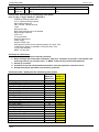
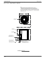
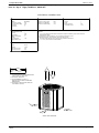
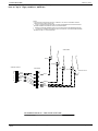
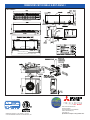
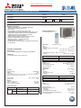
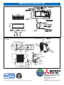
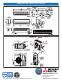
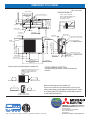
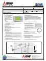
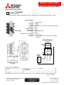
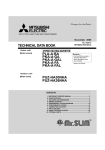
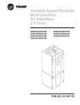
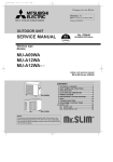
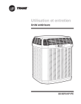
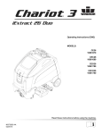
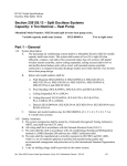
®
HESS MECHANICAL CORPORATION
9600 Fallard Court
Upper Marlboro, Maryland 20772
(301) 856-4700 Phone
(301) 856-4720 Fax
LETTER OF TRANSMITTAL
To:
Attention:
Hess Construction
804 West Diamond Avenue. Suite 300
Gaithersburg, Maryland 20878
Eileen B. Panasewicz
Date:
Reference:
4/8/13
Loudoun County HS No. 6
HMC Project No.:
576
WE ARE SENDING YOU:
X
Attached
the following items:
Shop Drawings
Prints
Subcontract
Copy of Letter
Change Order
Samples
Certification
Payroll
RFI
Copies
Electronic
X
Under Separate Cover via
For Approval
For Your Use
As Requested
Date
4/8/13
Number
S-07
For Review &
Comment
Approved as
Submitted
Approved as
Noted
X
Purchase Order
Specifications
Mfr’s Data
Plans
Submittals
Other
Description
Split System A/C units
Make Corrections
Noted
Revise & Resubmit
Rejected
Resubmit 14 copies
for approval
Return 4 copies
for distribution
Return
corrected prints
Prints Returned
After Loan To Us
Signature
Required
Other
REMARKS
Copy To: Field
Signed: __________________________________
®
HESS MECHANICAL CORPORATION
9600 Fallard Court
Upper Marlboro, Maryland 20772
(301) 856-4700 Phone
(301) 856-4720 Fax
Submittal Cover Sheet
To: Hess Construction
Date: 4/8/13
804 West Diamond Avenue. Suite 300
Project: Loudoun County High School No. 6
Gaithersburg, Maryland 20878
Project Number: 0576
Attention: Eileen B. Panasewicz
Reference: Loudoun County HS No.6
HMC Submittal No.:
S-07
Equipment:
Split System A/C units
Specification Section:
23-81-26
Supplier:
Trane
Drawing Number:
M-131
Reviewed By:
Bryan Miesowitz
All units are R 410 A which is HCFC free and meet the EA 4 Credit
This shop drawing has been reviewed and determined to be in compliance with the Contract Documents, including
Plans and Specifications as modified by addenda, change orders, and field orders as of the date of this submittal.
Project Manager
Date
CONSTRUCTION MANAGER’S/ARCHITECT’S REVIEW STAMP:
Quality People. Building Solutions.SM
Updated 05/31/05
Submittal
Prepared For:
2RW Consultants, Inc
th
100 10 St NE, Suite 102
Charlottesville, VA 22902
Date: March 31, 2013
Sold To:
Hess Mechanical
9600 Fallard Court
Upper Marlboro, MD 20772
Job Name:
Loudoun HS 6, LCPS
Trane U.S. Inc. is pleased to provide the enclosed submittal for your review and approval.
Product Summary
Qty
Product
2
Split System Air Conditioning Units (Small)
Contractor Coordination Notes:
#1 Contractor to coordinate disconnect switch sizing per the electrical data submitted within this document
Engineer Coordination Notes:
#1 N/A
Prepared by: Jason Mindlin
Reviewed by: Chris Wood
Trane
30 West Watkins Mill Road
Gaithersburg, MD 20878
Phone: (240) 306-3000
Fax: (240) 306-3300
J:\JOBS\24\132968\5\S-RTU-1,5,6.doc
The attached information describes the equipment we propose to
furnish for this project, and is submitted for your approval.
Table Of Contents
Product Summary .............................................................................. Error! Bookmark not defined.
Split System Air Conditioning Units (Small) (Item A1) ...............................................................3
Tag Data .................................................................................................................................................. 3
Product Data ............................................................................................................................................ 3
Performance Data ..................................................................................... Error! Bookmark not defined.
Mechanical Specifications ........................................................................................................................ 4
Unit Dimensions ....................................................................................................................................... 6
Weight, Clearance & Rigging Diagram................................................................................................... 10
Accessory .............................................................................................................................................. 11
Field Installed Options - Part/Order Number Summary ............................................................12
Split System Air Conditioning Units (Small) ........................................................................................... 12
Loudoun HS 6, LCPS
March 31, 2013
Tag Data - Split System Air Conditioning Units (Small) (Qty: 2)
Item Tag(s)
Qty Description
Model Number
A1
AH/HP-O-1, 2
1 - 6 Ton Unitary Split Systems (
4TWR5049E1000-TAM7A0C48H-1S-0----000
AH/HP-O-2
SSC )
-0--0
Product Data - Split System Air Conditioning Units (Small)
Item: A1 Qty: 2 Tag(s): AH/HP-O-1, AH/HP-O-2
4TWR5 Heat Pump Outdoor Unit
4 Ton - Nominal Cooling Capacity
Major Design Sequence
200 - 230 Volt 1 Phase 60 Hertz
Trane
Multi-poise 4-way
Best, Retail replacement hi eff varspeed
Major designs sequence
23.5 x 21.5
4 Ton air handler
High EFF Multi-speed
Power Supply
System Control Type
Head pressure control for low ambient operation to 0 deg F (Fld)
15 kW Electric Heater for 208/240V 3 Phase 60 Hertz (Fld)
5 Year Parts Warranty
MERV 13 Filter (Fld)
Clarifications & Exclusions:
1. Disconnect switch to be provided by contractor
2. Basis of design AHU comes with a standard 1” filter rack. Contractor to provide 2” external filter rack
with hinged access, per schedule note 7. 2” MERV 13 filter will be provided with equipment
3. Startup by contractor
4. Contractor to provide wall mounted thermostat for each split system per schedule note 12
5. Refrigerant piping & specialties are provided by contractor
Performance Data - Split System Air Conditioning Units (Small)
Tags
Design clg outdoor DB (F)
Cooling EDB (F)
Cooling EWB (F)
Clg net total capacity (Btuh)
Clg net sensible capacity (Btuh)
Calc clg LDB (F)
Calc clg LWB (F)
SEER @ AHRI (btuh/watt)
External static pressure (in wc)
System airflow @ 0.5” ESP (cfm)
ASHRAE 90.1 S6.4.1 compliant
Htg outdoor DB (F)
Heating capacity @ 47F (Btuh)
HSPF @ AHRI (btuh/watt)
Heating EDB (F)
Electric heat capacity @ 208 Volts (kW)
MCA/MOP Indoor Unit
MCA/MOP Outdoor Unit
Weight Indoor Unit (lbs)
Weight Outdoor Unit (lbs)
FLD = Furnished by Trane U.S. Inc. / Installed by
Others
Specified
AH/HP-O-1,
AH/HP-O-2
94
80
67
46700
35400
15
0.5
1600
47
46700
8.5
10.8
42/45
29/50
180
350
Submitted
AH/HP-O-1,
AH/HP-O-2
94.00
80.00
67.00
49960.00
36800.00
58.40
56.70
15.50
0.5
1560
Yes
47.00
47500.00
9.00
64.30
10.8
42/45
28/50
175
331
Equipment Submittal
Page 3 of 12
Loudoun HS 6, LCPS
March 31, 2013
Mechanical Specifications - Split System Air Conditioning Units (Small)
Item: A1 Qty: 2 Tag(s): AH/HP-O-1, AH/HP-O-2
Air-Tite IITM cabinet
- 2% or less air leakage
- Precision applied - durable door seals - Specially designed air seal around
refrigerant, condensate and conduit
connections
- Double wall foamed cabinet system - ¿ R-4.2 insulating value
- No loose fiber design
- Smooth cleanable interior design - Sweat eliminating design
- Composite foamed cabinet doors - Water proof cabinet design
- Integrated horizontal drain pans
- Modular cabinet with 5/16" allen wrench "quick latch" design
Multi-position up/down flow horizontal left/ right
Side return option (sold as accessory)
Control board protection pocket built into cabi-net wall
Alert port to view control board codes without door removal
Alert code notification
Low voltage terminal connection point
Quarter turn phillips head door fasteners
Vortica blower with polarized plug con-nections and integrated slide deck for easy
emoval
Aluminum coil with integrated slide deck for easy removal and polarized plug connections on coil EEV
Patented enhanced coil fin
Electronic Expansion Valve (EEV) with low ambient and low superheat compressor pro-tection
Dual refrigerant compatible as shipped
Slide in electric heaters with polarized plug connections (sold as accessory)
Slide in hot water coils with polarized plug connections (sold as accessory)
UVC light kit with safety switch and polarized plug connections (sold as accessory)
Labeled panels and connections
Molded in 1" standard filter rail
Variable speed ECM motor
Soft start fan motor operation
Comfort RTM mode
Built in fan delay modes
Maximum width of 23 1/2"
Compact 20 13/16" depth with doors removed
Two tone color
Fused 24v power
Safety door switch
Heater Section - 3 Phase Vertical Air Handler
A compartment is provided in the blower section for field installation of supplementary heater. Polarized plugs are
provided for making electrical connections to the air handler control box from the supplementary heater.
Head Pressure Control Accessory
The Head Pressure Control (BAYLOAM***) accessory is a low voltage (24 Volts ) electronic head pressure control that
cycles the condenser fan motor based on liquid temperature. The addition of this field installed Head Pressure Control
accessory permits cooling operation to 0 deg F [-17.8 deg C] providing that non-bleed TXV's, quick start components,
and compressor crankcase heat are provided with the system when required.
Head Pressure Control
Controls fan motor (on/off) in response to outdoor ambient temperature in conjunction with liquid line temperature.
Accessory provides unit cooling operation to outdoor temperatures of 0F
General - 4TWR5
The 4TWR5 is fully charged from the factory for up to 15 feet of piping. This unit is designed to operate at outdoor
ambient temperatures as high as 115 F. Cooling capacities are matched with a wide selection of air handlers and
furnace coils that are AHRI certified. The unit is certified to UL 1995. Exterior is designed for outdoor application.
FLD = Furnished by Trane U.S. Inc. / Installed by
Others
Equipment Submittal
Page 4 of 12
Loudoun HS 6, LCPS
March 31, 2013
Casing - 4TWR5
Unit casing is constructed of heavy gauge, G90 galvanized steel and painted with a weather-resistant powder painton all
louvers, panels, prepaint on all other panels. Corrosion and weather-proof CMBP-G30 DuraTuff base.
Refrigerant Controls - 4TWR5
Refrigeration system controls include condenser fan and compressor contac-tor. High and low pressure controls are
inherent to the compressor. A factory installed liquid line drier is standard.
Compressor - 4TWR5
The Climatuff compressor features internal over temperature and pressure protection and total dipped hermetic motor.
Other features include: centrifugal oil pump and low vibration and noise.
Condenser Coil - 4TWR5
The outdoor coil provides low airflow resistance and efficient heat transfer. The coil is protected on all four sides by
louvered panels.
Low Ambient Cooling - 4TWR5
As manufactured, this unit has a cool-ing capability to 55 F. The addition of an evaporator defrost control with TXV
permits low ambient cooling to 20 F.
FLD = Furnished by Trane U.S. Inc. / Installed by
Others
Equipment Submittal
Page 5 of 12
Loudoun HS 6, LCPS
March 31, 2013
Unit Dimensions - Split System Air Conditioning Units (Small)
Item: A1 Qty: 2 Tag(s): AH/HP-O-1, AH/HP-O-2
NOTES
1. TOP DISCHARGE AREA SHOULD BE UNRESTRICTED FOR AT LEAST 60"
ABOVE UNIT. UNIT SHOULD BE PLACED SO ROOF RUN-OFF WATER DOES NOT
POUR DIRECTLY ON UNIT, AND SHOULD BE AT LEAST 12" FROM WALL AND
ALL SURROUNDING SHRUBBERY ON TWO SIDES. OTHER TWO SIDES UNRESTRICTED.
2. ELECTRICAL AND REFRIGERANT COMPONENT CLEARANCES PER PREVAILING CODES.
3. VERIFY WEIGHT, CONNECTION, AND ALL DIMENSION WITH INSTALLER DOCUMENTS
BEFORE INSTALLATION
37 1/4"
SERVICE PANEL
SEE NOTE 2
34 1/4"
SEE NOTE 1"
ELECTRICAL
SERVICE PANEL
7/8" DIA. HOLE
LOW VOLTAGE
20"
45 1/8"
1 1/8" DIA. K.O. WITH
7/8" DIA. HOLE IN CONTROL
BOX BOTTOM FOR
ELECTRICAL POWER SUPPLY
1"
8 5/8"
LIQUID LINE SERVICE VALVE,
3/8" I.D. FEMALE BRAZE
CONNECTION WITH 1/4" SAE
FLARE PRESSURE TAP FITTING.
6"
3 3/8"
GAS LINE 1/4" TURN BALL
SERVICE VALVE, 7/8" I.D. FEMALE
BRAZED CONNECTION WITH 1/4" SAE
FLARE PRESSURE TAP FITTING.
3 7/8"
AIRHANDLER - 4TWR5048/49/60
OUTLINE DRAWING
FLD = Furnished by Trane U.S. Inc. / Installed by
Others
Equipment Submittal
Page 6 of 12
Loudoun HS 6, LCPS
March 31, 2013
Unit Dimensions - Split System Air Conditioning Units (Small)
Item: A1 Qty: 2 Tag(s): AH/HP-O-1, AH/HP-O-2
ELECTRICAL / GENERAL DATA
GENERAL
POWER CONN.
Model:
Unit Primary Voltage:
Unit Secondary Voltage
Unit Hertz:
Unit Phase:
Number:
Phase:
Rated Load Amps:
Locked Rotor Amps:
1
1
21.8
117.0
Minimum Circuit Ampacity:
Maximum Circuit Breaker:
Minimum Protection Rating:
1
0.20
825
1
1.00
-
1. Certified in accordance with the Unitary Air-Conditioner equipment certification program which is based on
AHRI Standard 210/240.
2. Calculated in accordance with N.E.C. Use only HACR circuit breakers or fuses.
3. Standard line lengths - 60'. Standard lift - 60' Suction and Liquid line.
For Greater lengths and lifts refer to refrigerant piping software Pub# 32-3312-0
4. * = 15, 20, 25, 30, 40 and 50 foot lineset available.
OUTDOOR MOTOR
Number:
Horsepower:
Motor Speed (RPM):
Phase:
Full Load Amps:
Locked Rotor Amps:
COMPRESSOR
28.0
50.0
50.0
4TWR5049
208
230
60
1
NOTES:
REFRIGERANT
Type:
Charge:
Line Size O.D. Gas:
Line Size O.D. LIQ:
R-410
13.6 lb
7/8"
3/8"
C1
WEIGHT
331.0 lb
294.0 lb
DISCHARGE
SHIPPING:
NET:
NOTES:
C1. TOP DISCHARGE SHOULD BE UNRESTRICTED
FOR AT LEAST 60" ABOVE UNIT
C2. PLACE UNIT FROM WALL
C3. PLACE SHRUBBERY AT LEAST 12"
FROM UNIT ON TWO SIDES, OTHER SIDES
UNRESTRICTED
C4. PLACE UNIT SO ROOF RUN-OFF DOES NOT
FALL DIRECTLY ON UNIT
C4
C3
C2
C3
WEIGHT AND CLEARANCE
FLD = Furnished by Trane U.S. Inc. / Installed by
Others
Equipment Submittal
Page 7 of 12
Loudoun HS 6, LCPS
March 31, 2013
Unit Dimensions - Split System Air Conditioning Units (Small)
Item: A1 Qty: 2 Tag(s): AH/HP-O-1, AH/HP-O-2
NOTES:
1. VERIFY WEIGHT, CONNECTION, AND ALL DIMENSION WITH
INSTALLER DOCUMENTS BEFORE INSTALLATION
21 13/16"
1 1/2"
14 3/8"
5 15/16"
1 1/2"
23 1/2"
20 1/2"
1 1/2"
GAS LINE 7/8"
LIQUID LINE 3/8"
10 5/16"
3"
61 11/16"
51 1/2"
1 1/2"
21 13/16"
1 1/2"
17 1/8"
24 7/8"
3 1/8"
1 1/2"
20 1/2"
1 1/2"
AIRHANDLER - TAM4A0C48
DRAWING
FLD = Furnished by Trane U.S. Inc. / Installed by
Others
Equipment Submittal
Page 8 of 12
Loudoun HS 6, LCPS
March 31, 2013
Unit Dimensions - Split System Air Conditioning Units (Small)
Item: A1 Qty: 2 Tag(s): AH/HP-O-1, AH/HP-O-2
ELECTRICAL / GENERAL DATA
GENERAL
(1)(2)(4)
INDOOR MOTOR
Model:
TAM7A0C48H41SA
Unit Primary Voltage:
Unit Secondary Voltage:
Unit Hertz:
Unit Phase:
208
230
60
1
STANDARD
(5)
5.0/5.0
15.0/15.0
ELECTRIC HEAT
# of Circuit:
Phase:
Type:
REF. Line Connections
Coupling or Conn. Size - Gas:
Coupling or Conn. Size - Liq.:
(3)
1
0.75
Variable ECM
1
4.2
Type:
Furnished:
Number:
Recommended:
R-410A
Shipping:
Net:
Throwaway
No
1
22"x20"x1"
Weights
175.0 lb
163.0 lb
7/8"
3/8"
NOTES:
240 Volt / 208 Volt
Capacity Circuit #1:
Capacity Circuit #2:
Capacity Circuit #3:
Number:
Horsepower:
Motor Speed (RPM):
Phase:
Full Load Amps:
Locked Rotor Amps:
FILTERS
REFRIGERANT
230 Volt / 208 Volt
Minimum Circuit Ampacity:
Maximum Overload Protection:
(1)
14.40/10.80
N/A
N/A
1
1
Heater Amps Per Circuit Circuit #1:
Heater Amps Per Circuit Circuit #2:
Heater Amps Per Circuit Circuit #3:
34.6/30.0
N/A
N/A
Minimum Circuit Ampacity Circuit #1:
Minimum Circuit Ampacity Circuit #2:
Minimum Circuit Ampacity Circuit #3:
48.0/42.0
N/A
N/A
Maximum Overload Protection Circuit #1:
Maximum Overload Protection Circuit #2:
Maximum Overload Protection Circuit #3:
50.0/45.0
N/A
N/A
FLD = Furnished by Trane U.S. Inc. / Installed by
Others
1. These air handlers are a.r.i. certified with various split system air conditioners and heat pumps
(ari standard 210/240). refer tothesplit system outdoor unit product data guides for performance data.
2. 3/4" male plastic pipe (ref.: astm 1785-76)
3. Minimum filter size for horizontal applications will be based on airflow selection
and will be calculated as follows:
low velocity filter: face area (sq. ft.) = cfm / 300
high velocity filter: face area (sq. ft.) = cfm / 500
4. For customer ease of filter maintenance, it is recommended that a properly sized, remote filter and grille be
installed for horizontal applications. airflow should not exceed the face value of the filter being used
5. Standard mca and mop without electric heat.
Equipment Submittal
Page 9 of 12
Loudoun HS 6, LCPS
March 31, 2013
Weight, Clearance & Rigging Diagram - Split System Air Conditioning Units (Small)
Item: A1 Qty: 2 Tag(s): AH/HP-O-1, AH/HP-O-2
VERTICAL DOWNFLOW
REFRIGERANT
CONNECTION
DOWNFLOW
CONDENSATE
DRAIN
REFRIGERANT CONNECTION
DOWNFLOW CONDENSATE DRAIN
REFRIGERANT CONNECTION
VERTICAL UPFLOW
REFRIGERANT CONNECTION
HORIZONTAL LEFT FLOW
DOWNFLOW CONDENSATE DRAIN
HORIZONTAL RIGHT FLOW
DOWNFLOW CONDENSATE DRAIN
NOTES
1. NO INTERNAL MODIFICATIONS REQUIRED FOR ANY POSITION.
2. BADGE ROTATION WILL BRAND IN CORRECT POSITION.
MINIMUM UNIT CLEARANCE TABLE
TO COMBUSTIBLE
MATERIALS (REQUIRED)
SIDE
FRONT
BACK
INLET DUCT
OUTLET DUCT
SERVICE CLEARANCE
(RECOMMENDED)
0
2"
0
0
0
0
21"
0
0
0
CLEARANCE NOTES:
* 1" FOR THE FIRST 3 FT. OF OUTLET DUCT
WHEN ELECTRIC HEATERS ARE INSTALED EXCEPT
MODELS BAYHTR1405, 1408, AND 1410 ARE APPROVED FOR
0" PLEMUM AND DUCT CLEARANCE IN THE UPFLOW
CONFIGURATION ONLY ON TWE-P MODELS.
FLD = Furnished by Trane U.S. Inc. / Installed by
Others
Equipment Submittal
Page 10 of 12
Loudoun HS 6, LCPS
March 31, 2013
Accessory - Split System Air Conditioning Units (Small)
Item: A1 Qty: 2 Tag(s): AH/HP-O-1, AH/HP-O-2
NOTES:
1. FOR MULTIPLE STAGES OF ELECTRIC HEAT, JUMPER W1, W2, AND W3 TOGETHER IF COMFORT
CONTROL HAS ONLY ONE STAGE OF HEAT
2. YI AND YO CONNECTIONS MUST BE MADE AS SHOWN FOR FREEZE PROTECTION AND INTERNALLY
MOUNTED CONDENSATE OVERFLOW CIRCUITS TO WORK PROPERLY
3. INTERNALLY MOUNTED CONDENSATE SWITCH IS OPTIONAL AND MUST BE ORDERED SEPARATELY
4.
IF A 3RD PARTY CONDENSATE OVERFLOW SWITCH IS INSTALLED, IT SHOULD BE WIRED IN SERIES
BETWEEN YO AND Y TO THE OUTDOOR UNIT
CONDITIONER
BLACK
ORANGE
COMFORT CONTROL
AIR HANDLER
X2
W
G
Y1
O
RED
WHITE
W2
GREEN
W1
BK
R
YELLOW
ORANGE
RED
B
BLUE
BLUE
YELLOW / BLACK
W3
WHITE
G
Y2
YI
O
R
B
ORANGE
RED
BLUE
YO
YELLOW
AIR HANDLER HOOK-UP - TWO STAGE HEATPUMP
FIELD WIRING DIAGRAM
FLD = Furnished by Trane U.S. Inc. / Installed by
Others
Equipment Submittal
Page 11 of 12
Loudoun HS 6, LCPS
March 31, 2013
Field Installed Options - Part/Order Number Summary
This is a report to help you locate field installed options that arrive at the jobsite. This report provides part or order
numbers for each field installed option, and references it to a specific product tag. It is NOT intended as a bill of
material for the job.
Product Family - Split System Air Conditioning Units (Small)
Item
A1
Tag(s)
AH/HP-O-1,
AH/HP-O-2
Qty Description
Model Number
2
1 - 6 Ton Unitary Split Systems ( SSC ) 4TWR5049E1000TAM7A0C48H-1S0----000-0--0
Field Installed Option Description
Head pressure control
15 kW Electric Heater for 208/240V 3 Phase 60 Hertz
FLD = Furnished by Trane U.S. Inc. / Installed by
Others
Equipment Submittal
Part/Ordering Number
BAYLOAM103
BAYEVBC15LG3AA
Page 12 of 12
Submittal
Prepared For:
2RW Consultants, Inc
100 10th St NE, Suite 102
Charlottesville, VA 22902
Date: March 31, 2013
Sold To:
Hess Mechanical
9600 Fallard Court
Upper Marlboro, MD 20772
Job Name:
Loudoun HS 6, LCPS
Trane U.S. Inc. is pleased to provide the enclosed submittal for your review and approval.
Product Summary
Qty
Product
8
Ductless SSAC
Contractor Coordination Notes:
#1 N/A
Engineer Coordination Notes:
#1 N/A
Prepared by: Jason Mindlin
Reviewed by: Chris Wood
Trane
30 West Watkins Mill Road
Gaithersburg, MD 20878
Phone: (240) 306-3000
Fax: (240) 306-3300
J:\JOBS\24\132968\5\S-RTU-1,5,6.doc
The attached information describes the equipment we propose to
furnish for this project, and is submitted for your approval.
Table Of Contents
Product Summary ...........................................................................................................................1 Ductless SSAC (Item A1) ...............................................................................................................3 Tag Data .................................................................................................................................................. 3 Product Data ............................................................................................................................................ 3 Loudoun HS 6, LCPS
March 31, 2013
Tag Data - Ductless SSAC (Qty: 8)
Item Tag(s)
A1
DSS/CU: A047, A050, C117, D116.1, D116.2, E121, H113, H114
Qty
8
Product Data - Ductless SSAC
Item: A1 Qty: 8 Tag(s): DSS/CU-A047, A050,C117, D116.1,2, E121,H113, H114
Air cooled condensing/outdoor unit
Single compressor with crankcase heater and contactor
Anti-short cycle control
Limited Warranty: 6 Year Compressor Warranty & 1 Year Parts Warranty
Low ambient to 0 deg F (Fld)
Console/Wall-mounted/Ceiling mini-split air handling unit
Three-speed fan
Cleanable filter
Wall/ceiling mounting bracket
Built-in temperature controls with remote controller
(1) Disconnect switch (Fld)
Clarifications & Exclusions:
1. Refrigerant piping with specialties, such as TXV and solenoid valves, etc. to be provided by contractor
2. Condensate pump to be provided by contractor as required
3. Start-up to be performed by contractor
Tag
Spec
A047,
H113
Sub
A047,
H113
Spec
Sub
Spec
Sub
A050,
A050,
D116.1,
D116.1,
C117,
C117,
D116.2
D116.2
H114
H114
MS-A12 MS-A12 MSY-A24 MSY-GE24
Spec
E121
Sub
E121
Indoor
MSY-D36 MSY-D36
PLA-A12 PLA-A12
Model
Outdoor MUY-D36 MUY-D36 MU-A12 MU-A12 MUY-A24 MUY-GE24 PUY-A12 PUY-A12
Model
Capacity
3
3
1
1
2
2
1
1
(tons)
SEER
15.1
15.1
13
13
16
19
13.5
13.5
Airflow
580
576**
255
254**
385
420**
420
420**
(cfm)
Indoor wt
45
40
25
23
40
37
50
49
(lbs)
Cooling
35
34.6
12
12
22
22.5
12
12
(MBH)
Electrical
208/1
208-230/1 120/1
115/1
208/1
208-230/1
208/1
208-230/1
(V/ph)
MCA
22
21
17
16
18
17.1
14
13
MOP
25
25
20
20
20
20
15
15
Outdoor
140
126
100
96
140
119
100
90
wt (lbs)
**Medium Fan Speed
FLD = Furnished by Trane U.S. Inc. / Installed by
Others
Equipment Submittal
Page 3 of 3
TAGS: DSS-A047, H113
SUBMITTAL DATA: MSY-D36NA-8 & MUY-D36NA-1
36,000 BTU/H WALL-MOUNTED AIR-CONDITIONING SYSTEM
Job Name:
Location:
Purchaser:
Engineer:
Submitted to:
For
System Designation:
Schedule No.:
Date:
Reference
Approval
Construction
GENERAL FEATURES
• Catechin and anti-allergy enzyme filters for high air-purification
capabilites
• Updated sleek, compact indoor unit design
• Remote-controlled wide airflow enables ideal horizontal air
distribution
• Self-check function—onboard diagnostics
• Advanced microprocessor control
• Auto restart following a power outage
• Hand-held Wireless Remote Controller
• Anti-allergy Enzyme Filter
• Limited warranty: five years on parts and defects and seven
years on compressors
Wireless Remote Controller
OPTIONAL ACCESSORIES
Outdoor Unit
□□ Drain Socket Assembly (MAC-811DS)
Indoor Unit
□□ Three-pole Disconnect Switch (TAZ-MS303)
□□ Condensate Pump (230V; SI3100-230)
Controller Options
□□ Wireless Remote Controller Kit (MHK1) with Remote Controller
(MRCH1), Wireless Receiver (MIFH1), and cable (MRC1)*
□□ Portable Controller (MCCH1; for use with Wireless Remote
Controller Kit MHK1)*
□□ Setback down to 50°F when used with MRCH1 Remote
Controller
□□ Outdoor Air Sensor (MOS1; for use with Remote Controller
(MRCH1), Wireless Remote Controller Kit (MHK1) and Portable
Controller (MCCH1)*
*See Submittal for information on each option.
□□ Wall-mounted Wired Remote Controller
(PAR-21MAA; req. MAC-3971F)
□□ MA Contact Terminal Interface (MAC-397IF)
□□ M-NET Control Adapter (MAC-399IF)
□□ Remote Temperature Sensor (M21-JKO-307)
□□ Lockdown Bracket for Hand-held Controller (RCMKP1CB)
Cooling*
Rated Capacity . . . . . . . . . . . . . . . . . . . . . . . . . . . . . . 34,600 Btu/h
Minimum Capacity . . . . . . . . . . . . . . . . . . . . . . . . . . . . . 9,800 Btu/h
SEER . . . . . . . . . . . . . . . . . . . . . . . . . . . . . . . . . . . . . .15.1 Btu/h/W
Total Input . . . . . . . . . . . . . . . . . . . . . . . . . . . . . . . . . . . . . . 4,240 W
* Rating Conditions (Cooling) - Indoor: 80ºF (27ºC) DB, 67ºF (19ºC) WB; Outdoor: 95ºF
(35ºC) DB, 75ºF (24ºC) WB.
Power Supply . . . . . . . . . . . . . . . . . . . 208 / 230V, 1-Phase, 60 Hz
Breaker Size . . . . . . . . . . . . . . . . . . . . . . . . . . . . . . . . . . . . . . .25 A
Voltage
Indoor - Outdoor S1-S2 . . . . . . . . . . . . . . . . . . . . . . . AC 208 / 230V
Indoor - Outdoor S2-S3 . . . . . . . . . . . . . . . . . . . . . . . . . DC 12-24V
Indoor - Remote Controller . . . . . . . . . . . . . . . . . . . . . . . . Wireless
OPERATING RANGE
Indoor Intake Air Temp.
Outdoor Intake Air Temp.
Maximum
90ºF (32ºC) DB,
73ºF (23ºC) WB
115ºF (46ºC) DB
Minimum
67ºF (19ºC) DB,
57ºF (14ºC) WB
14ºF (-10ºC) DB
Cooling
Indoor Unit: MSY-D36NA-8
© 2011 MITSUBISHI ELECTRIC & ELECTRONICS, INC.
Outdoor Unit: MUY-D36NA-1
Indoor Unit
MCA . . . . . . . . . . . . . . . . . . . . . . . . . . . . . . . . . . . . . . . . . . . . . . . . 1 A
Fan Motor . . . . . . . . . . . . . . . . . . . . . . . . . . . . . . . . . . . . . 0.76 F.L.A.
Airflow
Cooling (Lo - Med - Hi - Powerful) . 389 - 639 - 848 - 887 Dry CFM
350 - 576 - 763 - 798 Wet CFM
Sound Pressure Level
Cooling (Lo - Med - Hi - Powerful) . . . . . . . 32 - 42 - 49 - 51 dB(A)
DIMENSIONS
W
D
H
UNIT INCHES / MM
46-1/16 / 1,170
11-5/8 / 295
14-3/8 / 365
Weight . . . . . . . . . . . . . . . . . . . . . . . . . . . . . . . . . . . . .40 lbs. / 18 kg
External Finish . . . . . . . . . . . . . . . . . . . . . Munsell No. 1.0Y 9.2 / 0.2
Field Drainpipe Size O.D. . . . . . . . . . . . . . . . . . . . . . 5/8" / 15.88 mm
Outdoor Unit
Compressor . . . . . . . . . . . . . . . . . . . . . . . DC Inverter-driven Rotary
MCA . . . . . . . . . . . . . . . . . . . . . . . . . . . . . . . . . . . . . . . . . . . . . . . 21 A
Fan Motor . . . . . . . . . . . . . . . . . . . . . . . . . . . . . . . . . . . . . 0.93 F.L.A.
Sound Pressure Level
Cooling . . . . . . . . . . . . . . . . . . . . . . . . . . . . . . . . . . . . . . . 56 dB(A)
DIMENSIONS
W
D
H
INCHES / MM
33-1/16 / 840
13 / 330
33-7/16 / 849
Weight . . . . . . . . . . . . . . . . . . . . . . . . . . . . . . . . . . . 126 lbs. / 57 kg
External Finish . . . . . . . . . . . . . . . . . . . . . .Munsell No. 3Y 7.8 / 1.1
Refrigerant Type . . . . . . . . . . . . . . . . . . . . . . . . . . . . . . . . . . . R410A
Refrigerant Pipe Size O.D.
Gas Side . . . . . . . . . . . . . . . . . . . . . . . . . . . . . . . . . 5/8" / 15.88 mm
Liquid Side . . . . . . . . . . . . . . . . . . . . . . . . . . . . . . . . 3/8" / 9.53 mm
Max. Refrigerant Pipe Length . . . . . . . . . . . . . . . . . . . . 100' / 30 m
Max. Refrigerant Pipe Height Difference . . . . . . . . . . . . 50' / 15 m
Connection Method . . . . . . . . . . . . . . . . . . . . . . . . . . . . . . . . . Flared
DIMENSIONS: MSY-D36NA-8 & MUY-D36NA-1
MSY-D36NA-8
For left; left, back; or left,
bottom piping (using spacer): 5-1/8 or more
MUY-D36NA-1
FORM# MSY-D36NA-8 ~ MUY-D36NA-1 - 201108
© 2011 MITSUBISHI ELECTRIC & ELECTRONICS, INC.
3400 Lawrenceville Suwanee Rd
Suwanee, GA 30024
Tele: 678-376-2900 • Fax: 800-889-9904
Toll Free: 800-433-4822 (#3)
www.mehvac.com
Specifications are subject to change without notice.
TAGS: DSS-A050, C117, H114
Zoning
Submittal Data: MS-A12WA & MU-A12WA
12,000 BTU/H Wall-Mounted air-conditioning SYSTEMs
Job Name:
Location:
Purchaser:
Engineer:
Submitted to:
For
Unit Designation:
Schedule No.:
GENERAL Features
• Wall-mounted indoor unit for residential applications
• Compact side discharge outdoor unit
• Zone control
• Quiet operation for both indoor and outdoor units
• “Powerful Mode” function permits system to temporarily run at a
lower/higher temperature with an increased fan speed, which
quickly brings the room to the optimum comfort level
• Wireless remote controller is included
• Indoor unit powered from outdoor unit using A-Control
• Automatic restart following a power outage
• Self-check functon — onboard diagnostics
• Dry Mode function is standard
• Limited warranty: five years on parts and defects and seven years
on compressors
Reference
Date:
Approval
Construction
Indoor Unit: MS-A12WA
Outdoor Unit: MU-A12WA
Wireless Remote Controller
OPTIONAL AccessorieS
Outdoor Unit
• Low-ambient Head-pressure Controller (ICM-326HM-1)
Indoor Unit
• Condensate Pump (115V; SI3100-115)
Indoor Unit
MCA . . . . . . . . . . . . . . . . . . . . . . . . . . . . . . . . . . . . . . . . . . . . . . 1.2 A
Fan Motor . . . . . . . . . . . . . . . . . . . . . . . . . . . . . . . . . . . . 0.95 F.L.A.
Airflow (Lo - Med - Hi - Powerful)
Cooling . . . . . . . . . . . . . . . . . . . . . 222 - 286 - 406 - 446 Dry CFM
198 - 254 - 363 - 399 Wet CFM
Sound Pressure Level (Lo - Med - Hi - Powerful)
Cooling . . . . . . . . . . . . . . . . . . . . . . . . . . . . 33 - 38 - 45 - 47 dB(A)
DIMENSIONS
W
D
H
UNIT INCHES / MM
30-11/16 / 780
8-1/4 / 210
11-3/4 / 299
Weight. . . . . . . . . . . . . . . . . . . . . . . . . . . . . . . . . . . . 23 lbs. / 10 kg
External Finish . . . . . . . . . . . . . . . . . . . . . . . Munsell No. 3Y 7.8 / 1.1
Field Drainpipe Size O.D. . . . . . . . . . . . . . . . . . . . . 5/8" / 15.88 mm
Remote Controller . . . . . . . . . . . . . . . . . . . . . . . . . . . . . . . . Wireless
Cooling*
Rated Capacity . . . . . . . . . . . . . . . . . . . . . . . . . . . . . . 12,000 Btu/h
SEER . . . . . . . . . . . . . . . . . . . . . . . . . . . . . . . . . . . . . . . . . . . . . 13.0
Total Input . . . . . . . . . . . . . . . . . . . . . . . . . . . . . . . . . . . . . . 1,070 W
* Rating Conditions (Cooling) - Indoor: 80ºF (27ºC) DB, 67ºF (19ºC) WB;
Outdoor: 95ºF (35ºC) DB, 75ºF (24ºC) WB.
Power Supply . . . . . . . . . . . . . . . . . . . . . . . . 115V, 1-Phase, 60 Hz
Breaker Size . . . . . . . . . . . . . . . . . . . . . . . . . . . . . . . . . . . . . . . 20 A
Voltage
Indoor - Outdoor L1-N . . . . . . . . . . . . . . . . . . . . . . . . . . . . AC 115V
Indoor - Outdoor L2 . . . . . . . . . . . . . . . . . . . . . . . . . . . . . . AC 115V
Indoor - Remote Controller . . . . . . . . . . . . . . . . . . . . . . . . Wireless
OPERATING RANGE
Indoor Intake Air Temp.
Cooling
Maximum
Minimum
95°F (35°C) DB,
71°F (22°C) WB
67°F (19°C) DB,
57°F (14°C) WB
Outdoor Intake Air Temp.
115°F (46°C) DB
67°F (19°C) DB
Outdoor Unit
Compressor . . . . . . . . . . . . . . . . . . . . . . . . . . . . . . . . . Single Rotary
MCA . . . . . . . . . . . . . . . . . . . . . . . . . . . . . . . . . . . . . . . . . . . . . . 16 A
Fan Motor . . . . . . . . . . . . . . . . . . . . . . . . . . . . . . . . . . . . 0.93 F.L.A.
Sound Pressure Level
Cooling . . . . . . . . . . . . . . . . . . . . . . . . . . . . . . . . . . . . . . . 52 dB(A)
Dimensions
W
D
H
Inches / mm
33-7/16 / 849
11-7/16 / 291
23-13/16 / 605
Weight . . . . . . . . . . . . . . . . . . . . . . . . . . . . . . . . . . . . . 96 lbs. / 44 kg
External Finish . . . . . . . . . . . . . . . . . . . . . . . . . . Munsell 3Y 7.8 / 1.1
Refrigerant Type . . . . . . . . . . . . . . . . . . . . . . . . . . . . . . . . . . R410A
Refrigerant Pipe Size O.D.
Gas Side . . . . . . . . . . . . . . . . . . . . . . . . . . . . . . . . . 1/2" / 12.7 mm
Liquid Side . . . . . . . . . . . . . . . . . . . . . . . . . . . . . . . 1/4" / 6.35 mm
Max. Refrigerant Pipe Length . . . . . . . . . . . . . . . . . . . . 65 ft. / 19 m
Max. Refrigerant Pipe Height Difference . . . . . . . . . . . . 35 ft. / 11 m
Connection Method . . . . . . . . . . . . . . . . . . . . . . . . . . . . . . . . . Flared
Dimensions: MS-A12WA & MU-A12WA
MS-A12WA
REQUIRED SPACE
4 in. or more
Drainage
hole ø 5/8
13-31/32
13/16
13-3/4
Air in
4 in
Air out
13-9/16
11-7/16
Air in
Drainage
3holes ø 1-5/16
12-3/16
. or
3-17/32
9-3/4
1-3/8
MU-A12WA
. or
4 in
e
mor
mo
re
1-15/16
. or
n
20 i
1-3/16
14
e
mor
in.
or m
ore
23-13/16
Service panel
Liquid refrigerant
pipe joint
6-3/16
7-3/16
3-3/16
3-15/16
13/16
6-5/16
35
11-1/2
30
Refrigerant pipe
(flared) ø 1/4
Gas refrigerant
pipe joint
Rfrigerant pipe
(flared) ø 1/2
19-11/16
33-7/16
2-1/4
C SD - MS-A12WA & MU-A12WA - 200905 © MITSUBISHI ELECTRIC / HVAC 2009
3400 Lawrenceville Suwanee Rd
Suwanee, GA 30024
Tele: 678-376-2900 • Fax: 800-889-9904
Toll Free: 800-433-4822 (#3)
www.mehvac.com
Specifications are subject to change without notice.
TAGS: DSS-D116.1, D116.2
Zoning
SUBMITTAL DATA: MSY-GE24NA & MUY-GE24NA. . . . . . . 24,000 BTU/H WALL-MOUNTED AIR-CONDITIONING SYSTEMS
Job Name:
Location:
Date:
Purchaser:Engineer:
Submitted to:
For
Unit Designation:
Schedule No.:
GENERAL FEATURES
• Wall-mounted indoor unit
• Nano Platinum and and Anti-allergy Enzyme filters are included
• Quiet operation
• Choice of fan speeds: Low, Medium, High, and Powerful
• Wireless handheld remote controller is included; PAR-21MAA
wired remote controller can be installed as an option
• Indoor unit powered from outdoor unit using A-Control
• Auto restart following a power outage
• Limited warranty: five years on parts and defects and seven years
on the compressor
OPTIONAL ACCESSORIES
Outdoor Unit
□ Three-pole Disconnect Switch (TAZ-MS303)
□ Air Outlet Guide (MAC-856SG)
□ Mounting Base (DSD-400N)
□ Mounting Pad (ULTRILITE1)
Indoor Unit
□ Condensate Pump (SI3100-230; 230V)
□ Replacement Anti-allergy Enzyme Filters (MAC-2310FT-E; 2/set)
Controller Options
□ Wall-mounted Wired Controller (PAR-21MAA; req. MAC-3971F)
□ MA Contact Terminal Interface (MAC-397IF)
□ M-NET Control Adapter (MAC-399IF)
□ Remote Temperature Sensor (M21-JKO-307)
□ Lockdown Bracket for Handheld Controller (RCMKP1CB)
Cooling*
Rated Capacity . . . . . . . . . . . . . . . . . . . . . . . . . . . . . . 22,500 Btu/h
Minimum to Maximum Capacity Range . . . . . . 8,200 - 31,400 Btu/h
SEER . . . . . . . . . . . . . . . . . . . . . . . . . . . . . . . . . . . . . .19.0 Btu/h/W
EER . . . . . . . . . . . . . . . . . . . . . . . . . . . . . . . . . . . . . . . 12.5 Btu/h/W
Total Rated Input . . . . . . . . . . . . . . . . . . . . . . . . . . . . . . . . . 1,800 W
* Rating Conditions (Cooling) - Indoor: 80ºF (27ºC) DB, 67ºF (19ºC) WB; Outdoor: 95ºF
(35ºC) DB, 75ºF (24ºC) WB.
Electrical Requirements
Power Supply . . . . . . . . . . . . . . . . . . . 208 / 230V, 1-Phase, 60 Hz
Breaker Size . . . . . . . . . . . . . . . . . . . . . . . . . . . . . . . . . . . . . . . 20 A
Voltage
Indoor - Outdoor S1-S2 . . . . . . . . . . . . . . . . . . . . . . . AC 208 / 230V
Indoor - Outdoor S2-S3 . . . . . . . . . . . . . . . . . . . . . . . . . DC 12-24V
Indoor - Remote Controller . . . . . . . . . . . . . . . . . . . . . . . . Wireless
OPERATING CONDITIONS
Indoor Intake Air Temp.
Cooling
Maximum
Minimum
90°F (32°C) DB,
73°F (23°C) WB
67°F (19°C) DB,
57°F (14°C) WB
Outdoor Intake Air Temp.
115°F (46°C) DB
14°F (-10°C) DB
Reference
Approval
Construction
Indoor Unit: MSY-GE24NA
Wireless Handheld
Remote Controller
Outdoor Unit: MUY-GE24NA
Indoor Unit
MCA . . . . . . . . . . . . . . . . . . . . . . . . . . . . . . . . . . . . . . . . . . . . . . . 1 A
Fan Motor . . . . . . . . . . . . . . . . . . . . . . . . . . . . . . . . . . . . 0.76 F.L.A.
Airflow (Lo - Med - Hi - Powerful)
Cooling . . . . . . . . . . . . . . . . . . . . . 388 - 469 - 628 - 738 Dry CFM
347 - 420 - 562 - 661 Wet CFM
Sound Pressure Level (Lo - Med - Hi - Powerful)
Cooling . . . . . . . . . . . . . . . . . . . . . . . . . . . . 34 - 41 - 49 - 53 dB(A)
DIMENSIONS
W
D
H
UNIT INCHES / MM
43-5/16 / 1,116
9-3/8 / 238
12-13/16 / 325
Weight. . . . . . . . . . . . . . . . . . . . . . . . . . . . . . . . . . . . . 37 lbs. / 17 kg
Moisture Removal . . . . . . . . . . . . . . . . . . . . . . . . . . . . . . . . 2.7 pt./h
External Finish . . . . . . . . . . . . . . . . . . . . . Munsell No. 1.0Y 9.2 / 0.2
Field Drainpipe Size O.D. . . . . . . . . . . . . . . . . . . . . 5/8" / 15.88 mm
Remote Controller . . . . . . . . . . . . . . . . . . . . . . . . Wireless Handheld
(Optional Wired Remote Controller PAR-21MAA;
see Data Submittal Sheet)
Outdoor Unit
Compressor . . . . . . . . . . . . . . . . . . . DC Inverter-driven Twin Rotary
MCA . . . . . . . . . . . . . . . . . . . . . . . . . . . . . . . . . . . . . . . . . . . . . 17.1 A
Fan Motor . . . . . . . . . . . . . . . . . . . . . . . . . . . . . . . . . . . . 0.93 F.L.A.
Sound Pressure Level (Cooling) . . . . . . . . . . . . . . . . . . . . 55 dB(A)
DIMENSIONS
W
D
H
INCHES / MM
33-1/16 + 3-3/16 / 840 + 81
13 / 330
34-5/8 / 880
Weight . . . . . . . . . . . . . . . . . . . . . . . . . . . . . . . . . . . . 119 lbs. / 54 kg
External Finish . . . . . . . . . . . . . . . . . . . . . . . Munsell No. 3Y 7.8 / 1.1
Refrigerant Type . . . . . . . . . . . . . . . . . . . . . . . . . . . . . . . . . . R410A
Refrigerant Pipe Size O.D.
Gas Side . . . . . . . . . . . . . . . . . . . . . . . . . . . . . . . . 5/8" / 15.88 mm
Liquid Side . . . . . . . . . . . . . . . . . . . . . . . . . . . . . . . 3/8" / 6.35 mm
Max. Refrigerant Pipe Length . . . . . . . . . . . . . . . . . . . . . 100' / 30 m
Max. Refrigerant Pipe Height Difference . . . . . . . . . . . . . . 50' / 15 m
Connection Method . . . . . . . . . . . . . . . . . . . . . . . . . . . . . . . . . Flared
DIMENSIONS: MSY-GE24NA & MUY-GE24NA
MSY-GE24NA
MUY-GE24NA
C SD - MSY-GE24NA & MUY-GE24NA - 201010 © MITSUBISHI ELECTRIC / HVAC 2010
3400 Lawrenceville Suwanee Rd
Suwanee, GA 30024
Tele: 678-376-2900 • Fax: 800-889-9904
Toll Free: 800-433-4822 (#3)
www.mehvac.com
Specifications are subject to change without notice.
TAG: DSS-E121
Submittal Data: PLA-A12BA & PUY-A12NHA3
12,000 Btu/h Ceiling cassette AIR-CONDITIONING SYSTEM
Job Name:
Location:
Purchaser:
Engineer:
Submitted to:
For
Unit Designation:
Schedule No.:
GENERAL Features
• Compact side-discharge outdoor unit
• Quiet operation—indoor and outdoor units
• Built-in drain lift mechanism for condensate removal; lifts to
33-7/16 in.
• Wide air flow pattern for better air distribution
• Auto wave airflow in heating mode—unit independently cycles
through horizontal and vertical positions for more even heat
distribution
• Independent vane adjustment
• Automatic fan speed control
• Self-check function—integrated diagnostics
• Advanced microprocessor control
• Hard-wired, wall-mounted, remote controller (PAR-21MAA)
• Limited warranty: five years on parts and defects and seven
years on compressors
OPTIONAL Accessories
Indoor Unit
• Multi-function Casement (PAC-SH53TM-E)
• Air Outlet Shutter Plates (PAC-SH51SP-E)
• Wireless Signal Receiver (PAR-SA9FA-E)
• Wireless Remote Controller (PAR-FL32MA)
• i-see Sensor Corner Panel (PAC-SA1ME-E)
• High-efficiency (MERV 10) Filter (PAC-SH59KF-E)
Outdoor Unit
• M-NET Adapter (PAC-SF80MA-E)
• Air Outlet Guide (PAC-SG58SG-E)
• Wind Baffle (WB-PA1)
Cooling*
Rated Capacity . . . . . . . . . . . . . . . . . . . . . . . . . . . . . . 12,000 Btu/h
Minimum Capacity . . . . . . . . . . . . . . . . . . . . . . . . . . . . . 6,000 Btu/h
SEER . . . . . . . . . . . . . . . . . . . . . . . . . . . . . . . . . . . . . .13.5 Btu/h/W
Total Input . . . . . . . . . . . . . . . . . . . . . . . . . . . . . . . . . . . . . .1,260 W
* Rating Conditions (Cooling) - Indoor: 80ºF (27ºC) DB, 67ºF (19ºC) WB.
Outdoor: 95ºF (35ºC) DB, 75ºF (24ºC) WB.
Electrical Requirements
Power Supply . . . . . . . . . . . . . . . . . . . 208 / 230V, 1-Phase, 60 Hz
Breaker Size . . . . . . . . . . . . . . . . . . . . . . . . . . . . . . . . . . . . . . .15 A
Voltage
Indoor - Outdoor S1-S2 . . . . . . . . . . . . . . . . . . . . . . . AC 208 / 230V
Indoor - Outdoor S2-S3 . . . . . . . . . . . . . . . . . . . . . . . . . . . . DC 24V
Indoor - Remote Controller . . . . . . . . . . . . . . . . . . . . . . . . . DC 12V
Operating Range
Indoor Intake Air Temp.
Outdoor Intake Air Temp.
Maximum
95ºF (35ºC) DB,
71ºF (22ºC) WB
115ºF (46ºC) DB
Minimum
67ºF (19ºC) DB,
57ºF (14ºC) WB
0ºF** (-18ºC) DB
Cooling
** With optional wind baffle accessory installed. If not installed, the minimum
temperature will be 23ºF (-5ºC) DB.
Date:
Reference
Approval
Construction
Remote Controller:
PAR-21MAA
Indoor Unit: PLA-A12BA
Outdoor Unit: PUY-A12NHA3
Indoor Unit
MCA . . . . . . . . . . . . . . . . . . . . . . . . . . . . . . . . . . . . . . . . . . . . . . . 1 A
Fan Motor . . . . . . . . . . . . . . . . . . . . . . . . . . . . . . . . . . . . 0.51 F.L.A.
Fan Motor Output . . . . . . . . . . . . . . . . . . . . . . . . . . . . . . . . . . 50 W
Airflow (Lo - M1 - M2 - Hi) . . . . . . . . 390 - 420 - 460 - 530 Dry CFM
350 - 390 - 420 - 490 Wet CFM
Sound Level (Lo - M1 - M2 - Hi) . . . . . . . . . 27 - 28 - 29 - 31 dB(A)
DIMENSIONS
W
D
H
UNIT INCHES / MM
33-1/16 / 840
33-1/16 / 840
10-3/16 / 258
PANEL INCHES / MM
37-3/8 / 950
37-3/8 / 950
1-3/8 / 35
Weight (Unit/Grille)
lbs. . . . . . . . . . . . . . . . . . . . . . . . . . . . . . . . . . . . . . . . . . . . . . 49 / 13
kg . . . . . . . . . . . . . . . . . . . . . . . . . . . . . . . . . . . . . . . . . . . . . . . 22 / 6
External Finish (Grille) . . . . . . . . . . . . . . . Munsell No. 6.4Y 8.9 / 0.4
Field Drainpipe Size O.D. . . . . . . . . . . . . . . . . . . . . . 1-1/4" / 32 mm
Wall-mounted Remote Controller . . . . . . . . . . . . . . . . PAR-21MAA
(See Data Submittal Sheet)
Outdoor Unit
Compressor . . . . . . . . . . . . . . . . . . . . . . . DC Inverter-driven Rotary
MCA . . . . . . . . . . . . . . . . . . . . . . . . . . . . . . . . . . . . . . . . . . . . …13 A
Fan Motor . . . . . . . . . . . . . . . . . . . . . . . . . . . . . . . . . . . . 0.35 F.L.A.
Sound Pressure Level (Cooling) . . . . . . . . . . . . . . . . . . . . 46 dB(A)
DIMENSIONS
W
D
H
INCHES / MM
31-1/2 / 800
13 + 7/8 / 330 + 23
23-5/8 / 600
Weight . . . . . . . . . . . . . . . . . . . . . . . . . . . . . . . . . . . . 90 lbs. / 41 kg
External Finish . . . . . . . . . . . . . . . . . . . . . . Munsell No. 3Y 7.8 / 1.1
Refrigerant Type . . . . . . . . . . . . . . . . . . . . . . . . . . . . . . . . . . R410A
Refrigerant Pipe Size O.D.
Gas Side . . . . . . . . . . . . . . . . . . . . . . . . . . . . . . . . . 1/2" / 12.7 mm
Liquid Side . . . . . . . . . . . . . . . . . . . . . . . . . . . . . . . 1/4" / 6.35 mm
Max. Refrigerant Pipe Length . . . . . . . . . . . . . . . . . . . . 100' / 30 m
Max. Refrigerant Pipe Height Difference . . . . . . . . . . . 100' / 30 m
Connection Method . . . . . . . . . . . . . . . . . . . . . . . . . . . . . . . . . Flared
Dimensions: PLA-A12BA
(ø 175) ø 6-7/8
Burring hole pitch
13-25/32
23-1/2 (597)
Air intake hole
* 6-9/16 (167)
* 6-3/32 (155)
Burring hole
(ø 150)
Detail drawing of ventilation air intake connection
(
Connected the attached
flexible pipe or socket.
)
Burring hole
3-ø 1/8(3-ø 2.8)
Burring hole pitch
ø 4-29/32(ø 125)
120˚
120˚
( 158)
Keep 25/64(10)to 19/32(15)
between unit ceiling
and ceiling slab.
Cut out hole
ø 3-15/16(ø 100)
1-3/8
Ceiling
In case of standard grille
In case of wireless remote controller
Emergency operation switch<Cooling>
Emergency operation
switch<Heating>
Auto vane
(Air outlet)
23-1/2 (597)
Air intake hole
19-11/16 (500)
Air outlet hole
14-ø 1/8 (14-ø 2.8)
(350)
Drain lift mechanism clean
hole and Drain emergency
drainage hole
M
3-15/16 (100)
5-1/8 (130)
1-25/32
(20~45)
25/32 to
Ceiling hole
to 1-25/32
(20~45)
*B
25/32
A
(190)
11/16
Ceiling
Grille
M
37-3/8 (950)
Branch duct
hole
* *
+3/16
0
(17+5
0 )
(50~70)
Suspension bolt
lower edge
1-15/16~2-3/4
* 5-1/2
(140)
(170)
* 6-11/16
2
* 6-9/64 (156)
(377)
14-27/32
* 7-15/32
11-3/16
Drainpipe connected to
1-1/4 in. O.D. PVC tube
* 4-1/8 (105)
(284)
2-3/8
Cut out hole
(35)
(5/16)
C
D
(60)
1
3-17/32 (90)
Cut out hole
(160)
33-1/16 (840)
3-15/16 (100)
3-15/16 (100)
3-17/32 (90)
ø 5-29/32
6-5/16
7-3/8
(187.5)
Suspension bolt
M10 or 3/8
Detail connecting of branch duct (nominal 6"
round or nominal 4 x 14" rectangular)
(7.5)
For wiring replacement kit
terminal block
24-13/32 (620)
15/16 (24)
6-5/16 (160)
Suspension bolt pitch
+35
23-13/16 -3/16
+1-3/8 (605 -5 )
Indoor unit/Outdoor unit
connecting terminal block
3-17/32 (90)
5-29/32(150)
33-1/16(840)
For MA-Remote controller
terminal block
Branch duct hole
(7.5)
(5/16)
(160)
33-27/32 to 35-13/16 (860~910)
6-5/16
(160)
6-5/16
Ventilation air
intake hole
25/32 to 1-25/32(20~45)
31-7/8(810)
Suspension bolt pitch
6-7/32
Ceiling hole
33-27/32 to 35-13/16(860~910)
25/32 to 1-25/32(20~45)
Receiver
DEFROST/STAND BY lamp
Operation lamp
(83)
M
M
(36)
Vane motor
1-27/64
3-17/64
Air intake grille
19-11/16 (500)
Corner pocket
Air outlet hole
37-3/8 (950)
1-27/64
3-17/64
(83)
Indoor unit
Ceiling
Grille
Min.94-1/2(2400)
from floor
Min.19-11/16(500)
Entire
periphery
Floor
(36)
Note1. Use 1-1/4 in. O.D. (32) PVC TUBE.
Drain lift mechanism is included.
2. Suspension bolt, use M10 or W3/8.
(Field supplied)
3. Electrical box may be removed for service purposes.
Make sure to slack the electrical wire little bit for
control/power wires connection.
4. The height of the indoor unit is adjustable with the grille
attached.
5. For the installation of the optional high efficiency filter,
the optional multi-functional casement is required.
1) Add 5-5/16 (135mm) to the dimensions marked with an * in the figures
2) The optional high efficiency filter required optional
multi-functional casement.
6. When installing the branch ducts, be sure to insulate adequately.
Otherwise condensation may occur.
7. As for necessary installation/service space, please refer to the
bottom left figure.
Models
1
2
A
B
C
D
PLA-A12BA Refrigerant pipe
PLA-A18BA ····ø 6.35mm
Flared connection
····1/4
Refrigerant pipe
····ø 12.7mm
Flared connection 9-1/2 10-3/16 3-5/32 2-29/32
····1/2
(241) (258) (80) (74)
PLA-A24BA
PLA-A30BA
PLA-A36BA
PLA-A42BA
Refrigerant pipe
····ø 15.88mm
Flared connection
11-1/16 11-3/4 3-11/32 3-1/32
····5/8
Refrigerant pipe
····ø 9.52mm
Flared connection
····3/8
(281) (298) (85)
(77)
Dimensions: PUY-A12NHA3
FOUNDATION BOLTS
43.6<1-23/32>
400<15-25/32>
347.5<13-11/16>
ø33<1-5/16> drain hole
Please secure the unit firmly
with 4 foundation M10<W3/8> bolts.
(Bolts, washers and nut must
be purchased locally.)
Air discharge
4-oval hole
40<1-9/16>
18<23/32>
365<14-3/8>
<Foundation bolt height>
Max.
18mm<23/32>
45.4<1-25/32>
330<13>
Air intake
32.5<1-9/32>
152<6>
300<11-13/16>
155
Air intake
23<29/32>
22<7/8>
FOUNDATION
Service panel
Service panel for charge plug
Connection for liquid pipe
FLARE ø6.35<1/4>
90<3-17/32>
38<1-1/2>
241<9-1/2>
10<3/8>
300<11-13/16>
600<23-5/8>
Handle
155<6-3/32>
2-ø22.2<7/8>
1/2 conduit hole
Service port
150<5-29/32>
287.5<11-11/32>
Installation bolt pitch
500<19-11/16>
Connection for gas pipe
144<5-21/32>
FLARE ø12.7<1/2>
183<7-7/32>
69<2-23/32>
800<31-1/2>
Basically
open
Clearance space needed around the outdoor unit
Min.100mm<3-15/16> as long as
no obstacle is placed on the
rear and light-and-left sides
of the unit
Min.100mm<3-15/16>
PIPING-WIRING DIRECTION
Piping and wiring connection can only be made from
the back.
Min.350mm<13-25/32>
*1
*2
*1
Min.500mm<19-11/16>
Min.100mm<3-15/16>
2 sides should be open in
the right, left and rear side.
Minimum installation space for outdoor unit
If the unit is installed in a place where short cycle can occur,
cooling and heating capacity might be reduced by 10%. Using
an air outlet guide (PAC-SG58SG-E) will help deflect exhaust
air and improve performance.
C SD - PLA-A12BA / PUZ-A12NHA3 - 200907 © MITSUBISHI ELECTRIC / HVAC 2009
3400 Lawrenceville Suwanee Rd
Suwanee, GA 30024
Tele: 678-376-2900 • Fax: 800-889-9904
Toll Free: 800-433-4822 (#3)
www.mehvac.com
Specifications are subject to change without notice.
SUBMITTAL DATA: MHK1 REMOTE CONTROLLER KIT FOR M-SERIES AND P-SERIES
Job Name:
Location:
Purchaser:
Engineer:
Submitted to:
For
System Designation:
Schedule No.:
Reference
Date:
Approval
Construction
MHK1 REMOTE CONTROLLER KIT INCLUDES:
MRCH1 REMOTE CONTROLLER
• For use with P-Series NHA4
systems, SEZ-4/SUZ one-toone systems, SLZ/SUZ
one-to-one systems, MXZ-B
multi-zone systems, MSY/MSZ,
and MFZ indoor units
• Backlit, easy-to-read display
• Supports both Fahrenheit and
Celsius
• User functions allow user to set:
- On/Off
- Operation modes cool,heat, drying, fan
- Set temperature (separate dual set points for heat and cool)
- Fan speed setting
- Airflow direction
• Day/Time display with a 12-hour clock
• Filter sign display
• Optimal start
• Adjustable auto deadband
• Space temperature offset adjustment
• Display outside temperature and humidity (requires optional
MOS1, sold separately)
• Hold function
• Temporary schedule override
• Reset to factory default
• Auto lock display
• Timer Operation:
- Daily Timer: On/Off times can be set up to 4 times per day in
15-minute increments.
- Weekly Timer: On/Off times can be set up to 4 times per day of
the week in 15-minute increments. Choice of 5-2 and 5-1-1
weekly schedules for heat, cool, auto (separate for each mode)
- Auto-off Timer: Turns indoor unit Off at scheduled time up to
24 hours in advance
• Room Temperature: Displays room temperature sensed either at
the indoor unit or at the remote controller (default)
• Set temperature range limits (dependent on the system connected):
Cooling from 50° to 99°F
Heating from 40° to 90°F
Auto from 50° to 90°F with dual temperature setting
•
•
•
•
Diagnostics: Displays and records error codes
No addressing required
Can be integrated with other RedLINK™ devices
Wiring: Connects using five-conductor cable from MIFH1
Wireless Receiver (cable included) to indoor unit; wireless RF
from the MIFH1 Wireless Receiver to the MRCH1 Remote
Controller
• Dimensions: 3-9/16" H x 5-13/16" W x 1-1/2" D (147 x 38 x
91mm)
• Uses two “AA” alkaline batteries (included)
MIFH1 WIRELESS RECEIVER
• Mounts next to or near indoor units
to allow MRCH1 Remote
Controller operation of P-Series
NHA4 systems, SEZ-4/SUZ oneto-one systems, SLZ/SUZ one-toone systems , MXZ-B multi-zone
systems, MSY/MSZ, and MFZ indoor
units
• Dimensions: 6-7/16” H x 3-1/4” W x 1-5/16”
D (164 x 82.5 x 34 mm)
MRC1 CABLE
• Connects MIFH1 Wireless Receiver to fivepin CN105 on indoor unit control board
• Five-conductor wire with preterminated ends
• Length: 6-1/2' (2 m)
OPTIONAL ACCESSORIES
□□ Portable Central Controller (MCCH1; for use with Wireless Remote
Controller Kit MHK1)*
□□ Outdoor Air Sensor (MOS1; for use with Wireless Remote
Controller Kit MHK1)*
*See Submittal for information on each option.
MIFH1 Wireless receiver
r
MOS1
Outside
Air Sensor
(Optional)
MRCH1
Remote controller
MCCH1
Portable
central
controller
Mr.Slim Outdoor Unit
FORM# MHK1 - 201108
RedLINK is a trademark of Honeywell, Inc.
© 2011 MITSUBISHI ELECTRIC & ELECTRONICS, INC.
3400 Lawrenceville Suwanee Rd
Suwanee, GA 30024
Tele: 678-376-2900 • Fax: 800-889-9904
Toll Free: 800-433-4822 (#3)
www.mehvac.com
Specifications are subject to change without notice.
PRODUCT DATA SHEET
A-Control Disconnect Switch
Catalog #: TAZ-MS303
UPC# 07847702032
30 Amp, 600 Volt, Toggle Three-pole AC Switch, Industrial Grade, Non-grounding, Side Wired, - Black
Product Features:
Ground:
Amperage:
Voltage:
HP Rating:
Termination:
Actuator Material:
Body Material:
Three-pole
Strap Material:
Color:
Standards and Certifications:
Warranty:
Installation:
Non-grounding
30 Amp
600 Volt
3HP-120V 7-1/2HP-240V 15HP-480V 20HP-600V
Side
Valox
Rynite
Nickel-plated brass
Black
UL/CUL
10 year limited
2” x 4” electrical wall box with switch cover plate
(by others)
Wiring Diagram
3-Pole
Indoor
Unit
S1 S2 S3
TAZ-MS303
GRD
Outdoor
Unit
S1
S2
S3
Use with:
TAZ-MS303
Specifications subject to change without
notice
Effective: 10/2/2006
Mitsubishi Electric Advanced Products Division
3400 Lawrenceville Suwanee Rd.
Suwanee, GA 30024
Phone: 1-888-467-7546
Fax: 1-800- 658-1458
SDATACA11-09/06Y
© 2006 Mitsubishi Electric & Electronics USA