1
OB449A.qxp
06.5.9 11:13 AM
Page 1
Revision : A
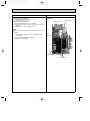
● MU-A12WA-
SPLIT-TYPE AIR CONDITIONERS
1
has been added.
Please void OB449.
OUTDOOR UNIT
SERVICE MANUAL
HFC
utilized
No. OB449
REVISED EDITION-A
R410A
Wireless type
Models
MU-A09WA
MU-A12WA
MU-A12WA-
1
Indoor unit service manual
MS-A•WA Series (OB448)
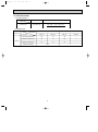
CONTENTS
MU-A09WA
1. TECHNICAL CHANGES ····································2
2. PART NAMES AND FUNCTIONS······················5
3. SPECIFICATION·················································6
4. OUTLINES AND DIMENSIONS ·························8
5. WIRING DIAGRAM ············································9
6. REFRIGERANT SYSTEM DIAGRAM ··············10
7. DATA·································································12
8. TROUBLESHOOTING······································16
9. DISASSEMBLY INSTRUCTIONS ····················17
10. PARTS LIST······················································22
10-1. PARTS LIST·············································22
10-2. RoHS PARTS LIST ··································24
MU-A12WA
NOTE:
This service manual describes technical data of the outdoor units.
RoHS compliant products have <G> mark on the spec name plate.
For servicing of RoHS compliant products, refer to the RoHS PARTS
LIST (RoHS compliant).
TM
OB449A.qxp
06.5.9 11:13 AM
Page 2
Revision : A
• MU-A12WA-
1
1
has been added.
TECHNICAL CHANGES
MU09TW ➔ MU-A09WA
MU12TN ➔ MU-A12WA
1.Outdoor unit model has been changed.
2.Refrigerant has been changed. (R22 ➔ R410A)
3.Compressor has been changed.
MUA12WA ➔
MU-A12WA-
1
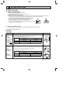
1.WIRING DIAGRAM has been changed.
INFORMATION FOR THE AIR CONDITIONER WITH R410A REFRIGERANT
oil
Refrigeration
Refrigerant
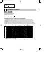
• This room air conditioner adopts HFC refrigerant (R410A) which never destroys the ozone layer.
• Pay particular attention to the following points, though the basic installation procedure is same as that for R22 air
conditioners.
1 As R410A has working pressure approximate 1.6 times as high as that of R22, some special tools and piping parts/
materials are required. Refer to the table below.
2 Take sufficient care not to allow water and other contaminations to enter the R410A refrigerant during storage and
installation, since it is more susceptible to contaminations than R22.
3 For refrigerant piping, use clean, pressure-proof parts/materials specifically designed for R410A. (Refer to 2. Refrigerant
piping.)
4 Composition change may occur in R410A since it is a mixed refrigerant. When charging, charge liquid refrigerant to prevent
composition change.
Refrigerant
Composition (Ratio)
Refrigerant handling
Chlorine
Safety group (ASHRAE)
Molecular weight
Boiling point (°F)
Steam pressure [77°F](PSIG)
Saturated steam density [77°F](lb/ft3)
Combustibility
ODP w1
GWP w2
Refrigerant charge method
Additional charge on leakage
Kind
Color
Smell
New refrigerant
R410A
HFC-32: HFC-125 (50%:50%)
Pseudo-azeotropic refrigerant
Not included
A1/A1
72.6
-60.5
225.82
3.995
Non combustible
0
1730
From liquid phase in cylinder
Possible
Incompatible oil
Non
Non
w1 :Ozone Destruction Parameter : based on CFC-11
w2 :Global Warmth Parameter
: based on CO2
2
Previous refrigerant
R22
R22 (100%)
Single refrigerant
Included
A1
86.5
-41.4
136.34
2.772
Non combustible
0.055
1700
Gas phase
Possible
Compatible oil
Light yellow
Non
06.5.9 11:13 AM
Page 3
New Specification
Current Specification
The incompatible refrigeration oil easily separates from
Since refrigerant and refrigeration oil are compatible each,
refrigerant and is in the upper layer inside the suction muffler. refrigeration oil goes back to the compressor through the
Raising position of the oil back hole enables to back the
lower position oil back hole.
refrigeration oil of the upper layer to flow back to the
compressor.
Suction muffler
Suction muffler
Oil back hole
Compressor
Compressor
refrigeration oil
Oil back hole
Refrigerant
refrigeration oil /Refrigerant
Conversion chart of refrigerant temperature and pressure
580
508
R410A
435
R22
363
(PSIG)
Saturated liquid pressure
Compressor
OB449A.qxp
290
218
145
73
0
-73
-22
-4
14
32
50
68
86
104 122 140 (°F)
3
OB449A.qxp
06.5.9 11:13 AM
Page 4
1.Tools dedicated for the air conditioner with R410A refrigerant
The following tools are required for R410A refrigerant. Some R22 tools can be substituted for R410A tools.
R410A tools
Description
Can R22 tools be used?
Gauge manifold
No
R410A has high pressures beyond the measurement range of existing
gauges.
Charge hose
No
Hose material have been changed to improve the pressure resistance.
No
Dedicated for HFC refrigerant.
Yes
1/4in. and 3/8in.
Gas leak detector
Torque wrench
No
1/2in. and 5/8in.
Flare tool
Yes
Clamp bar hole has been enlarged to reinforce the spring strength in the tool.
Flare gauge
Vacuum pump
adapter
Electronic scale for
refrigerant charging
New
Provided for flaring work (to be used with R22 flare tool).
Provided to prevent the back flow of oil. This adapter enables you to use
vacuum pumps.
It is difficult to measure R410A with a charging cylinder because the
refrigerant bubbles due to high pressure and high-speed vaporization
New
New
No : Not Substitutable for R410A
Yes : Substitutable for R410A
2.Refrigerant piping
1 Specifications
Use the copper or copper-alloy seamless pipes for refrigerant that meet the following specifications.
Outside diameter(in) Wall thickness (in)
Insulation material
1/4
0.0315
3/8
0.0315
Heat resisting foam plastic
1/2
0.0315
Specific gravity 0.045 Thickness 0.315 in
5/8
0.0394
2 Flaring work and flare nut
Flaring work for R410A pipe differs from that for R22 pipe.
For details of flaring work, refer to Installation manual “FLARING WORK”.
Pipe diameter
Dimension of flare nut
mm(in.)
inch
R410A
R22
1/4
17 (11/16)
17 (11/16)
3/8
22 (7/8)
22 (7/8)
1/2
26 (1-1/32)
24 (15/16)
5/8
29 (1-5/32)
27 (1-1/16)
4
OB449A.qxp
06.5.9 11:13 AM
Page 5
3.Refrigerant oil
Apply the special refrigeration oil (accessories: packed with indoor unit) to the flare and the union seat surfaces.
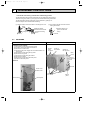
4.Air purge
• Do not discharge the refrigerant into the atmosphere.
Take care not to discharge refrigerant into the atmosphere during installation, reinstallation, or repairs to the refrigerant
circuit.
• Use the vacuum pump for air purging for the purpose of environmental protection.
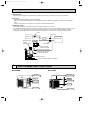
5.Additional charge
For additional charging, charge the refrigerant from liquid phase of the gas cylinder.
If the refrigerant is charged from the gas phase, composition change may occur in the refrigerant inside the cylinder and the
outdoor unit. In this case, ability of the refrigeration cycle decreases or normal operation can be impossible. However,
charging the liquid refrigerant all at once may cause the compressor to be locked. Thus, charge the refrigerant slowly.
Union
Stop valve
Indoor unit
Liquid pipe
Outdoor unit
Gas pipe
Refrigerant gas
cylinder
operating valve
Service port
Gauge manifold
valve (for R410A)
Charge hose (for R410A)
Refrigerant gas cylinder
for R410A with siphon
Refrigerant (liquid)
Electronic scale for refrigerant charging
2
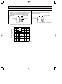
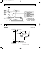
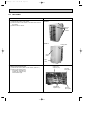
PART NAMES AND FUNCTIONS
MU-A09WA
MU-A12WA
Air inlet
(back and side)
Air inlet
(back and side)
Piping
Piping
Drain hose
Drain hose
Air outlet
Air outlet
Drain outlet
Drain outlet
5
OB449A.qxp
3
06.5.9 11:13 AM
Page 6
SPECIFICATION
Model
Item
Capacity
❈1
Btu/h
Cooling
Rated(Minimum~Maximum)
Power consumption
W
Cooling ❈1
Rated(Minimum~Maximum)
❈1
❈2
EER
[SEER]
Cooling
OUTDOOR UNIT MODEL
External finish
Power supply
V, phase, Hz
Max. fuse size (time delay)
A
A
Min. circuit ampacity
F.L.A
Fan motor
Model
Winding resistance (at 68˚F) Ω
Compressor
R.L.A
L.R.A
Refrigerant control
dB(A)
Sound level
in.
W
in.
Dimensions
D
in.
H
Ib.
Weight
REMOTE CONTROLLER
REFRIGERANT PIPING
in.
Refrigerant pipe size
Liquid
in.
(Min. wall thickness)
Gas
Indoor
Connection method
Outdoor
ft.
Height difference
Between the indoor
ft.
Piping length
& outdoor units
Refrigerant charge (R410A)
cc
Refrigerating oil (Model)
MS-A09WA
MS-A12WA
9,500
12,000
870
1,070
10.9 [13.0]
MU-A09WA
11.2 [13.0]
MU-A12WA
Munsell 3Y 7.8/1.1
115, 1, 60
20
15
16
14
0.926
0.63
RN110WHDHT
RN092WHDHT
C-R 0.66
C-S 1.23
C-R 0.81
C-S 1.49
10.82
9.30
56
47
Capillary tube
52
47
33-7/16
31-1/2
11-7/16
11-1/4
23-13/16
21-5/8
96
78
Wireless type
Not supplied
1/4 (0.0315)
1/2 (0.0315)
3/8 (0.0315)
Flared
Flared
35
65
3lb. 1oz.
2lb.5oz.
350 (NE022)
NOTE : Test conditions are based on ARI 210/240.
❈1 : Rating conditions (cooling) — Indoor : 80˚FDB, 67˚FWB, Outdoor : 95˚FDB, (75˚FWB)
6
OB449A.qxp
06.5.9 11:13 AM
Page 7
(Unit : [˚F])
❈2
Mode
ARI
Test
Indoor air condition
Outdoor air condition
Dry bulb
Wet bulb
Dry bulb
Wet bulb
SEER "A" Cooling Steady State
(Cooling) at rated compressor Speed
80
67
95
(75)
"B-2" Cooling Steady State
at rated compressor Speed
80
67
82
(65)
"B-1" Cooling Steady State
at minimum compressor Speed
80
67
82
(65)
Low ambient Cooling Steady State
at minimum compressor Speed
80
67
67
(53.5)
Intermediate Cooling Steady State
At Intermediate compressor Speed
80
67
87
(69)
Operating Range
Cooling
Maximum
Minimum
Indoor intake air temperature Outdoor intake air temperature
115˚FDB
95˚FDB, 71˚FWB
67˚FDB
67˚FDB, 57˚FWB
7
OB449A.qxp
06.5.9 11:13 AM
4
Page 8
OUTLINES AND DIMENSIONS
Unit : inch
MU-A09WA
REQUIRED SPACE
1-3/4
15-3/4
Drainage hole
1-5/8
13-9/16
11/16
12 ~ 12-3/4
Air in
Air in
. or
4 in
4 in
. or
re
14
.
8 in
2- 3/8o13/16 Oval hole
29/32
7/8
11-1/4
17/32
in.
or m
ore
5-7/8
2
11-1/32
Liquid pipe : 1/4 (flared)
Gas pipe : 3/8 (flared)
13/32
11-29/32
6-23/32
19-11/16
5-15/16
31-1/2
2-23/32
MU-A12WA
4 in. or more
Drainage
hole [5/8
REQUIRED SPACE
13-31/32
13/16
13-3/4
. or
4 in
e
mor
Air in
4 in
Air out
13-9/16
11-7/16
Air in
Drainage
3holes [1-5/16
12-3/16
. or
3-17/32
1-3/8
ore
or m
Open two sides of left,
right, or rear side.
handle
21-5/8
e
mor
mo
1-9/16
Air out
mo
re
1-15/16
re
r mo
.o
0 in
2
1-3/16
Service panel
Liquid refrigerant
pipe joint
23-13/16
7-3/16
3-3/16
3-15/16
6-3/16
19-11/16
33-7/16
2-1/4
8
6-5/16
35
11-1/2
30
Refrigerant pipe
(flared) [1/4
13/16
9-3/4
Basically open 4inch or more
without any obstruction in front
and on both sides of the unit.
Gas refrigerant
pipe joint
Rfrigerant pipe
(flared) [1/2
14
in.
or m
ore
OB449A.qxp
06.5.9 11:13 AM
5
Page 9
WIRING DIAGRAM
MU-A09WA
MU-A12WA
9
OB449A.qxp
06.5.9 11:14 AM
MU-A12WA-
6
Page 10
1
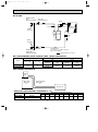
REFRIGERANT SYSTEM DIAGRAM
MU-A09WA
Unit : inch (mm)
Refrigerant pipe
{3/8
(with heat insulator)
Stop valve
(with service port)
Muffler
Flared
connection
Service port
Service port
Compressor
Outdoor
heat
exchanger
Strainer
#100
Flared
connection
Stop valve Capillary tube
O.D. 0.118 x I.D. 0.055 x 21-21/32
Refrigerant pipe
({3.0 x {1.4 x 550)
(Option){1/4
(with heat insulator)
Refrigerant flow in cooling
10
OB449A.qxp
06.5.9 11:14 AM
Page 11
MU-A12WA
Refrigerant pipe
Stop valve
{1/2
(with heat insulator) (with service port)
Muffler
Service port
Outdoor heat
exchanger
Service port
Flared
connection
Strainer
#100
Compressor
Flared
connection
Stop valve
Capillary tube
O.D. 0.118 x I.D. 0.063 x 27-9/16
({3.0 x {1.6 x 700)
Refrigerant pipe
(Option){1/4
(with heat insulator)
Refrigerant flow in cooling
MAX. REFRIGERANT PIPING LENGTH & MAX. HEIGHT DIFFERENCE
Refrigerant piping : ft
Model
MU-A09WA
MU-A12WA
Piping size : in.
Additional piping Additional piping
Max. length
Max. length
A
B
65
35
Gas
Liquid
Outside
diameter
Minimum
Wall
thickness
Outside
diameter
Minimum
Wall
thickness
[ 3/8
[ 1/2
0.0315
[ 1/4
0.0315
MAX. HEIGHT DIFFERENCE
Indoor
unit
Max. Height
difference
B
Additional Piping
Max. length
A
Outdoor unit
ADDITIONAL REFRIGERANT CHARGE(R410 : oz.)
Model
Outdoor unit precharged
MU-A09WA
MU-A12WA
2lb. 5oz.
3lb. 1oz.
25ft
30ft
Refrigerant piping length (one way)
40ft
45ft
50ft
55ft
35ft
60ft
65ft
0
1.08
2.16
7.56
8.64
3.24
4.32
5.40
6.48
NOTE : Calculation : Xoz.=1.08/5oz./ft ✕ (Refrigerant piping length (ft)-25)
11
OB449A.qxp
06.5.9 11:14 AM
7
Page 12
DATA
MS-A09WA MS-A12WA
7-1. PERFORMANCE DATA
1) COOLING CAPACITY
Outdoor intake air DB temperature (˚F)
Indoor air
Model
MS-A09WA
MS-A12WA
75
85
95
105
115
IWB
(˚F)
TC
SHC
TPC
TC
SHC
TPC
TC
SHC
TPC
TC
SHC
TPC
TC
SHC
TPC
71
11.6
6.4
0.77
10.9
5.9
0.85
10.2
5.6
0.91
9.5
5.2
0.96
8.7
4.8
1.00
67
11.0
7.5
0.73
10.3
7.0
0.80
9.5
6.5
0.87
8.8
6.0
0.92
8.1
5.5
0.97
63
10.4
8.4
0.70
9.6
7.8
0.77
8.9
7.3
0.83
8.1
6.6
0.89
7.4
6.0
0.92
71
14.7
8.3
0.95
13.7
7.8
1.04
12.9
7.3
1.12
12.0
6.8
1.18
11.0
6.3
1.23
67
13.9
9.7
0.90
13.0
9.1
0.99
12.0
8.4
1.07
11.2
7.8
1.13
10.3
7.2
1.19
63
13.1
10.9
0.86
12.1
10.1
0.95
11.3
9.4
1.02
10.3
8.6
1.09
9.4
7.8
1.13
Notes 1. I WB : Intake air wet-bulb temperature.
TC : Total Capacity (x103 Btu/h), SHC : Sensible Heat Capacity (x103 Btu/h)
TPC : Total Power Consumption (kW)
2. SHC is based on 80˚F of indoor intake air DB temperature.
2) COOLING CAPACITY CORRECTIONS
Refrigerant piping length (one way)
Model
25ft (std)
40ft
65ft
1.0
0.954
0.878
MS-A09WA
MS-A12WA
7-2. PERFORMANCE CURVE
NOTE : A point on the curve shows the reference point.
MS-A09WA
MS-A12WA
Cooling
SHF at rating condition = 0.68
Airflow = 300CFM
10
Total capacity ( o10 Btu/h)
Indo
or in
take
air
12
16
WB
temp
eratu
re (°
F)
71
67
63
8
6
1.1
1.0
0.9
0.8
(°F)
rature
tempe
B
W
e air
r intak
Indoo
Total power consumption (kW)
Total power consumption (kW)
Total capacity ( o10 Btu/h)
14
71
67
63
0.7
0.6
67
75
Cooling
SHF at rating condition = 0.70
Airflow = 363CFM
85
95
105
Outdoor intake air DB temperature (°F)
Indo
12
take
air W
B te
12
mpe
ratu
re (°
F)
71
67
10
63
8
1.3
1.2
1.1
B
e air W
r intak
Indoo
(°F)
rature
tempe
71
67
63
1.0
0.9
0.8
67
115
or in
14
75
85
95
105
Outdoor intake air DB temperature (°F)
115
06.5.9 11:14 AM
Page 13
7-3. Condensing pressure
Data is based on the condition of indoor humidity 50%.
Air flow should be set at High.
A point on the curve shows the reference point.
MU-A09WA
(PSIG)
460
440
86
80
75
70
400
200
)
°F
e(
380
(PSIG)
r
atu
180
r
360
r
oo
DB
te
e
mp
Suction pressure
Condensing pressure
420
Ind
340
320
160
Indoor DB te
mperature (°F
)
86
80
140
75
300
70
120
280
260
68 70
75
80
85
90
95
100
100
68 70
105( F)
75
80
85
90
95
100
105( F)
Outdoor ambient temperature
Outdoor ambient temperature
MU-A12WA
(PSIG)
460
440
86
80
75
70
420
400
200
)
°F
e(
tur
ra
380
(PSIG)
180
e
360
or
do
DB
p
tem
Suction pressure
Condensing pressure
OB449A.qxp
In
340
320
Indoor DB te
mperature (°F
)
86
160
80
75
140
70
300
120
280
260
68 70
75
80
85
90
95
100
105( F)
100
68 70
75
80
85
90
95
Outdoor ambient temperature
Outdoor ambient temperature
13
100
105( F)
OB449A.qxp
06.5.9 11:14 AM
Page 14
7-4. STANDARD OPERATION DATA
Model
MS-A09WA
MS-A12WA
Unit
Cooling
Cooling
Btu / h
9500
12000
SHF
—
0.68
0.70
Input
kW
0.87
1.07
MS-A09WA
MS-A12WA
Item
Capacity
Total
INDOOR UNIT MODEL
115, 1, 60
115, 1, 60
kW
0.019
0.035
A
0.27
0.51
MU-A09WA
MU-A12WA
115, 1, 60
115, 1, 60
Power supply (V, phase, Hz)
Input
Fan motor current
Electrical
circuit
OUTDOOR UNIT MODEL
Power supply (V, phase, Hz)
kW
0.851
1.035
Comp. current
A
6.74
7.96
Fan motor current
A
0.63
0.93
Condensing pressure
PSIG
372
375
Suction pressure
PSIG
144
150
Discharge temperature
˚F
154
149
Condensing temperature
˚F
110
111
˚F
48
50
Comp. shell bottom temp
˚F
146
139
Ref. pipe length
ft.
25
25
Refrigerant charge (R22)
—
2Ib. 5oz.
3Ib. 1oz.
Input
Refrigerant
circuit
Suction temperature
DB
˚F
80
80
WB
˚F
67
67
DB
˚F
57
59
WB
˚F
56
58
rpm
1160
1220
Intake air temperature
Indoor
unit
Discharge air temperature
Fan speed (High)
CFM
300 (Wet)
363 (Wet)
DB
˚F
95
95
WB
˚F
—
—
Fan speed
rpm
830
830
Airflow
CFM
1083
1327
Airflow (High)
Intake air temperature
Outdoor
unit
14
OB449A.qxp
06.5.9 11:14 AM
Page 15
7-5. OPERATING RANGE
(1) POWER SUPPLY
Rating
Outdoor unit
Guaranteed Voltage
Min. 103V
115V 60Hz 1[
115V Max. 127V
(2) OPERATION
Function
Intake air
temperature
Outdoor
Indoor
DB (˚F)
WB (˚F)
DB (˚F)
WB (˚F)
Standard temperature
80
67
95
—
Maximum temperature
95
71
115
—
Minimum temperature
67
57
67
—
Condition
Cooling
Maximum humidity
78%
15
—
OB449A.qxp
8
06.5.9 11:14 AM
Page 16
TROUBLESHOOTING
MU-A09WA MU-A12WA
8-1. Cautions on troubleshooting
1. Before troubleshooting, check the following:
1) Check the power supply voltage.
2) Check the indoor/outdoor connecting wire for mis-wiring.
2. Take care the following during servicing.
1).Before servicing the air conditioner, be sure to turn OFF the main unit first with the remote controller, and then after
confirming the horizontal vane is closed, turn OFF the breaker and / or disconnect the power plug.
2) Be sure to turn OFF the power supply before removing the front panel,
the cabinet, the top panel and the electronic control P.C. board.
3) When removing the electronic control P.C. board, hold the edge of the
board with care NOT to apply stress on the components.
4) When connecting or disconnecting the connectors, hold the housing of the
connector. DO NOT pull the lead wires.
Lead wiring
Housing point
8-2. Instruction of trouble shooting
If indoor unit and outdoor unit doesn’t operate, please check of outdoor unit fuse F.
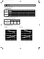
8-3.Trouble criterion of main parts
MU-A09WA
MU-A12WA
Check method and criterion
Part name
Figure
Compressor (MC)
INNER
PROTECTOR
MU-A09WA
302 i 9°F OPEN
194 i18°F CLOSE
MU-A12WA
338 i 9°F OPEN
194 i18°F CLOSE
MU-A12WA- 1
311i 9°F OPEN
194 i18°F CLOSE
Measure the resistance between the terminals with a tester.
(Coil wiring temperature 14°F ~ 104°F)
WHT
C
Normal
P
Color of the
lead wire
MU-A09WA
MU-A12WA
C-R
0.71~0.87"
0.58~0.71"
C-S
1.31~1.61"
1.09~1.33"
Outdoor fan
motor (MF)
S
R BLK
RED
MU-A09WA
MAIN
INNER
PROTECTOR
MU-A09WA
248 i 9°F OPEN
INNER
PROTECTOR
MU-A12WA
248 i 9°F OPEN
Measure the resistance between the terminals with a tester.
(Coil wiring temperature 14°F ~ 104°F)
Normal
Color of the
lead wire
MU-A09WA
MU-A12WA
WHT-BLK
51~63"
27~33"
BLK-RED
62~76"
34~41"
AUX.
Fuse
BLK
RED WHT
MU-A12WA
MAIN
AUX.
BLK
RED ORN WHT
P:INNER PROTECTOR
16
OB449A.qxp
06.5.9 11:14 AM
9
Page 17
DISASSEMBLY INSTRUCTIONS
<"Terminal with locking mechanism" Detaching points>
The terminal which has the locking mechanism can be detached as shown below.
There are two types ( Refer to (1) and (2)) of the terminal with locking mechanism.
The terminal without locking mechanism can be detached by pulling it out.
Check the shape of the terminal before detaching.
(1) Slide the sleeve and check if there is a locking lever or not.
(2) The terminal with this connector has the
locking mechanism.
Sleeve
Locking lever
1Slide the sleeve.
2Pull the terminal while
pushing the locking
lever.
1Hold the sleeve, and
pull out the terminal
slowly.
Connector
9-1. MU-A09WA
PHOTOS
OPERATING PROCEDURE
Photo 1
1. Removing the cabinet.
(1)
(2)
(3)
(4)
Remove the screw fixing the service panel.
Pull down the service panel and remove it.
Remove the conduit cover.
Disconnect the power supply wire and indoor/outdoor connecting wire.
(5) Remove the screws fixing the top panel.
(6) Remove the top panel.
(7) Remove the screws fixing the cabinet.
(8) Remove the cabinet.
(9) Remove the screws fixing the back panel.
(10) Remove the back panel.
Screws
of the
top panel
Screw of
the cabinet
Screws of
the top panel
Back
panel
Screw of
the service
panel
Photo 2
Hooks
Screw of the
conduit cover
Screws of
the cabinet
Conduit cover
Conduit plate
17
Service
panel
OB449A.qxp
06.5.9 11:14 AM
Page 18
OPERATING PROCEDURE
PHOTOS
2. Removing the electrical parts
(1) Remove the service panel and the cabinet.(Refer to 1.)
(2) Remove the following parts.
•Compressor capacitor (C1)
•Outdoor fan capacitor (C2)
•Terminal block (TB1,TB2)
•Surge absorber (DSAR)
•Compressor contactor (52C)
Photo 3
Compressor capacitor (C1)
Compressor contactor (52C)
Terminal
block
(TB1)
Outdoor fan
capacitor (C2)
Terminal block (TB2)
Surge absorber (DSAR)
3. Removing the propeller and the outdoor fan motor
(1) Remove the cabinet. (Refer to 1.)
(2) Remove the propeller nut and the propeller.
NOTE : Loose the propeller in the rotating direction for
removal.
When attaching the propeller, align the mark on the
propeller and the motor shaft cut section.
Set the propeller in position by using the cut on the shaft
and the mark on the propeller.
(3) Remove the lead clamps and outdoor fan motor lead wires.
(4) Remove the screws fixing the outdoor fan motor.
(5) Remove the outdoor fan motor.
Photo 4
Outdoor fan motor
connector
Propeller
Screws of the
outdoor fan motor
Conduit
plate
Sound proof felt
18
OB449A.qxp
06.5.9 11:14 AM
Page 19
OPERATING PROCEDURE
PHOTOS
4. Removing the compressor
(1) Remove the cabinet. (Refer to 1.)
(2) Remove the relay panel.
(3) Remove the soundproof felt.
(4) Remove the terminal cover on compressor.
(5) Disconnect lead wires from the glass terminal of the compressor.
(6) Recover gas from the refrigerant circuit.
Photo 5
Suction pipe
Discharge pipe
NOTE
● Recover gas from the pipes until the pressure gauge shows
0 PSIG.
(7) Disconnect the welded part of the suction pipe and discharge pipe.
(8) Remove the nuts fixing the compressor.
(9) Remove the compressor.
Glass
terminal
Compressor
Compressor nuts
19
OB449A.qxp
9-2.
06.5.9 11:14 AM
Page 20
MU-A12WA
OPERATING PROCEDURE
PHOTOS
1. Removing the cabinet
(1) Remove the screws of the cabinet.
(2) Hold the bottom of the cabinet on the both side to remove
the cabinet.
(3) Remove the the cabinet.
Photo 1
Screws
of the
cabinet
Photo 2
Conduit plate
Service
panel
Valve
cover
2. Removing the electrical parts
(1) Remove the service panel and the cabinet. (Refer to 1.)
(2) Remove the following parts.
•Compressor capacitor (C1)
•Outdoor fan capacitor (C2)
•Terminal block (TB)
Photo 3
Outdoor fan
capacitor (C2)
Compressor
capacitor (C1)
20
Terminal
block (TB1)
Terminal
block (TB2)
OB449A.qxp
06.5.9 11:14 AM
Page 21
OPERATING PROCEDURE
PHOTOS
3. Removing propeller and the outdoor fan motor
(1) Remove the cabinet. (Refer to 1)
(2) Remove the propeller nut and remove the propeller.
NOTE : Loose the propeller in the rotating direction for
removal.
When attaching the propeller, align the mark on the
propeller and the motor shaft cut section.
Set the propeller in position by using the cut on the
shaft and the mark on the propeller.
(3) Disconnect the connector and remove the lead clamps and
outdoor fan motor lead wires.
(4) Remove the screws fixing the outdoor fan motor.
(5) Remove the outdoor fan motor.
Photo 4
Hook
Propeller
4. Removing the compressor
(1) Remove the cabinet. (Refer to 1)
(2) Remove the relay panel.
(3) Remove the soundproof felt.
(4) Remove the terminal cover.
(5) Pull out the lead wires from the glass terminal of the compressor.
(6) Recover gas from the refrigerant circuit.
(7) Disconnect the welded part of the suction pipe and discharge pipe.
(8) Remove the nuts fixing the compressor and the compressor.
Lead clamp
Connector
Soundproof felt
Propeller nut
Photo 5
Discharge
pipe
Relay
panel
Glass
terminal
NOTE
● Before using a burner, reclaim gas from the pipes until the
pressure gauge shows 0 PSIG.
● Use the burner under the condition that gas can be recovered
even when the inner pressure rises by heat.
Suction
pipe
Compressor
Compressor set nuts
21
OB449A.qxp
06.5.9 11:14 AM
10
Page 22
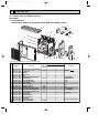
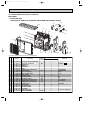
PARTS LIST
10-1. PARTS LIST (non-RoHS compliant)
MU-A09WA
1. OUTDOOR UNIT
STRUCTURAL PARTS, ELECTRICAL PARTS AND FUNCTIONAL PARTS
17
16
22
15
21
20
14
19
1
13
2
18
3
4
6
5
7
8
10
9
12
11
Part number that is circled is not shown in the illustration.
No.
1
2
3
4
5
6
7
8
9
10
11
12
13
14
15
16
17
18
19
20
21
22
23
24
Part No.
E02
E02
E02
E02
E02
E02
E02
E02
E02
E02
E02
E02
E02
E02
E02
E02
E02
E02
E02
E02
E02
E02
E02
E02
A49
A49
665
903
927
905
075
A49
A49
A49
A54
A49
A50
A49
A49
545
A49
A49
900
929
900
927
441
282
630
301
501
232
521
290
506
900
661
662
233
245
374
374
350
353
340
641
293
523
515
297
936
383
Part name
OUTDOOR HEAT EXCHANGER
OUTDOOR FAN MOTOR
PROPELLER
CABINET
GRILLE(OUT)
BASE
COMPRESSOR RUBBER SET
COMPRESSOR
STOP VALVE(GAS)
STOP VALVE(LIQUID)
BACK PANEL
SERVICE PANEL
TERMINAL BLOCK
TERMINAL BLOCK
OUTDOOR FAN CAPACITOR
COMPRESSOR CAPACITOR
COMPRESSOR CONTACTOR
SERVICE PORT
SEPARATOR
CONDENSER NET
MOTOR SUPPORT
TOP PANEL
CAPILLARY TUBE
SURGE ABSORBER
Symbol
in Wiring
Diagram
MF
MC
TB1
TB2
C2
C1
52C
DSAR
22
Q'ty/unit
MU-A09WA
1
1
1
1
1
1
3
1
1
1
1
1
1
1
1
1
1
2
1
1
1
1
1
1
Remarks
RA6W26-
3RUBBERS/SET
RN092WHDHT
{3/8
{1/4
3P
2P
7.0µF/250VAC
70µF/220VAC
1PCE/SET
O.D. 0.118 x I.D. 0.055x21-21/32
OB449A.qxp
06.5.9 11:14 AM
Page 23
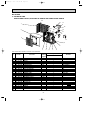
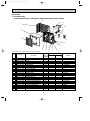
MU-A12WA
2. OUTDOOR UNIT
STRUCTURAL PARTS, ELECTRICAL PARTS AND FUNCTIONAL PARTS
22
18
17
1
16
21
2
20
15
14
19
13
12
3
11
10
9
4
5
6
8
7
Part number that is circled is not shown in the illustration.
No.
Part No.
1 E02 A50
2 E02 817
3 E02 817
4 E02 141
5 E02 139
6 E02 A50
7 E02 075
8 E02 A27
9 E02 A50
10 E02 A50
11 E02 819
12 E02 A49
13 E02 A50
14 E02 A49
15 E02 A50
16 E02 A50
17 E02 A49
18 E02 A50
19 E02 A50
20 E02 A50
21 E02 A50
22 E02 817
23 E02 134
24 E02 890
233
232
521
501
515
900
506
290
661
662
650
641
245
374
374
353
340
350
293
630
301
009
936
383
Part name
BACK PANEL
CABINET
GRILLE
PROPELLER
MOTOR SUPPORT
COMPRESSOR
COMPRESSOR RUBBER SET
BASE
STOP VALVE(GAS)
STOP VALVE(LIQUID)
VALVE COVER
SERVICE PORT
SERVICE PANEL
TERMINAL BLOCK
TERMINAL BLOCK
COMPRESSOR CAPACITOR
COMPRESSOR CONTACTOR
OUTDOOR FAN CAPACITOR
SEPARATOR
OUTDOOR HEAT EXCHANGER
OUTDOOR FAN MOTOR
HANDLE
CAPILLARY TUBE
SURGE ABSORBER
Symbol
in Wiring
Diagram
MC
TB2
TB1
C1
52C
C2
MF
23
Q'ty/unit
Remarks
MU-A12WA
1
1
1
1
1
1
3
1
1
1
1
2
1
1
1
1
1
1
1
1
1
1
1
1
RN110WHDHT
3RUBBERS/SET
{1/2
{1/4
1PCE / SET
2P
3P
75+/220V AC
9.5+/250V AC
RA6W50O.D. 0.118 ✕ I.D. 0.063 ✕ 27-9/16
OB449A.qxp
06.5.9 11:14 AM
Page 24
10-2. RoHS PARTS LIST (RoHS compliant)
MU-A09WA
1. OUTDOOR UNIT
STRUCTURAL PARTS, ELECTRICAL PARTS AND FUNCTIONAL PARTS
16
17
22
15
21
20
14
19
1
13
2
18
3
4
6
5
7
8
9
10
12
11
No.
RoHS
Part number that is circled is not shown in the illustration.
1
2
3
4
5
6
7
8
9
10
11
12
13
14
15
16
17
18
19
20
21
22
23
24
G
G
G
G
G
G
G
G
G
G
G
G
G
G
G
G
G
G
G
G
G
G
G
G
Part No.
E12
E12
E12
E12
E12
E12
E12
E12
E12
E12
E12
E12
E12
E12
E12
E12
E12
E12
E12
E12
E12
E12
E12
E12
A49
A49
665
903
927
905
075
A49
A49
A49
A54
A49
A50
A49
A49
545
A49
A49
900
929
900
927
441
282
630
301
501
232
521
290
506
900
661
662
233
245
374
374
350
353
340
641
293
523
515
297
936
383
Part name
OUTDOOR HEAT EXCHANGER
OUTDOOR FAN MOTOR
PROPELLER
CABINET
GRILLE(OUT)
BASE
COMPRESSOR RUBBER SET
COMPRESSOR
STOP VALVE(GAS)
STOP VALVE(LIQUID)
BACK PANEL
SERVICE PANEL
TERMINAL BLOCK
TERMINAL BLOCK
OUTDOOR FAN CAPACITOR
COMPRESSOR CAPACITOR
COMPRESSOR CONTACTOR
SERVICE PORT
SEPARATOR
CONDENSER NET
MOTOR SUPPORT
TOP PANEL
CAPILLARY TUBE
SURGE ABSORBER
Symbol
in Wiring
Diagram
MF
MC
TB1
TB2
C2
C1
52C
DSAR
24
Q'ty/unit
MU-A09WA
1
1
1
1
1
1
3
1
1
1
1
1
1
1
1
1
1
2
1
1
1
1
1
1
Remarks
RA6W26-
3RUBBERS/SET
RN092WHDHT
{3/8
{1/4
3P
2P
7.0µF/250VAC
70µF/220VAC
1PCE/SET
O.D. 0.118 x I.D. 0.055x21-21/32
06.5.9 11:14 AM
Page 25
MU-A12WA
2. OUTDOOR UNIT
STRUCTURAL PARTS, ELECTRICAL PARTS AND FUNCTIONAL PARTS
22
18
17
1
16
21
2
20
15
14
19
13
12
3
11
10
9
4
5
6
7
8
Part number that is circled is not shown in the illustration.
No.
RoHS
OB449A.qxp
1
2
3
4
5
6
7
8
9
10
11
12
13
14
15
16
17
18
19
20
21
22
23
24
G
G
G
G
G
G
G
G
G
G
G
G
G
G
G
G
G
G
G
G
G
G
G
G
Part No.
E12
E12
E12
E12
E12
E12
E12
E12
E12
E12
E12
E12
E12
E12
E12
E12
E12
E12
E12
E12
E12
E12
E12
E12
A50
817
817
141
139
A50
075
A27
A50
A50
819
A49
A50
A49
A50
A50
A49
A50
A50
A50
A50
817
134
890
233
232
521
501
515
900
506
290
661
662
650
641
245
374
374
353
340
350
293
630
301
009
936
383
Part name
Q'ty/unit
Symbol
in Wiring
MU-A12WA MU-A12WA- 1
Diagram
BACK PANEL
CABINET
GRILLE
PROPELLER
MOTOR SUPPORT
COMPRESSOR
COMPRESSOR RUBBER SET
BASE
STOP VALVE(GAS)
STOP VALVE(LIQUID)
VALVE COVER
SERVICE PORT
SERVICE PANEL
TERMINAL BLOCK
TERMINAL BLOCK
COMPRESSOR CAPACITOR
COMPRESSOR CONTACTOR
OUTDOOR FAN CAPACITOR
SEPARATOR
OUTDOOR HEAT EXCHANGER
OUTDOOR FAN MOTOR
HANDLE
CAPILLARY TUBE
SURGE ABSORBER
MC
TB2
TB1
C1
52C
C2
MF
25
1
1
1
1
1
1
3
1
1
1
1
2
1
1
1
1
1
1
1
1
1
1
1
1
1
1
1
1
1
1
3
1
1
1
1
2
1
1
1
1
1
1
1
1
1
1
1
1
Remarks
RN110WHDHT
3RUBBERS/SET
{1/2
{1/4
1PCE / SET
2P
3P
75+/220V AC
9.5+/250V AC
RA6W50O.D. 0.118 ✕ I.D. 0.063 ✕27-9/26
OB449A.qxp
06.5.9 11:14 AM
Page 26
26
OB449A.qxp
06.5.9 11:14 AM
Page 27
27
OB449A.qxp
06.5.9 11:14 AM
Page 28
TM
C Copyright 2006 MITSUBISHI ELECTRIC ENGINEERING CO.,LTD.
Distributed in May 2006. No.OB449 REVISED EDITION-A 7
Distributed in Mar. 2006. No.OB449 7
New publication, effective May 2006
Specifications subject to change without notice.
3400 Lawrenceville Suwanee Road ● Suwanee, Georgia 30024
Toll Free: 800-433-4822 ● Toll Free Fax: 800-889-9904
www.mrslim.com
Specifications are subject to change without notice.