1
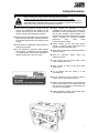
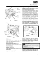
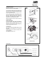
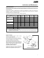
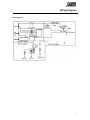
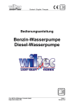
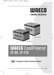
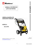
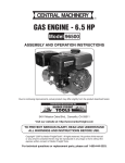
Operator’s Manual
MANLBA-105 REV A 14/12/05
Selecta Power
Petrol Generator Set
SILVAN AUSTRALIA PTY. LTD.
ABN 48 099 851 144
VICTORIA (HEAD OFFICE)
QUEENSLAND
WESTERN AUSTRALIA
89 Lewis Rd, Wantirna South, 3152
44 Lysaght St, Acacia Ridge, 4122
Telephone: (03) 9887 2788
Telephone: (07) 3345 9500
12 Cressall Rd, Balcatta
Telephone: (08) 6241 0900
Facsimile: (03) 9887 1035
Facsimile: (07) 3343 9511
Facsimile: (09) 9240 1832
Spare Parts Facsimile: (03) 9887 1637
www.silvanaust.com
1
New Product Warranty
WARRANTY POLICY
Silvan Australia Pty. Ltd. Warrants to its authorised dealer, who in turn warrants to the
original purchaser (owner) of each new Silvan product, that it will repair or replace,
without charge for labour or parts, any defective or malfunctioning parts in accordance
with the warranty limitations and adjustments schedule below.
PRODUCT – ALL
PRIVATE DOMESTIC USE – 12 MONTHS
PRIVATE and COMMERCIAL AGRICULTURAL USE – 12 MONTHS
AGRICULTURAL CONTRACTORS – 6 MONTHS
GOVERNMENT and MUNICIPAL DEPARTMENTS – 6 MONTHS
ALL OTHER NON-AGRICULTURAL APPLICATIONS – 3 MONTHS
HIRE COMPANIES – 3 MONTHS
The warranty period will begin on the date the product is delivered to the first retail
purchaser.
THIS WARRANTY COVERS:
• Claims resulting from defects in workmanship or material under normal use and service.
THIS WARRANTY DOES NOT COVER:
• Conditions resulting from misuse, negligence, alteration, accidental damage or failure to
perform normal maintenance services;
• Any product which has been repaired by other than an authorised Silvan Australia Pty.
Ltd. Service outlet so as, in any way in the sole and absolute judgement of Silvan
Australia Pty. Ltd., to affect adversely its performance and reliability;
• The replacement of wear and tear items such as diaphragms, V belts and ground
engaging components;
• Loss of time, inconvenience, loss of use of the product or any other consequential
damages.
The repair of defective products qualifying under this warranty will be performed by an
authorised Silvan Australia Pty. Ltd. Service outlet within a reasonable time following the
delivery of the product, at the cost of the owner, to the service outlet’s place of business.
The product will be repaired or replaced, using new parts sold by Silvan Australia Pty.
Ltd.
The owner is responsible for the performance of regular maintenance services as
specified in the Operator’s Manual applicable to the product.
• THIS WARRANTY IS THE ONLY WARRANTY APPLICABLE TO SILVAN
AUSTRALIA PTY. LTD. NEW PRODUCTS AND, TO THE MAXIMUM EXTENT
PERMITTED BY LAW, IS EXPRESSLY IN LIEU OF ANY OTHER WARRANTIES
EXPRESSED OR IMPLIED, INCLUDING ANY IMPLIED WARRANTY OF
MERCHANTABILITY OR FITNESS FOR A PARTICULAR PURPOSE.
• SILVAN AUSTRALIA PTY. LTD. DOES NOT AUTHORISE ANY PERSON TO
CREATE FOR IT ANY OTHER OBLIGATION OR LIABILITY IN CONNECTION WITH
THESE PRODUCTS.
• SUBJECT ONLY TO LEGISLATIVE OBLIGATIONS TO THE CONTRARY, SILVAN
AUSTRALIA PTY. LTD. SHALL NOT BE LIABLE FOR INCIDENTAL OR
CONSEQUENTIAL DAMAGES RESULTING FROM A PRODUCT PERFORMING IN
BREACH OF THIS WRITTEN WARRANTY.
2
Safety Information
Before operating the engine read the following safety instructions.
Failure to comply with these warnings may result in serious injury or death.
Whilst your engine has been designed and manufactured to incorporate all necessary
safety features it is essential that any person who operates or works on the machine is
aware of the safety precautions that should be exercised.
S Before using the generator carefully read and
ensure you understand the contents of this
manual. Ensure that you are familiar with the
starting, operating and stopping procedures.
S Before using the generator ensure all operators
read and follow the safety warning carried on
the machine. Refer below for the wording of this
warning.
S Never allow an inadequately trained person to
operate the generator
S Do not operate the generator whilst wearing
loose clothing, unrestrained long hair, jewellery
or anything which could become entangled in
rotating components or limit your vision.
S Always operate the generator in a well
ventilated and well lit area that is free from
flammable or other materials that may interfere
with its safe operation. Never operate in an
enclosed area as engine exhaust fumes contain
carbon monoxide, an odourless tasteless
asphyxiant,
which
could
cause
unconsciousness or death.
S Always operate on firm and level ground.
Uneven or sloping terrain could lead to the
engine overturning and spilling fuel.
S Never leave the generator unattended while the
engine is running.
S Stop the generator
maintenance work.
before
doing
any
S Avoid contact with hot engine parts, which
could cause serious burns.
S Never connect to home, or any other mains
power circuit.
S Do not operate with wet hands or in wet
circumstances.
S Do not operate in pools of water or within 5
metres of river, dam or swimming pool.
S Always connect the generator to earth using the
earth point provided on the control panel, this
can be don’t by connecting a metal stake into
the ground. (not supplied)
S Keep bystanders, children and animals away
from the engine whilst operating.
3
Specifications
Fuel Tank
Fuel
Filler cap
Starter
Handle
Fuel
Valve
Lever
Spark
Plug
Air
Cleaner
Pipe
Frame
Engine Pre-Starting Checks
1. Oil Level
Caution: The engine is shipped without oil. It must
be filled before starting for the first time.
Check the oil level each time before starting
pumping operations. Ensure the check is carried
out with the engine stopped and on level ground.
Unscrew the filler cap dipstick and wipe clean.
Insert the dipstick into the filler neck and remove it
without screwing home. If the oil level is less than
half way up the dipstick fill to the edge of the filler
neck with high detergent, premium quality SAE
10W-30 engine oil. Refit the filler cap dipstick.
Running the engine with a low oil level can cause
serious damage. To safeguard against this the
engine is fitted with a ‘low oil level’ protection
system that automatically stops the engine if the oil
drops below the safety level. When this occurs the
ignition switch remains in the ‘on’ position. If the
engine should stop during operation always first
check the oil level before looking for other causes.
Carburetor
Choke
Lever
Filler Cap
Dipstick
Oil Upper Limit
Lower Limit
Engine
ON/OFF
switch
Muffler
Drain Plug
Dipstick
Power Switch /
Circuit Breaker
AC Power
Point
Earth
Terminal
Engine
Model 168F-BV
Single cylinder 163cc 4- stroke OHC single
cylinder petrol engine with forced air cooling.
Manual recoil rope start.
Maximum power output 4.0/4000 (kw/rpm)
Noise at 7 meters away <65 dB
Fuel tank capacity 15L Fuel consumption 1.13 L/hr
Operating duration 13 h
Engine oil capacity 0.6 L
Generator
Frequency rating 50 (Hz)
Voltage and power rating 240 V and 2 KVA, max
power 2.2 KVA
Overall Dimensions (mm, kg)
Length Width Height Weight
590
434
435
45
CHECKING ENGINE OIL LEVEL
2. Fuel Level
Stop the engine before filling the fuel tank.
Remove the fuel filler cap and fill the tank with
standard grade, unleaded petrol to the bottom of
the filler neck. To avoid spillage, do not fill the neck
of the tank. The capacity is 15 litres.
Petrol is extremely inflammable, and explosive under
certain conditions.
Refuel in a well ventilated area with the engine stopped.
Do not allow
smoking, a naked flame or electrical sparks to occur during refilling.
Avoid spillage and wipe up spills immediately. Avoid contact with the
skin, petrol can burn.
Keep stored petrol out of the reach of children.
3. Air Cleaner
Unclip the air cleaner cover and inspect the filter
element. Clean or replace a dirty filter element and
always replace a damaged element – see
Maintenance section.
4
Operation
Starting the Generator
Remover all load from the AC power point and
switch power switch to the OFF position.
AC
Breaker
Switch
Turn the engine ON/OFF switch ON. Slide the fuel
valve lever to the “on” position and close the choke
lever. Do not use the choke if the engine is warm
or the air temperature is high.
Pull the starter grip gently until resistance is felt,
then pull it briskly and the engine should start.
Return the starter grip gently, do not allow it to
snap back or the starter may be damaged. If the
engine does not start repeat the process.
Open the choke fully when the engine is warm and
running smoothly.
Stopping the Engine
To stop the engine under normal circumstances,
switch AC breaker to off position, close the fuel
valve and turn the ignition switch off. In an
emergency the engine can be quickly stopped by
simply turning the ignition switch off.
Fuel Tap
AC Application
Start engine, ensure AC breaker switch is in the
OFF position and the appliance to be connected is
turned off.
Connect appliance, and switch AC breaker switch
to the ON position.
Now appliance is ready to use.
Choke
Lever
Starter Handle
ENGINE CONTROLS
Control Panel
AC Power Point
Earth Terminal
Circuit Breaker
Main Power
ON/OFF Switch
Voltage Meter
5
Lubrication and Maintenance
Maintenance Schedule
Regular maintenance is necessary to ensure optimum performance and extend the service life of the unit.
The table below shows the items that require regular maintenance and the frequency at which each
should be serviced.
Ensure that the engine is stopped before you begin any maintenance or repairs. This will avoid the
possibility of carbon monoxide poisoning from the exhaust fumes. Be sure that there is adequate
ventilation whenever you operate the engine.
To avoid burns from hot parts let the engine cool before touching it.
Frequency
Item
Engine oil
Air cleaner element
Sediment cup
Spark plug
Idle speed
Valve clearance
Combustion chamber
Fuel tank & strainer
Fuel supply pipe
Check level
Change
Check
Clean
Replace
Clean
Clean Adjust
Replace
Adjust
Adjust
Clean
Clean
Check
Each
time
used
O
First month
or
20 hours
Each 3 months
or
50 hours
Each 6 months
or
100 hours
O
Each year
or
300 hours
O
O
O(1)
O (2)
O
O
O
O
O(3)
After every 500 hours (3)
O(3)
Every 2 years (replace if necessary) (3)
(1) Service more frequently in dusty areas.
(2) Replace only the paper element.
(3) Should be done by a Silvan dealer, unless you have the proper tools and are mechanically proficient.
Engine Oil Change
Drain the oil when the engine is warm to ensure
quick and complete draining.
Place a suitable container beneath the drain plug.
Remove the dipstick and drain plug and allow the
oil to drain completely in to the container.
Reinstall the drain plug and tighten securely.
With the engine level, fill the sump through the
dipstick opening with premium quality SAE 10W-30
engine oil, until it reaches the upper level mark on
the dipstick. Oil capacity is 0.6 litres.
Reinstall the dipstick and tighten.
Dispose of the used oil in a manner consistent with
protecting the environment. Take it to a service
station or recycling depot for proper disposal.
Dipstick
Drain Plug
and gasket
Oil Level
CHANGING THE ENGINE OIL
6
Lubrication and Maintenance
Air Cleaner Service
A dirty filter will restrict air flow to the carburettor
and reduce engine power. Operating without the
air cleaner fitted or with a damaged filter will allow
dirt to enter the engine causing rapid wear, which
will not be covered under warranty.
Air Filter
Base
Spark Plug Service
Disconnect the spark plug lead and remove any
dirt from around the plug. Remove the plug with a
13/16 inch spark plug wrench.
Inspect the spark plug and clean any carbon from
the electrodes with a wire brush. Replace if the
electrodes are worn or the insulator is damaged.
Measure the electrode gap with a spark plug
gauge or feelers and adjust as necessary by
carefully bending the side electrode - refer diagram
below for gap dimension.
Cover
Install the plug carefully by hand to avoid crossthreading. Then after it is seated tighten with the
spark plug wrench to compress the gasket. If
refitting a used plug tighten 1/8 to 1/4 turn after
seating or if a new plug 1/2 turn. Refit the spark
plug lead.
The recommended plug is NHSP LD F6RTCU.
Air Filters
Unclip and remove the air cleaner cover. Unscrew
the lower wing nut and remove the filter assembly.
Remove the outer foam element from the paper
element.
0.28 – 0.31 in
(0.70 – 0.80 mm)
SPARK PLUG GAP
Inspect both elements and replace if damaged.
Always replace the paper element at the
scheduled service interval. Clean both elements if
they are suitable for reuse.
Tap the paper element several times on a hard
surface to remove dirt, or blow compressed air not
exceeding 200kPa (30 psi) through the element
from the inside. Never brush dirt off as this will
force dirt into the fibres.
Rinse the foam element in warm soapy water or
clean in non-flammable solvent (not petrol) and
allow to dry. When dry, dip the element in clean
engine oil then squeeze out all excess. The engine
will smoke if too much oil is left in the foam.
Clean the interior of the air cleaner cover and base
with a moist cloth. Take care to avoid dirt entering
the air duct.
Re-install the filter assembly on the air cleaner
base, then install the air cleaner cover and lock the
clips back into position.
7
Lubrication and Maintenance
Throttle Stop
Screw
IDLE SPEED ADJUSTMENT
Idle Speed Adjustment
Start the engine outdoors and allow it to warm up
to normal operating temperature.
Move the throttle lever to the slowest running
position. Then turn the throttle stop screw with a
cross head screwdriver to obtain the correct idling
speed which is 1400 rpm, +200/-150 rpm.
Preparation for Storage
If storing with petrol in the fuel tank it is important
to choose a well ventilated area to reduce the
hazard of petrol vaporisation. Avoid areas with a
naked flame, such a gas pilot light, or sparkproducing electric motors.
Petrol will oxidise and deteriorate in storage, which
can leave gum deposits and cause hard starting.
The length of time it can be left in the fuel tank
before causing problems varies depending upon
the petrol blend and storage temperature. The air
in a partially filled tank promotes fuel deterioration
and this is accelerated by high temperature. For
lengthy storage it is best to drain the fuel tank into
a suitable container by setting the fuel valve to ‘on‘
and removing the sediment cup and the drain plug
from the carburettor. Reinstall the sediment cup
and drain plug after draining.
Store the unit in a dry location and cover to protect
from dust, etc. Avoid areas of high humidity which
promotes corrosion.
Trouble Shooting
Engine will not start
• Check if enough fuel in tank.
• Check if fuel tap is on.
• Check if fuel enters carburettor.
Remove drain plug at bottom of fuel bowl.
• Check that oil level is not too low.
The low oil level protection system may be
activated - refer page 5.
• Check that the engine switch is on.
• Check if spark available at spark plug.
• Remove spark plug, reconnect lead, earth plug
against engine block, turn engine switch on,
pull starter cord and see if spark jumps at plug
gap.
• If all above checks are OK and engine will still
not start contact your Silvan dealer
Generator fails to generate electricity
• Check to see if the AC breaker is in the on
Position
• If all above checks are OK and generator will
still not generate electricity contact your Silvan
dealer.
8
Wiring Diagram
Wiring Diagram
9
SILVAN AUSTRALIA PTY. LTD.
ABN 48 099 851 144
www.silvanagcess.com
VICTORIA (HEAD OFFICE)
89 Lewis Rd.
Wantirna South 3152
Telephone: (03) 9887 2788
Facsimile: (03) 9887 1035
Spare Parts Facsimile: (03) 9887 1637
QUEENSLAND
44 Lysaght St.
Acacia Ridge 4110
Telephone: (07) 3345 9500
Facsimile: (07) 3345 9511
WESTERN AUSTRALIA
12 Cressall Rd
Balcatta 6021
Telephone: (08) 6241 0900
Facsimile: (09) 9240 1832