1
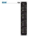
Ready
Exp
dB Headroom
24
12
Load
Comp
Fault
Limit
6
1
3
dB Headroom
24
12
6
3
Exp
Comp
Limit
2
Ready
Load
Fault
dB Headroom
24
12
6
3
Exp
Comp
Limit
3
Ready
Load
Fault
dB Headroom
24
12
6
3
Exp
Comp
Limit
4
Ready
Load
Fault
ON
DIGITAL
AMPLIFIER
MA 4
MULTICHANNEL AMPLIFIER
MA 4
IMPORTANT SAFETY INSTRUCTIONS
1. Read these instructions.
2. Keep these instructions.
3. Heed all warnings.
4. Follow all instructions.
5. Do not use this apparatus near water.
6. Clean only with a dry cloth.
7. Do not block any ventilation openings. Install in accordance with manufacturer’s instructions.
8. Do not install near any heat sources such as radiators, registers, stoves, or other apparatus (including amplifiers) that produce heat.
9. Do not defeat the safety purpose of the polarized or grounding-type plug. A polarized plug has two blades with one wider than the other. A
grounding-type plug has two blades and a third grounding prong. The wide blade or third prong is provided for your safety. If the provided plug
does not fit into your outlet, consult an electrician for replacement of the obsolete outlet.
10. Protect the power cord and plug from being walked on or pinched particularly at plugs, convenience receptacles, and the point where it exits from
the apparatus.
11. Only use attachments and accessories specified by Rane.
12. Use only with the cart, stand, tripod, bracket, or table specified by the manufacturer, or sold with the apparatus. When a cart is used, use caution
when moving the cart/apparatus combination to avoid injury from tip-over.
13. Unplug this apparatus during lightning storms or when unused for long periods of time.
14. Refer all servicing to qualified service personnel. Servicing is required when the apparatus has been damaged in any way, such as power supply
cord or plug is damaged, liquid has been spilled or objects have fallen into the apparatus, the apparatus has been exposed to rain or moisture, does
not operate normally, or has been dropped.
15. The plug on the power cord is the AC mains disconnect device and must remain readily operable. To completely disconnect this apparatus from
the AC mains, disconnect the power supply cord plug from the AC receptacle.
16. This apparatus shall be connected to a mains socket outlet with a protective earthing connection.
17. When permanently connected, an all-pole mains switch with a contact separation of at least 3 mm in each pole shall be incorporated in the
electrical installation of the building.
18. If rackmounting, provide adequate ventilation. Equipment may be located above or below this apparatus, but some equipment (like large power
amplifiers) may cause an unacceptable amount of hum or may generate too much heat and degrade the performance of this apparatus.
19. This apparatus may be installed in an industry standard equipment rack. Use screws through all mounting holes to provide the best support.
WARNING: To reduce the risk of fire or electric shock, do not expose this apparatus to rain or moisture. Apparatus shall not be exposed to dripping
or splashing and no objects filled with liquids, such as vases, shall be placed on the apparatus.
WARNING
The symbols shown below are internationally accepted symbols
that warn of potential hazards with electrical products.
CAUTION
RISK OF ELECTRIC SHOCK
DO NOT OPEN
ATTENTION: RISQUE DE CHOCS ELECTRIQUE - NE PAS OUVRIR
To reduce the risk of electrical shock, do not open the unit. No user
serviceable parts inside. Refer servicing to qualified service personnel.
This symbol indicates that a dangerous voltage
constituting a risk of electric shock is present
within this unit.
This symbol indicates that there are important
operating and maintenance instructions in the
literature accompanying this unit.
WARNING: This product may contain chemicals known to the State of California to cause cancer, or birth defects or other reproductive harm.
NOTE: This equipment has been tested and found to comply with the limits for a Class B digital device, pursuant to part 15 of the FCC Rules.
These limits are designed to provide reasonable protection against harmful interference in a residential installation. This equipment generates, uses
and can radiate radio frequency energy and, if not installed and used in accordance with the instructions, may cause harmful interference to radio
communications. However, there is no guarantee that interference will not occur in a particular installation. If this equipment does cause harmful
interference to radio or television reception, which can be determined by turning the equipment off and on, the user is encouraged to try to correct
the interference by one or more of the following measures:
• Reorient or relocate the receiving antenna.
• Increase the separation between the equipment and receiver.
• Connect the equipment into an outlet on a circuit different from that to which the receiver is connected.
• Consult the dealer or an experienced radio/TV technician for help.
CAUTION: Changes or modifications not expressly approved by Rane Corporation could void the user's authority to operate the equipment.
This Class B digital apparatus complies with Canadian ICES-003.
Cet appareil numérique de la classe B est conforme à la norme NMB-003 du Canada.
INSTRUCTIONS DE SÉCURITÉ
1. Lisez ces instructions.
2. Gardez précieusement ces instructions.
3. Respectez les avertissements.
4. Suivez toutes les instructions.
5. Ne pas utiliser près d’une source d’eau.
6. Ne nettoyer qu’avec un chiffon doux.
7. N’obstruer aucune évacuation d’air. Effectuez l’installation en suivant les instructions du fabricant.
8. Ne pas disposer près d’une source de chaleur, c-à-d tout appareil produisant de la chaleur sans exception.
9. Ne pas modifier le cordon d’alimentation. Un cordon polarisé possède 2 lames, l’une plus large que l’autre. Un cordon avec tresse de masse possède
2 lames plus une 3è pour la terre. La lame large ou la tresse de masse assurent votre sécurité. Si le cordon fourni ne correspond pas à votre prise,
contactez votre électricien.
10. Faites en sorte que le cordon ne soit pas piétiné, ni au niveau du fil, ni au niveau de ses broches, ni au niveau des connecteurs de vos appareils.
11. N’utilisez que des accessoires recommandés par Rane.
12. N’utilisez que les éléments de transport, stands, pieds ou tables spécifiés par le fabricant ou vendu avec l’appareil. Quand vous utlisez une valise de
transport, prenez soin de vous déplacer avec cet équipement avec prudence afin d’éviter tout risque de blessure.
13. Débranchez cet appareil pendant un orage ou si vous ne l’utilisez pas pendant un certain temps.
14. Adressez-vous à du personnel qualifié pour tout service après vente. Celui-ci est nécessaire dans n’importe quel cas où l’appareil est abimé : si le
cordon ou les fiches sont endommagés, si du liquide a été renversé ou si des objets sont tombés sur l’appareil, si celui-ci a été exposé à la pluie ou
l’humidité, s’il ne fonctionne pas correctement ou est tombé.
15. La fiche du cordon d’alimentation sert à brancher le courant alternatif AC et doit absolument rester accessible. Pour déconnecter totalement
l’appareil du secteur, débranchez le câble d’alimentation de la prise secteur.
16. Cet appareil doit être branché à une prise terre avec protection.
17. Quand il est branché de manière permanente, un disjoncteur tripolaire normalisé doit être incorporé dans l’installation électrique de l’immeuble.
18. En cas de montage en rack, laissez un espace suffisant pour la ventilation. Vous pouvez disposer d’autres appareils au-dessus ou en-dessous de celuici, mais certains (tels que de gros amplificateurs) peuvent provoquer un buzz ou générer trop de chaleur au risque d’endommager votre appareil et
dégrader ses performances.
19. Cet appareil peut-être installé dans une baie standard ou un chassis normalisé pour un montage en rack. Visser chaque trou de chaque oreille de
rack pour une meilleure fixation et sécurité.
ATTENTION: afin d’éviter tout risque de feu ou de choc électrique, gardez cet appareil éloigné de toute source d’humidité et d’éclaboussures quelles
qu’elles soient. L’appareil doit également être éloigné de tout objet possédant du liquide (boisson en bouteilles, vases,…).
ATTENTION
CAUTION
RISK OF ELECTRIC SHOCK
DO NOT OPEN
ATTENTION: RISQUE DE CHOCS ELECTRIQUE - NE PAS OUVRIR
Afin d’éviter tout risque de choc électrique, ne pas ouvrir l’appareil.
Aucune pièce ne peut être changée par l’utilisateur. Contactez un
SAV qualifié pour toute intervention.
Les symboles ci-dessous sont reconnus internationalement
comme prévenant tout risque électrique.
Ce symbole indique que cette unité utilise un
voltage élevé constituant un risque de choc
électrique.
Ce symbole indique la présence d’instructions
d’utilisation et de maintenance importantes dans le
document fourni.
REMARQUE: Cet équipement a été testé et approuvé conforme aux limites pour un appareil numérique de classe B, conformément au chapitre 15
des règles de la FCC. Ces limites sont établis pour fournir une protection raisonnable contre tout risque d’interférences et peuvent provoquer une
énergie de radiofréquence s'il n'est pas installé et utilisé conformément aux instructions, peut également provoquer des interférences aux niveaux
des équipements de communication. Cependant, il n'existe aucune garantie que de telles interférences ne se produiront pas dans une installation
particulière. Si cet équipement provoque des interférences en réception radio ou télévision, ceci peut être detecté en mettant l'équipement sous/hors
tension, l'utilisateur est encouragé à essayer de corriger cette interférence par une ou plusieurs des mesures suivantes:
• Réorienter ou déplacer l'antenne de réception.
• Augmenter la distance entre l'équipement et le récepteur.
• Connecter l'équipement à une sortie sur un circuit différent de celui sur lequel le récepteur est branché.
• Consulter un revendeur ou un technicien radio / TV expérimenté.
ATTENTION: Les changements ou modifications non expressément approuvés par Rane Corporation peuvent annuler l'autorité de l'utilisateur à
manipuler cet équipement et rendre ainsi nulles toutes les conditions de garantie.
Cet appareil numérique de classe B est conforme à la norme Canadienne ICES-003.
Cet appareil numérique de classe B est conforme à la norme Canadienne NMB-003.
OPERATORS MANUAL
MA 4
MULTICHANNEL AMPLIFIER
1
2
3
4
ON
3
Limit
Fault
3
Limit
Fault
3
Limit
Fault
3
Limit
Fault
6
Comp
Load
6
Comp
Load
6
Comp
Load
6
Comp
Load
Exp
Ready
Exp
Ready
Exp
Ready
Exp
Ready
12
12
12
24
24
dB Headroom
12
24
dB Headroom
MA 4
DIGITAL
AMPLIFIER
24
dB Headroom
dB Headroom
Quick Start
Basic MA 4 operation is straightforward:
1. The universal switching power supply works with 100 to 240 VAC, 50/60 Hz.
2. Make sure the front panel power switch is off (the unit consumes 5 watts in standby mode).
3. Connect balanced inputs (rear panel).
4. Set SENSITIVITY controls to +22 (see why on page Manual-2) (rear panel).
5. Turn the Downward EXPander ON (rear panel).
6. Set COMPressor to 10 dB (rear panel).
7. Select the appropriate HIGH PASS filter frequency (20, 40, 60 or 80 Hz on rear panel).
8. Connect speaker loads (rear panel).
9. Make sure you have adequate ventilation around the unit – see Safety Instructions.
10. Turn ON the front panel power switch. You’re good to go!
Metering shows the status of the amplifier at a glance (see page Manual-3). Headroom (with any load), dynamics control, Fault status
and Load status are indicated for each channel.
Extra Credit
For remote turn-on, fault reporting and back-up amplifier operations, and remote level control wiring, see page Manual-4.
For FAULT FLAG operation (applications and reported faults), see page Manual-3.
MADE IN U.S.A.
RANE CORP.
MA 4
OUTPUTS
COMMERCIAL AUDIO
EQUIPMENT 24TJ
4
INT EXT
3
LOAD
R
Class 2 Wiring
INT EXT
INT EXT
LOAD
+ – + – + – + –
MODE
FAULT
FLAG
INT EXT
2
1
LOAD
LOAD
+ – + – + – + –
Active Low
4 3 2 1
HIGH-PASS
20Hz
40Hz
60Hz
80Hz
MASTER
COMP
SLAVE
ON
ON
INPUTS
4
REMOTE LEVEL
3
2
1
4
Use Rane VR 2 or 20 kΩ pot
Vr Vc
Vr Vc
Vr Vc
Vr Vc
3
SENSITIVITY
+ –
13
1
+
–
+ – + – + – + –
+
–
+
+ – + – + – + –
–
+
–
4
3
2
1
+ –
13
1
SENSITIVITY
+ –
13
SENSITIVITY
+ –
13
ON
22
100-240V
50/60 Hz 500 WATTS
2
SENSITIVITY
2
3
4
1
2
3
1 2 3 4 EXP ON
22
4
dBu
4
Vr Vc
Vr Vc
Vr Vc
Vr Vc
+ –
22
4
dBu
+ –
22
4
dBu
+ –
4
dBu
+ –
SOURCE 1
SOURCE 2
SOURCE 3
SOURCE 4
Installation
•
•
•
•
No rear mounting hardware required.
Allow adequate ventilation to keep ambient temperature around the amplifier below 104˚F (40˚C).
Fan cooled with inset intake on left side and inset exhaust on right side (no filter)
Amplifier heat load in Btu/hr at 100/240 VAC
º 10.2 / 13.3 Btu/hr All amplifiers in standby
º 112.3 / 95.5Btu/hr All amplifiers on, no signal
º 167 / 139 Btu/hr All amplifiers driven, pink noise, 12 watts avg. 4:1 crest
º Note: 1 watt x 3.413 = 1 Btu/hr.
WEAR PARTS: This product contains no wear parts.
Manual-1
Description & Operation
• Each channel delivers 100 watts of power into a 4 or 8Ω load (constant power).
º Average load impedance is estimated, then used to set the limiter to confine the maximum average power to 100 watts.
• Universal voltage, power-factor-corrected power supply (see figure on data sheet).
º Switch-mode power supply operates 100 to 240 VAC, 50 Hz or 60 Hz.
º Under- and over-voltage protection with inrush current management.
º The power supply features an IEC appliance inlet.
º Must be connected to a grounded mains socket-outlet.
MA 4
MADE IN U.S.A.
RANE CORP.
COMMERCIAL AUDIO
EQUIPMENT 24TJ
4
INT E
LOAD
R
+ – +
• Class D amplifiers operate at up to 85% efficiency.
º Amplifiers operate in floating Bridged configuration.
º Channels are not bridgeable.
º Balanced Inputs accept +22 dBu maximum.
FOR CONTINUED GROUNDING
PROTECTION DO NOT REMOVE
THIS SCREW.
100-240V
50/60 Hz 500 WATTS
+ – +
• Rear panel SENSITIVITY controls allow continuous adjustment from +22 dBu to +4 dBu.
º Integrated Limiter prevents clipping regardless of input level and sensitivity setting with input levels up to +22 dBu.
º The best dynamic range is achieved when all stages in a system clip at the same time. If the signal processing in front of the amplifier clips at +22 dBu, and the amplifier sensitivity is set so that it clips at + 4 dBu, you loose 18 dB of headroom.
MODE
FAULT
FLAG
Active Low
3 2 1
HIGH-PASS
20Hz
40Hz
60Hz
80Hz
MASTER
COMP
SLAVE
ON
ON
INPUTS
4
REMOTE LEVEL
3
2
4
1
SENSITIVITY
Use Rane VR 2 or 20 kΩ pot
Vr Vc
Vr Vc
Vr Vc
3
+ –
Vr Vc
13
3
2
1
13
+ –
1
SENSITIVITY
SENSITIVITY
13
+ –
13
+ –
ON
22
1
2
SENSITIVITY
2
3
4
1
2
3
1 2 3 4 EXP ON
22
4
dBu
4
Vr Vc
Vr Vc
Vr Vc
+ –
Vr Vc
22
4
dBu
+ –
22
4
dBu
4
dBu
+ –
+ –
• REMOTE DC LEVEL control inputs are provided for each channel.
º Audio taper attenuation with external linear pot (0 dB to –80 dB, –16 dB at center position).
º Clickless mute with switch (use SPST switch; connect Vc to GND to mute).
º Euroblock connector with strain relief (Vref, Vcontrol, GND).
º One pot may control all four channels by daisy-chaining the Vc of the used port to the other three ports.
•The Load-dependent Limiter eliminates voltage and current clipping, ensuring signal integrity and uninterrupted service.
º The peak signal detector for the Limiter is oversampled to insure accuracy at any frequency.
º Instantaneous attack and 3 dB per second decay.
• Average load impedance is estimated and used to determine the Limiter threshold setting.
º The front panel Load indicator (see metering) indicates the load status.
º The normal impedance range is 2 to 16 Ω. (green Load indicator on).
º Average load impedance is estimated over 180 ms and requires a minimum of 3.3 watts averaged over 180 ms.
• A soft-knee COMPressor is enabled (down) or disabled (up) for all channels using the rear panel dipswitch.
º The rms threshold is 10 dB below the Limiter threshold.
· Allows full uncompressed operation of typical program material while reducing continuous sine wave power.
· Soft knee span is 10 dB; Ratio is 3:1; Attack is 1.5 seconds; Decay is 3 dB per second.
º If the internal amplifier temperature goes above 65˚ C, the compressor is automatically set to the 10 dB setting until the
temperature drops below 55˚ C. At normal operating temperatures, the threshold setting follows the dipswitch setting.
• Downward EXPander reduces noise in the absence of signal.
OUTPUTS
MA 4
COMMERCIAL AUDIO
Class 2 Wiring
º The expander is enabled (down)
or disabled
(up) for all channels
using the rear panel dipswitch.
EQUIPMENT
24TJ
INT EXT
INT EXT
INT EXT
INT EXT
FAULT
4 time is 3
º Threshold is –70 dBFS; Ratio is 3:1; Attack
50 ms; Gain2reduction 110 dB per second. FLAG
MADE IN U.S.A.
RANE CORP.
R
ACN 001
345 482
LOAD
LOAD
• 20, 40, 60 or 80 Hz HIGH-PASS filters
º Setting affects all channels.
FOR CONTINUED GROUNDING
º Filters
are 12 dBPROTECTION
per octave,
Butterworth
alignment.
100-240V
DO NOT
REMOVE
+ – + – +
50/60 Hz 500 WATTS
Manual-2
THIS SCREW.
LOAD
LOAD
+ selected
– + – using
+ – +the– rear
+ panel
– + dipswitch.
– + – + –
are
4
Active Low
3 2 1
MODE
HIGH-PASS
20Hz
40Hz
60Hz
80Hz
MASTER
COMP
SLAVE
ON
ON
1
– + –
+ – + – + – + –
4
3
2
1
4
REMOTE
3
Use Rane VR
Vr Vc
Vr Vc
Vr Vc
Vr Vc
ON
2
3
4
1
2
3
1 2 3 4 EXP ON
4
• Individual FAULT FLAG ports are provided for each channel.
OUTPUTS
MA 4
COMMERCIAL AUDIO
MADE IN U.S.A.
Class 2 Wiring
º When a fault is detected
channels
and the appropriate front
EQUIPMENT
24TJ affected are not enabled,
RANE CORP. on power up, the channel or
INT EXT
INT EXT
INT EXT
INT EXT
2
1
panel fault indicators are lit. A detected fault is re-tested every 104seconds. 3
LOAD
LOAD
LOAD OFF.
º When a channel develops a fault while operating,
the channel shuts
down and
the outputLOAD
relay is turned
ACN 001
+ – + – + – + –
+ – + – + – + –
A detected fault is re-tested every 10 seconds.345 482
º Possible faults include: supply under-voltage, over-voltage, voltage imbalance, output short to ground, output
CONTINUED GROUNDING
short to supply, output short
to output, FOR
clock
notDOrunning,
100-240V
PROTECTION
NOT REMOVE over safe temperature.
+ – + – + – + –
+ – + – + – + –
THIS SCREW.
50/60 Hz 500 WATTS
º Channels set to Master, drive the fault flag high when no fault is present. Passive pull down pulls the fault flag low
when a fault occurs or power is lost. Slave channels read the status of the fault flag (see Master/Slave below).
º The fault flag uses 5 volt logic with high-side active drive and passive pull down. No fault = +5V. Fault = 0V.
MODE
FAULT
FLAG
R
4
Active Low
3 2 1
HIGH-PASS
20Hz
40Hz
60Hz
80Hz
MASTER
C
SLAVE
ON
1
4
3
2
1
ON
2
3
4
1
2
1 2 3 4 EXP O
• Each channel is set for MASTER (up) or SLAVE (down) operation using the rear panel dipswitch.
º Master channels write fault flag status.
º Slave channels read fault flag status.
º The Master setting is used for remote fault reporting and/or automatic redundancy switching control.
º The Slave setting is used for individual channel remote power sequencing or automatic redundancy switching.
•Internal automatic redundancy switching is provided (see page Manual-4).
OUTPUTS
MA backup
4
AUDIO
U.S.A.
º The primary amplifier channel is setMADE
to INMaster.
The
amplifierCOMMERCIAL
channel
is
Class 2 Wiring
EQUIPMENT 24TJ
RANE CORP.
INT EXT
INT EXT
INT EXT
INT EXT
set to Slave. The Master fault flag is wired to the Slave fault flag. If two different 4
3
2
1
LOAD
LOAD
LOAD
LOAD
MA 4 amplifiers are involved (recommended), also wire the faultACN
flag
grounds
001
345 482and set the
+ – + – + – + –
+ – + – + – + –
together. Drive Master and Slave audio inputs from the same source,
SENSITIVITY controls the same. Master and Slave front panel power switches
FOR CONTINUED GROUNDING
must be ON.
100-240V
PROTECTION DO NOT REMOVE
+ – + – + – + –
+ – + – + – + –
SCREW.
50/60 Hz 500 WATTS
º When a fault is detected on a Master amplifier
channel, thatTHIS
channel
is shut
down, the output relay is switched to off, internally connecting the load to the
EXTernal amplifier input. The front panel fault indicator is then lit.
º The Slave channel remains in low-power standby (Ready indicator flashing) until a fault is detected (fault flag no longer driven
high by the Master channel). When a fault is detected, the Slave channel performs a self test, switches to run mode, and closes the
output relay (takes about 500 ms). The output of the Slave channel is connected to the EXTernal amplifier input on the Master
channel.
FAU
FLA
R
• Comprehensive front panel metering is included for each channel:
º Headroom meters are four-segment. The peak signal level is compared to the limit threshold and the difference in dB is displayed
as remaining headroom. The limiter threshold is adjusted to account for the average load impedance, resulting in load compensated headroom indication.
º Red Limiter, yellow Compressor and yellow Expander indicators light when the associated dynamics control is active.
º A red Fault indicator lights when a fault is detected
º The green Load indicator is off when impedance is above 16 Ω, on when impedance is between 2 and 16 Ω and flashing when the
impedance is below 2 Ω.
º The green Ready indicator is off when the power switch is off, flashing when the power switch is on and the unit is in standby
(Slave channel with high fault flag) and on when the channel is active.
1
2
3
Limit
Fault
6
Comp
Load
Exp
Ready
12
24
dB Headroom
3
3
Limit
Fault
6
Comp
Load
Exp
Ready
12
24
dB Headroom
4
3
Limit
Fault
6
Comp
Load
Exp
Ready
12
24
dB Headroom
ON
3
Limit
Fault
6
Comp
Load
Exp
Ready
12
24
dB Headroom
Manual-3
4
Active
3 2
4
3
2
Advanced Applications
Remote Turn-on
To operate an amplifier channel in low power standby with remote turn-on, set its rear panel switch to SLAVE. External +5 volts connected to the FAULT FLAG holds the amplifier in standby. Floating the FAULT FLAG or connecting it to ground turns the channel on.
MADE IN U.S.A.
RANE CORP.
MA 4
OUTPUTS
COMMERCIAL AUDIO
EQUIPMENT 24TJ
4
INT EXT
3
LOAD
R
Class 2 Wiring
INT EXT
INT EXT
LOAD
+ – + – + – + –
MODE
FAULT
FLAG
INT EXT
2
1
LOAD
LOAD
+ – + – + – + –
4
Active Low
3 2 1
HIGH-PASS
20Hz
40Hz
60Hz
80Hz
MASTER
COMP
SLAVE
ON
ON
INPUTS
4
REMOTE LEVEL
3
2
1
4
3
SENSITIVITY
Use Rane VR 2 or 20 kΩ pot
Vr Vc
Vr Vc
Vr Vc
Vr Vc
13
+ –
1
+ – + – + – + –
+ – + – + – + –
4
3
2
1
13
+ –
1
SENSITIVITY
SENSITIVITY
13
+ –
13
+ –
ON
22
100-240V
50/60 Hz 500 WATTS
2
SENSITIVITY
2
3
4
1
2
3
dBu
4
1 2 3 4 EXP ON
22
4
Vr Vc
Vr Vc
Vr Vc
Vr Vc
22
4
dBu
+ –
22
4
dBu
+ –
4
dBu
+ –
+ –
+5V
Fault Reporting
To have an amplifier channel report a fault to a control system or back up amplifier, set it to Master. The
Fault Flag is held high (+5 volts) during normal operation and goes low (passive pull down) when a fault
occurs. For details on Fault Flag operation, see page Manual-3.
Remote Level Control inputs are provided for each channel. The Rane VR 2 or any other linear potentiometer 10k to 100k Ω may be connected to these inputs (diagram at right).
Vc
CW
GND
20 kΩ,
linear taper
Vr
SLAVE
MA 4
MA 4
MADE IN U.S.A.
RANE CORP.
OUTPUTS
COMMERCIAL AUDIO
EQUIPMENT 24TJ
4
INT EXT
3
LOAD
R
Class 2 Wiring
INT EXT
INT EXT
LOAD
+ – + – + – + –
MODE
FAULT
FLAG
INT EXT
2
1
LOAD
LOAD
+ – + – + – + –
Active Low
4 3 2 1
HIGH-PASS
20Hz
40Hz
60Hz
80Hz
MASTER
COMP
SLAVE
ON
ON
INPUTS
4
REMOTE LEVEL
3
2
1
4
Use Rane VR 2 or 20 kΩ pot
Vr Vc
Vr Vc
Vr Vc
Vr Vc
3
SENSITIVITY
+ –
13
1
+ – + – + – + –
+ – + – + – + –
4
3
2
1
+ –
13
1
SENSITIVITY
+ –
13
SENSITIVITY
+ –
13
ON
22
FOR CONTINUED GROUNDING
100-240V
PROTECTION DO NOT REMOVE
50/60 Hz 500 WATTS THIS SCREW.
2
SENSITIVITY
2
3
4
1
2
3
dBu
4
1 2 3 4 EXP ON
22
4
Vr Vc
Vr Vc
Vr Vc
Vr Vc
22
4
dBu
+ –
+ –
4
3
22
4
dBu
+ –
4
dBu
+ –
MASTER
MA 4
MA 4
MADE IN U.S.A.
RANE CORP.
OUTPUTS
COMMERCIAL AUDIO
EQUIPMENT 24TJ
4
INT EXT
3
LOAD
R
Class 2 Wiring
INT EXT
INT EXT
LOAD
+ – + – + – + –
MODE
FAULT
FLAG
INT EXT
2
1
LOAD
LOAD
+ – + – + – + –
4
Active Low
3 2 1
HIGH-PASS
20Hz
40Hz
60Hz
80Hz
MASTER
COMP
SLAVE
ON
ON
FOR CONTINUED GROUNDING
PROTECTION DO NOT REMOVE
100-240V
50/60 Hz 500 WATTS THIS SCREW.
+
–
+
ZONE 1
LEVEL
4
6
0
10
2
+ – + – + – + –
+
4
6
0
10
2
+ – + – + – + –
–
+
ZONE 3
LEVEL
8
1
SENSITIVITY
Use Rane VR 2 or 20 kΩ pot
Vr Vc
Vr Vc
Vr Vc
Vr Vc
+ –
13
4
6
0
10
2
3
2
1
+ –
13
1
SENSITIVITY
+ –
13
SENSITIVITY
+ –
13
ON
2
3
4
1
2
3
1 2 3 4 EXP ON
22
4
dBu
4
Vr Vc
Vr Vc
Vr Vc
Vr Vc
+ –
22
4
dBu
+ –
22
4
dBu
+ –
4
dBu
+ –
–
LEVEL
8
4
2
SENSITIVITY
ZONE 4
LEVEL
8
REMOTE LEVEL
3
2
22
1
–
ZONE 2
INPUTS
4
4
6
0
10
2
8
VR 2
VOLUME
REMOTES
SOURCE 1
SOURCE 2
SOURCE 3
SOURCE 4
©Rane Corporation 10802 47th Ave. W., Mukilteo WA 98275-5000 USA TEL 425-355-6000 FAX 425-347-7757 WEB rane.com
Manual-4
All features & specifications subject to change without notice. DOC 111037