1
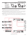
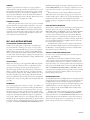
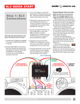
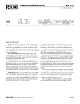
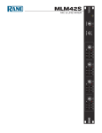
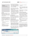
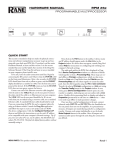
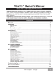
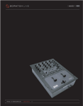
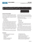
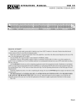
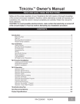
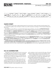
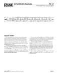
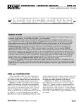
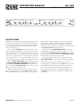
OPERATORS MANUAL
DC 22S
STEREO COMPRESSOR
INPUT
1
GATE
-60
-70
+4
OL
LEVEL
-80
-50
COMPRESSOR
-40
-30
-20
dBu
THRESHOLD
-20
-30
-40
-10
0
1.7
2
10 1.2
20
dBu
THRESHOLD
OUTPUT
INPUT
0
2
3
6
3
10
12
24
-6
-12
12
-15
1
:1
RATIO
GAIN
REDUCTION
BYPASS
6
LINK
dB
LEVEL
-70
+4
15
� MASTER
SLAVE �
GATE
-60
OL
LEVEL
-80
-50
COMPRESSOR
-40
-30
-20
dBu
THRESHOLD
-20
-30
-40
-10
0
1.7
2
10 1.2
20
dBu
THRESHOLD
OUTPUT
3
6
3
10
12
24
-6
0
-12
:1
RATIO
GAIN
REDUCTION
BYPASS
DC 22S
6
DYNAMIC
CONTROLLER
12
-15
1
15
dB
LEVEL
POWER
QUICK START
Shredded, this document makes excellent packing material. In
its present form, it makes interesting and useful reading. If you
run out of patience quickly, at least read this part to make sure
you don’t exterminate everything within a two mile radius by
doing something wrong.
First, be sure the POWER switch is off. Attach one or two
channels of Inputs and Outputs to the respective connectors on
the rear. This device uses low impedance balanced line drivers. Do
not connect the XLR “+” or “–” output pins to ground, as this may
cause the power supply to shut down. For unbalanced use, leave the
unused output pin (“+” or “–”) unterminated. OK, now you can
power up your sound system, volumes down, amp turned on last.
With the GATE THRESHOLD turned all the way down to
-80 dBu, COMPRESSOR THRESHOLD turned all the way
up to 20 dBu, COMPRESSOR RATIO turned all the way
down to 1, and the OUTPUT LEVEL control in the center at 0
dB, you have an expensive patch cord.
While sending a signal to the DC 22S, adjust the output
level of the previous device so the +4 dBu LED lights occasionally, but the OL LED does not light. If you are driving the ¼"
WEAR PARTS: This product contains no wear parts.
INPUTS with a balanced signal (tip-ring-sleeve), set the Input
Gain switch to +4 dBu (in). When driving this input with an
unbalanced signal (tip-sleeve), set this switch to –10 dBv (out).
Regardless of the type of Input, you might need to set this switch
so the INPUT LEVEL LEDs light correctly.
Now increase the COMPRESSOR RATIO to something
useful, like 2:1 (with the control set at 2, the Ratio is 2:1; at 5, it
is 5:1.) Adjust the COMPRESSOR THRESHOLD to the point
you want the Compressor to kick in. The GAIN REDUCTION
meter reads the amount of signal compression.
If you want the quiet parts to be even quieter, increase the
GATE THRESHOLD so only higher levels make it through the
Gate.
Both Gates and Compressors will activate by the source
material applied to either channel if the LINK switch is on. This
is the preferred setting for stereo program material. The channel 1 controls set both channels to the same adjustments, as the
channel 2 controls go dormant and the LEDs extinguish. If
the LINK switch is off, then both channels are independently
controllable.
Manual-1
Front Panel Description
INPUT
INPUT LEVEL indicators: With signal applied, the +4 dBu
LED may light occasionally. If the OL (overload) LED flashes,
turn the output level down on the previous device.
1
2
LEVEL
-30
-30
10 1.2
10
0
-30
1.7
-40
-30
-20
dBu
THRESHOLD
2
20
dBu
THRESHOLD
0
-6
6
-12
24
12
-15
20
dBu
THRESHOLD
OUT
3
6
3
10
LINK
2
SLAVE �
-60
-70
+4
� MASTER
GATE
OL
LEVEL
-80
-50
COMPRESSOR
12
-12
24
-15
1
:1
RATIO
GAIN
REDUCTION
BYPASS
-40
-30
-20
dBu
THRESHOLD
-20
-30
-40
-10
0
1.7
2
10 1.2
20
dBu
THRESHOLD
6
3
10
-6
12
0
-12
24
2
LINK
+4
� MASTER
SLAVE �
:1
RATIO
GAIN
REDUCTION
BYPASS
DC 22S
6
DYNAMIC
CONTROLLER
12
-15
1
15
dB
LEVEL
POWER
When the POWER LED is lit, the DC 22S is connected to a
100-240 VAC source and ready to rock.
Manual-2
d
LEV
INP
OUTPUT
3
0
-6
Channel 2 controls duplicate the controls in channel 1. These
are not active if the LINK switch is engaged.
INPUT
1
-40
15
dB
LEVEL
BYPASS
0
-30
OUTPUT
LINK
when
1 either channel’s
-80 switch
-20activates both
-40 Compressors
20
signal
exceeds
the
set
Threshold,
preserving
stereo
:1 imaging.GAIN
dBu
dBu
THRESHOLD
THRESHOLD
RATIO
Switch this ON when using
stereo material. The
channelREDUCTION
1
controls become the Master when this switch is active, rendering the channel 2 controls and indicators dead.
_____________________________________________
-10
-20
-80
10 1.2
-40
dBu
THRESHOLD
OUTPUT LEVEL control increases or decreases the output3
2
-50
-10
gain of each
Channel by
15 dB. In0the center
detent, 3gain 6will
1.7
-60
-40
-20
be unity.
12
-70
-10
-20
BYPASS switch compares the compressed and non-compressed
signal. There is one for each channel. The INPUT LEVEL
indicators remain active regardless of switch position.
INPUT
GATE
COMPRESSOR
OL
CO
COMPRESSOR
GAIN REDUCTION LEDs show the amount of average signal
reduction in dB. This aids in setting the THRESHOLD and
RATIO controls by showing how much compression is occuring.
_____________________________________________
+4
OL
LEVEL
COMPRESSOR THRESHOLD control sets the point at
which the Input signal level causes the Compressor to become
active. See Figure 1 on page Manual-4.
INPUT
GATE
COMPRESSOR RATIO control: Once the Threshold is
exceeded, the Ratio of input change to output change is deter--50
-60set
-40
mined by this control. The compressor has no1
effect when
at 1:1. But at 10:1, it takes a 10 dB input signal increase
above
-70
-30
the Threshold to produce a 1 dB increase in+4
Output
OL Gain. See
-80
-20
Figure 2 on page Manual-4.
1
-50
-60
-70
+4
GATE THRESHOLD control sets the point at which the Input
signal level causes the Gate to become active.
_____________________________________________
LEVEL
GATE
LEV
Rear Panel Description
DC 22S
WIRING
3-PIN XLR:
DE IN U.S.A.
ANE CORP.
• PIN 2 = (+), • PIN 3 = (–),
• PIN 1 = CHASSIS (SHIELD)
OUTPUT
INPUT
2
2
1/4" PHONE, BALANCED:
-10 dBV
+4 dBu
• TIP = (+), • RING = (–),
• SLEEVE = CHASSIS (SHIELD)
N 001 345 482
This device co
15 of the FCC
is subject to t
conditions: (1)
not cause harm
and (2) this de
any interfer
including inter
cause undesire
1/4" PHONE, UNBALANCED:
• SEE THE RANENOTE: SOUND
SYSTEM INTERCONNECTION
BALANCED
BAL/UNBAL
BALANCED
BAL/UNBAL
INPUTS 1 and 2: Choose between the balanced XLR or the balanced/unbalanced ¼" TRS jacks, but only use one. Inserting a ¼"
TS jack will work—however—we recommend using balanced lines, especially when connecting any cable over 10 feet (3 meters)
in length. Consult the Sound System Interconnection RaneNote provided with this manual.
INPUTS 1 and 2 Gain Trim Switch: In its +4 dBu position, the Input gain of the respective channel is unity. In the -10 dBV position, the input gain is increased by 12 dB (although mathematically suspicious, it really is 12 dB, not 14 dB) to compensate for
certain recording devices. This switch must be in the +4 dBu position for front panel calibration accuracy.
OUTPUTS 1 and 2 are delivered by the balanced XLR or the unbalanced ¼" TS jacks. Using both types of Outputs are permissible
to drive two devices, such as an amplifier and a recorder. This device uses low impedance balanced line drivers. Do not connect the
XLR “+” or “–” output pins to ground, as this may cause the power supply to shut down. For unbalanced use, leave the unused output pin
(“+” or “–”) unterminated.
OUTPUTS
LEFT
RIGHT
INPUTS
LEFT
RIGHT
0
10
LEVEL
0
10
LEVEL
RIGHT SPEAKER
STEREO AMP, HIGH
AC 22S
COMMERCIAL AUDIO
100-240 V
EQUIPMENT 24TJ
50/60 Hz 7 WATTS
HIGH OUT
LOW OUT
CH 2 IN
STEREO 2-WAY
MADE IN U.S.A.
RANE CORP.
SUBWOOFER SWITCH MUST
BE SET TO 2- CHANNEL
FOR MONO 3-WAY
R
MODE
ACN 001 345 482
HIGH OUT
MONO SUB: OMIT
MID OUT
MONO 3-WAY
OMIT MONO
HIGH OUT
LOW OUT
CH 1 IN
OMIT MONO
MONO SUB OUT
LOW OUT
PIN 2: POSITIVE
PIN 3: NEGATIVE
PIN 1: CHASSIS GND
SUBWOOFER
2-CHANNEL
MONO SUB
MONO
3-WAY IN
This device complies with Part
15 of the FCC Rules. Operation
is subject to the following two
conditions: (1) this device may
not
cause
harmful
interference, and (2) this
device must accept any
interference
received,
including interference that may
cause undesired operation.
AC 22S STEREO 2-WAY CROSSOVER
100-240 V
50/60 Hz 7 WATTS
ME 15S
COMMERCIAL AUDIO
EQUIPMENT 24TJ
CHANNEL 2
MADE IN U.S.A.
RANE CORP.
OUTPUT
WIRING
INPUT
ACN 001 345 482
LEFT SPEAKER
CHANNEL 1
This device complies with Part 15 of
the FCC Rules. Operation is subject
to the following two conditions:
(1) this device may not cause
harmful interference, and (2) this
device must accept any interference
received, including interference that
may cause undesired operation.
TIP / PIN 2 = POSITIVE
RING / PIN 3 = NEGATIVE
SLEEVE = SIGNAL GROUND
PIN 1 = CHASSIS GROUND
R
OUTPUT
INPUT
ME 15S STEREO EQUALIZER
DC 22S
COMMERCIAL AUDIO
EQUIPMENT 24TJ
MADE IN U.S.A.
RANE CORP.
WIRING
3-PIN XLR:
OUTPUT
INPUT
2
2
• PIN 2 = (+), • PIN 3 = (–),
• PIN 1 = CHASSIS (SHIELD)
1/4" PHONE, BALANCED:
R
ACN 001 345 482
100-240 V
50/60 Hz 7 WATTS
-10 dBV
+4 dBu
• TIP = (+), • RING = (–),
• SLEEVE = CHASSIS (SHIELD)
1/4" PHONE, UNBALANCED:
• SEE THE RANENOTE: SOUND
SYSTEM INTERCONNECTION
BALANCED
BAL/UNBAL
BALANCED
OUTPUT
INPUT
1
1
This device complies with Part
15 of the FCC Rules. Operation
is subject to the following two
conditions: (1) this device may
not cause harmful interference,
and (2) this device must accept
any interference received,
including interference that may
cause undesired operation.
-10 dBV
+4 dBu
BAL/UNBAL
BALANCED
BAL/UNBAL
BALANCED
BAL/UNBAL
DC 22S STEREO COMPRESSOR
MONO SUBWOOFER
TTM 56S
COMMERCIAL AUDIO
EQUIPMENT 24TJ
MADE IN U.S.A.
RANE CORP.
U.S. PATENT 6,813,361
R
POWER
TTM 56S MIXER
ACN 001 345 482
MASTER
OUTPUTS
L
AUX
OUT
FlexFX
L
IN
PHONO
GROUNDS
PGM 2
4
L
1
L
R
R
BALANCED
2
L
SEND
RETURN
R
100-240V
50/60 Hz
20 WATTS
MIC
OUT
R
IN
UNBALANCED
4
R
3
BALANCED
PGM 1
3
L
PHONO
4321
EFFECTS
4321
LINE
TIP = SEND
RING = RTN
R
2
OUTPUTS
1
LEFT
RIGHT
INPUTS
LEFT
RIGHT
0
10
LEVEL
0
10
LEVEL
MONO OR BRIDGED AMP, MONO SUB
System wiring example for a DJ system
Manual-3
OPERATING INSTRUCTIONS
A PRIMER
Let’s start with what a compressor actually does. No matter how
you cut it, this is an automatic volume control. It is a hand on
a knob, turning the volume down and turning it up again. The
hand is really quick and really accurate, but it’s just turning a
volume control.
When the input signal reaches a level set by the COMPRESSOR THRESHOLD control, the compressor begins turning
down the signal by an amount determined by the RATIO
control. The DC 22S, like most compressors, operates by making the loud signals quieter, but does not make the quiet parts
louder. However, by keeping the loud signals under control, the
entire system may be turned up when necessary to make the
quiet parts louder.
PRE-FLIGHT CHECKLIST
Before proceeding, it’s a good idea to turn the control knobs to
the following positions:
1. GATE THRESHOLD control......fully counterclockwise
2. COMPRESSOR THRESHOLD....fully clockwise
3. COMPRESSOR RATIO...............fully counterclockwise
4. BYPASS switches......................ACTIVE (out)
5. OUTPUT LEVEL.........................0 dB
This renders the DC 22S with no compression, allowing signal through at unity gain. No change occurs with the BYPASS
switch in or out.
INPUT LEVEL
Before making any Threshold adjustments, set the ouput level of
the previous device so the +4 dBu LED lights occasionally, and
the OL LED does not light. Be aware that changes to the Input
Level will affect the Thresholds.
GATE THRESHOLD
The threshold is the point at which gain adjustment begins. When
the input signal is below the threshold, the DC 22S attenuates
the signal at a 2:1 ratio, making the quiet parts twice as quiet.
When the signal is above the Gate Threshold, the Gate is open,
like a straight wire.
AUDIO PRECISION amp
0
AMPL(dBr) vs AMPL(dBu)
09 AUG 101 14:51:28
-10
RATIO
AUDIO PRECISION
20
AMPL(dBr) VS AMPL(dBu)
09 AUG 101 14:34:57
10
10
O 0
U
T -10
P
U -20
T
0
-10
-20
-30
-30
d
B -40
u
-40
-50
-60
-60
-50
-40
-30
-20
-10
INPUT (dBu)
0
10
20
Figure 2. With the Ratio set to ∞, the DC 22S acts as a Limiter. This
graph shows Limiter gain reduction above various Compressor
Thresholds at 10 dBu, 0 dBu, -10 dBu, etc.
Once the Threshold is exceeded, the increase in output compared
to the input signal increase depends on the RATIO setting. An
ordinary preamp set for unity gain or a straight wire has a ratio
of 1:1, that is, the output level tracks the input level perfectly. A 2
dB change at the input produces a 2 dB change at the output.
For a 10:1 Ratio, a 10 dB blast at the input would rise only
1 dB at the output – heavy compression. Kinder, gentler ratios
are in the 2:1 to 3:1 range. Limiting, with no increase in signal
above the Threshold, occurs at ∞:1. Figure 3 illustrates various
Ratios.
AMPL(dBr) vs AMPL(dBu)
AUDIO PRECISION
20
09 AUG 101 14:45:47
-60
d -30
B
u -40
-70
-50
-50
-80
-80
-70
-60
-50
-40
-30
INPUT (dBu)
-20
-10
0
Figure 1. With a fixed Ratio set to 2:1, this graph shows gain reduction
below various Gate Thresholds at -20 dBu, -30 dBu, -40 dBu, etc.
Manual-4
-60
1:1
1.2:1
10
O
U 0
T
P -10
U
T -20
O -20
U
T -30
P
U -40
T
d
B
u
COMPRESSOR THRESHOLD
The threshold is the point at which gain adjustment begins. When
the input signal is below the threshold, the Compressor section
acts like a straight wire. When the signal is loud enough to cross
the Compressor Threshold, the compressor is active and turns
the volume down. Various Threshold points are illustrated in
Figure 1. How much it gets turned down is determined by the
RATIO control ( Figure 1 shows a Ratio set at 2:1).
1.5:1
2:1
3:1
6:1
∞:1
-60
-50
-40
-30
-20
-10
INPUT (dBu)
0
10
20
FIgure 3. Threshold at -40 dBu. Ratios of 1:1, 1.2:1, 1.5:1, etc.
Vertical axis = output level, horizontal axis = input level.
LIMITING
A limiter is a special form of compressor set up especially to
reduce peaks for overload protection. In other words, it’s a compressor with a maximum ratio. A compressor is used to change
the dynamics for purposes of aesthetics, intelligibility, recording or broadcast limitations. Once the threshold of a limiter is
reached, no more signal increase is allowed. The DC 22S acts as
a limiter when set at a very high ratio of 10:1.
LINKING IN STEREO
When using the DC 22S as a true stereo processor, with left
signal in Channel 1 and right signal in Channel 2, it is recommended to turn the LINK switch on to prevent large balance
and image shifts. While LINKed, both Channels attenuate by
exactly the same amount when either Compressor works, maintaining correct stereo imaging. Only Channel 1's controls are
active, Channel 2 becomes the slave.
DC 22S APPLICATIONS
TWO CHANNEL COMPRESSOR/LIMITER
In this case, the audio path on Channel 1 is completely separate from Channel 2, allowing you to use it as a stereo unit or
for doing two completely different processes to two completely
different signals. For stereo use, the front panel LINK switch
allows you to link Channels. When either Channel’s Threshold
is reached, both channels compress equally, preserving the stereo
image. Channel 1’s Threshold and Ratio settings will affect both
Channels.
GUITAR & BASS
Where does the unit go in the signal chain? Well, that depends
on how you want it to function. If it’s a comp/limiter for the
input signal, it would go after the guitar (if the guitar has a
line-level output) and before the preamp. If it’s to function as a
limiter to protect the speakers in the rig, it would go after the
preamp and before the power amp. Another method is to insert
the unit in the effect loop of the preamp. This allows the bass
signal to be affected by the pre-amp first, then the comp/limiter,
and then sent to the power amp. This can be desirable with tube
pre-amps.
RECORDING
Use it on bass guitar, piano, drums, or vocals—as an effect or to
tailor dynamic range for a particular recording medium. Patch
it between line-level devices or in your mixer inserts or “loops”.
The DC 22S gives you more control and a less tortured sound,
and keeps instruments sounding “up-front.” In digital recording,
compress an extremely wide dynamic range into a signal that
won’t go into digital overload, i.e. severe clipping. This is really
valuable during a live digital recording when you just don’t know
how loud it may get, and digital distortion can ruin an otherwise
good take. Set both the COMPRESSOR THRESHOLD and
RATIO relatively high, just enough to limit the peaks. Set the
GATE THRESHOLD very low, though you might want to raise
it just above the noise floor to get rid of tape hiss or processor
noise.
Of special interest are instruments which have large level
differences in their tonal ranges. String pops on a bass are one
example, shrill peaks on a flute are yet another. The higher tones
require more breath and can seem much louder than lower
pitches. Another good application would be a drum mix or vocal
submix.
LONG DISTANCE LINE DRIVER
The DC 22S is excellent as a line level amp for driving long lines
(from the mixer to the stage for instance). With the COMPRESSOR switch in the BYPASS position, the INPUT LEVEL
control and the output amplifiers remain in the circuit. This
provides a very low distortion, low noise line driver. Balanced
XLR connections are recommended for the long run from the
DC 22S's outputs (anything over 10 feet [3 meters]). A balanced
piece of equipment (equalizer or amplifier) must be used at the
receiving end of this long line.
For unbalanced systems, use the ¼" inputs on the DC 22S
and use the balanced XLR outputs to run the long distance. See
the RaneNote “Sound System Interconnection” included with
this manual for proper cable wiring.
SOUND SYSTEM WITH COMPRESSION
Let’s run a stereo system with compression. See the wiring diagram on page Manual-3.
Patch the DC 22S Compressor Inputs from the program
source or mixer outputs, and send the DC 22S Outputs to the
system equalizer (if you have one), and then on to the crossover
inputs (if you have one). Set the equalizer and crossover Inputs to
unity gain. Set the LINK switch to ON, and adjust the CHANNEL 1 COMPRESSOR THRESHOLD and RATIO controls
to keep the entire system dynamic range under control. Locating
the compressor before the equalizer results in correct spectral
balance during compression.
DRIVER PROTECTION
To individually limit Low and High drivers in a biamped system,
connect the Crossover Low Output into one DC 22S Input, and
the High Output into the other DC 22S Input. The DC 22S
Outputs go right to the respective low and high frequency power
amplifier inputs. For a stereo configuration use two DC 22S
Stereo Compressors. Be sure the LINK switch is OFF. Set the
RATIO controls to 10:1.
Assuming your input signal has peaks in excess of -20 dBu,
you should be able to rotate the COMPRESSOR THRESHOLD controls and see some GAIN REDUCTION meter action.
You should begin to hear the difference. Leave these controls at
whatever level is appropriate for your application. For the most
precise settings, see the section on the next page.
Manual-5
DRIVER PROTECTION FINE TUNING
1. Determine the driver’s maximum continuous average power rating in watts (W) (specified by the manufacturer).
2. Determine the driver impedance “z” in ohms (specified by the manufacturer).
3. Using the data in steps (1) and (2) above, calculate the maximum signal level in dBu that the driver can handle.
Max dBu = 20*log(√ (w*z)/.775).
4. Determine the gain of the amplifier in dB (if the amplifier has a level control , you may wish to measure the gain). If, i.e., you put
1V in, how many volts come out? Then convert to dB (20 log gain).
5. Subtract the gain of the amplifier in dB from the answer in step (3) to obtain the correct COMPRESSOR THRESHOLD.
6. Set the RATIO to 10:1.
NOTES
Any change in amplifier sensitivity setting will effect the power limit to the driver.
If the DC 22S is placed just before the amplifier, no other system levels will effect the power limit setting.
EXAMPLE
1. Driver power rating: w = 100 watts.
2. Driver impedance: z = 4 ohms.
3. 20*log(√(w*z)/.775) = 28.2 dBu.
4. Amplifier gain is 30 dB ( 1V in equals 31.6 V out).
5. Set the COMPRESSOR THRESHOLD control to 28.2 dBu-30 dB = -1.8 dBu.
6. Set the RATIO control to 10:1.
©Rane Corporation 10802 47th Ave. W., Mukilteo WA 98275-5098 TEL 425-355-6000 FAX 425-347-7757 WEB www.rane.com
Manual-6
All features & specifications subject to change without notice.