1
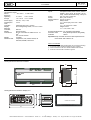
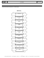
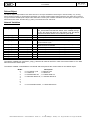
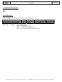
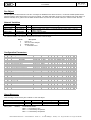
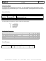
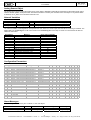
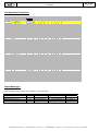
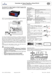
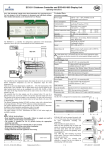
EC3-33x
User Manual
Rev. 4 - 14.01.2003
EC3-33x Coldroom Controller with EX5
EC3-33x
User Manual
A.6.5.063E - Rev 4
The EC3-33x coldroom controller is a universal controller for
refrigeration applications with an electronic stepper motor
expansion valve like the EX5. The controller has six
temperature inputs for coil in, coil out, air in, air out and defrost
termination temperatures. The sixes temperature input is a
universal temperature input. For measurement of the saturation
pressure a PT3 pressure sensor with 4 – 20 mA interface can
be connected to the controller. The controller has four relay
outputs, one defined for compressor control, one defined for
defrost heater control, one defined for an alarm output and one
as a universal relay output. The TRIAC outputs is defined for
fan control. The TRIAC can drive 24V / 230V 4A. The controller
has four digital inputs for 24V AC/ DC or 230V AC. One input is
defined for compressor failure, one input is defined for a door
contact and two inputs are free for universal purpose. The
stepper motor interface can drive stepper motor with 24V DC
and 0.7 A. The optional display can show values with a decimal
point in the range between -19.9 and +19.9°C otherwise without
decimal point. An IR receiver for the optional IR remote control
unit is build in. For communication purposes, an Echelon
LONWorks interface is installed. Two transceiver types are
available RS485 or FTT10A. The supply voltage is 24 VAC.
Transformers for 230V or 110V mains supply are available as
options.
DISPLAY ECD-001:
The data to be shown on the display can be selected by the user.
In case of on alarm, the alarm code is displayed alternately with the
selected data. The alarm code can be inhibited by the user. To
scroll through all possible displayable data press the SEL button.
The display will show for one second the numerical identifier of the
data and then the selected data. After two minutes the display will
return to the by /1 selected data.
NEURON ID / SERVICE BUTTON:
• Display :
Press the button for app. 1 second to send the Neuron ID.
An LED in the left upper corner will indicate the transmission
of the Neuron ID.
Controller:
There is a small hole left of the network connector. Use a
small pen or screwdriver to press the switch behind the hole.
An LED close to the switch will light to indicate the
transmission of the Neuron ID.
PARAMETER MODIFICATION:
• Press or to show the code of the parameter that has to
be changed;
• Press SEL to display the selected parameter value;
• Press or to increase or decrease the value;
• Press SEL to temporally confirm the new value and display its
code;
Repeat the procedure from the beginning "press or to
show..."
To exit modifying the parameters with the new values:
• Press PRG to confirm the new values and exit the parameters
modification procedure.
To exit without modifying any parameter:
• Do not press any button for at least 60 seconds (TIME OUT).
• Press “ESC” on IR remote control.
DEFROST ACTIVATION:
A defrost cycle can be activated locally from the keypad :
• Press the button for more than 5 seconds
• A flashing 0 is displayed
• Press or until 12 is displayed; (password)
• Press SEL to confirm password
• The defrost cycle is activated
CLEAR ALARMS:
A defrost termination or fan activation alarm can be cleared
from the keypad :
• Press or for more than 5 seconds.
• “CL” will be shown in the display to indicate that the
alarms are cleared.
INDICATIONS ON THE DISPLAY :
COMPRESSOR
Logical status of the compressor
relay
FAN
Logical status of the fan relay
DEFROST
Logical status of the defrost heater
relay
ALARM
Alarm condition
LOAD DEFAULT PARAMETERS:
• Use a small pen or screwdriver to press the service pin switch
on the controller and switch on the power supply on. The
EC3-21x will be reset to default parameters.
PARAMETERS:
The configuration parameters are protected by a numerical
password. The default password is “12”. To select the
parameter configuration :
• Press the PRG button for more than 5 seconds
• A flashing 0 is displayed
•
•
•
•
Press or until 12 is displayed; (password)
Press SEL to confirm password
The first modifiable parameter code is displayed (/1).
To modify parameters see Parameters modification below.
2
Emerson Electric GmbH & Co - ALCO CONTROLS - Heerstr. 111 - D-71332 Waiblingen - Germany - Tel.: ..49 (0) 7151 509 0 - Fax: 49 (0) 7151 509 200
EC3-33x Coldroom Controller with EX5
EC3-33x
User Manual
A.6.5.063E - Rev 4
LIST OF PARAMETERS
Parameter
DISPLAY PARAMETERS
Value to be shown on display
No alarms
Temperature unit
Decimal point
Display during defrost
Temperature alignment for /1 = 0
Values
Min Max Unit Def
0
11
0
0
1 flag 0
0
1 flag 0
0
1 flag 0
0
2 flag 0
-20.0+20.0 K 0.0
F
F1
F2
F3
F4
F5
Fd
Ft
Parameter
FAN PARAMETERS
Fan start-up sequence after defrost
Fan status during no cooling
Fan status during defrost
Fan stop delay time by no cooling
Fan status during cleaning
Fan start delay time after defrost
Fan on temperature after defrost
Min
0
0
0
0
0
0
-40
Values
Max Unit Def
4
0
2
0
1 flag 0
30 min 0
1 flag 0
30 min 0
40 °C
0
A
A0
A1
A2
A3
c
c0
c1
c2
c3
COMPRESSOR PARAMETERS
Delay first start of compressor
Cycle time of compressor
Min. stop time of compressor
Min. run time of compressor
Min
0
0
0
0
Max
15
15
15
15
r
r0
r1
r2
r3
u
u0
u1
u2
u3
u4
u5
u6
u7
u8
uu
ut
SUPERHEAT PARAMETERS
Refrigerant
Correction glide / pressure drop
MOP control
MOP temperature
Control mode
Superheat init set-point
Superheat set-point min
Superheat set-point max
Saturation temperature
Start opening
Valve type
Min Max
0
4
-20.0 20.0
0
1
-40 40
0
2
u6 u7
3
u7
u6 20
0
1
50 100
0
3
H
H2
OTHER PARAMETERS
Min Max Unit Def
Keyboard and IR remote control
0
3
3
0 = all disabled (Caution, access to controller only via LON networ
possible)
1 = Keyboard enabled
2 = IR remote control enabled
3 = Keyboard and IR remote control enabled
IR remote control access code
0 199 0
Password
0 199 12
/
/1
/2
/5
/6
/7
/C
ALARM PARAMETERS
Min Max Unit Def
Mean factor alarm temperature
0 100 % 100
Low temperature alarm delay
0 180 min 5
High temperature alarm delay
0 180 min 5
High temperature alarm delay after
0 180 min 10
defrost
Ad Door alarm delay
0 180 min 2
AH High temperature alarm threshold
AL 70 °C/K 40
AL Low temperature alarm threshold
-50 AH °C/K -40
At Type of alarm threshold values
0
1 flag 0
0 = absolute temperatures °C
1 = relative temperatures K to setpoint
Min Max Unit Def
0
15 flag 6
-40 r2 °C -40
r1 60 °C 40
0
1 flag 1
r4
r6
r7
r8
r9
rd
St
THERMOSTAT PARAMETERS
Door contact function
Min set-point value
Max set-point value
Day / night control
0 = off
1 = on
Thermostat mode
Set-point night operation
Difference night operation
Mean factor day operation
Mean factor night operation
Difference day operation
Set-point day operation
0
r1
0.1
0
0
0.1
r1
4
r2
20.0
100
100
20.0
r2
1
°C 4.0
K 2.0
% 100
% 50
K 2.0
°C 2.0
d
d0
d1
d2
d3
d4
d5
d6
d7
d8
d9
dd
dH
dt
dP
dI
dU
DEFROST PARAMETERS
Defrost mode
Termination by time / temperature
Defrost termination sensor
Pulsed defrost
Defrost at power up
Delay for power up defrost
Pump down delay
Drain delay
Injection delay
Demand defrost mode
Pulsed defrost difference
Pulsed defrost set-point
Defrost termination temperature
Maximal defrost duration
Defrost interval
Start up delay by synchronization
Min
0
0
0
0
0
0
0
0
0
0
1
-40
-40
0
0
0
Max
2
3
1
1
1
180
180
180
180
2
20
dt
90
180
192
180
Unit Def
1
0
flag 1
flag 0
flag 0
min 0
sec 0
min 2
sec 0
0
K
2
°C
5
°C
8
min 30
h
8
min 30
H3
H5
Unit Def
min 0
min 0
min 0
min 0
Unit
K
flag
°C
K
K
K
flag
%
-
3
Emerson Electric GmbH & Co - ALCO CONTROLS - Heerstr. 111 - D-71332 Waiblingen - Germany - Tel.: ..49 (0) 7151 509 0 - Fax: 49 (0) 7151 509 200
Def
3
0.0
0
0
1
6
3
15
1
100
0
EC3-33x Coldroom Controller with EX5
EC3-33x
User Manual
A.6.5.063E - Rev 4
Remarks
•
/1 Value to be shown on display
0 = Thermostat control temperature, Alignment factor /C will
only work with this temperature display
1 = Air in temperature
2 = Air out temperature
3 = Alarm temperature
4 = Defrost termination temperature
5 = Coil in temperature
6 = Coil out temperature
7 = Superheat
8 = Valve opening
9 = Defrost status
10 = not used
11 = not used
•
/2 No alarms
0 = alarms will be shown on display
1 = alarms will not be shown on display
•
/5 Temperature unit for display
0 = °C
1 = °F
•
/6 Display with decimal point
0 = yes, in the range from –19.9 to 19.9
1 = no
•
/7 Display during defrost
0 = “df”
1 = “df” + defrost termination temperature
2 = “df” + control temperature
•
r0 Door contact function
Contact closed or nviDoor = ST_ON
Value = Cooling + Alarm + Timer + Action
•
•
•
Temperature = Airin − (( Airin − Airout )* MeanFactor / 100)
Mean factor = 0 , Temperature = Air in
Mean factor = 100, Temperature = Air out
•
d0 Defrost mode
0 = natural defrost, defrost heater not activated
pulsed defrost not possible, synchronization by bindings
1 = forced defrost, defrost heater activated, pulsed
defrost possible, synchronization by bindings
2 = forced defrost, defrost heater activated, pulsed
defrost possible, synchronization by nviStartUp
•
d1 Termination by temperature / time
0 = termination by temperature, termination by time
will generate an alarm
1 = termination by time, termination by temperature
will generate an alarm
2 = first, what ever comes first time or temperature,
no alarm
3 = last, by time and temperature, no alarm
•
d2 Defrost termination sensor
0 = defrost termination sensor
1 = air out sensor
•
d3 Pulsed defrost
0 = off, no pulsed defrost, heaters switched off at
defrost termination temperature dt or max. time
dP whatever is selected
1 = on, pulsed defrost, dd and dH in use, heaters are
switched off at dH and switched on again at
dH – dd
•
d6 Pump down delay
The compressor will run during pump down delay while
the valve is closed
•
d8 Injection delay
The valve is open during injection delay while the
compressor is not running
•
d9 Demand defrost mode
0 = demand defrost off
1 = on
2 = on + defrost if no demand defrost within dI
•
F1 Start up sequence after defrost
0 = on
1 = delayed by time Fd, error on temperature
2 = by temperature Ft, error on time
3 = first, whatever comes first time or temperature,
no alarm
4= last, time and temperature must come, no alarm
•
F2 Fan status during no cooling
0 = on
1 = off
2 = delayed by F4
Cooling 0 = cooling
1 = no cooling
Alarm
0 = temperature alarm on, door alarm
2 = temperature alarm off, door alarm off
Timer
0 = Timer not started
4 = Timer started
Action when timer expired
0 = temperature alarm on, door alarm
8 = temperature alarm on, door alarm,
cooling restart if “Cooling = 1”
•
r4 Thermostat mode
0 = off, no thermostat function, continues cooling
air in and air out sensor monitoring off, no temp. alarms
generated
1 = cooling, deadband control
cut in = set-point + difference
cut out = set-point
2 = cooling, modulating thermostat
cut in = set-point
cut out = set-point – difference /2
3 = heating, deadband control
cut in = set-point – difference
cut out = set-point
4 = on, external control by nviValve
air in and air out sensor monitoring off, temp. alarms
will be generated
A0 Mean factor alarm temperature
r8 Mean factor day operation
r9 Mean factor night operation
Temperature calculation by the following formula
4
Emerson Electric GmbH & Co - ALCO CONTROLS - Heerstr. 111 - D-71332 Waiblingen - Germany - Tel.: ..49 (0) 7151 509 0 - Fax: 49 (0) 7151 509 200
•
F3 Fan status during defrost
0 = on
1 = off
•
F5 Fans status during cleaning
0 = off
1 = on
•
u0 Refrigerant
0 = R22
1 = R134a
2 = R507
3 = R404A
4 = R407C
•
u1 Correction
Glide
= positive Values
Pressure drop = negative Values
•
u2 MOP Control
0 = off
1 = on
•
u4 Control Mode
0 = off
1 = fixed superheat
2 = adaptive superheat
•
u8 Saturation Temperature
0 = Coil in temperature
1 = Pressure
•
ut Valve type
0 = EX5
1 = EX6
2 = EX7
3 = EX8
EC3-33x Coldroom Controller with EX5
EC3-33x
User Manual
A.6.5.063E - Rev 4
Note: Concerning the indicated parameters, it is recommended to check,
before installing, if the factory value is suitable for the required use
5
Emerson Electric GmbH & Co - ALCO CONTROLS - Heerstr. 111 - D-71332 Waiblingen - Germany - Tel.: ..49 (0) 7151 509 0 - Fax: 49 (0) 7151 509 200
EC3-33x Coldroom Controller with EX5
EC3-33x
User Manual
A.6.5.063E - Rev 4
ALARMS AND MESSAGES
ALARM CODES
MESSAGES
E0
E1
E2
E3
E4
E5
E6
---
Coil in sensor failure
Coil out sensor failure
Air in sensor failure
Air out sensor failure
Defrost termination sensor failure
Temp. 6 sensor failure
Pressure sensor failure
• No sensor connected.
• The sensor cable is broken or short circuited.
•
In
•
Id
Er
Data error
•
• Data send to the display is out of range.
Ad
Door open alarm
AH
High temperature alarm
OF
AL
Low temperature alarm
•
AE
Thermostat emergency operation
• Air in and air out sensor failure
AF
The display will show an “---” at node start up and when no
data is send to the display.
Configuration data initialization
The display will show an “In” when the configuration data
are initialized with the factory default values.
Wink request received
The display will show a flashing “Id” when the wink request
was received. The flashing “Id” will be shown on the display
until the service button will be pressed, or a 30 min delay
timer will expire or a second wink request will be received
by the node.
Offline
The node is offline, no application is running. This is the
result of a network management command an will happen
for example during node installation.
Digital input status
Digital input status
Superheat, external system failure
• External failure input is active
Ao
oF
on
No data
Superheat, emergency operation
•
Indication of the digital inputs, of = switch open, on = switch
closed
dS
Defrost standby
• Sensor failure
dP
Defrost pump down
Ar
Superheat, no refrigerant flow
df
Defrost cycle
No refrigerant flow was detected
dd
Defrost drain delay
dI
Defrost injection delay
• Valve at 100 % opening for more then 2 minutes
du
Defrost start up delay
dt
Defrost termination failure by time or
temperature
Cn
Cleaning
CL
Alarms are cleared
Ft
Fan start-up failure by time or
temperature
Ab
external battery alarm
•
Au
•
Superheat, Valve opening 100%
external battery indicates an alarm
N.B. When cleaning the display use damp cloth and neutral
detergent.
6
Emerson Electric GmbH & Co - ALCO CONTROLS - Heerstr. 111 - D-71332 Waiblingen - Germany - Tel.: ..49 (0) 7151 509 0 - Fax: 49 (0) 7151 509 200
EC3-33x Coldroom Controller with EX5
EC3-33x
User Manual
A.6.5.063E - Rev 4
TECHNICAL SPECIFICATIONS
Inputs:
Compressor failure, Door contact, Switch 1,
Switch 2, oil in, oil out, Air in temp., Air out
temp., Defrost termination temp., Temp. # 6
Switch
24V AC / DC or 230V AC
Sensor:
NTC ( 10K at 25°C )
Pressure Sensor: PT3-07 4- 20 mA
Outputs:
Relays SPDT
Imax = 8A res (2A), VAC max = 250V
TRIAC
Imax = 4A, VAC max = 250V
Stepper motor
Imax = 0.7A, VDC = 24V
Temperature ranges:
Sensor
-50 / +50°C or -58/+122°F
Enclosure
Operating
0 / +50°C
or 32 / +122°F
Storage
-10 / +70°C or 14 / +158°F
Power supply:
Consumption:
Case:
Controller:
Display:
Mounting:
Controller;
Display:
Connections:
Display:
Indicators LED:
24V AC, -15%, +10%
12 VA
Aluminum 255 x 100 x 65 mm
Auto extinguishing Plastic, 75 x 33 x 73 mm
DIN rail
Panel mounting
Plug in connectors for cables of max. 1.5
mm2,
min. 0.5 mm2 section
2½ digits
Compressor, Fan, Defrost heater, IR
activated, ALARM , Neuron ID
Environmental pollution non aggressive atmosphere
Protection class
IP65 (frontal protection with gasket)
Insulation
class II
Important: Keep controller and sensor lines separated from
mains cable with at least 3 cm.
SAFETY STANDARD
In order to comply the safety standard (CEI 107-70) see the following:
1) Connection cables should be suitable for 90°C operation;
2) Class II transformers 24 VAC double insulated must be used
3) Aluminum case must be connected to ground
DIMENSIONS
Housing Dimensions EC3-33x Controller
72
EC3
104
250
62
Housing Dimensions ECD-001 Display Unit
36
Cutout 71 x 29 mm
6
36.5
78
7
Emerson Electric GmbH & Co - ALCO CONTROLS - Heerstr. 111 - D-71332 Waiblingen - Germany - Tel.: ..49 (0) 7151 509 0 - Fax: 49 (0) 7151 509 200
EC3-33x Coldroom Controller with EX5
EC3-33x
User Manual
A.6.5.063E - Rev 4
ELECTRICAL INSTALLATION
EC3-331 Wiring Diagram
In
Do1
Do14
1
Fan
Comp
1
C
2
1
Alarm
C
2
Relay
ECD 001
A B
LON
- + - + - + - + - + - +
n/a
Di4
Di3
Di4
C
Di2
230V
24V
230V
Di1
Suct.
Press
Di3
24V
+
Air out Def. term Temp.6
Door
230V
Air In
C
Coil In Coil out
C
+
Fail
BN
BL BK
WH
Battery
Bi-polar Stepper
DI : 1 - 8 = 24V AC/DC or 230V AC, DI : 9 -12 = 24V AC/DC only
DO: 250V max. 8A
2A
Do4
Do3
2
Heater
Comp. safety
24V AC
C
24V
Coldroom Controller EXV STEP
Rev : 290100124
Neuron ID : 00A 020 469 502
1
230V
EC3 331 FTT10
PCN: 807 511
Do2
2
C
®
C
24V
Out
L N N L
EC3 Controller
230 VAC
24 VAC
24V AC
Warning: Use class II category transformer for 24 VAC power supply. Do not ground either of the 24 VAC lines! Failure to do so can
result in internal power supply damage.
rd
We recommend the use of separate transformers for 3 party controllers, to avoid possible grounding problems in the power supply.
8
Emerson Electric GmbH & Co - ALCO CONTROLS - Heerstr. 111 - D-71332 Waiblingen - Germany - Tel.: ..49 (0) 7151 509 0 - Fax: 49 (0) 7151 509 200
EC3-33x Coldroom Controller with EX5
EC3-33x
User Manual
A.6.5.063E - Rev 4
SENSOR POSITION
The pipe-sensors for measuring the coil inlet and outlet temperature must be fixed with metal clamps or temperature resistant plastic
straps and it is recommended to insulate with ARMAFLEX™. The use of standard electrical plastic straps is not recommended because
they cannot withstand the temperature changes and could become lose with time. This will then cause controller errors due to wrong
temperature measurements.
The recommended position of the pipe sensors is between 9 and 3 o’clock as shown on the picture.
The air sensors must be mounted on spacers in the middle of the air duct so that the air flow around.
The recommended positions in detail :
1. S1 Coil inlet sensor : Position at the first return bend.
2. S2 Coil outlet sensor : Position direct after the evaporator on the common suction line.
3. S3 Air return sensor : In the air duct, in the middle of the cabinet, as high as possible.
4. S4 Air discharge sensor : In the air duct, as high as possible, asymmetric closer to the expansion valve.
5. S5 Fin sensor: On the evaporator, asymmetric closer to the expansion valve.
EX2
S3
S1
S5
S2
S4
Caution : For low temperature cases with fans off during defrost, the uses of the fin sensor for defrost termination is highly recommended.
The sensor cables can be extended if necessary. The connections must be protected against water and dust.
9
Emerson Electric GmbH & Co - ALCO CONTROLS - Heerstr. 111 - D-71332 Waiblingen - Germany - Tel.: ..49 (0) 7151 509 0 - Fax: 49 (0) 7151 509 200
EC3-33x Coldroom Controller with EX5
EC3-33x
User Manual
A.6.5.063E - Rev 4
LonWorks Interface
RS 485
Structure
Bus
Termination
120 Ω at both ends
Medium
Twisted pair, 2-wires plus ground
Connection
11, 12 Data – 13 ground
Nodes / Segment
32 Units
Cable length
max. 1200 m depending on cable type
Transfer rate
39 kbits / s
FTT10
Structure
free topology
Termination
RC Network
Medium
Twisted pair, 2-wires
Connection
11, 12 Data - 13 free
Nodes / Segment
64 Units
Cable length
max. 2700 m depending on cable type and network structure
Transfer rate
78 kbits / s
Recommended cable types
∅ / AWG
R Ω / km
C nF / km
V % of c
max. length in m
Belden 85102
1,3 mm / 16
28
56
62
2700
Belden 8471
1,3 mm / 16
28
72
55
2700
Level IV 22 AWG
0,65 / 22
106
49
67
1400
JY ( ST) 2x2x0,8
0,8 / 20,4
73
98
41
900
TIA 568A CAT 5
0,51 / 24
168
46
58
900
Cable type
For more details see the Echelon LonMark documentation
10
Emerson Electric GmbH & Co - ALCO CONTROLS - Heerstr. 111 - D-71332 Waiblingen - Germany - Tel.: ..49 (0) 7151 509 0 - Fax: 49 (0) 7151 509 200
EC3-33x Coldroom Controller with EX5
EC3-33x
User Manual
A.6.5.063E - Rev 4
NODE OBJECTS
The EC3-33x coldroom controller has 11 LonMark Objects.
EC3-33x
Node Object
ThermostatObject
20002
Defrost Object
20003
Fan Object
20005
Compressor Object
20004
Display Object
20006
Analog Sensor Object
20008
Evaporator Object
20001
Digital Input Object
20009
Digital Input Object
20009
Digital Output Object
20010
11
Emerson Electric GmbH & Co - ALCO CONTROLS - Heerstr. 111 - D-71332 Waiblingen - Germany - Tel.: ..49 (0) 7151 509 0 - Fax: 49 (0) 7151 509 200
EC3-33x Coldroom Controller with EX5
EC3-33x
User Manual
A.6.5.063E - Rev 4
NETWORK VARIABLES
Node Object
The node object includes all network variables which are necessary for the general communication with the node.
Network Variables
Variable Type
SNVT_obj_request
SNVT_obj_status
SNVT_time_stamp
SNVT_alarm
SNVT_elapsed_tm
SNVT_elapsed_tm
Name
nviRequest
nvoStatus
nviTimeSet
nvoAlarm
nciMaxSendT
nciMinSendT
Type
I
O
I
O
C
C
Meaning
Control and status request for one or all objects within the node
Answer of a control or status request
Set of internal software clock
Alarm output for all objects within the node
Timer to send node and object status automatically
Timer to delay network variable updates
The implemented control and status requests which can be accessed by “nviRequest” are :
•
•
•
•
•
•
•
•
RQ_NORMAL
RQ_DISABLED
RQ_UPDATE_STATUS
RQ_SELFTEST
RQ_UPDATE_ALARM
RQ_REPORT_MASK
RQ_OVERRIDE
RQ_ENABLE
•
•
•
•
•
•
•
•
RQ_RMV_OVERRIDE
RQ_CLEAR_STATUS
RQ_CLEAR_ALARM
RQ_ALARM_NOTIFY_ENABLED
RQ_ALARM_NOTIFY_DISABLED
RQ_MANUAL_CTRL
RQ_REMOTE_CTRL
RQ_PROGRAM
RQ_NORMAL - This requested object is set to normal operation. If the object was disabled, output network variable will be updated,
the object will reacted on updates off input network variables. If the object was in override, the override mode will be switched off. An
RQ_NORMAL request to the node object will bring all objects in the node to normal operation.
RQ_DISABLED - This requested object is disabled, output network variable of the object will not longer be updated. The object will
not reacted on input network variable updates. The disable status is object dependent. An RQ_DISABLED request to the node object
will bring all objects of the node in the disabled mode.
RQ_UPDATE_STATUS - The output network variable “nvoStatus” is updated with the current status of the requested object. An
RQ_UPDATE_STATUS request to the node object will show in the network variable “nvoStatus” the logical or all status bits of all
objects in the node.
RQ_SELFTEST – The behavior is object dependent.
RQ_UPDATE_ALARM – The network variable “nvoAlarm” is updated with the latest alarm message from the requested object.
RQ_REPORT_MASK - The output network variable “nvoStatus” is updated with the possible status bits of the requested object
RQ_OVERRIDE - The behavior is object dependent.
RQ_ENABLE - This requested object is set to normal operation. If the object was disabled, output network variable will be updated,
the object will reacted on updates off input network variables. If the object was in override, the object will stay in override mode.
RQ_RMV_OVERRIDE - If the object was in override, the override mode will be switched off.
RQ_CLEAR_STATUS – The output network variable “nvoStatus” will be cleared.
RQ_CLEAR_ALARM – The behavior is object dependent.
RQ_ALARM_NOTIFY_ENABLED - The behavior is object dependent.
RQ_ ALARM_NOTIFY_DISABLED - The behavior is object dependent.
RQ_MANUAL_CTRL – The behavior is object dependent.
RQ_REMOTE_CTRL – The behavior is object dependent.
RQ_REMOTE_PROGRAM – The behavior is object dependent
12
Emerson Electric GmbH & Co - ALCO CONTROLS - Heerstr. 111 - D-71332 Waiblingen - Germany - Tel.: ..49 (0) 7151 509 0 - Fax: 49 (0) 7151 509 200
EC3-33x Coldroom Controller with EX5
EC3-33x
User Manual
A.6.5.063E - Rev 4
Thermostat Object
The thermostat object is responsible for the thermostat function. If the object is disabled the cooling/heating will be switched off and
no network variable updates will be performed. Object status information is send by the nvoStatus variable of the node object. If the
temperature alarm is disabled, the corresponding bit (“alarm_notify_disabled”) in the status structure will be set. If the thermostat is in
alarm, the corresponding bit (“in_alarm”) and additional bits like “out of limits” for high or low temperature failure, “open circuit” for
open door failure, “over range” for high temperature failure, “under range” for low temperature failure or “unable to measure” for
emergency cooling, sensor failure on both temperature sensors will be set.
Network Variables
Variable Type
SNVT_temp_p
SNVT_state
SNVT_lev_disc
SNVT_temp_p
SNVT_temp_p
SNVT_temp_p
SNVT_temp_p
SNVT_temp_p
SNVT_lev_disc
SNVT_lev_disc
Name
nvoAirTemp
nvoThermostState
nviDayNight
nvoCutoutTemp
nvoCutinTemp
nvoAlarmAirTemp
nvoAirOutTemp
nvoAirInTemp
nvoValve
nviCleaning
Type
O
O
I
O
O
O
O
O
O
I
SNVT_lev_disc
nviValve
I
SNVT_count
SNVT_lev_disc
SNVT_lev_disc
nvoCycleRate
nviDoor
nviContRun
O
I
I
UNVT_THERMOST
AT
nciThermCnfg
C
Meaning
Control temperature used by thermostat object
Thermostat object status
Day / night control, ST_OFF = day operation, ST_ON = night operation
Cut out temperature used by thermostat object
Cut in temperature used by thermostat object
Alarm temperature used by thermostat object
Air out sensor temperature
Air in sensor temperature
Status of the valve
Cleaning control, logical ored with switch input ST_OFF = cleaning off,
ST_ON = cleaning on
Valve input for external control, ST_OFF = valve closed, ST_ON =
valve open
Number of cut in / cut out cycles during last hour
Door open input, ST_OFF = door closed, ST_ON = door open
Continuos operation input, ST_OFF = normal operation, ST_ON =
thermostat inhibit, continuos cooling
Thermostat object configuration structure
The network variable from type SNVT_temp_p will have an value of 0x7FFF in case of an sensor failure or if no data was read from
the sensor input.
The network variable “nvoThermostState” is an bit field and will represent the current status on the thermostat object.
Bit No.
0
1
2
3
4
5
6
7
8
9
10
11
12
13
14
Description
0 = thermostat off, 1= thermostat on
0 = no cooling, 1 = cooling
0 = no modulating thermostat, 1 = modulating thermostat
0 = day operation, 1 = night operation
0 = alarms active, 1 = alarms inhibit
1 = High temperature alarm
1 = Low temperature alarm
1 = Door open alarm
0 = normal cooling, 1 = emergency cooling
0 = no cleaning, 1 = cleaning
0 = door closed, 1 = door open
0 = no defrost, 1 = defrost
0 = no operation change request, 1 = operation change request
1 = continues operation
13
Emerson Electric GmbH & Co - ALCO CONTROLS - Heerstr. 111 - D-71332 Waiblingen - Germany - Tel.: ..49 (0) 7151 509 0 - Fax: 49 (0) 7151 509 200
EC3-33x Coldroom Controller with EX5
EC3-33x
User Manual
A.6.5.063E - Rev 4
Configuration Parameters
Thermostat
UNVT_THERMOSTAT
Code
A0
A1
A2
A3
Ad
AH
AL
At
r0
r1
r2
r3
r4
r6
r7
r8
r9
rd
St
0
1
2
3
4
5
6
7
8
9
10
11
12
13
14
15
16
17
18
19
Description
Mean alarm factor
Low limit delay
High limit delay
High limit defrost delay
Door alarm delay
High limit temperature
Low limit temperature
Type of alarm limits
Door contact function
Min setpoint value
Max setpoint value
Day night control
Thermostat mode
Setpoint night operation
Difference night operation
Mean factor day operation
Mean factor night operation
Difference day operation
Setpoint day operation
Sensor selection
Variable type
unsigned short
unsigned short
unsigned short
unsigned short
unsigned short
signed short
signed short
unsigned short
unsigned short
signed short
signed short
unsigned short
unsigned short
signed long
unsigned short
unsigned short
unsigned short
unsigned short
signed long
unsigned short
Name
Unit
MeanAlarm
%
LowAlarmDelay min
HighAlarmDelay min
DefAlarmDelay
min
DoorAlarmDelay min
HighLimTemp
°C
LowLimTemp
°C
AlarmLimit
DoorContact
MinSetPoint
°C
MaxSetPoint
°C
DayNightCtrl
ThermMode
SpNight
°C
DiffNight
K
MeanDay
%
MeanNight
%
DiffDay
K
SpDay
°C
Sensor
Min Max
0
100
0
180
0
180
0
180
0
180
AL
70
-50
AH
0
1
0
15
-40
r2
r1
60
0
1
0
4
r1
r2
0.1
20
0
100
0
100
0.1
20
r1
r2
0
3
Default
100
5
5
10
2
40
-40
0
6
-40
40
1
1
4
2
100
50
2
2
0
Res.
0.1
0.1
0.1
0.1
IR Kb Lon
y
y
y *1
y
y
y Low limit temperature alarm delay
y
y
y High lim
y
y
y High limit temperature alarm delay for defrost
y
y
y Alarm delay for door contact and restart time for cooli
y
y
y High temperature limit
y
y
y Low temperature limit
y
y
y *7
y
y
y *2
y
y
y Min cut out threshold
y
y
y Max cut out threshold
y
y
y 0 = off, 1 = on
y
y
y *3
y
y
y Setpoint for night operation, controled by nv and r3
y
y
y Difference for deadband calculation
y
y
y *4
y
y
y *5
y
y
y Diff. between cut in & cut out
y
y
y Setpoint for day operation, controled by nviDayNight a
n
n
y *6
Total 22 bytes
*1
Calculation : nvoAlarmAirTemp = ReturnTemp -(ReturnTemp - DischargeTemp)*MeanAlarm/100
*2
DoorContact = Cooling + Alarm + Timer + Action
Cooling
0 = cooling when door open
1 = no cooling when door open
Alarm
0 = alarm on when door open
2 = alarm off when door open
Timer
0 = Timer not startet when door open
4 = Timer startet when door open
Action
0 = alarm activated when timer over
8 = alarm activated and cooling restartet when timer over
0 = off
1 = cooling, DB thermostat
2 = cooling, Mod. Thermostat
3 = heating, DB thermostat
4 = external control, controller follows nviValve
*3
*4
Calculation : nvoAirTemp = ReturnTemp -(ReturnTemp - DischargeTemp)*MeanDay/100
*5
Calculation : nvoAirTemp = ReturnTemp -(ReturnTemp - DischargeTemp)*MeanNight/100
*6
0=
1=
2=
3=
*7
0 = Alarm limits absolute
1 = Alarm limits relative to set point
Sensors internal
Discharge air temperature sensor from LON network
Return air temperature sensor from LON network
both air sensors from LON network
Alarm Messages
Alarm messages will be send by the “nvoAlarm” of the node object.
Condition
Low temperature alarm occurs
Low temperature alarm disappears
High temperature alarm occurs
High temperature alarm disappears
Emergency alarm condition occurs
Emergency alarm condition disappears
Door open alarm condition occurs
Door open alarm condition disappears
SNVT #
105
105
105
105
105
105
22
22
Alarm Value
nvoAlarmAirTemp
nvoAlarmAirTemp
nvoAlarmAirTemp
nvoAlarmAirTemp
nvoAirTemp
nvoAirTemp
nviDoor
nviDoor
Message
AL_LOW_LMT_ALM_1
AL_LOW_LMT_CLR_1
AL_HIGH_LMT_ALM_1
AL_HIGH_LMT_CLR_1
AL_ALM_CONDITION
AL_NO_CONDITION
AL_ALM_CONDITION
AL_NO_CONDITION
Priority
PR_LEVEL_3
PR_LEVEL_0
PR_LEVEL_3
PR_LEVEL_0
PR_LEVEL_3
PR_LEVEL_0
PR_LEVEL_3
PR_LEVEL_0
14
Emerson Electric GmbH & Co - ALCO CONTROLS - Heerstr. 111 - D-71332 Waiblingen - Germany - Tel.: ..49 (0) 7151 509 0 - Fax: 49 (0) 7151 509 200
EC3-33x Coldroom Controller with EX5
EC3-33x
User Manual
A.6.5.063E - Rev 4
Defrost Object
The defrost object is responsible for the defrost function. If the object is disabled it will change to “defrost standby”, any running
defrost will be terminated, no further defrost will happen. No network variable updates will be performed, the object will not react on
any input network variable update. Object status information is send by the nvoStatus variable of the node object. If the object has a
defrost termination alarm, the alarm bit (“in_alarm”) of the status structure will be set.
Network Variables
Name
Type
Meaning
SNVT_lev_disc
Variable Type
nviDefrostEnable
I
SNVT_defr_state
SNVT_temp_p
SNVT_lev_disc
SNVT_lev_disc
nvoDefrostState
nvoDefrTemp
nvoHeater
nviStartUp
O
O
O
I
SNVT_lev_disc
nviDefrLock
I
SNVT_lev_disc
SNVT_lev_disc
UNVT_DEFSYNC
UNVT_DEFSYNC
SNVT_elapsed_tm
SNVT_state
UNVT_DEFROST
nvoDefrCtrlSync
nviDefrCtrlSync
nvoDefrEndSync
nviDefrEndSync
nvoDefrostTime
nvoDefrStatus
nciDefrostCnfg
O
I
O
I
O
O
C
External start signal to activate a defrost. The ST_OFF to
ST_ON transition will start the defrost. If the variable change
to ST_OFF while the object is in the defrost cycle, the defrost
will be terminated and the end of defrost cycle starts
Defrost object status
Currently used defrost termination temperature
Status of the defrost heater
Input to terminate a synchronized defrost, ST_ON will start
end of defrost cycle
Defrost lock, if ST_ON no defrosts are possible, any running
defrost will be terminated
used for synchronized defrost by bindings
used for synchronized defrost by bindings
used for synchronized defrost by bindings
used for synchronized defrost by bindings
Defrost duration
Detailed status of the defrost object
Defrost object configuration structure
The network variable from type SNVT_temp_p will have an value of 0x7FFF in case of an sensor failure or if no data
was read from the sensor input.
The network variable “nvoDefrStatus” is a bit field and will represent the current status on the defrost object.
Bit No.
0
1
2
3
4
5
6
7
8
Description
0 = no Defrost cycle , 1 = Defrost cycle
0 = Heater off
, 1 = Heater on
0 = Pulsed heater off , 1 = Pulsed heater on
0 = Demand defrost off, 1 = demand defrost on
0 = no termination alarm, 1 = termination alarm
15
Emerson Electric GmbH & Co - ALCO CONTROLS - Heerstr. 111 - D-71332 Waiblingen - Germany - Tel.: ..49 (0) 7151 509 0 - Fax: 49 (0) 7151 509 200
EC3-33x Coldroom Controller with EX5
EC3-33x
User Manual
A.6.5.063E - Rev 4
Configuration Parameters
De fr o st
0
1
U NV T_ DE FR OST
Code
d0
d1
2
3
d2
d3
4
5
d4
d5
6
7
8
9
10
11
12
13
14
15
16
De s
cr i pti on
Defr ost m ode
Term n
i at o
in tm
i e/ t emp
Defr ost t erm n
i at o
i n sensor
Puls ed def rost
Vari able t ype
Nam e
U nit
unsi gnedshor t Mode
unsi gnedshor t Term n
i at o
in
0
0
mi n
Pum pdow ndel ay
Dr ain down delay
unsi gnedshor t Pum pDwnD elay
unsi gnedshor t Dr ainDel ay
sec
mi n
Inj ecti ondel ay
Dem anddef rost m ode
Defr ost pul seddi f erence
unsi gnedshor t Inj Delay
unsi gnedshor t Dem andDefr
unsi gnedshor t Pul sedDif f
sec
dH
dt
Defr ost pul sedst opt em perat ure si gnedshor t
Defr ost st opt em perat ure
si gnedshor t
Pul sedCutout
Term Tem p
M in
0
0
unsi gnedshor t Sensor
unsi gnedshor t Pul sedDefr
Defr ost at pow er up
unsi gnedshor t Power UpD efr
Tim edel ay f or power up defr ost unsi gnedshor t Fir st Defr Del ay
d6
d7
d8
d9
dd
0
0
M ax
D efa u lt
2
3
1
1
1
180
0
0
180
15
K
0
0
1
180
2
20
°C
°C
- 40
- 40
dt
90
1
0
1
0
0
0
Res.
IR
y
y
y
y
y
y
Kb
y
y
y
y
y
y
Lon
y
y
y
y
y
y
*1
*2
*3
*4
.
.
.
.
.
*5
D elay ti me for defr ost at power up
0
2
y
y
y
y
y
y
P ump down durat o
i n befor e defr ost e
r l ay ar e acti vat ed
D urat o
i n of dr ainn
ig
0
2
2
y
y
y
y
y
y
y
y
y
Ti me bef ore rest art n
i g r efr g
i er ati on
*6
D efr ost heat er cut n
i dif fer ence
5
8
y
y
y
y
y
y
D efr ost heat er e
t r mi nati on tem perat ure
D efr ost t erm n
i at o
i n tem per atur e
dP
dI
Max defr ost t m
i e
Defr ost t m
i ei nter val
unsi gnedshor t Term Tim e
unsi gnedshor t Int erv al Tim e
mi n
h
1
0
180
192
30
8
y
y
y
y
y
y
M axi mum def rost dur at o
in
Ti me i nter val bet ween tw odef rost cycles
dU
St art up delay
Sensor sel ecti on
unsi gnedshor t St art UpDl y
unsi gnedshor t EI Sensor
mi n
1
0
180
31
30
0
y
n
y
n
y
y
i at ea synchr onis ed defr ost fi ext er nal sig
D elay ti me t ot erm n
*7
Tot al 17 bytes
*1
0= nat ural , Heat er out put not acti vated, pul seddef rost not possibl e
1= f orc ed defr ost, Synchroni sati on by bi ndings, Heat er out put act vi ated, pul sed defr ost possibl e
2= f orc ed defr ost, Synchroni sati on wit hext er nal star t up signal, Heater output act vi at ed, puls ed defr ost possi ble
*2
0= t emper at ure, t m
i ew li l generat ean er ror
1= t m
i e, e
t m per atur ew li l generat ean er ror
*3
0= nviTem per atur e1or f n
i sensor
*4
0= of f, no puls ed defr ost, heater s sw ti chedof f at defr ost t erm n
i at o
i n tem per atur edt or it me what ever si select ed
*5
0= no
1= yes
2= f ri st, w hat ever comes fi rs t , no err or gener ati on
3= l ast, w hat ever comes a
l st , no err or gener ati on
1= nviTem per atur e2or ai r out sensor
1= on, pul seddef o
r st , dd anddH i nuse, heat er s ar esw ti chedof f at dH andsw ti chedon again at dH - dd
*6
0= of f
1= dem and
2= dem and+ t m
i edI
*7
Val ue= Tem perat ure 1+ Tem perat ur e2 +A ri i nt emp. +C oil i nt emp
Temper at ure 1, 0= o
l cal , 1= LO N networ k
Temper at ure 2, 0 =l ocal, 2 = LON net work
Ai r n
i tem p.,
0= o
l cal , 8 =LO N netw ork
Coi l n
i tem p.,
0 = o
l cal , 16= LO Nnet wor k
Alarm Messages
Alarm messages will be send by the “nvoAlarm” of the node object.
Condition
Defrost termination alarm occurs
Defrost termination alarm disappears
SNVT_state
IntAlarm;
SNVT #
83
83
Alarm Value
IntAlarm
IntAlarm
Message
AL_ALM_CONDITION
AL_NO_CONDITION
Priority
PR_LEVEL_0
PR_LEVEL_0
// Internal alarm status
// Bit0 1 = Termination by time
// Bit1 1 = Termination by temperature
// Bit2 1 = Synchronized defrost terminated by time
16
Emerson Electric GmbH & Co - ALCO CONTROLS - Heerstr. 111 - D-71332 Waiblingen - Germany - Tel.: ..49 (0) 7151 509 0 - Fax: 49 (0) 7151 509 200
EC3-33x Coldroom Controller with EX5
EC3-33x
User Manual
A.6.5.063E - Rev 4
Fan Object
The fan object controls the behavior of the fan. If the object is disabled the fan will be turned off , no network variable updates will be
performed and the object will no react on any input nv update.. The status information is send by the nvoStatus of the node object. If a
failure is detected, the “in_alarm” bit in the status structure will be set, if the fan is in manual control, the “manual control” bit is set..
Network Variables
Variable Type
SNVT_lev_disc
SNVT_switch
Name
nvoFanState
nviForcedFan
Type
O
I
SNVT_state
UNVT_FAN
nvoFanStatus
nciFanCnfg
O
C
Meaning
Status of the fan
Manual control of fan, state = 1 to activate manual control, value = 0 fan off,
value =1 fan on
Status of the fan object
Configuration parameters of the fan object
The network variable “nvoFanStatus” will represent the status of the fan object.
Bit No.
0
1
2
8
Description
Fan off / on
Off / on function delayed
Manual control
1 = Termination error
Configuration Parameters
Fan
UNVT_FAN
Code
0
1
2
3
4
5
6
7
F1
F2
F3
F4
F5
Fd
Ft
Description
Fan startup sequence after defrost
Fan status by thermostat off
Fan state during defrost
Fan stop delay time by thermostat off
Fan state during cleaning
Fan start delay time after defrost
Fan on temperature after defrost
Fan temperature sensor
Variable type
unsigned short
unsigned short
unsigned short
unsigned short
unsigned short
unsigned short
signed short
unsigned short
Name
Unit
StartUp
FanThermOff
FanDefr
OffDelay
min
FanCleaning
StartUpDelay min
StartUpTemp °C
Sensor
Min Max
0
4
0
2
0
1
0
30
0
1
0
30
-40
40
0
1
Default
0
0
0
0
0
0
0
0
Res.
IR Kb Lon
y
y
y
y
y
y
y
y
y
y
y
y
y
y
y
y
y
y
y
y
y
n
n
y
*1
*2
*3
*4
*5
Total 8 bytes
*1
0 = on, 1 = time, 2 = temp, 3 = first, 4 = last
*2
0 = on, 1 = off, 2 = delayed by F4
*3
0 = on, 1 = off
*4
0 = off, 1 = on
*5
0 = Sensor internal
1 = Sensor from LON network
Alarm Messages
Alarm messages will be send by the “nvoAlarm” of the node object.
Condition
Termination failure occurs
Termination failure disappears
SNVT_state
IntAlarm;
SNVT #
83
83
Alarm Value
IntAlarm
IntAlarm
Message
AL_ALM_CONDITION
AL_NO_CONDITION
Priority
PR_LEVEL_0
PR_LEVEL_0
// Internal alarm status
// Bit0 = 1 Terminated by time
// Bit1 = 1 Terminated by temperature
// Bit1 = 1 Terminated by temperature
17
Emerson Electric GmbH & Co - ALCO CONTROLS - Heerstr. 111 - D-71332 Waiblingen - Germany - Tel.: ..49 (0) 7151 509 0 - Fax: 49 (0) 7151 509 200
EC3-33x Coldroom Controller with EX5
EC3-33x
User Manual
A.6.5.063E - Rev 4
Compressor Object
The compressor object controls the behavior of the compressor. If the object is disabled the compressor will be turned off , no network
variable updates will be performed and the object will no react on any input nv update.. The status information is send by the nvoStatus of
the node object. If a failure is detected, the “in_alarm” bit in the status structure will be set, if the compressor is in manual control, the
“manual control” bit is set..
Network Variables
Variable Type
SNVT_lev_disc
SNVT_switch
Name
nvoCompState
nviForcedComp
Type
O
I
SNVT_state
SNVT_lev_disc
UNVT_COMP
nvoCompStatus
nviCompSafety
nciCompCnfg
O
C
Meaning
Status of the compressor
Manual control of Compressor, state = 1 to activate manual control, value = 0
compressor off, value =1 compressor on
Status of the compressor object
Failure input for compressor safety, ST_ON = compressor off and locked
Configuration parameters of the fan object
The network variable “nvoCompStatus” will represent the status of the compressor object.
Bit No.
0
1
2
3
4
5
Description
Compressor off / on
Off function inhibit
On function inhibit
Pump down delay
Manual control
External failure
Configuration Parameters
Compressor ( Single stage compressor control )
0
1
2
3
Code
c0
c1
c2
c3
Description
Delay for first start of compressor
Time between two compressor starts
Minimum stop time of compressor
Minimum run time of compressor
SNVT
unsigned short
unsigned short
unsigned short
unsigned short
UNVT_COMP
Name
DlyFirstStart
CompCycle
CompStop
CompRun
Var. type
C
C
C
C
Unit Min Max Default Res. IR
min 0
15
0
y
min 0
15
0
y
min 0
15
0
y
min 0
15
0
y
Kb Lon
y
y
y
y
y
y
y
y
Total 4 bytes
Alarm Messages
Alarm messages will be send by the “nvoAlarm” of the node object.
Condition
External failure occurs
External failure disappears
SNVT #
22
22
Alarm Value
nviCompSafety
nviCompSafety
Message
AL_ALM_CONDITION
AL_NO_CONDITION
Priority
PR_LEVEL_3
PR_LEVEL_3
18
Emerson Electric GmbH & Co - ALCO CONTROLS - Heerstr. 111 - D-71332 Waiblingen - Germany - Tel.: ..49 (0) 7151 509 0 - Fax: 49 (0) 7151 509 200
EC3-33x Coldroom Controller with EX5
EC3-33x
User Manual
A.6.5.063E - Rev 4
Display Object
The display object controls the display and the presentation of data. If the object is disabled no data will be shown on the display and
no network variable update will be performed. If the object is in override, the display will show special messages like wink message or
offline status of node.
Network Variables
Variable Type
SNVT_lev_disc
UNVT_DISPLAY
Name
nvoAlarmState
nciDispCnfg
Type
O
C
Meaning
ST_ON if alarm, else ST_OFF
Configuration parameters
Configuration Parameters
Display
0
1
2
3
4
5
6
7
8
UNVT_DISPLAY
Code
H2
H3
H5
/1
/2
/5
/6
/7
/C
Description
Enable IR and keypad
IR access code
Password
Value to be shown
Display no alarms
Temperature unit for display
Temperature display with decimal point
Display during defrost
Alignment number for temp. display
Variable type
unsigned short
unsigned short
unsigned short
unsigned short
unsigned short
unsigned short
unsigned short
unsigned short
signed long
Name
IrKb
IRCode
PassWord
Data
NoAlarms
TempUnit
TempPoint
Defrost
Alignment
Unit
K
Min Max
0
3
0
199
0
199
0
11
0
1
0
1
0
1
0
2
-20
20
Default
3
0
12
0
0
0
0
0
0
Res.
0.1
IR Kb Lon
y
y
y *1
y
y
y
y
y
y
y
y
y *2
y
y
y *3
y
y
y *4
y
y
y *5
y
y
y *6
y
y
y
Total 10 bytes
*1
0=
1=
2=
3=
Keyboard and IR disabled
only keyboard enabled
only IR enabled
Keyboard and IR enabled
*2
0 = Control Temp
1 = Sensor 1
2 = Sensor 2
3 = Sensor 3
4 = Sensor 4
5 = Sensor 5
6 = Sensor 6
7 = Superheat
8 = Valve Opening
9 = Defrost Status
10 = Digital input #1
11 = Digital input #2
*3
0 = off, 1 = on
*4
0 = °C, 1 = °F
*5
0 = decimal point, 1 = no decimal point
*6
0 = "def", 1 = "def" + def. Temp, 2 = "def" + air temp
Alarm Messages
The display object will not generate alarm messages
19
Emerson Electric GmbH & Co - ALCO CONTROLS - Heerstr. 111 - D-71332 Waiblingen - Germany - Tel.: ..49 (0) 7151 509 0 - Fax: 49 (0) 7151 509 200
EC3-33x Coldroom Controller with EX5
EC3-33x
User Manual
A.6.5.063E - Rev 4
Analog Sensor Object
The analog sensor object controls the analog inputs. If the object is disabled no data will be requested from the analog inputs and no
network variable updates will be performed. The status information is send by the nvoStatus of the node object. If any sensor failure
is detected, the “in_alarm” bit in the status structure is set.
Network Variables
Variable Type
SNVT_state
SNVT_temp_p
UNVT_ANALOG
Name
nvoAnalogStatus
nvoTemp6
nciAnaCnfg
Type
O
O
C
Meaning
Bitfield to represent the error status of the analog inputs
Value of temperature sensor 6
Configuration parameters of analog sensor object
The network variable “nvoAnalogStatus” will represent the error status on a sensor input when the failure monitoring is activated. The
default setting is “monitoring on” for all control sensors and “monitoring off” for the temp. 6 sensor. For each sensor two bits are
used from the bit field.
Bit Number
0
1
2
3
4
5
6
7
8
9
10
11
12
13
Meaning
Coil in sensor open
Coil in sensor short circuit
Coil out sensor open
Coil out sensor short circuit
Air in sensor open
Air in sensor short circuit
Air out sensor open
Air out sensor short circuit
Defrost termination sensor open
Defrost termination sensor short circuit
Temperature # 6 sensor open
Temperature # 6 short circuit
Pressure sensor open
Pressure sensor short circuit
Error code on display
E0
E0
E1
E1
E2
E2
E3
E3
E4
E4
E5
E5
E6
E6
Configuration Parameters
Analog Sensor
1
2
3
4
5
6
7
8
9
10
Code
t1
t2
t3
t4
t5
t6
t7
t8
P1
P2
UNVT_ANALOG
Description
Sensor 1 alarm monitoring
Sensor 2 alarm monitoring
Sensor 3 alarm monitoring
Sensor 4 alarm monitoring
Sensor 5 alarm monitoring
Sensor 6 alarm monitoring
Sensor 7 alarm monitoring
Sensor 8 alarm monitoring
Pressure sensor 1 type
Pressure sensor 2 type
SNVT
unsigned short
unsigned short
unsigned short
unsigned short
unsigned short
unsigned short
unsigned short
unsigned short
unsigned short
unsigned short
:
:
:
:
:
:
:
:
:
:
1
1
1
1
1
1
1
1
4
4
Name
Unit
Sensor 1
Sensor 2
Sensor 3
Sensor 4
Sensor 5
Sensor 6
Sensor 7
Sensor 8
PressSensor1Type
PressSensor2Type
Min Max
0
1
0
1
0
1
0
1
0
1
0
1
0
1
0
1
0
2
0
2
Total 2 bytes
*1
0 = Alarm monitoring on
1 = Alarm monitoring off
*2
0 = PT3-07A
1 = PT3-18A
2 = PT3-30A
Default
0
0
0
0
0
0
0
0
0
0
Res.
IR Kb Lon
n
n
y *1
n
n
y
n
n
y
n
n
y
n
n
y
n
n
y
n
n
y
n
n
y
n
n
y *2
n
n
y *2
Default values depending
on version
Alarm Messages
Alarm messages will be send by the “nvoAlarm” of the node object.
Condition
any sensor failure occurs
any sensor failure disappears
SNVT #
83
83
Alarm Value
nvoAnalogStatus
nvoAnalogStatus
Message
AL_ALM_CONDITION
AL_NO_CONDITION
Priority
PR_LEVEL_3
PR_LEVEL_0
20
Emerson Electric GmbH & Co - ALCO CONTROLS - Heerstr. 111 - D-71332 Waiblingen - Germany - Tel.: ..49 (0) 7151 509 0 - Fax: 49 (0) 7151 509 200
EC3-33x Coldroom Controller with EX5
EC3-33x
User Manual
A.6.5.063E - Rev 4
Superheat Object
The superheat object is responsible for the superheat function. If the object is disabled, the valve will be closed. No network variable
updates will be performed, the object will not react on any input network variable update. Object status information is send by the
nvoStatus variable of the node object. If the object has an alarm condition, the alarm bit “in_alarm” of the status structure plus the
additional alarm bits like “unable to measure” for sensor failures, “out of limits” for 100% valve opening and “locked out” for external
alarm condition will be set. If the object is in manual control, the “manual control” bit is set. If the superheat set-point should be
overwritten by an external device, the “in override” request must be send to the object. These mode is indicated by the “in override”
bit of the status structure.
Network Variables
Variable Type
SNVT_lev_percent
SNVT_evap_state
SNVT_temp_p
SNVT_temp_p
SNVT_switch
SNVT_temp_p
SNVT_temp_p
SNVT_temp_p
Name
nvoValveOpening
nvoEvapState
nvoEvapInTemp
nvoEvapOutTemp
nviForcedValve
nvoSuperheatRef
nviSuperheatRef
nvoDeltaTemp
Type
O
O
O
O
I
O
I
O
SNVT_press
SNVT_lev_disc
nvoPressure
nviSystemFailure
O
I
SNVT_state
UNVT_EVAPORATOR
nvoEvapStatus
nciEvapCnfg
O
C
Meaning
Current opening of the expansion valve
Current status of the superheat object
Currently used coil in temperature of the superheat object
Currently used coil out temperature of the superheat object
Manual control of the valve output
Currently used superheat set-point
External superheat set-point, only in use when object is in override
Calculated superheat from coil out – coil in or coil out – saturation
temperature calculated from saturation pressure
Saturation pressure output
Input to lock the controller, ST_ON = valve closed and controller
locked
Detailed object status
Superheat object configuration structure
The network variable from type SNVT_temp_p will have an value of 0x7FFF in case of an sensor failure or if no data was read from
the sensor input.
The network variable “nvoEvapStatus” is a bit fields and will represent the current status of the superheat object.
Bit No.
0
1
2
3
4
5
6
7
8
9
10
11
12
13
14
15
Description
0 = Controller off, 1= Controller on
0 = no cooling, 1 = cooling
0 = no temperature modulating , 1 = temperature modulating
0 = fixed operation, 1 = adaptive operation
0 = automatic mode, 1= manual mode
0 = no MOT, 1 = MOT active
1 = Battery failure
1 = System failure
1 = Emergency operation
1 = no Refrigerant flow
1 = Evap. in sensor failure
1 = Evap. out sensor failure
1 = Pressure sensor failure
1 = Media sensor failure
1 = Air temp sensor failure
1 = 100% valve opening
21
Emerson Electric GmbH & Co - ALCO CONTROLS - Heerstr. 111 - D-71332 Waiblingen - Germany - Tel.: ..49 (0) 7151 509 0 - Fax: 49 (0) 7151 509 200
EC3-33x Coldroom Controller with EX5
EC3-33x
User Manual
A.6.5.063E - Rev 4
Configuration Parameters
Superheat
UNVT_EVAPORATOR
Code
u0
u1
u2
u3
u4
u5
u6
u7
u8
uu
ut
0
1
2
3
4
5
6
7
8
9
10
11
Description
Refrigerant
Correction
MOP Control
MOP temperature
Control mode
Super heat reference init
Super heat reference min
Super heat reference max
Saturation Temperatur
Start up opening
Valve type
Data source
Variable type
unsigned short
signed long
unsigned short
signed short
unsigned short
unsigned short
unsigned short
unsigned short
unsigned short
unsigned short
unsigned short
unsigned short
Name
Refrig
Corr
MOP
MOPTemp
Mode
RefInit
RefMin
RefMax
SatTemp
Opening
ValveType
Sensor
Unit
K
°C
K
K
K
%
Min
0
-20
0
-40
0
u6
3
u6
0
50
0
0
Max
4
20
1
40
2
u7
u7
20
1
100
3
31
Default
3
0
0
0
1
6
3
15
0
100
0
0
Res.
0.1
IR Kb Lon
y
y
y *1
y
y
y *2
y
y
y *3
y
y
y
y
y
y *4
y
y
y
y
y
y
y
y
y
n
n
y *5
y
y
y
y
y
y *7
n
n
y *6
Total 13 bytes
*1
0=
1=
2=
3=
4=
R22
R134a
R507
R404A
R407C
*2
Glide
= + Values
Pressure drop = - Values
*3
0 = Off
1 = On
*4
0 = Off
1 = fixed superheat
2 = adaptive superheat
*5
0 = Temperature
1 = Pressure
*6
Sensor = EvapIn + EvapOut + AirTemp + MediaTemp + Pressure
EvapIn
0 = Internal
1 = LON network
EvapOut
0 = Internal
2 = LON network
AirTemp
0 = Internal
4 = LON network
MediaTemp
0 = Internal
8 = LON network
Pressure
0 = Internal
16 = LON network
*7
Valve type ( only stepper motor valves)
0 = EX5
1 = EX6
2 = EX7
3 = EX8
Alarm Messages
Alarm messages will be send by the “nvoAlarm” of the node object.
Condition
Any internal alarm occurs
Any internal alarm disappears
External alarm occurs
External alarm disappears
SNVT #
83
83
22
22
Alarm Value
nvoEvapStatus
nvoEvapStatus
nviSystemFailure
nviSystemFailure
Message
AL_ALM_CONDITION
AL_NO_CONDITION
AL_ALM_CONDITION
AL_NO_CONDITION
Priority
PR_LEVEL_3
PR_LEVEL_0
PR_LEVEL_3
PR_LEVEL_0
22
Emerson Electric GmbH & Co - ALCO CONTROLS - Heerstr. 111 - D-71332 Waiblingen - Germany - Tel.: ..49 (0) 7151 509 0 - Fax: 49 (0) 7151 509 200
EC3-33x Coldroom Controller with EX5
EC3-33x
User Manual
A.6.5.063E - Rev 4
Digital Input Object
The digital input object controls the switch inputs. If the object is disabled no network variable update will be performed.
Network Variables
Variable Type
SNVT_lev_disc
Name
nvoDI[]
Type
O
Meaning
Status of input switch, ST_ON = closed, ST_OFF = open
Configuration Parameters
The digital input object has no configuration properties.
Alarm Messages
The digital input object will not generate alarm message
Digital Output Object
The digital output object controls the relays and the TRIAC. If the object is disabled the object will not react on any network variable
update and the digital outputs will stay unchanged.
Network Variables
Variable Type
SNVT_lev_disc
SNVT_lev_disc
Name
nviDO[]
nciInvert[]
Type
I
C
Meaning
Logical status of relay or TRIAC
Logic of the output, ST_OFF = positive logic, ST_ON = negative logic
Configuration Parameters
The configuration network variable “nciInvert[]” defines the logic for the output relays or the TRIAC.
If the value is ST_OFF the output is in positive logic. That means a ST_ON on the input will activate the relay/TRIAC.
If the value is ST_ON the output is in negative logic. That means a ST_OFF on the input will activate the relay/TRIAC.
Alarm Messages
The digital output object will not generate alarm message
ALCO reserves the right to modify the contents of its products without prior notice.
23
Emerson Electric GmbH & Co - ALCO CONTROLS - Heerstr. 111 - D-71332 Waiblingen - Germany - Tel.: ..49 (0) 7151 509 0 - Fax: 49 (0) 7151 509 200