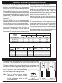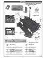
1
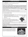
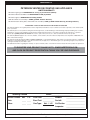
OWNER’S
MANUAL
In fireplaces with glass doors, this
log set may be used with the glass
doors open or closed.
Burner Systems:
GF-16/18-11(P)
GF-24-11(P)
GF-30-11(P)
FOR INSTALLATION IN
SOLID-FUEL BURNING
FIREPLACES*
Log Sets:
Charred Aged Split Oak
CHAS-(16/18, 24, 30)
Charred Frontier Oak
CHFR-(16/18, 24, 30)
DESIGN CERTIFIED
to
Vented Decorative Appliance
ANSI Z21.60b-2004
CSA 2.26b-2004
GF SERIES BURNER
WARNING
If the information in this manual is not
followed exactly, a fire or explosion may
result, causing property damage, personal
injury, or loss of life.
Do not store or use gasoline or other
flammable vapors and liquids in the vicinity
of this or any other appliance.
WHAT TO DO IF YOU SMELL GAS:
• Open a window.
• Do not try to light any appliance.
• Do not touch any electrical switch; do
not use any phone in the building.
• Immediately call the gas supplier
from a neighbor’s phone. Follow gas
supplier’s instructions.
• If you cannot reach the gas supplier,
call the fire department.
Installation and service must be performed
by a qualified professional installer, service
agency, or the gas supplier.
This appliance is only for use with the type of
gas indicated on the rating plate.
IMPORTANT: READ THESE INSTRUCTIONS
CAREFULLY BEFORE STARTING
INSTALLATION OF THE UNIT.
The Real-Fyre burner system is to be installed only in
a solid-fuel burning fireplace with a working flue and
constructed of noncombustible material.The installation,
including provisions for combustion and ventilation air
must conform with the National Fuel Gas Code, ANSI
Z223.1/NFPA 54, or the CSA B149.1, Natural Gas
and Propane Installation Code, and applicable local
building codes.
A damper clamp is included to maintain the minimum
permanent vent opening and to prevent full closure
of the damper blade. The chimney damper MUST
be fully opened when burning the unit. The unit is
designed to burn with yellow flames; thus adequate
ventilation is absolutely necessary.
To comply with certification, listings, and building
code acceptances, and for safe operation and proper
performance of this burner system, use ONLY Peterson
parts and accessories. Use of other controls, parts,
and accessories that are not designed for use with
Real-Fyre burner systems is prohibited and will void
all warranties, certifications, listings, and building code
approvals, and may cause property damage, personal
injury, or loss of life.
*Note: Solid-fuels shall not be burned in a fireplace
where a decorative appliance is installed.
INSTALLER:
Leave this manual with the appliance.
CONSUMER:
Retain this manual for future reference.
254-L-06-5
ROBERT H. PETERSON CO. 14724 East Proctor Ave., City of Industry, CA 91746
REV 6 - 1301300913
1
L-A2-159
MANUEL DU
PROPRIÉTAIRE
En cheminées avec les portes de
verre, cet ensemble de notation
peut être employé avec les portes
de verre ouvertes ou fermées.
Systèmes De Brûleur:
GF-16/18-11(P)
GF-24-11(P)
GF-30-11(P)
POUR L’INSTALLATION EN
CHEMINÉES BRÛLANTES DE
COMBUSTIBLE SOLIDE*
Ensembles De Notation :
Charred Aged Split Oak
CHAS-(16/18, 24, 30)
Charred Frontier Oak
CHFR-(16/18, 24, 30)
CONCEPTION CERTIFIÉE
à
Vented Decorative Appliance
ANSI Z21.60b-2004
CSA 2.26b-2004
BRÛLEUR DE SÉRIE DE GF
AVERTISSEMENT
Si l’infor mation en ce manuel n’est pas
suivie exactement, une incendie ou une
explosion peut résulter, entraînant des dégats
matériels, des blessures, ou la perte de la vie.
Ne stockez pas ou n’employez pas l’essence
ou d’autres vapeurs et liquides inflammables à
proximité de ceci ou d’aucun autre appareil.
CE QUI À FAIRE SI VOUS SENTEZ LE GAZ:
• Ouvrez une fenêtre.
• N’essayez pas de n’allumer aucun appareil.
• Ne touchez aucun commutateur électrique;
n’utilisez aucun téléphone dans le bâtiment.
• Appelez immédiatement le fournisseur
de gaz du téléphone du voisin. Suivez les
instructions du fournisseur de gaz.
• Si vous ne pouvez pas atteindre le
fournisseur de gaz, appelez le département
de feu.
L’installation et le service doivent être assurés par
un installateur qualifié et professionnel, l’agence de
service, ou le fournisseur de gaz.
Cet appareil sert seulement avec le type de gaz
indiqué de la plaque de contrôle.
INSTALLATEUR :
Laissez ce manuel avec l'appareil.
CONSOMMATEUR:
Maintenez ce manuel pour la future référence.
IMPORTANT: L I S E Z C E S I N S T RU C T I O N S
SOIGNEUSEMENT AVANT DE
COMMENCER L'INSTALLATION DE
L'UNITÉ.
Le Vrai-Fyre système de brûleur doit être installée
seulement dans une cheminée brûlante de combustible
solide avec une conduite de cheminée fonctionnante et être
construit avec du matériel non-combustible. L'installation,
y compris des dispositions pour l'air de combustion et de
ventilation doit se conformer au code national de gaz de
carburant, la norme ANSI Z223.1/NFPA 54, ou le CSA
B149.1, code d'installation de gaz naturel et de propane,
et codes du bâtiment locaux applicables.
Une bride plus humide est incluse pour maintenir l’ouverture
permanente minimum de passage et pour empêcher la
pleine fermeture de la lame plus humide. L'amortisseur
de cheminée DOIT être entièrement ouvert en brûlant
l'unité. L'unité est conçue pour brûler avec les
flammes jaunes; ainsi à ventilation proportionnée est
absolument nécessaire.
Pour se conformer à la certification, les listes, et les
acceptations de codes du bâtiment, et pour l'exploitation
sûre et l'exécution appropriée de ce système de brûleur,
utilisent SEULEMENT des pièces et des accessoires
de Peterson. L'utilisation d'autres commandes, pièces,
et accessoires qui ne sont pas conçus pour l'usage
avec de Real-Fyre systèmes de brûleur est interdite
et videra toutes les garanties, certifications, listes, et
approbations de codes du bâtiment, et peut causer des
dégats matériels, le dommage corporel, ou des pertes
humaines.
*Note: des Plein-carburants ne seront pas brûlés dans
une cheminée où un appareil décoratif est
installé.
254-L-06-5
ROBERT H. PETERSON CO. 14724 East Proctor Ave., City of Industry, CA 91746
REV 6 - 1301300913
2
L-A2-159
TABLE OF CONTENTS
GENERAL INFORMATION AND SPECIFICATIONS
DAMPER CLAMP INSTRUCTIONS
PARTS LIST
BURNER INSTALLATION
EMBER & LAVA ROCK PLACEMENT
LOG LIST
LOG PLACEMENT
LIGHTING INSTRUCTIONS - SERIES 11 VALVE
THERMAL RESET SWITCH - OPERATION
CLEANING AND SERVICING
FLAME DESCRIPTION
TROUBLESHOOTING
WARRANTY
REV 6 - 1301300913
3
4
4
5
6
7
7
8
11
12
13
13
14
16
L-A2-159
GENERAL INFORMATION AND SPECIFICATIONS
DO NOT USE the gas log set if any part has been
underwater. Immediately call a qualified service
technician to inspect the gas log set and to replace
any part of the control system and any gas control
which has been underwater.
the fireplace and away from the screen.
The gas log set must be isolated from the gas supply
piping system by closing its individual shut-off valve
during any pressure testing of the gas supply system
at test pressures equal to or less than 1/2 psig. The
gas log set and its individual shut-off valve must be
disconnected from the gas supply piping system when
testing at pressures in excess of 1/2 psig.
Peterson Real-Fyre® gas logs must be installed only
in a wood burning fireplace with the minimum venting
requirements met (see table on this page). Gas supply
pipe must be 1/2" minimum interior diameter. If the gas
line is longer than 20', a larger diameter line may be
necessary.
Keep the area of the gas log set clear and free from
combustible materials, gasoline, and other flammable
vapors and liquids.
DO NOT INSTALL the log set where completely
sealed doors are used. Doors must have a combined
air gap opening of no less than 18 square inches.
The minimum inlet gas supply pressure for purpose
of input adjustment is 5" for natural gas and 11" for
propane gas. Maximum inlet gas supply pressure for
this burner is 10.5" for natural and 13" propane gas.
A fireplace screen must be in place when the system
is burning. Provisions for adequate combustion air
must be maintained. Unless other provisions for
combustion air are provided, the screen shall have
an opening(s) for introduction of combustion air.
Combustion air is adequate when all flames curl into
The minimum firebox dimensions in which the log set
is certified to be installed, are listed in the table below.
Maintenance and service must be performed by the
gas supplier, or other qualified professional.
Minimum Fireplace Size
BTU Rating
Burner
Model
Width
Depth
Height
Natural Gas
Propane Gas
GF-16/18-11(P)
20"
15"
17"
35k
31k
GF-24-11(P)
27"
15"
17"
45k
41k
GF-30-11(P)
32"
15"
17"
55k
51k
Minimum permanent free opening area of chimney damper for venting
For factory-built fireplaces
For masonry-built fireplaces
Chimney
height
16/18"
24"
30"
16/18"
24"
30"
15'
22 sq. in.
28 sq. in.
34 sq. in.
26 sq. in.
32 sq. in.
38 sq. in.
20'
20 sq. in.
25 sq. in.
31 sq. in.
24 sq. in.
29 sq. in.
35 sq. in.
30'
18 sq. in.
23 sq. in.
28 sq. in.
22 sq. in.
27 sq. in.
32 sq. in.
Note: The minimum chimney height from hearth to top of chimney is 15'.
DAMPER CLAMP INSTRUCTIONS
The damper clamp with hex bolt (Fig. 4-1) is provided as a means to prevent
full closure of the damper blade. The clamp is easily attached to most
damper blades with pliers or a wrench, and must be permanently installed.
The clamp is designed to prevent accidental closure of the damper when
installed as illustrated (Fig. 4-2 and Fig. 4-3). Should the clamp not fit, or
fail to provide the permanent vent opening listed in the table found above,
have a permanent stop installed, remove the
damper blade, or have the damper cut to provide Set screw
the minimum permanent opening required.
Note: These are minimum damper opening
specifications. The damper must be
completely opened when operating
this gas appliance to achieve the best
ventilation possible.
REV 6 - 1301300913
Damper clamp
Fig. 4-1
4
Open
Closed
Fig. 4-2
Fig. 4-3
L-A2-159
PARTS LIST
Replacement parts can be ordered from
your local Real Fyre® dealer.
2
12
13
14
10
8
24" Model Shown
9
3
5
ON/OFF/PILOT
control
4
1
6
5
11
7
Note: Photos not to scale
ITEM
NO.
ITEM
NO.
DESCRIPTION
DESCRIPTION
1.
Control valve
8.
Piezo ignitor button
2.
Thermal reset switch
9.
Remote receiver
3.
Pilot assembly
10.
Remote
4.
Base assembly with burner and grate
11.
Damper clamp
5.
Access doors (2)
12.
Glowing embers
6.
Gas fitting (flare)
13.
Lava rocks
7.
Connector kit
14.
Bryte CoalsTM
REV 6 - 1301300913
5
L-A2-159
BURNER INSTALLATION
WARNING: Failure to position the parts in accordance with these diagrams or failure to use only
parts specifically approved with this appliance may result in property damage or personal
injury.
Setting the thermal reset switch bracket into its operating position
This GF series burner comes equipped with a thermal reset switch located at the rear of the unit. To avoid
damage during delivery, the switch is packed horizontally with one screw securing it into place (see Fig. 6-1).
The thermal switch bracket must be moved to the vertical position before the burner system is installed in
the fireplace. To accomplish this, remove the screw attached to the back of the burner assembly (see Fig.
6-2). Rotate the bracket around the rivet until it is vertical and the bracket hole lines up with the empty
screw hole. Insert the screw into the holes and tighten it down with a screwdriver to lock the bracket in the
vertical position (see Fig. 6-3).
screw
hole
screw
removed
rivet
Fig. 6-1
Fig. 6-2
Fig. 6-3
Reference the THERMAL SWITCH OPERATION section.
The Peterson Real-Fyre® gas log set must be installed by a qualified professional technician. Instructions
must be followed carefully to ensure proper performance and full benefit from the gas log set.
1. Remove all items from the carton and check
the PARTS LIST on the previous page to be
sure all parts are included.
Fig. 6-4
2. Shut off the gas to the fireplace.
3. Place the burner assembly into the fireplace so
that the controls face the room.
4. Remove the cap from the gas stub.
5. Connect the large flare fitting on the flex
connector to the gas stub. If Teflon tape or pipe
compound is applied to the gas stub, use a
compound that is resistant to all gasses.
6. Attach the flex connector kit to the adapter on
the valve and tighten (Fig. 6-4).
Attach flex connector kit to
gas fitting flare adapter
7. Turn on the gas to the fireplace and test for leaks
with a soapy water solution. (Never use open
flame for testing.) If a leak is found, tighten
the adapter until no leaks are detected.
REV 6 - 1301300913
6
L-A2-159
EMBER & LAVA ROCK PLACEMENT
EMBER PLACEMENT
Sprinkle the glowing embers (see PARTS LIST) lightly and evenly
over the entire surface of the ember burner screen. Break up any
clumps that may have developed during shipment. Bryte CoalsTM
should be placed over the glowing embers, also spread out evenly (Fig.
7-1). Failure to follow these instructions will result in unsafe operation.
Fig. 7-1
Ember burner pan
Platinum
Embers
Important: Do not add any additional embers or Bryte CoalsTM
to this log set. Any additional embers may cause
unsafe operation.
Lava rocks OK
LAVA ROCKS (DECORATIVE)
Spread the lava rocks (see PARTS LIST) on the bottom of the fireplace, around (but NOT on) the upper
burner pan.
Note: It is OK to allow lava rocks onto the portion of the burner that is resting directly on the fireplace
floor, as long as they do not interfere with the controls.
IMPORTANT
For all valves, the air MUST be purged from the gas line before the pilot will light and burn properly. The time
needed to purge will depend on the length of the gas line to the unit and the amount of time since the unit or
gas line was last used. It may take several minutes before all the air is purged and the pilot will light and burn
properly. Reference the LIGHTING INSTRUCTIONS section in this manual.
LOG LIST
5
16/18" Log Sets
4
(CHFR-16/18 shown)
ITEM
NO.
3
DESCRIPTION
1.
Front bottom log
2.
Rear bottom log
3.
Left middle log
4.
Right middle log
5.
Top center log
2
1
24" & 30" Log Sets
6
ITEM
NO.
5
7
(CHFR-24 shown)
DESCRIPTION
1.
Front bottom log
2.
Rear bottom log
3.
Left middle log
4.
Right middle log
5.
Left top log
6.
Right top log
7.
Top center log
2
3
1
Note:
N
t
REV 6 - 1301300913
4
7
The llog sett iis packed
Th
k d separately.
t l
L-A2-159
LOG PLACEMENT
Proper log placement is important to ensure proper performance of the gas burner system.
Be sure to follow the log placement instructions carefully, referring to the
figures where appropriate.
16/18" LOG SETS
PLACEMENT OF BOTTOM LOGS
1. Place the rear bottom log (#2) on the back of the grate and center it side to side. Be sure that the notches
in the bottom of the log rest securely over the grate fingers. There must be a clearance between the rear
log and the pilot assembly located on the right side of the burner. See Fig. 8-1 and 8-2. Place the front
bottom log (#1) on the front part of the grate and center it side to side. Be sure that the notches in the
bottom and front of the log rest securely over the grate fingers. See Fig. 8-2.
Fig. 8-2
Ensure clearance
between rear
log and pilot
assembly
Fig. 8-1
PLACEMENT OF MIDDLE AND TOP LOGS
2. Place the middle logs (#3 and #4) so that they
rest on the bottom logs as shown in Fig. 8-3.
Be sure that the middle logs rest securely over
the grooves and notches located on the bottom
logs.
3. Complete log placement by securing the top
center log (#7) over the grooves and notches
located on the middle logs (see Fig. 8-4).
Fig. 8-3
Fig. 8-4
CAUTION: BURN HAZARD! Logs will remain hot for some time after use. You must maintain the log
layout as shown to ensure proper operation of your log set. If you need to reposition any
log to maintain the proper layout, use heat-resistant gloves or allow logs adequate time to
cool before handling.
REV 6 - 1301300913
8
L-A2-159
LOG PLACEMENT (cont.)
24" AND 30" LOG SETS
1. Place the rear bottom log (#2) on the back of the grate and center it side to side. Be sure that the notches
in the bottom of the log rest securely over the grate fingers. There must be a clearance between the rear
log and the pilot assembly located on the right side of the burner. See Fig. 9-1 and 9-2. Place the front
bottom log (#1) on the front part of the grate and center it side to side. Be sure that the notches in the
bottom and front of the log rest securely over the grate fingers. See Fig. 9-2.
Fig. 9-2
Ensure clearance
between rear
log and pilot
assembly
Fig. 9-1
PLACEMENT OF MIDDLE AND TOP LOGS
2. Place the middle logs (#3 and #4) so that they
rest on the bottom logs as shown in Fig. 9-3.
Be sure that the middle logs rest securely over
the grooves and notches located on the bottom
logs.
3. Place the left and right top logs (#5 and #6) so
that they rest on the bottom logs as shown in Fig.
9-4. Be sure that the top logs rest securely over
the grooves and notches located on the bottom
logs. Complete log placement by securing the
top center log (#7) over the grooves and notches
located on the middle logs.
Fig. 9-3
REV 6 - 1301300913
Fig. 9-4
9
L-A2-159
INSTRUCTIONS D’ÉCLAIRAGE - VALVE DE LA SÉRIE 11
POUR VOTRE SÛRETÉ, LISEZ AVANT DE S’ALLUMER
AVERTISSEMENT : Si vous ne suivez pas ces instructions exactement, une incendie ou une
explosion peut résulter entraînant des dégats matériels, des blessures ou la perte de la vie.
N’employez pas cet appareil si n’importe quelle partie a été sous-marine. Réclamez immédiatement un technicien
de service professionnel qualifié et pour inspecter l’appareil et pour remplacer n’importe quelle partie du système de
commande et de n’importe quelle commande de gaz qui a été sous l’eau.
Le
systèmede
debrûleur
brûleuraaun
unpilote
pilotequi
quipeut
peutêtre
êtreallumé
alluméàen
employant
construit
le passage
sur lelebrûleur,
Le Vrai-Fyre®
Vrai-Fyre système
la main
en utilisant
unedans
allumette
ou un d’ignitor
allumeur.deEnpiezo
allumant
pilote,
ou
employer
à la main une
allumette ou désirer ardemment allumeur étranglé. En allumant le pilote, suivez ces instructions exactement.
suivez
ces instructions
exactement.
AVANT DE S’ALLUMER, sentez tous autour du secteur de brûleur pour le gaz. Soyez sûr de sentir à côté du plancher car un certain gaz
est plus lourd que l’air et arrangerez sur le plancher. SI VOUS SENTEZ LE GAZ, SUIVEZ LES INSTRUCTIONS À LA P. 1.
Utilisez seulement votre main pour enfoncer ou pour tourner le bouton de commande de gaz. N’utilisez jamais les outils. Si le bouton
n’enfoncera pas ou ne tournera pas à la main, n’essayez pas de le réparer. Appelez un technicien de service professionnel qualifié et. La
force ou la réparation essayée peut avoir comme conséquence l’incendie ou l’explosion.
AJUSTANT LE PILOTE
1. La flamme pilote devrait encercler le bout de générateur,
et est préréglée à l’usine (Fig. 10-2).
ALLUMANT LE PILOTE
Pour lire le bouton de commande de soupape de sûreté (Fig.
10-1) lisez l’indicateur formé par larme la plus proche en
métal d’inscription.
2. Si l’ajustement est nécessaire, (Fig. 10-1) tournez la vis
d’approche de gaz dans le sens contraire des aiguilles
pour augmenter la flamme pilote, ou
d’une montre
pour diminuer dans le sens des aiguilles d’une montre
la flamme pilote.
1. Si le bouton de commande de soupape de sûreté est
en position PILOT, enfoncez légèrement sur le bouton
et tournez-le dans le sens des aiguilles d’une montre
jusqu à la position de OFF.
ENTRETIEN
Votre brûleur à casserole est équipé d’un pilote de sûreté qui
coupera l’offre de gaz au cas où le pilote serait ne brûlant pas
ou ne fonctionnant pas correctement. Assurez-vous que le
pilote est ajusté correctement et que les agrafes de cosse de
générateur sont étroitement reliées aux vis terminales sur la
valve. Si le pilote ne restera pas allumait, appelle votre utilité
de gaz ou fournisseur locale de gaz.
2. Libérez le bouton et attendez cinq minutes.
3. Tournez le bouton de soupape de sûreté dans le sens
à la position
contraire des aiguilles d’une montre
PILOT (seulement le gaz pilote coulera quand le bouton
est enfoncé).
4. Placez
Po u s s une
e z elongue
t t e n eallumette
z l e b oou
u t oun
n allumeur
d e s o u de
p a butane
pe de
au
brûleur
pilote et en même
temps,
poussentlelebouton
bouton
sûreté
entièrement
dedans
et enfoncez
de
soupape
sûreté
entièrement
dedans. Le
pilote
d’ignitor
de de
piezo
plusieurs
fois jusqu’aux
lampes
s’allumera.
témoin.
5. Tenez le bouton de soupape de sûreté dedans pendant
approximativement 60 secondes avant de libérer.
Un contrôle périodique du suivant devrait être exécuté au
moins annuellement par un représentant qualifié de service
professionnel.
1.
distance pour
l’opération
1. Valves
Valves et
et récepteur
commande àd’interrupteur
à levier
pour
appropriée.
l’opération appropriée.
6. Si le pilote ne reste pas s’allumait, la position de
OFF de bouton de soupape de sûreté dans le sens des
entièrement. Attendez cinq
aiguilles d’une montre
minutes, puis répétez les étapes 3. à 5.
Système de
de conduite
conduite de
de cheminée pour la rouille,
2. Système
2.
rouille, les
les
dommages ou
dommages,
ou les
les fuites.
fuites.
3. Une
Uneopération
opération plus
plus humide.
humide.
3.
ALLUMAGE
BRÛLEUR
PRINCIPAL
METTANT ÀDU
FEU
LE BRÛLEUR
PRINCIPAL
4. Orifices pour la saleté ou d’autres corps étrangers.
Avec le pilote a allumé, tourne le bouton de soupape de sûreté 4. Orifices pour la saleté ou d’autres corps étrangers.
Avec lampe témoin, tournent le bouton de soupape de sûreté
5. Contrôle visuel sur le brûleur.
dans
contraire
desdes
aiguilles
d’uned’une
montre
à la
aiguilles
montreà la position
danslelesens
sens
contraire
5. Contrôle visuel sur le brûleur.
de
fonctionnement.
Commutez
récepteurd’interrupteur
à distance à àla
position
de ON. Commutez
la le
commande
position
Référez-vous En plus de ces instructions, lisez et suivez les instructions
levier àde
la fonctionnement,
position de ON et
et le
lebrûleur
brûleurs’allumera.
s’allumera.
Si cette unité était embarquée avec un extérieur, ou si un
à la LISTE DE PIÈCES pour l’endroit à distance de récepteur.
à
distanceà séparées
d’actionner
le brûleur
à distance.
système
distance était
installé plus
tard, lisez
et suivez
COUPANT LE BRÛLEUR PRINCIPAL
ARRÊT DU BRÛLEUR PRINCIPAL
les instructions à distance séparées d’actionner le brûleur
la récepteur
commande
à levier àdelarepos.
position
Commutezle
Commutez
à d’interrupteur
distance à la position
Le à distance.
de OFF.
Le pilote
pilote
restera
sur. restera s’est allumé.
ARRÊT
DU LE
PILOTE
COUPANT
PILOTE
Soyez sûr
sûr que commande
à levier
et
Soyez
le récepteurd’interrupteur
à distance est
éteintest
etéteint
enfonce
de soupape
sûreté
dansdes
le
enfonce
et
tourne et
le tourne
boutonledebouton
soupape
de sûretéde
dans
le sens
à
la
position
de
OFF.
sens
des
aiguilles
d’une
montre
aiguilles d’une montre
à la position de repos.
INTERRUPTEUR
INTERRUPTEURÀÀLEVIERINTERRUPTEUR
LEVIERINTERRUPTEURÀÀLEVIER
LEVIER
Fig.
Fig. 10-1
10-1
Fig. 10-2
Generator
HARNAIS DE
HARNAIS
PORT
PILOTE
DEDE
GAZ
CÂBLAGEDE
PORT
PILOTE
GAZ
CÂBLAGE
Pilot screw
Pilot
VIS PILOTE
VIS PILOTE
DE gas
CAP
port
Pilot
Safety
valve
control
knob
Electrode
IN
IN
OUT
OUT
TP
TH TH
TP
TH TH
TP
TP
Fig. 10-1
IN
IN
À L’EXTÉRIEUR
(si c’est approprié)
BOUTON
BOUTON DE
DE
COMMANDE
COMMANDE
Note: La flamme pilote devrait encercler le dessus
du générateur
DE
DE VALVE
VALVE DE
DE
SAFTEY
SAFTEY
10
LIGHTING INSTRUCTIONS - SERIES 11 VALVE
FOR YOUR SAFETY, READ BEFORE LIGHTING
WARNING
If you do not follow these instructions exactly, a fire or explosion may result, causing property
damage, personal injury, or loss of life.
Do not use this appliance if any part has been underwater. Immediately call for a qualified professional service technician
to inspect the appliance and to replace any part of the control system and any gas control that has been underwater.
The
built-in
piezoorignitor
switch
onlighting
the burner,
or byfollow
hand
The Real-Fyre
Real-Fyre®® burner
burner system
system has
has aa pilot
pilotthat
thatcan
canbe
belitlitbybyusing
handthe
using
a match
lighter.
When
the pilot,
using
a
match
or
long-necked
lighter.
When
lighting
the
pilot,
follow
these
instructions
exactly.
these instructions exactly.
BEFORE LIGHTING, smell all around the burner area for gas. Be sure to smell next to the floor, as some gas is heavier than
air and will settle on the floor. IF YOU SMELL GAS, FOLLOW THE INSTRUCTIONS ON P. 1.
Use only your hand to push in or turn the gas control knob. Never use tools. If the knob will not push in or turn by hand, don't
try to repair it. Call a qualified professional service technician. Force or attempted repair may result in fire or explosion.
LIGHTING THE PILOT
ADJUSTING THE PILOT
To read the safety valve control knob (Fig. 11-1),
read the marking nearest the teardrop-shaped metal
pointer.
1. If the safety valve control knob is in the PILOT
position, push in slightly on the knob and rotate it
to the OFF position.
clockwise
2. Release knob and wait five (5) minutes.
3. Turn safety valve knob counterclockwise
to the
PILOT position. (Only the pilot gas will flow when
the knob is pushed in.)
4. Place
a long
match
or a butane
at the
Push and
hold
the safety
valve lighter
knob fully
in pilot
and
burner,
the same
push
the safety
push in and
the at
piezo
ignitortime,
button
several
timesvalve
until
knob
fullylights.
in. The pilot will light.
the pilot
5. Hold the safety valve knob in for approximately 60
seconds before releasing.
6. If the pilot does not stay lit, turn the safety valve
to the full OFF position. Wait five
knob clockwise
(5) minutes, then repeat steps 3 through 5.
IGNITING
IGNITING THE
THE MAIN
MAIN BURNER
BURNER
a. The pilot flame should encircle the generator tip,
and is preset at the factory (Fig. 11-2).
b. If adjustment is necessary (Fig.11-1), turn the gas
to increase
adjustment screw counterclockwise
to decrease the
the pilot flame, or clockwise
pilot flame.
MAINTENANCE
Your pan burner is equipped with a safety pilot that will
shut off the gas supply in the event that the pilot is not
functioning properly. Make sure the pilot is adjusted
properly and that the generator spade clips are tightly
connected to the terminal screws on the valve. If the
pilot will not stay lit, call your local gas utility or gas
supplier.
A periodic check of the following should be performed
at least annually by a qualified professional service
representative:
1.
remote
receiver
proper operation.
1. Valves
Valvesand
and
toggle
switchforcontrol
for proper
operation.
2. Flue system for rust, damage, or leaks.
With
Withthe
thepilot
pilot lit, turn the safety valve knob counterclockwise
to
to the
to the
theON
ONposition.
position.Switch
Switchthe
theremote
toggle receiver
switch control
ON
position,
and theand
burner
light.
Refer
the PARTS
to the
ON position,
the will
burner
will
light.toRefer
to the
the remote
location.
LIST
for LIST
for thereceiver
toggle switch
location.
PARTS
2.
3.
3.
4.
Flue system
for rust, damage, or leaks.
Damper
operation.
Damper
operation.
Orifi
ces for
dirt or other foreign matter.
4. Visual
Orifices
for dirt
foreign matter.
5.
check
on or
theother
burner.
5. Visual check on the burner.
In addition to these instructions, read and follow the
SHUTTING
SHUTTING OFF
OFF THE
THE MAIN
MAIN BURNER
BURNER
separate
instructions
operate
burner
If this unitremote
was shipped
with a to
remote,
or ifthe
a remote
Switch
receiver
to thetoOFF
position.
The pilot
Switch the
the remote
toggle switch
control
the OFF
position.
The remotely.
system was installed later, read and follow the
will
lit. lit.
pilotremain
will remain
separate remote instructions to operate the burner
remotely.
SHUTTING OFF THE PILOT
SHUTTING OFF THE PILOT
Be
receiver
is OFF
and and
depress
and
Be sure
sure the remote
toggle switch
control
is OFF
depress
toto the
turn
the the
safety
valve
knob
clockwise
the OFF
and turn
safety
valve
knob
clockwise
position.
position.
Toggle
switch
Toggle
switch
Generator
Wiring harness
Wiring harness
Pilot screw
Pilot gas
Pilot gas
Pilot
screw
Pilot
screw
port Pilot
portgas port
To remote
(if applicable)
Electrode
Safety
Safety Safety
valve
valve valve
control control
control
knob knob
knob
IN
IN
IN
IN
OUT
OUT
OUT
TH TH
TP
TH TH
TP
TP
THTP
TH
TP
TP
IN
IN
Pilot
Note: Pilot flame should encircle top of the generator.
Fig. 11-2 Lighting the pilot
Fig. 11-1
11
THERMAL RESET SWITCH - OPERATION
This gas log set is equipped with a safety thermal reset switch, located at the rear left of the burner
(see Fig. 12-1). If the chimney will not properly vent, or is blocked when the burner is in operation,
the system will shut down. The pilot will remain lit. Call a qualified technician to check the unit. Have
the chimney cleaned and inspected to ensure proper venting.
TO RESET THE THERMAL SWITCH
1. Wait for the fireplace temperature to cool down before opening the glass doors.
2. Turn the remote receiver on the left side of the burner to OFF. Turn the control knob on the front
right of the burner to OFF.
3. Ensure the damper is fully open.
CAUTION: LOG SET MAY BE HOT - AVOID TOUCHING LOGS OR BURNER PARTS.
4. Carefully reach to the underside of the thermal switch and press it up (see Fig. 12-1). A click
may be heard.
5. Relight the pilot per the LIGHTING INSTRUCTIONS section.
If the problem persists remove the damper completely.
If the problem still continues, contact the local dealer.
CAUTION: THE DAMPER MUST BE FULLY OPEN WHEN BURNING THE LOG SET.
Thermal reset switch located
at rear of gas burner
Fig. 12-1
CAUTION: Before resetting, ensure
nsure
control knob is in the
e OFF
position.
To reset, press button up
12
CLEANING AND SERVICING
Note: Regular cleaning and servicing will be necessary to ensure proper pilot operation and proper burn
characteristics.
Always shut off the gas to the appliance while performing service work.
Allow the appliance to cool before servicing.
Installation, service, and repair must be done by an NFI Certified or other qualified professional
service technician. The appliance MUST be inspected before use, and cleaned at least annually
to prevent burner shutdown, sooting, odors, etc. by a qualified professional service technician. It
must be checked for clean burning operation and proper pilot appearance, with the correct tools to
service this unit. More frequent cleaning may be required. Excessive lint can build up on this unit from
carpeting, bedding material, pet hairs, or other particles in the air. It is imperative that all control components
and compartments, burner(s), air shutters, and circulating air passageways of the appliance be kept clean
and free of all obstructions.
In addition, a periodic examination and cleaning (anually) of the venting system and the solid-fuel-burning
fireplace should be conducted by a qualified professional service technician.
Any safety screen or guard removed for servicing must be replaced prior to operating this appliance.
TO CLEAN THE BURNER SYSTEM
1. Remove the log set and embers. Use a vacuum cleaner to remove loose particles from all surfaces of
the burner log set. Do not use cleaning fluids.
2. Dust the grate, the assembly, and the burners. Using a compressed
air duster (commonly available at computer, electronic, or office
supply stores); blow through all of the burner ports, and the pilot
assembly area.
Fig. 13-1
Burner ports
3. Replace batteries as needed.
4. Reinstall the log set and embers as instructed in this manual.
If, after a period of use, the flames start to exhibit unusual shapes and
behavior, or the burners fail to ignite smoothly, the burner ports may
require some cleaning. If this happens, it is preferable to contact the
nearest dealer to get the appliance serviced.
Pilot
Do not remove the rating plates or the warning tags. These are an integral safety and identification
component of this appliance.
We recommend following these instructions at the beginning of each fireplace season and as needed
throughout the year, depending on your usage pattern and the environmental conditions in your
home. More frequent cleaning and maintenance may be necessary when burning propane gas than
with natural gas.
FLAME DESCRIPTION
Observe the flames. The main burner flames should be blue
at the base and a combination of blue/yellow at the body and
at the tips. They should be approximately 5-8" above the logs,
with the center flame being the tallest. The ember flames
should be 1/4" to 5" above the embers(See 13-2 for example.)
Fig. 13-2 Flame appearance
13
TROUBLESHOOTING
POSSIBLE CAUSE
1
SOLUTIONS
BURNER SHUTTING DOWN DURING OPERATION
A. Insufficient or excessive gas
pressure
A1. Check gas pressure (check with local gas company).
B. Log placement
B. Reference the LOG PLACEMENT section in this manual for recommended
log positioning.
C. Flue area, fireplace, or
damper dirty from soot
C. Clean around, above, and under damper thoroughly. Clean fireplace, removing
loose material, including soot and creosote.
D. Fireplace too small for unit
D. Ensure minimum requirements are met. (See FIREPLACE SIZE
REQUIREMENT section in this owner’s manual.)
E. P i l o t f l a m e l i f t i n g o f f
thermocouple/generator
E. Check gas pressure (see section A1).
F. Pilot (remote compatible)
F. Contact your dealer for instructions on replacement.
A2. Other gas appliances may be on the same gas line, dropping gas pressure
to log set. Check pressures with everything operating to ensure adequate
pressure.
G. Closed
Blockages
on burner
G. Vacuum
lava granules
or the
material
that chimney
may havecleaned.
fallen onto
burner
pipe
G.
damper
or blocked flue G.
Open theany
damper
and have
flue and
Reset
safety
area. switch (see THERMAL RESET SWITCH section).
thermal
2
PILOT WILL NOT LIGHT
A. P i l o t f l a m e l i f t i n g o f f
thermocouple/generator
A. Check gas pressure (check with local gas company).
B. Electronic spark not lighting
pilot
B. Check to assure sparking when activated.
C. Ignitor electrode wire loose
C. Check wiring and reconnect any loose wiring.
D. Gas supply off/manual
shutoff valve closed
D. Turn on gas supply or open manual shutoff valve.
E. Air in gas line
E. Bleed the gas supply line and repeat LIGHTING INSTRUCTIONS until air is
removed.
F. Pilot hood blocked
F. Check for debris or dirt / Clean pilot
G. Dead batteries (electronic
pilots only)
G. Replace batteries as needed.
3
Note: You may need to turn or press ignitor several times to ignite pilot. See
LIGHTING INSTRUCTIONS for your control valve.
LOW FLAME HEIGHT
A. Gas pressure
A. Check gas pressure (check with local gas company).
B. Propane tank running low
B. Fill tank completely.
4
BURNER NOT BURNING EVENLY
A. Burner orifice clogged
A. Clean burner orifice.
B. Top burner lights; bottom
burner has delayed ignition.
B1. Check gas pressure. Can be caused by too small of a gas line (See ANSI
223.1/NFPA 54 Piping Guidelines).
B2. Low propane tank level. Vacuum burner tube for soot blockage and fill propane
tank.
5
ODORS
A. Gas leak
A. Shut off gas, if possible. Follow instructions on front page. Have a qualified
professional installer or the gas company correct all leaks.
B. New home, new carpet, or
new paint
B. When these odors are drawn into the fireplace, this may cause objectionable
odors. Thoroughly ventilate the area before restarting your log set.
14
TROUBLESHOOTING (Cont.)
POSSIBLE CAUSE
SOLUTIONS
SOOTING
6
A. On logs, in firebox, or room
A. Check gas pressure (check with local gas company).
B. Drafts in room
B. Eliminate drafts by closing heating and air conditioning
vents, returns, and outside air vents. Fans blowing directly
into fireplace should be turned off when set is operating.
C. Air shutters blocked (if applicable)
C. Air shutters are blocked with debris. Vacuum debris away
from air shutter.
D. Log placement
D. See solution in troubleshooting 1B.
E. Using natural-gas burner on propane gas or
propane burner on natural gas
E. If the gas listed on the nameplate does not match the gas
you are burning, shut down the burner system immediately
and completely (including pilot) following the steps in
the LIGHTING INSTRUCTIONS section. Then call your
dealer.
F. Adding any accessories to log sets
F. Shut down log set and take off any logs or accessories that
do not belong with the set.
7
PILOT WILL NOT STAY LIT
A. Valve won’t hold
A. Contact your dealer for instructions on replacement.
B. Pilot hood not aimed at thermocouple
B. Pilot hood bent; replace pilot or angle pilot hood properly so
pilot flame hits thermocouple.
C. Pilot line bent
C. Replace pilot line.
D. Thermocouple is loose
D. Tighten thermocouple nut at gas control valve.
E. Thermocouple cracked or worn out
E. Replace thermocouple.
F. Excessive down draft
F. Install chimney cap / Outside chimney too close to other
peaks / Check chimney flue for proper height / Poorly
designed chimney
15
WARRANTY
PETERSON VENTED DECORATIVE GAS APPLIANCE
LIMITED WARRANTY
All Peterson gas logs are WARRANTED for as long as you own them (lifetime).
All Peterson burner assemblies are WARRANTED for TEN (10) YEARS.
All Peterson glass is WARRANTED for FIVE (5) YEARS.
SPK-26 controls are covered by a THREE (3) YEAR “All Parts” Warranty.
All other Peterson valves, pilots, and controls are covered by a ONE (1) YEAR Limited Warranty (excluding batteries).
PLEASE KEEP A COPY OF YOUR SALES SLIP FOR PROOF OF PURCHASE
This warranty applies to the original purchaser and to single family residential use only. It commences from date of purchase, and is valid only with
proof of purchase.
This warranty does not cover parts becoming defective through misuse, accidental damage, electrical damage, improper handling, lack of routine
maintenance, storage, and/or installation. Product must be installed (and gas must be connected) as specified in the instructions or operator’s
manual, by a qualified professional installer. Accessories, parts, valves, remotes, etc., when used must be Peterson Co. product.
This warranty does not apply to rust, corrosion, oxidation, or discoloration, unless the affected component becomes inoperable. It does not cover
labor or labor-related charges.
This warranty specifically excludes liability for indirect, incidental, or consequential damages. Some states do not allow the exclusion or limitation of
incidental or consequential damages, so the above exclusion may not apply to you. This warranty gives you specified legal rights, and you may have
other rights that may vary from state to state.
For additional information regarding this warranty, or to place a warranty claim, contact the R.H. Peterson dealer where the product was purchased.
TO REGISTER YOUR PRODUCT ONLINE GO TO: WWW.RHPETERSON.COM,
AND CLICK ON PRODUCT REGISTRATION. THANK YOU FOR YOUR PURCHASE.
Quality Check
Burner Orifices Nat.
Date:_________________
L.P.
Leak Test: ___________ Model#:
___________________
Main:
____ ____
Burn Test: ___________ Serial#:
___________________
Other:
____ ____
Gas Type:
Nat. / L.P.
Air Shutter: ___________________
Inspector:
___________________
Robert H. Peterson Co. • 14724 East Proctor Avenue • City of Industry, CA 91746
16