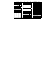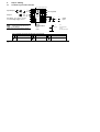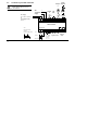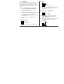
1
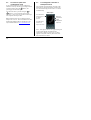
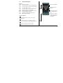
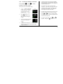
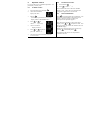
ENG User Guide PID Temperature controllers 3200 E U ROT H E R M This booklet includes: User Guide (HA028582ENG Issue 3) Manuel Utilisateur (HA028582FRA Indice 2) Bedienungsanleitung (HA028582GER Ausgabe 3) 3200 Series PID Temperature Controllers Applies to Model numbers 3216, 3208, 32h8 and 3204 Contents 1. What Instrument Do I Have? ............................................................................ 4 1.1 1.2 1.3 1.3.1 1.3.2 1.3.3 1.3.4 1.4 2. Unpacking Your Controller .................................................................................................4 Dimensions .........................................................................................................................5 Step 1: Installation.............................................................................................................7 Panel Mounting the Controller ............................................................................................................................... 7 Panel Cut-out Sizes ..................................................................................................................................................... 7 Recommended minimum spacing of controllers. Applies to all Model sizes.......................................... 8 To Remove the Controller from its Sleeve.......................................................................................................... 8 Ordering Code ....................................................................................................................9 Step 2: Wiring.................................................................................................10 2.1 Terminal Layout 3216 Controller .......................................................................................10 Terminal Layout 3208 and 3204 Controllers.......................................................................11 2.3 Terminal Layout 32h8 Controller.......................................................................................12 Wire Sizes .........................................................................................................................13 Sensor Input (Measuring Input) ........................................................................................13 Input/Output 1 & Output 2 ...............................................................................................14 2.2 2.4 2.5 2.6 Part number HA028582ENG. Issue 3.0, Oct-05. Applies to software versions 2.07 and 2.27 T 1 2.7 2.8 2.9 2.10 2.11 2.12 2.13 2.14 3. Safety and EMC Information............................................................................20 3.1 4. Installation Safety Requirements ...................................................................................... 21 Switch On ........................................................................................................25 4.1 4.2 4.3 4.4 4.4.1 4.4.2 4.4.3 4.4.4 4.4.5 2 Output 3........................................................................................................................... 15 Output 4 (AA Relay) ......................................................................................................... 15 Digital Inputs A & B.......................................................................................................... 16 Current Transformer ........................................................................................................ 17 Transmitter Power Supply ................................................................................................ 17 Digital Communications ................................................................................................... 18 Controller Power Supply................................................................................................... 19 Example Wiring Diagram .................................................................................................. 19 Initial Configuration ......................................................................................................... 25 To Re-Enter Quick Code configuration mode .................................................................... 28 Pre-Configured Controller or Subsequent Starts ............................................................... 28 Front panel layout............................................................................................................ 29 To Set The Target Temperature (setpoint) ....................................................................................................... 30 Alarm Indication ........................................................................................................................................................ 30 Auto, Manual and Off Mode ................................................................................................................................. 30 To Select Auto, Manual or OFF Mode ................................................................................................................ 31 Operator Parameters in Level 1............................................................................................................................ 32 5. Operator Level 2..............................................................................................33 5.1 5.2 5.3 5.4 5.5 5.6 5.7 5.8 5.8.1 5.8.2 5.8.3 To Enter Level 2 ................................................................................................................33 To Return to Level 1 .........................................................................................................33 Level 2 Parameters............................................................................................................33 Timer Operation ...............................................................................................................42 Dwell Timer ......................................................................................................................43 Delayed Timer ..................................................................................................................44 Soft Start Timer ................................................................................................................45 Programmer......................................................................................................................46 Programmer Servo Mode and Power Cycling................................................................................................... 47 To Operate the Programmer ................................................................................................................................. 48 To Configure the Programmer.............................................................................................................................. 49 3 Installation and Basic Operation 1. What Instrument Do I Have? Thank you for choosing this 3200 series Temperature Controller/Programmer. The 3200 series provide precise temperature control of industrial processes and is available in three standard DIN sizes:• 1/16 DIN Model Number 3216 • 1/8 DIN Model Number 3208 • 1/8 DIN Horizontal Model Number 32h8 • 1/4 DIN Model Number 3204 A universal input accepts various thermocouples, RTDs or process inputs. Up to three (3216) or four (3208, 32h8 and 3204) outputs can be configured for control, alarm or re-transmission purposes. Digital communications and a current transformer input are available as options. The controller may have been ordered to a hardware code only or pre-configured using an optional ‘Quick Start’ code. The label fitted to the side of the sleeve shows the ordering code that the controller was supplied to. The last two sets of five digits show the Quick Code. If the Quick Code shows *****/***** 4 the controller will need to be configured when it is first switched on. This User Guide takes you through step by step instructions to help you to install, wire, configure and use the controller. For features not covered in this User Guide, a detailed Engineering Manual, Part No HA027986, and other related handbooks can be downloaded from www.eurotherm.co.uk. 1.1 Unpacking Your Controller The following items are included in the box: • Controller mounted in its sleeve • Two panel retaining clips • AN IP65 sealing gasket mounted on the sleeve • Component packet containing a snubber for each relay output and a 2.49Ω resistor for current inputs (see section 2) • This User Guide 1.2 Dimensions The following two pages show general views of the controllers together with overall dimensions. 3216 Top View 3216 Front View 3216 Side View 1.25mm (0.5in) 90mm (3.54in) 48mm (1.89in) Latching ears Panel retaining clip 48mm (1.89in) IP65 Sealing Gasket Panel retaining clips 5 32h8 Front 3208 Front 3204 Front 48mm (1.89in) 96mm (3.78in) 1 96mm (3.78in) 96mm (3.78in) 1 1 48mm (1.89in) 96mm (3.78in) 32h8 Side with Panel Retaining Clips 90mm (3.54in) 3 2 1.25mm (0.5in) 3208 Top with Panel Retaining Clip 6 90mm (3.54in) 1 Latching ears 2 Panel Retaining Clip 3 IP65 Sealing Gasket 3 1.25mm (0.5in) 32h8 and 3204 Top without Panel Retaining Clip 1.3 Step 1: Installation This controller is intended for permanent installation, for indoor use only, and enclosed in an electrical panel Select a location which is subject to minimum vibrations, the ambient temperature is within 0 and 55oC (32 - 131oF) and humidity 5 to 95% RH non condensing. The controller can be mounted on a panel up to 15mm thick To ensure IP65 and NEMA 4 front sealing against dust and water, mount on a non-textured surface. Please read the safety information in section 3 before proceeding. The EMC Booklet part number HA025464 gives further installation information. 1.3.1 Panel Mounting the Controller 1. Prepare a cut-out in the mounting panel to the size shown. If a number of controllers are to be mounted in the same panel observe the minimum spacing shown. 2. Fit the IP65 sealing gasket behind the front bezel of the controller 3. Insert the controller through the cut-out 4. 5. Spring the panel retaining clips into place. Secure the controller in position by holding it level and pushing both retaining clips forward. Peel off the protective cover from the display 1.3.2 Panel Cut-out Sizes 45 mm - 0.0 + 0.6 1.77 inch 1/16 DIN Cut Out -0.00, +0.02 45 mm - 0.0 + 0.6 92 mm - 0.0 + 0.8 1.77 inch -0.00, +0.02 3.62 inch -0.00, +0.03 92 mm 92 mm - 0.0 + 0.8 - 0.0 + 0.8 3.62 inch -0.00, +0.03 3.62 inch -0.00, +0.03 . 1/8 DIN Cut Out 1/4 DIN Cut Out 7 1.3.3 Recommended minimum spacing of controllers. Applies to all Model sizes 10mm (0.4 inch) 38mm (1.5 inch) (Not to scale) 8 1 1.3.4 To Remove the Controller from its Sleeve The controller can be unplugged from its sleeve by easing the latching ears outwards and pulling it forward out of the sleeve. When plugging it back into its sleeve, ensure that the latching ears click back into place to maintain the IP65 sealing. 1.4 Ordering Code 1 2 3 4 5 6 7 8 9 10 11 12 4. Outputs 1, 2 and 3 3208/H8/04 1. Model No. 1/16 DIN size 1/8 DIN size 1/8 DIN horizontal 1/4 DIN size 3216 3208 32h8 3204 2. Function Controller Programmer valve controller Valve programmer CC CP VC VP 3. Power Supply 24Vac/dc VL 100–240Vac VH OP1 X L R L L R D L D L T L T OP2 X R R L R R D L R T T T T OP3 X R R R D D D D D R R D D X X X X X X X X X X X X X 13 Quick Start Code – section 4 7. Fascia colour/type Green G Silver S Wash down fascia W 8/9 Product/Manual Language English ENG French FRA German GER Italian ITA Spanish SPA 10. Extended Warranty Standard XXXXX Extended WL005 5. AA Relay (OP4) 11. Certificates Disabled X None XXXXX Relay (Form C) R CERT1 Cert of conformity X X CERT2 Factory calibration X X 6. Options X X Not fitted XXX 12. Custom Label X X RS485 & Digital input A 4XL XXXXX None X X RS232 & Digital input A 2XL X X 13. Specials Number RS485, CT & Dig in A 4CL X X XXXXXX None RS232, CT & Dig in A 2CL X X RES250 250Ω ; 0-5Vdc OP Digital input A XXL X X RES500 500Ω ; 0-10Vdc OP CT & Digital input A XCL X X Triac not available with low voltage supply option. L = Logic; R = Relay; D = DC; T = Triac 4. Outputs 1 and 2 3216 OP1 X L L R L L D D L T OP2 X X R R L D D R T T 9 2. Step 2: Wiring 2.1 Terminal Layout 3216 Controller CT input & Digital input A Input/Output 1 Output 2 + + 1A CT - - 1B C AB + + 2A LA AC - - 2B COM HD VI L A(+) HE V+ N B(-) HF V- Line Supply 100 to 240Vac 50/60Hz OR Low Voltage Supply 24Vac/dc AA AA relay (OP4) 2.49Ω - T/C ! Ensure that you have the correct supply for your indicator. Check order code of the indicator supplied + + + Digital Communications RS232 RS485 Pt100 - mA mV - + 10V Input - Sensor Input 10V Potential divider module Part No SUB21/IV10 Key to symbols used in this and following wiring diagrams 10 Logic (SSR drive) output Relay output Contact input mA analogue output Triac output Current transformer input 2.2 Terminal Layout 3208 and 3204 Controllers Input/Output 1 Output 2 + - + - + - 24V Transmitter Supply AB AA Relay (OP4) AC 2B HD COM LB HE A(+) LC HF B(-) NO 3A CT C 3B C 3C LA 3D VI L V+ N V- + - Digital Input B Output 3 AA 1B 2A + - 1A + 24V - Line Supply 100 to 240Vac 50/60Hz OR Low Voltage Supply 24Vac/dc Digital Communications RS232 or RS485 CT input Digital input A + + - T/C Pt100 + ! Ensure that you have the correct supply for your indicator. Check order code of the indicator supplied + 2.49Ω 10V Input - - mA - Sensor Input mV 10V Potential divider module Part No SUB21/IV10 11 2.3 Terminal Layout 32h8 Controller Input/ Output Output1 2 ! Ensure that you have the correct supply for your indicator. Check order code of the indicator supplied + 24V Transmitter Supply - Line Supply 100 to 240Vac 50/60Hz OR Low Voltage Supply 24Vac/dc N Output 3 L 3D 3C + - C NO 3B 3A Dig in B LC + - + - + - + - C NO C NO 2B 2A 1B 1A HE HD AC AB AA LB 32h8 Controller Sensor Input V- - VI 12 10V Input + - mA/mV C CT HF + Pt100 - LA + 2.49Ω CT input T/C V+ Dig in A 10V Potential divider module Part No SUB21/IV10 B(-) A(+) COM Digital Comms AA Relay (OP4) 2.4 Wire Sizes The screw terminals accept wire sizes from 0.5 to 1.5 mm (16 to 22AWG). Hinged covers prevent hands or metal making accidental contact with live wires. The rear terminal screws should be tightened to 0.4Nm (3.5lb in). 2.5 • • • • Sensor Input (Measuring Input) Do not run input wires with power cables When shielded cable is used, it should be grounded at one point only Any external components (such as zener barriers) connected between sensor and input terminals may cause errors in measurement due to excessive and/or un-balanced line resistance, or leakage currents. Not isolated from the logic outputs & digital inputs Thermocouple Input V+ + V- • RTD Input • VI PRT V+ PRT V- Lead compensation The resistance of the three wires must be the same. The line resistance may cause errors if it exceeds 22Ω. Linear mA, mV or Voltage Inputs V+ V- • • 2.49Ω Positive Negative - For a mA input connect the 2.49Ω burden resistor supplied between the V+ and Vterminals as shown For a 0-10Vdc input an external input adapter is required (not supplied). Part number: SUB21/IV10. Positive Negative Use the correct compensating cable preferably shielded. + + V+ V- 0-10V Input 13 2.6 Input/Output 1 & Output 2 May be configured as input or output. Outputs can be logic (SSR drive), or relay, or mA dc. Input is contact closure. Relay Output (Form A, normally open) OP1/2 1(2) A 1(2)B • • • Isolated output 240Vac CATII Contact rating: 2A 264Vac resistive Output functions: Heating, or cooling, or alarm or motorised valve open or closed Logic (SSR drive) Output • • Not isolated from the sensor input Output ON state: 12Vdc at 40mA 1(2) A + max 1(2)B • Output OFF state: <300mV, <100μA • Output functions: Heating, or cooling, or alarm or motorised valve open or closed • The output switching rate must be set to prevent damage to the output device in use. See parameter 1.PLS or 2.PLS in section 5.3. OP1/2 14 DC Output • • OP1/2 Not isolated from the sensor input Software configurable: 0-20mA or 1(2) A + 4-20mA. 1(2)B • Max load resistance: 500Ω • Calibration accuracy: +(<1% of reading + <100μA) • Output functions: Heating, or cooling, or retransmission. Triac Output • Isolated output 240Vac CATII • Rating: 0.75A rms, 30 to 264Vac resistive 1(2) A 1(2)B Logic Contact Closure Input (OP1 only) OP1 1A 1B • • • • Not isolated from the sensor input Switching: 12Vdc at 40mA max Contact open > 500Ω. Contact closed < 150Ω Input functions: Please refer to the list in the Quick Start codes. 2.7 Output 3 Output 3 is not available model 3216. In 1/8 and 1/4 DIN controllers it is either a relay or a mA output. 2.8 Relay Output (Form C) Relay Output (Form A, normally open) OP3 3A • • • 3B Isolated output 240Vac CATII Contact rating: 2A 264Vac resistive Output functions: Heating, or cooling, or alarm or motorised valve open or closed Output 4 (AA Relay) Output 4 is always a relay. OP4 AA AB AC • • • Isolated output 240Vac CATII Contact rating: 2A 264Vac resistive Output functions: Heating, or cooling, or alarm or motorised valve open or closed DC Output • • Isolated output 240Vac CATII Software configurable: 0-20mA or 4-20mA 3A + • Max load resistance: 500Ω 3B • Calibration accuracy: +(<0.25% of reading + <50μA • Output functions: Heating, or cooling, or retransmission. OP3 15 * General Notes about Relays and Inductive Loads High voltage transients may occur when switching inductive loads such as some contactors or solenoid valves. Through the internal contacts, these transients may introduce disturbances which could affect the performance of the instrument. For this type of load it is recommended that a ‘snubber’ is connected across the normally open contact of the relay switching the load. The snubber recommended consists of a series connected resistor/capacitor (typically 15nF/100Ω). A snubber will also prolong the life of the relay contacts. A snubber should also be connected across the output terminal of a triac output to prevent false triggering under line transient conditions. WARNING When the relay contact is open, or it is connected to a high impedance load, it passes a current (typically 0.6mA at 110Vac and 1.2mA at 240Vac). You must ensure that this current will not hold on low power electrical loads. If the load is of this type the snubber should not be connected. 16 2.9 Digital Inputs A & B Digital input A is an optional input in all Model sizes. Digital input B is always fitted in the Models 3208, 32h8 and 3204. • • • • Dig in A C Dig in B LB LA LC Not isolated from the sensor input Switching: 12Vdc at 40mA max Contact open > 500Ω. Contact closed < 200Ω Input functions: Please refer to the list in the quick codes. 2.10 Current Transformer • The current transformer input is an optional input in all model sizes. It can be connected to monitor the rms current in an electrical load and to provide load diagnostics. The following fault conditions can be detected: SSR (solid state relay) short circuit, heater open circuit and partial load failure. These faults are displayed as alarm messages on the controller front panel. CT Input CT Note: C is common to both the CT input and Digital input A. They are, therefore, not isolated from each other or the PV input. • • 2.11 C • • CT input current: 0-50mA rms (sine wave, calibrated) 50/60Hz A burden resistor, value 10Ω, is fitted inside the controller. It is recommended that the current transformer is fitted with a voltage limiting device to prevent high voltage transients if the controller is unplugged. For example, two back to back zener diodes. The zener voltage should be between 3 and 10V, rated at 50mA. CT input resolution: 0.1A for scale up to 10A, 1A for scale 11 to 100A CT input accuracy: +4% of reading. Transmitter Power Supply The Transmitter Supply is not available in the Model 3216. It is fitted as standard in the Models 3208 and 3204. Transmitter S l 3C 24Vdc 3D • • Isolated output 240Vac CATII Output: 24Vdc, +/- 10%. 28mA max. 17 2.12 Digital Communications Optional RS485 Connections Digital communications uses the Modbus protocol. The interface may be ordered as RS232 or RS485 (2wire). • Isolated 240Vac CATII. RS232 Connections Rx Tx * RS232/RS485 2-wire communications converter eg Type KD485 Com Screen Rx Tx Com 220Ω termination resistor on last controller in the line Daisy Chain to further controllers Tx Rx Com Local Ground * RxB/ RxA/ TxB TxA Com Screen HD Common HE Rx A(+) HD Common HE Rx A(+) HF Tx B(-) 18 HF Tx B(-) 220Ω termination resistor Twisted pairs 2.13 Controller Power Supply 1. Before connecting the controller to the power line, make sure that the line voltage corresponds to the description on the identification label. 2. Use copper conductors only. 3. The power supply input is not fuse protected. This should be provided externally. 4. For 24V the polarity is not important. Power Supply • • • L Line N Neutral High voltage supply: 100 to 240Vac, -15%, +10%, 50/60 Hz Low voltage supply: 24Vac/dc, -15%, +10% Recommended external fuse ratings are as follows:For 24 V ac/dc, fuse type: T rated 2A 250V For 100-240Vac, fuse type: T rated 2A 250V. 2.14 Example Wiring Diagram This example shows a heat/cool temperature controller where the heater control uses a SSR and the cooling control uses a relay. L Heater fuse Relay output fuse Controller fuse Solid State Relay (e.g. TE10) Heater 1A CT J AA 1B C AB 2A LA AC 2B HD VI L HE V+ N HF J V- Snubber* + Cooling relay - T/C N Safety requirements for permanently connected equipment state: • A switch or circuit breaker shall be included in the building installation • It shall be in close proximity to the equipment and within easy reach of the operator • It shall be marked as the disconnecting device for the equipment. Note: a single switch or circuit breaker can drive more than one instrument. 19 3. Safety and EMC Information GENERAL This controller is intended for industrial temperature and process control applications when it will meet the requirements of the European Directives on Safety and EMC. Use in other applications, or failure to observe the installation instructions of this handbook may impair safety or EMC. The installer must ensure the safety and EMC of any particular installation. The information contained in this manual is subject to change without notice. While every effort has been made to ensure the accuracy of the information, your supplier shall not be held liable for errors contained herein. Safety The packaging should contain an instrument mounted in its sleeve, two mounting brackets for panel installation and an Installation & Operating guide. Certain ranges are supplied with an input adapter. This controller complies with the European Low Voltage Directive 73/23/EEC, by the application of the safety standard EN 61010. Electromagnetic compatibility This controller conforms with the essential protection requirements of the EMC Directive 89/336/EEC, by the application of a Technical Construction File. This instrument satisfies the general requirements of the industrial environment defined in EN 61326. For more information on product compliance refer to the Technical Construction File. 20 Unpacking and storage If on receipt, the packaging or the instrument is damaged, do not install the product but contact your supplier. If the instrument is to be stored before use, protect from humidity and dust in an ambient temperature range of -30oC to +75oC. Service and repair This controller has no user serviceable parts. Contact your supplier for repair. Caution: Charged capacitors Before removing an instrument from its sleeve, disconnect the supply and wait at least two minutes to allow capacitors to discharge. It may be convenient to partially withdraw the instrument from the sleeve, then pause before completing the removal. In any case, avoid touching the exposed electronics of an instrument when withdrawing it from the sleeve. Failure to observe these precautions may cause damage to components of the instrument or some discomfort to the user. may be used to clean other exterior surfaces of the product. 3.1 Installation Safety Requirements Safety Symbols Various symbols may be used on the controller. They have the following meaning: ! Caution, (refer to accompanying documents) Equipment protected throughout by DOUBLE INSULATION Electrostatic discharge precautions When the controller is removed from its sleeve, some of the exposed electronic components are vulnerable to damage by electrostatic discharge from someone handling the controller. To avoid this, before handling the unplugged controller discharge yourself to ground. ☺ Cleaning Enclosure of Live Parts Do not use water or water based products to clean labels or they will become illegible. Isopropyl alcohol may be used to clean labels. A mild soap solution To prevent hands or metal tools touching parts that may be electrically live, the controller must be enclosed in an enclosure. Helpful hints Personnel Installation must only be carried out by suitably qualified personnel 21 Caution: Live sensors Overcurrent protection The controller is designed to operate if the temperature sensor is connected directly to an electrical heating element. However, you must ensure that service personnel do not touch connections to these inputs while they are live. With a live sensor, all cables, connectors and switches for connecting the sensor must be mains rated for use in 240Vac CATII. The power supply to the system should be fused appropriately to protect the cabling to the units. Wiring It is important to connect the controller in accordance with the wiring data given in this guide. Take particular care not to connect AC supplies to the low voltage sensor input or other low level inputs and outputs. Only use copper conductors for connections (except thermocouple inputs) and ensure that the wiring of installations comply with all local wiring regulations. For example in the UK use the latest version of the IEE wiring regulations, (BS7671). In the USA use NEC Class 1 wiring methods. Power Isolation The installation must include a power isolating switch or circuit breaker. This device should be in close proximity to the controller, within easy reach of the operator and marked as the disconnecting device for the instrument. 22 Voltage rating The maximum continuous voltage applied between any of the following terminals must not exceed 240Vac: • relay output to logic, dc or sensor connections; • any connection to ground. The controller must not be wired to a three phase supply with an unearthed star connection. Under fault conditions such a supply could rise above 240Vac with respect to ground and the product would not be safe. Conductive pollution Electrically conductive pollution must be excluded from the cabinet in which the controller is mounted. For example, carbon dust is a form of electrically conductive pollution. To secure a suitable atmosphere in conditions of conductive pollution, fit an air filter to the air intake of the cabinet. Where condensation is likely, for example at low temperatures, include a thermostatically controlled heater in the cabinet. In some installations it is common practice to replace the temperature sensor while the controller is still powered up. Under these conditions, as additional protection against electric shock, we recommend that the shield of the temperature sensor is grounded. Do not rely on grounding through the framework of the machine. constantly on. Apart from spoiling the product, this could damage any process machinery being controlled, or even cause a fire. Reasons why the heating might remain constantly on include: • the temperature sensor becoming detached from the process • thermocouple wiring becoming short circuit; • the controller failing with its heating output constantly on • an external valve or contactor sticking in the heating condition • the controller setpoint set too high. Where damage or injury is possible, we recommend fitting a separate over-temperature protection unit, with an independent temperature sensor, which will isolate the heating circuit. Please note that the alarm relays within the controller will not give protection under all failure conditions. Over-temperature protection Installation requirements for EMC This product has been designed to conform to BSEN61010 installation category II, pollution degree 2. These are defined as follows:Installation Category II (CAT II) The rated impulse voltage for equipment on nominal 230V supply is 2500V. Pollution Degree 2 Normally only non conductive pollution occurs. Occasionally, however, a temporary conductivity caused by condensation shall be expected. Grounding of the temperature sensor shield When designing any control system it is essential to consider what will happen if any part of the system should fail. In temperature control applications the primary danger is that the heating will remain To ensure compliance with the European EMC directive certain installation precautions are necessary as follows: 23 • • • For general guidance refer to Eurotherm Controls EMC Installation Guide, HA025464. When using relay outputs it may be necessary to fit a filter suitable for suppressing the emissions. The filter requirements will depend on the type of load. For typical applications we recommend Schaffner FN321 or FN612. If the unit is used in table top equipment which is plugged into a standard power socket, then it is likely that compliance to the commercial and light industrial emissions standard is required. In this case to meet the conducted emissions requirement, a suitable mains filter should be installed. We recommend Schaffner types FN321 and FN612. Routing of wires To minimise the pick-up of electrical noise, the low voltage DC connections and the sensor input wiring should be routed away from high-current power cables. Where it is impractical to do this, use shielded cables with the shield grounded at both ends. In general keep cable lengths to a minimum. 24 4. Switch On A brief start up sequence consists of a self test in which all elements of the display are illuminated and the software version number is shown. What happens next depends on one of two conditions:1. The controller is new and has been supplied unconfigured (go to section 4.1) 2. The controller has been supplied configured in accordance with the Quick Start code (go to section 4.3). 4.1 1. Press any button. The first character will change to a flashing ‘-‘. 2. Press V or W to change the flashing character to the required code shown in the quick code tables –see next page. Note: An x indicates that the option is not fitted. Initial Configuration If the controller has not previously been configured it will start up showing the ‘Quick Configuration’ codes. This is a built in tool which enables you to configure the input type and range, the output functions and the display format. ! The quick code consists of two ‘SETS’ of five characters. The upper section of the display shows the set selected, the lower section shows the five digits which make up the set. Adjust these as follows:-. Incorrect configuration can result in damage to the process and/or personal injury and must be carried out by a competent person authorised to do so. It is the responsibility of the person commissioning the controller to ensure the configuration is correct 3. Press to scroll to the next character. If you need to return to the first character press . When all five characters have been configured the display will go to Set 2. When the last digit has been entered press again, the display will show Press V or W to . The controller will then automatically go to the operator level. 25 K C H C 0 SET 1 Input type Thermocouple Range Full range Input/Output 1 X Unconfigured Output 2 Output 4 Note (1) O/P 4 Relay only B Type B C oC H PID Heating (logic, relay(1), triac or 4-20mA or motor valve open VP, VC only) J Type J F oF C PID Cooling (logic, relay(1), triac or 4-20mA or motor valve close VP, VC only) K Type K Centigrade J ON/OFF Heating (logic, triac or relay(1)), or PID 0-20mA heating L Type L 0 0-100 K ON/OFF Cooling (logic, triac or relay(1)), or PID 0-20mA cooling N Type N 1 0-200 Alarm(2): energised in alarm R Type R 2 0-400 0 High alarm 5 High alarm S Type S 3 0-500 1 Low alarm 6 Low alarm T Type T 4 0-800 2 Deviation high 7 Deviation high C Custom 5 0-1000 3 Deviation low 8 Deviation low 6 0-1200 4 Deviation band 9 Deviation band RTD p Pt100 Alarm(2): de-energised in alarm 7 0-1400 Linear 8 0-1600 D 4-20mA Setpoint DC Retransmission (not O/P4) N 0-20mA Setpoint M 0-80mV 9 0-1800 E 4-20mA Temperature Y 0-20mA Temperature 2 0-20mA Fahrenheit F 4-20mA output Z 0-20mA output 4 4-20mA G 32-212 H 32-392 W Alarm acknowledge V J 32-752 M Manual select A Remote UP button K 32-1112 R Timer/program run B Remote DOWN button Timer/Prog Run/Reset Logic input functions (Input/Output 1 only) L 32-1472 L Keylock G M 32-1832 P Setpoint 2 select I Timer/Program Hold Q Standby select R 32-2912 N 32-2192 T Timer/program Reset T 32-3272 P 32-2552 U Remote SP enable 26 Recipe 2/1 select Note (2) OP1 = alarm OP2 = alarm OP3 = alarm OP4 = alarm 1 2 3 4 SET 2 1 W R D T Input CT Scaling Digital Input A Digital Input B Output 3 Lower Display (3) (3) X 1 2 5 6 Unconfigured 10 Amps 25 Amps 50 Amps 100 Amps Note (2) OP1 = alarm 1 OP2 = alarm 2 OP3 = alarm 3 OP4 = alarm 4 Note (3) Not 3216 Note (4) VP, VC only X W M R L Unconfigured Alarm acknowledge Manual select Timer/Program Run Keylock P T U V A B G I Q Setpoint 2 select Timer/Program reset Remote SP enable Recipe 2/1 select Remote UP button Remote DOWN button Timer/Prog Run/Reset Timer/Program Hold Standby select D Retransmission 4-20 Setpoint E F N Y Z 4-20 Measured Temperature 4-20mA output 0-20 Setpoint 0-20 Measured Temperature 0-20mA output X H C J K Unconfigured PID heating or motor valve open (4) PID cooling or motor valve close (4) ON/OFF heating ON/OFF cooling T Setpoint (std) P R E Output Time remaining Elapsed time Alarm Outputs(2) Energised in alarm De-energised in alarm 1 A D Alarm setpoint Load Amps Dwell/Ramp Time/Target None Setpoint with Output meter (4) Setpoint with Ammeter (4) 0 1 2 3 4 High alarm Low alarm Dev High Dev Low Dev Band 5 6 7 8 9 High alarm Low alarm Dev High Dev Low Dev Band N C M DC outputs H Control 4-20mA heating C J K 4-20mA cooling 0-20mA heating 0-20mA cooling 27 4.2 To Re-Enter Quick Code configuration mode If you need to re-enter the ‘Quick Configuration’ mode this can always be done by powering down the controller, holding down the button, and powering up the controller again. You must then enter a passcode using the V or W buttons. In a new controller the passcode defaults to 4. If an incorrect passcode is entered you must repeat the whole procedure. Note- Parameters may also be configured using a deeper level of access. This is described in the 3200 Engineering Handbook Part No. HA027986. This may be downloaded from www.eurotherm.co.uk. 4.3 Pre-Configured Controller or Subsequent Starts The controller will briefly display the quick codes during start up and then proceed to operator level 1. You will see the display shown below. It is called the HOME disp 3208 example The ALM beacon will show red if an alarm is present. The OP4 beacon will be on if output 4 is active Measured Temperature Target Temperature (Setpoint) Note:- If the Quick Codes do not appear during start up, this means that the controller has been configured in a deeper level of access, as stated opposite. The quick codes may then not be valid and are therefore not shown. 28 4.4 Front panel layout Beacons:ALM Alarm active (Red) OP1 Lit when output 1 is ON (normally heating) OP2 Lit when output 2 is ON (normally cooling ) OP3 Lit when output 3 is ON OP4 Lit when output 4 is ON (normally alarm) SPX Alternative setpoint in use (SP2) REM Remote setpoint or communications active RUN Timer/programmer running RUN (flashing) Timer/programmer in hold MAN Manual mode selected Operator Buttons:- Measured Temperature Target Temperature (Setpoint ) Meter (3208 and 3204 only) –configurable as: - Off - Heat or cool output - Output (Centre zero) - Load Amps from CT - Error signal From any display - press to return to the HOME display. Press to select a new parameter. If held down it will continuously scroll through parameters. W V Press to change or decrease a value. Press to change or increase a value. 29 4.4.1 To Set The Target Temperature (setpoint) In the HOME display:V to raise the setpoint Press Press W to lower the setpoint The new setpoint is entered when the button is released and is indicated by a brief flash of the display. 4.4.2 Alarm Indication If an alarm occurs, the red ALM beacon will flash. A scrolling text message will describe the source of the alarm. Any output attached to the alarm will operate. and (ACK) together to Press acknowledge the alarm If the alarm is still present the ALM beacon will light continuously. By default alarms are configured as non-latching, deenergised in alarm. If you require latched alarms, please refer to the engineering handbook. 30 4.4.3 Auto, Manual and Off Mode The controller can be put into Auto, Manual or Off mode – see next section. Auto mode is the normal operation where the output is adjusted automatically by the controller in response to changes in the measured temperature. Manual mode means that the controller output power is manually set by the operator. The input sensor is still connected and reading the temperature but the control loop is ‘open’. In manual mode the MAN beacon will be lit. The power output can be increased or decreased using the W or V buttons. ! Manual mode must be used with care. The power level must not be set and left at a value that can damage the process or cause over-heating. The use of a separate ‘over-temperature’ controller is recommended. Off mode means that the heating and cooling outputs are turned off. The alarm outputs will, however, still be active. 4.4.4 To Select Auto, Manual or OFF Mode W V Press and hold and together for more than 1 second. 2. ‘Auto’ is shown in the upper display. After 5 seconds the lower display will scroll the longer description of this parameter. ie ’ l o o p m o d e – auto manual off’ Press V to select ‘mAn’. Press again to select ‘OFF’. This is shown in the upper display. If manual mode has been selected, the MAN beacon will light. The upper display shows the measured temperature and the lower display the demanded output power. 6. The transfer from Auto to manual mode is ‘bumpless’. This means the output will remain at the same value at transfer. Similarly when transferring from Manual to auto mode the initial output value will be the same. 7. In manual mode the Man beacon will be lit and the output power shown in the lower display. Press W or V to lower or raise the output. The output power is continuously updated when these buttons are pressed 8. To return to Auto mode, press W and V together. Then press W to select ‘Auto’. (Mode) This must be done in the HOME display. 1. 5. t+u t t+u 3. After 2 seconds the controller will return to the HOME display. 4. If OFF has been selected, OFF will be shown in the lower display and the heating and cooling outputs will be off 31 4.4.5 Operator Parameters in Level 1 Operator level 1 is designed for day to day operation of the controller and access to these parameters is not protected by a pass code. The value of the parameter is shown in the upper display. Press V or W to adjust this value. If no key is pressed for 30 seconds the controller returns to the HOME display Press to step through the list of parameters. The mnemonic of the parameter is shown in the lower display. After five seconds a scrolling text description of the parameter appears. The parameters that appear depend upon the functions configured. They are:- Parameter Mnemonic WRK.OP Scrolling text and Description WORKING OUTPUT The active output value WKG.SP WORKING SETPOINT The active setpoint value. SETPOINT 1 SETPOINT 2 TIME REMAINING DWELL TIME Set time ALARM 1 SETPOINT ALARM 2 SETPOINT ALARM 3 SETPOINT ALARM 3 SETPOINT LOAD CURRENT Load Amps SP1 SP2 T.REMN DWELL A1.xxx A2.xxx A3.xxx A4.xxx LD.AMP 32 Availability Read only. Shown when the controller is in AUTO or OFF mode. In a motorised valve controller (option VC or VP) this is the ‘inferred’ position of the valve. Read only. Only shown when the controller is in MAN or OFF mode. Alterable Alterable Read only 0:00 to 99.59 hh:mm or mm:ss Alterable. Only shown if timer (not programmer) configured. Read only. Only shown if the alarm is configured. Where: xxx = alarm type. HI = High alarm; LO = Low alarm d.HI = Deviation high; d.LO = Deviation low; d.HI = Deviation high Read only. Only shown if CT is configured 5. 5.2 Operator Level 2 Level 2 provides access to additional parameters. It is protected by a security code. 5.1 To Enter Level 2 1. From any display press and hold 2. After a few seconds the display will show:- . 3. Release . (If no button is pressed for 45 seconds the display returns to the HOME display) 4. Press V or W to choose Lev 2 (Level 2) 5. After 2 seconds the display will show:- 6. Press V or W to enter the pass code. Default = ‘2’ 7. If an incorrect code is entered the controller reverts to Level 1. To Return to Level 1 1. Press and hold 2. Press W to select LEv 1 The controller will return to the level 1 HOME display. Note: A pass code is not required when going from a higher level to a lower level. 5.3 Level 2 Parameters Press to step through the list of parameters. The mnemonic of the parameter is shown in the lower display. After five seconds a scrolling text description of the parameter appears. The value of the parameter is shown in the upper display. Press V or W to adjust this value. If no key is pressed for 30 seconds the controller returns to the HOME display Backscroll is achieved when you are in this list by pressing V while holding down . The following table shows a list of parameters available in Level 2. 33 Mnemonic WKG.SP WRK.OP T.STAT UNITS Scrolling Display and description Range WORKING SETPOINT is the active setpoint value. It appears when the controller is in Manual mode. It may come from SP1 or SP2, or, if the controller is ramping (see SP.RAT), it is the present ramp value. Read only value WORKING OUTPUT is the output from the controller. It appears when the controller is in Auto mode. In a motorised valve controller (option VC or VP) this is the ‘inferred’ position of the valve For On/Off control: OFF = <1%. ON = >1% Read only value TIMER STATUS is the current state of the timer: Run, Hold, Reset or End Alterable value rES Reset It is only appears when a timer is configured. run Running hoLd In hold End Timed out O o C O o F O Kelvin nonE o PErc Percentage DISPLAY UNITS Temperature display units. The percentage units is provided for linear inputs SP.HI to SP.LO 0 to 100% for heating 0 to –100% for cooling. C F k C (beacon off) SP.HI SETPOINT HIGH High setpoint limit applied to SP1 and SP2 Alterable value SP.LO SETPOINT LOW Low setpoint limit applied to SP1 and SP2 Alterable value SP1 SETPOINT 1 Setpoint 1 value Alterable SP.HI to SP.LO SP2 SETPOINT 2 Setpoint 2 value Alterable SP.HI to SP.LO 34 Mnemonic Scrolling Display and description SP.RAT SETPOINT RATE LIMIT Rate of change of setpoint value. TM.CFG TIMER CONFIGURATION Configures the timer type:- Dwell, Delay, Soft Start or none. The timer type can only be changed when the timer is reset. Range Alterable: OFF to 3000 display units per minute The following section applies to the Timer only – see also section 5.4 none None Dwel Dwell DeLy Delayed switch on sfst Soft start Prog Programmer TIMER RESOLUTION Selects the resolution of the timer. This can only be changed when the timer is reset. Hour Hours min Minutes TIMER START THRESHOLD The timer starts timing when the temperature is within this threshold of the setpoint. This provides a guaranteed soak temperature. The threshold can be set to OFF in which case it is ignored and the timing starts immediately. OFF or 1 to 3000 units/minute The Programmer option only appears if the programmer has been ordered. TM.RES THRES If a setpoint ramping is set, then the ramp completes before the timer starts. END.T TIMER END TYPE This determines the behaviour of the timer when it has timed out. This value can be changed while the timer is running. OFF Control OP goes to zero Dwel Control continues at SP1 SP2 Go to SP2 35 Mnemonic Scrolling Display and description Range SS.PWR SOFT START POWER LIMIT This parameter only appears if the timer configuration is set to sfst (Softstart). It sets a power limit which is applied until the measured temperature reaches a threshold value (SS.SP) or the set time (DWELL) has elapsed. The timer starts automatically on power up. -100 to 100% SS.SP SOFT START SETPOINT This parameter only appears if the timer configuration is set to sfst (Softstart). It sets the threshold value below which the power is limited Between SP.HI and SP.LO DWELL SET TIME DURATION – Sets the dwell timing period. It can be adjusted while the timer is running. 0:00 to 99.59 hh:mm: or mm:ss T.REMN TIME REMAINING Timer time remaining. This value can be increased or decreased while the timer is running 0:00 to 99.59 hh:mm: or mm:ss 36 Mnemonic Scrolling Display and description Range The following parameters are available when the timer is configured as a programmer – see also section 5.8 SERVO SERVO MODE. Sets the starting point for the ramp/dwell programmer and the action on recovery from power failure. See also section 5.8.1. SP PV Setpoint Temperature SP.rb Ramp back to SP PV.rb Ramp back to PV TSP.1 TARGET SETPOINT 1. Sets the value of target setpoint 1 RMP.1 RAMP RATE 1. Sets ramp rate 1 OFF, 0:01 to 3000 units per min or hour as set by TM.RES DWEL.1 DWELL 1. Sets dwell time 1 OFF, 0:01 to 99:59 hh:mm or mm:ss as set by TM.RES The above three parameters are repeated for the next three program segments, i. e. TSP.2 (3 & 4), RMP.2 (3 & 4), DWEL.2 (3 & 4) This section applies to Alarms only If an alarm is not configured the parameters do not appear A1xxx A2.xxx A3.xxx A4.xxx ALARM 1 (2, 3 or 4) SETPOINT Sets the threshold value at which an alarm occurs. Up to four alarms are available. The last three characters in the mnemonic specify the alarm type: SP.HI to SP.LO HI = High alarm, LO = Low alarm DHI = Deviation high, DLO = Deviation low BND = Deviation band alarm 37 Mnemonic Scrolling Display and description Range The following parameter is present if a motorised valve controller has been ordered MTR.T MOTOR TRAVEL TIME. Set this value to the time that it takes for the motor to travel from its fully closed to its fully open position. 0.0 to 999.9 seconds Note: In motorised valve control only the PB and TI parameters are active – see below. The TD parameter has no effect on the control. This section applies to control the parameters. A further description of theses parameters is given in section 11 of the Engineering Handbook part no. HA028651. A.TUNE AUTOTUNE Automatically sets the control parameters to match the process characteristics. Off Disable On Enable PB PROPORTIONAL BAND Sets an output which is proportional to the amplitude of the error signal. Units may be in % or display units. 1 to 9999 display units TI INTEGRAL TIME Removes steady state control offsets by ramping the output up or down in proportion to the amplitude and duration of the error signal. Off to 9999 seconds DERIVATIVE TIME Determines how strongly the controller will react to the rate of change temperature. It is used to prevent overshoot and undershoot, and to restore the PV rapidly if there is a sudden change in demand. Off to 9999 seconds TD 38 Default 20 Default 360 Default 60 for PID control Default 0 for valve position control Mnemonic MR R2G Scrolling Display and description MANUAL RESET applies to a PD only controller i.e. the integral term is turned off. Set this to a value of power output (from +100% heat, to 100% cool which removes any steady state error between SP and PV. Range -100 to 100% Default 0 RELATIVE COOL GAIN adjusts the cooling proportional band relative to the heating proportional band. Particularly necessary if the rate of heating and rate of cooling are very different. (Heat/Cool only) 0.1 HYST.H HEATING HYSTERESIS Sets the difference in temperature units between heating turning off and turning on when ON’OFF control is used. Only appears if channel 1(heating) control action is On/Off. 0.1 HYST.C COOLING HYSTERESIS Sets the difference in tempertaure units between cooling turning off and turning on when ON/OFF control is used. Only appears if channel 2(cooling) control action is On/Off. 0.1 D.BAND CHANNEL 2 DEADBAND Sets a zone between heating and cooling outputs when neither output is on. OFF or 0.1 to 100.0% of the cooling proportional band Off = no deadband. 100 = heating and cooling off. to 10.0 Default 1.0 to 200.0 display units Default 1.0 to 200.0 display units Default 1.0 Only appears if On/Off control configured. OP.HI OUTPUT HIGH Sets the maximum heating power applied to the process or the minimum cooling output. +100% to OP.LO 39 Mnemonic 1. (2, 3 or 4) PLS. Scrolling Display and description OUTPUT 1 (2, 3 or 4) MINIMUM PULSE TIME Sets the minimum on and off time for the control output. ! Ensure this parameter is set to a value that is suitable for the output switching device in use. For example, if a logic output is used to switch a small relay, set the value to 5.0 seconds or greater to prevent damage to the device due to rapid switching. Range Relay outputs 0.1 to 150.0 seconds – default 5.0. Logic outputs Auto to 150.0 -Default Auto = 55ms This section applies to current transformer input. If the CT option is not configured the parameters do not appear LD.AMP LOAD CURRENT Is the measured load current when the output is on CT Range LK.AMP LEAK CURRENT Is the measured leakage current when output is off. CT Range LD.ALM LOAD CURRENT THRESHOLD Sets a low alarm on the load current measured by the CT. Used to detect partial load failure. CT Range LK.ALM LEAK CURRENT THRESHOLD Sets a high alarm on the leakage current measured by the CT. CT Range HC.ALM OVERCURRENT THRESHOLD Sets a high alarm on the load current measured by the CT CT Range ADDR ADDRESS - communications address of the controller. 1 to 254 1 to 254 40 Mnemonic HOME Scrolling Display and description HOME DISPLAY Defines the parameter which appears in the lower section of the HOME display Range STD Standard OP Output power Tr Time remaining ELAP Time elapsed AL First alarm setpoint CT Load current CLr Clear (blank) TMr Combined SP and time display ID CUSTOMER ID Sets a number from 0 to 9999 used as a custom defined identification number for the controller 0 to 9999 REC.NO CURRENT RECIPE NUMBER Displays the current recipe number. If this number is changed, the parameter values stored under the selected recipe number will be loaded. See the engineering manual for more information about recipes. none or 1 to 5 or RECIPE TO SAVE Saves the current parameter values into a selected recipe number. Up to 5 recipes can be saved. none or 1 to 5 STORE ☺ Press ☺ Hold FaiL if no recipe stored done when stored at any time to return immediately to the HOME screen at the top of the list. down to continuously scroll through the above list 41 5.4 Timer Operation An internal timer can be configured to operate in one of four different modes. The mode is configured in Level 2 by the ‘TM.CFG’ (timer configuration) parameter. Each Timing Mode is described in the pages that follow. Operation Action To Run the timer Press and quickly release W To Hold the timer Beacon -- RUN = On V Scrolling text display:- TIMER RUNNING Press and quickly release W To Reset the timer + Indication + Beacon -- RUN = Flashing V Scrolling text display:- TIMER HOLD Press and hold + for more than 1 second W V Timer has timed out (END state) Beacon -- RUN = Off If the timer is a Dwell Type and configured to turn power off at the end of the timing period OFF will be displayed Beacon -- RUN = Off SPX = On if End Type = SP2 Scrolling display:- TIMER END. Note:- The timer can be re-run from the end state without the need to reset it. The timer can also be RUN, HELD or RESET by the parameter ‘T.STAT’ (Timer status). It can also be controlled via digital inputs (if configured). 42 5.5 Dwell Timer If setpoint ramping is enabled, then the ramp completes before the timer starts. A dwell timer (‘TI.CFG’ = ‘DwEl’) is used to control a process at a fixed temperature for a defined period. In reset the controller behaviour depends on the configuration of the END state parameter. See opposite. In the END state the behaviour is determined by the parameter ‘END.T’ (End type): OFF: The heating and cooling is turned OFF (resets to Off) Dwell: Controls at setpoint1 (resets to Setpoint 1) SP2 Controls at setpoint 2 (resets to Setpoint 1) In run the heating or cooling will come on. Timing starts when the temperature is within the threshold ‘THRES’ of the setpoint. If the threshold is set to OFF the timing starts immediately. Note: The dwell period can be reduced or increased while the timer is running. End State e n d . t = Temp OFF SP1 Counting down Scrolling message SP2 dwel THRES = + n OFF TIMER RUNNING SP2 TIMER END OFF OFF Time RESET Digital Input RUN END 43 5.6 Delayed Timer ‘TI.CFG’ = ‘DELY’. The timer is used to switch on the output power after a set time. The timer starts immediately on power-up, or when run. The controller remains in standby with heating and cooling off, until the time has elapsed. After the time has elapsed, the instrument controls at the target setpoint. Temperature Setpoint Time Scrolling Message TIMER RUNNING Run RESET Digital input RUN END 44 TIMER END Reset 5.7 Soft Start Timer after the dwell period (‘DwEll’). It is typically use to dry-out heaters in Hot Runner control systems ‘TI.CFG’ = ‘SS.St’. A Soft Start timer starts automatically on power up. It applies a power limit (‘SS.PWR’) until the temperature reaches a threshold value (‘SS.SP’) or the timer times-out Temp Setpoint Soft start setpoint SS.SP Time Soft Start power limit SS.PWR Time Scrolling Message TIMER RUNNING TIMER END RESET Digital input RUN END Run Reset 45 5.8 Programmer ‘TI.CFG’ = ‘ProG’. Function code CP contains a four segment programmer where each segment consists of a controlled ramp rate to a target setpoint below. followed by a dwell at that setpoint. These values are set by the user. The program profile is shown in the diagram End Type SP2 (servo from PV) Temperature SP2 DWEL 1 Starts at Current WSP SP1 OFF Ramp to TSP1 at RMP1 DWEL.2 Ramp to TSP2 at RMP2 DWEL 3 Dwell DWEL4 Off Ramp to TSP3 at RMP3 Program RUNNING Ramp to TSP4 at RMP4 Time RESET RUN END Notes:1. When a step change is required, set ramp rate to ‘OFF’. 2. 46 Where ramp/dwell pairs are not required, set the ramp rate to ‘OFF’ and the TSP the same as the preceding segment 3. 4. TIMER END - when the end type is SP2, Timer END does not occur until the ramp is complete or SP2 is achieved. It is more usual to use a DWELL end type (the default setting) A single program event output is also available. To use this refer to the engineering manual. 5.8.1 Programmer Servo Mode and Power Cycling The way in which the program starts when ‘Run’ is selected or after the power is turned off and on again, is determined by the SERVO MODE parameter, as follows:MODE SP Servo start to setpoint. The program will start from the current setpoint value. It will reset on power failure. PV Servo start to current PV. The program will start from the current temperature. It will reset on power failure. SP.rb Servo re-start to setpoint, ramp back to target setpoint. On recovery from power failure, the program will start at the measured temperature and ramp back to the programmed setpoint. PV.rb Servo re-start to current PV, ramp back to target setpoint. On recovery from power failure, the program will start at the measured temperature and ramp back to the programmed setpoint. The behavior of the programmer following a power failure is shown graphically below for SERVO = SP.rb and PV.rb:Power Power Power Power off on off on PV SP PV The SP (and PV) resumes at the previously set ramp The SP (and PV) returns at the previously set ramp rate and the complete Dwell period is repeated 47 5.8.2 To Operate the Programmer Operation of the programmer is the same as the timer. Operation Action Indication To Run a program Press and quickly Beacon -- RUN = On release To Hold a program + V Press and quickly release To Reset a program W W + Beacon -- RUN = Flashing V Press and hold W + V for more than 1 second Program ended Scrolling display - TIMER RUNNING Scrolling display - TIMER HOLD Beacon -- RUN = Off If End Type = Off then OFF will be displayed at the end of the program Beacon -- RUN = Off SPX = On if End Type = SP2 Scrolling display - TIMER END Repeat the above to Run the programmer again (Note: it is not essential to reset it after the End state is reached) Programs can also be operated from the ‘T.STAT’ parameter found in the level 2 parameter list. 48 5.8.3 To Configure the Programmer Select Access Level 2 – see section 5. Operation Action Configure the Timer as a Programmer Press Set the Resolution Press Press Press Set the Threshold W W Press Press Set the action when the programmer times out Indication W Press Press ‘Dwel’ W Notes to select ‘TM.CFG’ or V to ‘ProG’ to select ‘TM.RES’ or V to ‘Hour or ‘min’’ to select ‘THRES’ or V to adjust to select ‘END.T’ or V to ‘Off’ or ‘SP2‘ or In this example Dwell is set in hours and Rate in units/hour In this example the dwell periods will not start until the PV is within 5 units of the setpoint In this example the controller will continue to control indefinitely at the last setpoint. OFF will turn the output power off and SP2 will control at setpoint 2 49 Set the Servo Mode Press to select ‘SERVO’ W V or to ‘PV’, ‘SP‘, Press ‘SP.rb’, or ‘PV.rb’ Set the first Dwell Press Press W Set the first Target Setpoint Press Set the first Ramp Rate Press Press Press W W to select ‘DWEL.1’ or V to adjust to select ‘TSP.1’ or V to adjust to select ‘RMP.1’ or V to adjust In this example the program will start from the current value of the process variable. See also section 5.9.1. In this example the setpoint will remain at the start value for 2 hours 11 minutes In this example the setpoint will ramp from the current value of the PV to the first target - 100 In this example the setpoint will ramp to 100 at 8.0 units per hour Repeat the above three steps for all segments This indicator meets the European directives on safety and EMC 50 INTERNATIONAL SALES AND SERVICE AUSTRALIA Sydney Eurotherm Pty. Ltd. Telephone (+61 2) 9838 0099 Fax (+61 2) 9838 9288 E-mail [email protected] FRANCE Lyon Eurotherm Automation SA Telephone (+33 478) 664500 Fax (+33 478) 352490 E-mail [email protected] IRELAND Dublin Eurotherm Ireland Limited Telephone (+353 1) 469180 Fax (+353 01) 4691300 E-mail [email protected] SWEDEN Malmo Eurotherm AB Telephone (+46 40) 384500 Fax (+46 40) 384545 E-mail [email protected] AUSTRIA Vienna Eurotherm GmbH Telephone (+43 1) 7987601 Fax (+43 1) 7987605 E-mail [email protected] GERMANY Limburg Eurotherm Deutschland GmbH Telephone (+49 6431) 2980 Fax (+49 6431) 298119 E-mail [email protected] ITALY Como Eurotherm S.r.l Telephone (+39 31) 975111 Fax (+39 31) 977512 Telex 380893 EUROTH I E-mail [email protected] SWITZERLAND Freienbach Eurotherm Produkte (Schweiz) AG Telephone (+41 55) 4154400 Fax (+41 55) 4154415 E-mail [email protected] BELGIUM & LUXEMBURG Huy Eurotherm S.A/N.V. Telephone (+32) 85 274080 Fax (+32 ) 85 274081 E-mail [email protected] HONG KONG & CHINA Eurotherm Limited Aberdeen Telephone (+85 2) 28733826 Fax (+85 2) 28700148 E-mail [email protected] KOREA Seoul Eurotherm Korea Limited Telephone (+82 31) 2738507 Fax (+82 31) 2738508 E-mail [email protected] UNITED KINGDOM Worthing Eurotherm Limited Telephone (+44 1903) 268500 Fax (+44 1903) 265982 E-mail [email protected] Web www.eurotherm.co.uk BRAZIL Campinas-SP Eurotherm Ltda. Telephone (+5519) 3707 5333 Fax (+5519) 3707 5345 E-mail [email protected] Guangzhou Office Telephone (+86 20) 8755 5936 Fax (+86 20) 8755 5831 NETHERLANDS Alphen a/d Ryn Eurotherm B.V. Telephone (+31 172) 411752 Fax (+31 172) 417260 E-mail [email protected] DENMARK Copenhagen Eurotherm Danmark A/S Telephone (+45 70) 234670 Fax (+45 70) 234660 E-mail [email protected] FINLAND Abo Eurotherm Finland Telephone (+358) 22506030 Fax (+358) 22503201 Beijing Office Telephone (+86 10) 6762 0936 Fax (+86 10) 6762 0931 Shanghai Office Telephone (+86 21) 6352 6406 Fax (+86 21) 6352 7351 INDIA Chennai Eurotherm India Limited Telephone (+9144) 24961129 Fax (+9144) 24961831 E-mail [email protected] NORWAY Oslo Eurotherm A/S Telephone Oslo (+47 67) 592170 Fax (+47 67) 118301 E-mail [email protected] SPAIN Madrid Eurotherm España SA Telephone (+34 91) 6616001 Fax (+34 91) 6619093 E-mail [email protected] © Copyright Eurotherm Limited 2005 All rights are strictly reserved. No part of this document may be reproduced, modified, or transmitted in any form by any means, nor may it be stored in a retrieval system other than for the purpose to act as an aid in operating the equipment to which the document relates, without the prior written permission of Eurotherm limited. Eurotherm Limited pursues a policy of continuous development and product improvement. The specifications in this document may therefore be changed without notice. The information in this document is given in good faith, but is intended for guidance only. Eurotherm Limited will accept no responsibility for any losses arising from errors in this document. HA028582EFG/3 CN21596 U.S.A Leesburg VA Eurotherm Inc. Telephone (+1 703) 443 0000 Fax (+1 703) 669 1300 E-mail [email protected] Web www.eurotherm.com ED43 ENG FRA GER http://www.eurotherm.co.uk