1
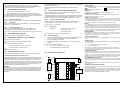
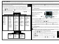
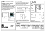
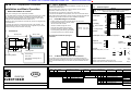
For More Free Controller Manuals Please Visit
3216 PID Temperature Controller
1.2.
3.
Step 1: Installation
This instrument is intended for permanent installation, for indoor use only, and
enclosed in an electrical panel
Installation and Basic Operation
1.
www.HVACRinfo.com
3.1.
Terminal Layout
Warning
!
Select a location which is subject to minimum vibrations and the ambient
o
o
temperature is within 0 and 55 C (32 - 122 F)
WHAT INSTRUMENT DO I HAVE?
STEP 2: WIRING
Ensure that you have the correct supply for your controller
Check order code of the controller supplied
The instrument can be mounted on a panel up to 15mm thick
Thank you for choosing the 3216 Temperature Controller.
To ensure IP65 and NEMA 4 front protection, mount on a non-textured surface.
This User Guide takes you through step by step instructions to help you to install,
wire, configure and use the controller. For features not covered in this User
Guide, a detailed Engineering Manual, Part No HA027986, and other related
handbooks can be downloaded from www.eurotherm.co.uk
Please read the safety information in section 4 before proceeding and refer to the
EMC Booklet part number HA025464 for further installation information.
Depending on how it was ordered, the controller may need to be configured when
it is first switched on.
1.
Prepare a square cut-out in the mounting panel to the size shown
2.
Fit the IP65 sealing gasket, if required, behind
the front bezel of the controller
Line Supply
3.
Insert the controller through the cut-out
85 - 264Vac 50/60Hz
4.
Spring the panel retaining clips into place.
Secure the controller in position by holding it
level and pushing both retaining clips forward.
The ordering code is shown on a label fixed to the side of the controller. The
hardware installed and the way in which it has been configured may be checked
against the ordering code at the bottom of this page.
1.1.
Dimensions
1.2.1.
5.
90mm (3.54in)
48mm (1.89in)
Input/Output 1
1A
CT in
1B
Dig in
Panel Mounting the Controller
2A
Output 2
2B
L
N
OR
45 mm - 0.0 + 0.6
1.77 in -0.00, +0.02
Digital
Comms
CT
AA
C
AB
LA
AC
B
HD
VI
HE
V+
HF
V-
Output AA
PV Input
Low Voltage Supply
24
24Vac/dc
Peel off the protective cover from the display
24
+
Recommended minimum spacing of
controllers
Output AA
Changeover Relay
AA
+
Output 2
Relay or Logic
AB
-
AC
Panel retaining clips
IP65 Sealing Gasket
Latching ears
PV Input
mV
Thermocouple, PRT, mA or mV
1.2.2.
Issue 1.0
June-03
T/C
2B
VI
+
-
To Remove the Controller from its Sleeve
The controller can be unplugged from its sleeve by easing the latching ears
outwards and pulling it forward out of the sleeve. When plugging it back into its
sleeve, ensure that the latching ears click back into place to maintain the IP65
sealing.
V+
Digital Communications
RS232 Connect directly to comms port of PC
RS485 Daisy chain to further controllers/comms converter
V-
Com
HD
A+(Rx)
HE
B-(Tx)
HF
ORDER CODE
3216
ENG
PRT
+
+
-
2.
Part No. HA027985
mA
2A
2.49Ω
Label showing
Serial Number including date of
manufacture
3216 User Guide
38mm
(1.5 in)
(Not to
scale)
Order Code
1B
-
48mm
(1.89in)
10mm
(0.4 in)
1A
Input/Output 1 Relay or Logic Output or Digital Input
CC
Power Supply
20 – 29V
110 –240V
Power
supply
VL
VH
Input/output 1 & output 2
Input/output 1 & Output 2
OP1
OP2
L
X
Logic I/O
L
L
Logic I/O + logic OP
L
R
Logic I/O + relay
R
R
Relay + relay
X
X
Not fitted
X
Output AA
Comms, CT & Digital input
Output AA
Relay (Form C)
Not fitted
R
X
Fascia colour
Language
Communications, CT & Digital input
X
X
X
Not fitted
4
X
L
RS485 comms & dig in
2
X
L
RS232 comms & dig in
4
C
L
RS485 comms CT & dig in
2
C
L
RS232 comms CT & dig in
X
X
L
Digital input
X
C
L
CT and digital input
Quick start code
Language
English
E
Fascia colour
Green
G
Silver
S
Quick Start Code
See Switch On
section
3.2.
Wire Sizes
The screw terminals accept wire sizes from 0.5 to 1.5 mm (16 to 22AWG).
Hinged covers prevent hands or metal making accidental contact with live wires.
The rear terminal screws should be tightened to 0.4Nm (3.5lb in).
3.3.
1.
2.
PV Input (Measuring Input)
Do not run input wires together with power cables
When shielded cable is used, it should be grounded at one point only
Any external components (such as zener barriers, etc) connected between sensor
and input terminals may cause errors in measurement due to excessive and/or unbalanced line resistance or possible leakage currents
3.3.1.
Thermocouple Input
3.7.
Digital communications (Optional)
4.
Digital communications uses the Modbus protocol. The interface may be ordered
as RS232 or RS485 (2-wire).
Current Transformer/Logic Input (Optional)
A digital (logic) input from a volt free contact can be configured to select Setpoint
2, Keylock, Run/Hold, Reset, Alarm Acknowledge or Auto/Manual. The common
connection is shared for each of these inputs and is, therefore, not isolated.
To prevent hands or metal tools touching parts that may be electrically live, the
controller must be enclosed in an enclosure.
CT input resolution – 0.1A for scale up to 10A, 1A for scale 11 to 100A
Linear Input (mA or V)
Current Transformer Input
CT input current 0 to 50mA rms (sine wave) 50/60Hz, input impedance <20Ω
CT input accuracy – 4% of reading
3.8.2.
For mA input connect burden resistor of 2.49Ω across the + and - input as shown
AA Output Relay (Optional)
Changeover relay (Form C) rated 2A 264Vac resistive
The installation must include a power isolating switch or circuit breaker. This device
should be in close proximity to the controller, within easy reach of the operator and
marked as the disconnecting device for the instrument.
Power Supply
Before connecting the instrument to the power line, make sure that the line
voltage corresponds to the description on the identification label
This may be an input or an output
2.
For 24V the polarity is not important
Relay output normally open (Form A), 2A 264Vac resistive
3.
OR
Logic output to drive SSR (not isolated)
The power supply input is not fuse protected. This should be provided
externally:
Instrument fuse ratings are as follows:-
Input/Output 1 (Relay or Logic - Optional)
Logic level On/High - 12Vdc at 5 to 40mA max
•
For 24 V ac/dc fuse type T rated 2A 250V
Logic level Off/Low - <100mV <100µA
•
For 85/265Vac fuse type T rated 2A 250V
OR
Digital Input (contact closure)
3.6.
Output 2 (Relay or Logic)
This is optional and is output only. It may be relay or logic output as output 1.
* General Note About Relays and Inductive Loads
High voltage transients may occur when switching inductive loads such as some
contactors or solenoid valves. Through the internal contacts, these transients may
introduce disturbances which could affect the performance of the instrument.
Wiring
Power Isolation
1.
3.5.
The controller is designed to operate with the temperature sensor connected directly to
an electrical heating element. However you must ensure that service personnel do not
touch connections to these inputs while they are live. With a live sensor, all cables,
connectors and switches for connecting the sensor must be mains rated.
contact closed < 200Ω
Note: This supplies 12Vdc up to 10mA to terminal LA
3.9.
Caution: Live sensors
contact open > 500Ω
Contact closure 12V @ 5-40mA
For volts input an external module is required. Input resistance 100KΩ.
Enclosure of Live Parts
It is important to connect the controller in accordance with the wiring data given in this
guide. Take particular care not to connect AC supplies to the low voltage sensor input
or other low level inputs and outputs. Only use copper conductors for connections
(except thermocouple inputs) and ensure that the wiring of installations comply with all
local wiring regulations. For example in the UK use the latest version of the IEE wiring
regulations, (BS7671). In the USA use NEC Class 1 wiring methods.
Logic Input
Digital Input
A line resistance for voltage inputs may cause measurement errors
3.4.
Equipment protected throughout
by DOUBLE INSULATION
Installation must only be carried out by suitably qualified personnel
3.3.2.
3.3.3.
Caution, (refer to
accompanying documents)
Personnel
3.8.1.
The resistance of the three wires must be the same. The line resistance may
cause errors if it is greater than 22Ω
!
A current transformer can be connected directly to the controller to monitor the
actual current supplied to an electrical load.
For thermocouple input use the correct compensating cable preferably shielded
RTD Input
Various symbols may be used on the controller. They have the following meaning:
For further details see Series 2000 Communications Handbook Part No
HA026230.
3.8.
INSTALLATION SAFETY REQUIREMENTS
Safety Symbols
Overcurrent protection
The power supply to the system should be fused appropriately to protect the cabling to
the units.
Voltage rating
The maximum continuous voltage applied between any of the following terminals must
not exceed 264Vac:
relay output to logic, dc or sensor connections;
any connection to ground.
The controller must not be wired to a three phase supply with an unearthed star
connection. Under fault conditions such a supply could rise above 264Vac with respect
to ground and the product would not be safe.
Conductive pollution
Electrically conductive pollution must be excluded from the cabinet in which the
controller is mounted. For example, carbon dust is a form of electrically conductive
pollution. To secure a suitable atmosphere in conditions of conductive pollution, fit an
air filter to the air intake of the cabinet. Where condensation is likely, for example at
low temperatures, include a thermostatically controlled heater in the cabinet.
3.10. Example Wiring Diagram
L
Over-temperature protection
Heater
fuse
For this type of load it is recommended that a ‘snubber’ is connected across the
normally open contact of the relay switching the load. The snubber recommended
consists of a 15nF series connected resistor/capacitor (typically 15nF/100Ω). A
snubber will also prolong the life of the relay contacts.
Solid
State
Relay
(e.g.
TE10)
WARNING
When the relay contact is open or it is connected to a high impedance load, the
snubber passes a current (typically 0.6mA at 110Vac and 1.2mA at 240Vac). It is
the responsibility of the installer to ensure that this current does not hold on the
power to an electrical load. If the load is of this type the snubber should not be
connected.
Relay output fuse
Controller fuse
1A
JA
CT
AA
1B
C
AB
2A
LA
Snubber*
AC
Cooling or
alarm relay
BA
Heater
N
2B
HD
VI
L
HE
V+
N
JF
HF
V-
+
T/C
-
Where damage or injury is possible, we recommend fitting a separate over-temperature
protection unit, with an independent temperature sensor, which will isolate the heating
circuit.
Please note that the alarm relays within the controller will not give protection under all
failure conditions.
Installation requirements for EMC
To ensure compliance with the European EMC directive certain installation precautions
are necessary as follows:
For general guidance refer to Eurotherm Controls EMC Installation Guide, HA025464.
When using relay outputs it may be necessary to fit a filter suitable for suppressing the
emissions. The filter requirements will depend on the type of load. For typical
applications we recommend Schaffner FN321 or FN612.
5.
STEP 3: SWITCH ON
A brief start up sequence consists of a self test in which all bars of the display are illuminated and the software version is shown. What happens next depends on whether the instrument is new or has been switched on before.
For a new controller go to section 5.1. for an instrument already configured go to section 5.2.
5.1.
5.1.1.
New Controller (Unconfigured)
To Re-enter Quick configuration Mode
When the controller is switched on it will start up showing the ‘Quick Configuration’ codes. This enables you
to configure the controller to match the process.
This mode can always be entered by holding down the
defaulted to 4.
The quick code consists of two ‘SETS’ of five characters. The upper section of the display shows the set
selected, the lower section shows the five digits which make up the set. Adjust these to suit your process as follows:-
Note:- If during normal operation a change is made to any of the parameters in the quick code list, then the quick code
displayed during power up will show the characters separated by decimal points. The controller can be left to operate in this
way.
1.
Press any button. The * characters will change to ‘-‘. The first one flashing.
2.
Press
or
to change the character currently flashing to the code as shown in the tables below
to scroll to the next character (press
3.
Press
configured in Set 1 the display will go to Set 2.
4. When the last digit has been selected press
controller will re-start. Now go to section 5.2
to return to the first character). When all five characters have been
again, the display will show E X IT. Press
or
Range
C = oC Full Range
F = oF Full Range
0 = 0-100OC
1 = 0-200OC
2 = 0-400OC
3 = 0-600OC
4 = 0-800OC
5 = 0-1000OC
6 = 0-1200OC
7 = 0-1400OC
8 = 0-1600OC
9 = 0-1800OC
G = 32-212OF
H= 32-392OF
J= 32-752OF
K = 32-1112OF
L = 32-1472OF
M = 32-1832OF
N = 32-2192OF
P = 32-2552OF
R = 32-2912OF
T = 32-3272OF
SET 2
I/O Module 1
Control
H = PID heat
C = PID cool
J = On/off heat
K = On/off cool
Alarm 1 (energised
in alarm)
0 = High
1 = Low
2 = Deviation high
3 = Deviation low
4 = Deviation band
Alarm 1 (deenergised in alarm)
5 = High
6 = Low
7 = Deviation high
8 = Deviation low
9 = Deviation band
Logic Input
W = Alarm ack
M = Manual
R = Run/hold
L = Key lock
P = Setpoint 2
T = Reset
Output Module 2
Control
H = PID heat
C = PID cool
J = On/off heat
K = On/off cool
Alarm 2 (energised
in alarm)
0 = High
1 = Low
2 = Deviation high
3 = Deviation low
4 = Deviation band
Alarm 2 (deenergised in alarm)
5 = High
6 = Low
7 = Deviation high
8 = Deviation low
9 = Deviation band
Normal Operation
The controller will start up in operator level 1 and in the mode in which was last switched off. AUTO is the normal closed loop
temperature control mode which means that the output power is adjusted automatically by the controller in response to the
measurement from the input sensor. In this mode you will see the display shown below. It is called the HOME display.
Output Relay AA
Control
H = PID heat
C = PID cool
J = On/off heat
K = On/off cool
Alarm 3 (energised
in alarm)
0 = High
1 = Low
2 = Deviation high
3 = Deviation low
4 = Deviation band
Alarm 3 (deenergised in alarm)
5 = High
6 = Low
7 = Deviation high
8 = Deviation low
9 = Deviation band
Actual Temperature
(or Process Value ‘PV’)
OP1 lit when output 1 is ON (normally heating).
OP2 lit when output 2 is ON (normally cooling ).
OP4 lit when AA output is ON
SPX Alternative setpoint in use SP2
RUN Timer running
MAN Manual
Page button
ALM Alarm active (Red)
Required Temperature
(or Setpoint ‘SP’)
Raise button
Lower button
Scroll button
When this view is first entered (or
is pressed) the lower display scrolls a ‘help’ message which gives the name of the
parameter being displayed, e.g. ‘w o rk in g s e tp o in t’
In level 1 you can acknowledge alarms, adjust temperature setpoint, select auto or manual operation as described below:-
5.2.1.
To Acknowledge an Alarm. Press
and
together
If an alarm is still current the red ALM beacon will flash, a scrolling message will give the source of the alarm and any relay
attached to the alarm will operate. When acknowledged, these functions will change as described in section 6.2.
5.2.2.
To Set The Required Temperature. Press
to raise the setpoint, or
to lower the setpoint –
when the HOME display is being shown. The new setpoint is entered when the button is released and is indicated by a brief
flash of the display.
5.2.3.
Manual operation
The controller can be set so that the output power can be adjusted directly by the operator. This may be useful during
commissioning or if the sensor becomes faulty and it is required to continue temporary operation of the plant until the sensor
is repaired or replaced.
!
Manual operation must be used with care and the power level set must be chosen such that no damage can
occur to the process. The use of a separate ‘over-temperature’ controller is recommended.
5.2.4.
* WXXT
Input CT Scaling
Digital Input
Lower Display
1 = 10 Amps
2 = 25 Amps
5 = 50 Amps
6 = 100 Amps
W = Alarm Ack
M = Manual
R = Run/hold
L = Keylock
P = Setpoint 2
T = Reset
T = Setpoint
P = Output power %
R = Time to run
E = Elapsed time
1 = Alarm 1 setpoint
A = Amps
N = None
In any column, - = Unconfigured: X = Not fitted
5.2.
to YES. The
KCHC0
SET 1
In put Sensor type
Thermocouple
B = Type B
J = Type J
K = Type K
L = Type L
N = Type N
R = Type R
S = Type S
T = Type T
C = Custom
RTD
P = Pt100 PRT
Linear
M = 0-80mV
2 = 0-20mA
4 = 4-20mA
x indicates the option is not fitted
button during power up and then entering a passcode. This is
To Select Manual Operation and Adjust the Output Power
1.
Press and hold
and
together. ‘Auto’ is shown in the upper display. The lower display will
scroll the longer alternate description of this parameter, ie ‘lo o p m o d e – a u to m a n u a l o ff’
2.
3.
to select ‘mAn’. This is shown in the upper display and the MAN beacon is lit.
Press
The controller will return to the HOME display. The upper display is the PV. The lower display is the
demand power.
4.
Press
or
to raise or lower the power. The output power is continuously updated when the
buttons are pressed
5.
To Return to Automatic operation, press and hold
select ‘Auto
and
together. Then press
to
7.
TIMER OPERATION
7.1.
A timer can be configured to operate in three different modes. These can be
selected in Level 2.
1.
Dwell timer
2.
Delayed switch on timer
3.
Soft start timer
There are four operating states, all of which are available in Level 1:
Run may be initiated by pressing
and
A dwell timer (TI.CFG = DWELL) is used to control a process at a fixed
temperature for a defined period. The action which occurs at the end of the
timed period depends on the configuration of the END.T parameter.
OFF
and
(Note pressing Ack at this point does not reset the timer. The reason for this
is that if the display is on any view other than the HOME display then
pressing these two buttons will jump to HOME).
hold, press quickly
and
and
To run the timer from
again
The above states may also be set by the following methods:•
Edge trigger a suitably configured digital input
•
Power cycle the controller
•
Digital communications command
End cannot be set - it occurs automatically when the timer has counted
down to zero
Switching from Hold to Run through the front panel buttons is not allowable
if the Hold status is forced by a logic input or through Digital
Communications.
Timer operation is indicated by a beacon labelled RUN:
Timer Status
Reset
Run
Hold
End
RUN beacon
Off
On
Flashing
Off
Logic outputs The timer may be configured to operate an output when it is
running or during the end state
Note:•
•
•
•
SP2
dwel
Power up - the ‘run’ state is selected if a Soft Start or Delay
timer is configured or the ‘Reset’ state is selected if a Dwell timer
is configured.
Auto/Manual is only available when the timer is in Reset
Ramp Rate – it is recommended that ramp rate is used only with
a Dwell type timer
Quick access to the timer operating parameters is available in
. Repeat pressing of this button shows
Level 2 by pressing
Timer Status, Dwell, Working Output, SP1, SP2, etc
Time
THRES
=+n
SP1
Counting
down
(Ack),
Hold may be initiated by pressing
SP1 (70)
Temp
together.
Reset, during timing, may be initiated by pressing and holding
Temperature
End State e n d . t =
Reset (of End State) when timer has timed out, may be initiated by pressing
and
When the timer status = reset, the control output is controlling at SP1
Dwell Timer
Scrolling
message
OFF
TIMER RUNNING
Scrolling
Message
SP2
TIMER END
OFF
Digital
input
RUN Digital O/P = t.run
END Digital O/P = t.End
END Digital O/P = t.End
Notes:
1.
If THRES = 2o (for example) timer will show TIMER RUNNING with
the RUN beacon on but will not start counting down until the
temperature is, first, within 2o of SP. Then the threshold is ignored.
2.
The DWELL period can be reduced or increased when the timer is
running. If it is reduced to meet the Time Elapsed the timer will
change to the End state.
3.
A-M can only be selected when in reset
4.
If the timer is re-configured to a different type or the End Type is reconfigured (a dwell, for example), it may be necessary to reselect Auto
mode
Temp
DWELL
THRES
= +n
Servo
to PV
start
Scrolling
message
Ramp to
Ramp to
SP1 at
SP2 at
SP.RAT
SP.RAT
Counting down
TIMER RUNNING
7.3.
Soft Start Timer
The timer is used to start a process at reduced power and/or reduced
setpoint. Timing starts at power up or when ‘Run’ is selected.
When the Timer Status = Run, the controller power is limited by the soft
start power limit parameter. The Soft Start setpoint is a threshold which,
when exceeded, sets the timer to end. If the temperature is already above
this threshold when the timer is set to run, the timer will time out
immediately.
When the timer status = reset, the controller is controlling at SP1
Simple Programmer
A four segment programmer is achieved using a dwell type timer with the set
point rate limit and threshold parameters set.
SP2
(20 oC)
Reset
RESET
RUN Digital O/P = t.run
SP1
(70 oC)
Run
Time
OFF
RESET
Digital Input
7.1.1.
TIMER RUNNING TIMER END
Temp
Setpoint (70oC)
Soft start setpoint
S S . S P (50 oC)
Time
Output power High limit
TIMER
END
Time
Timer soft start power limit
S S . P W R (40%)
Scrolling
Message
RESET
Digital
input
Time
TIMER
RUNNING
Run
RUN Digital O/P = t.run
END Digital O/P = t.End
RESET
Digital input
RUN Digital O/P = t.run
7.2.
Delayed Switch On timer
The timer is used to switch on the output power after a set time.
When the timer status = run, the control output is off
END Digital O/P = t.End
TIMER
END
Reset
7.4.
7.4.3.
To Run A Timer
The example given here is for the simple programmer shown in section 7.1.1. with the following settings:o
Type = Dwell
SP1 = 70 C
o
o
End.T = SP2 = 20 C
Ramp Rate Set to 20 C/min
o
Threshold = 1 C
At start of run the controller servos to PV (starts at the current temperature). The procedure to Run, Hold, or Reset is the same for all timer types.
At start of run controller servos to PV and , therefore, starts at the current temperature
Do This
The Display You Should See
Power Cycling
If the power is turned off when the timer is running it will come back on
as follows:For a Dwell type timer it will come back on in Reset
For a Delayed Switch on timer or a Soft Start timer, the controller will
come back on in the Run condition and start again from the beginning.
Additional Notes
RUN beacon on
1.
Momentarily press
together)
36
43
and
RUN
Scrolling display ‘tim e r
ru n n in g ’
o
o
Controller ramping up to SP1 (70 C) at the set rate (20 C/min max for this
example)
When SP1 reached the controller will control at this temperature until the end
of the DWELL period set. This is from the point at which the timer was set to
run.
8.
FURTHER LEVELS OF OPERATION
Access to further levels of operation are described in the Engineering
Handbook Part No HA027986 available on www.eurotherm.co.uk
To ensure the dwell starts from SP1 (or close to) set THRES = a small value
(eg2)
20
20
SPX
2.
e n d ’ will be indicated
Controller ramp to SP2 (20oC) at the set rate (20oC /min max for this
example)
SPX beacon on
20
20
Press
and
(Ack)
together to reset the timer
When timed out Scrolling display ‘tim e r
SPX
RUN beacon off
Controller controlling at SP2 (20oC)
TIMER END message cancelled
SPX beacon on (indicating control at SP2)
The timer can be run again from this point
7.4.1.
To Hold the Timer
While the timer is running it can be put into Hold (timer stops counting down)
Do This
3.
4.
7.4.2.
Momentarily press
together)
The Display You Should See
and
Momentarily press
and
together to run the timer from the
hold condition
36
47
36
47
RUN
Additional Notes
RUN beacon flashing
Scrolling display ‘tim e r
h o ld ’
Controller controlling at SP1 (70 oC)
RUN beacon on
Scrolling display ‘tim e r
ru n n in g ’
o
Controller continues controlling at SP1 (70 C)
To Reset the Timer
While the timer is running it can be Reset
Do This
5.
Press and hold
together)
The Display You Should See
and
70
70
Additional Notes
When the timer is running it cannot be reset using the Ack button(s) since
pressing these will return the display to the HOME display
If reset T.REMN and T.ELAP stay at their values prior to reset. These reset
to their start values when the timer is run again
This indicator meets the European directives on safety and EMC
3216 User Guide
Part No. HA027985
Issue 1.0E
May 03