1
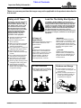
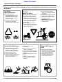
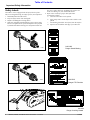
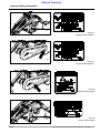
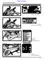
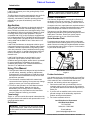
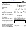
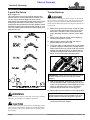
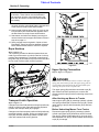
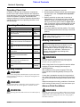
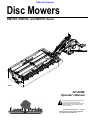
Table of Contents
Disc Mowers
DM3705, DM3706, and DM3707 Series
21019
327-083M
Operator’s Manual
!
Read the Operator’s manual entirely. When
you see this symbol, the subsequent
instructions and warnings are serious - follow
without exception. Your life and the lives of
others depend on it!
© Copyright 2006 Printed
9/15/06
Cover photo may show optional equipment
not supplied with standard unit.
Land Pride.
Table of Contents
Table of Contents
Important Safety Information . . . . . . . . . . .1
Section 3: Adjustments . . . . . . . . . . . . . .20
Safety Labels . . . . . . . . . . . . . . . . . . . . . . . . . . . . . . . . . . 4
Belt Tension Adjustment . . . . . . . . . . . . . . . . . . . 20
Cutting Height . . . . . . . . . . . . . . . . . . . . . . . . . . . 20
Introduction . . . . . . . . . . . . . . . . . . . . . . . .7
Application . . . . . . . . . . . . . . . . . . . . . . . . . . . . . . . 7
Using This Manual . . . . . . . . . . . . . . . . . . . . . . . . . 7
Owner Assistance . . . . . . . . . . . . . . . . . . . . . . . . . 7
Section 1: Assembly and Set-Up . . . . . . . .8
Tools Required . . . . . . . . . . . . . . . . . . . . . . . . . . . 8
Assembly Preparation . . . . . . . . . . . . . . . . . . . . . . 8
Gearbox and Cutter Bar Lubrication . . . . . . . . . 8
Main Frame to Cutter Bar Assembly . . . . . . . . . . . 9
PTO Guard Assembly . . . . . . . . . . . . . . . . . . . . . . 9
Support Stand Assembly . . . . . . . . . . . . . . . . . . . . 9
Cutter Bar Assembly . . . . . . . . . . . . . . . . . . . . . . 10
Main Frame Assembly (Back Side) . . . . . . . . . . . 11
Canvas Curtain Assembly . . . . . . . . . . . . . . . . . . 12
Section 2: Operating . . . . . . . . . . . . . . . .13
3-point Pin Set-up . . . . . . . . . . . . . . . . . . . . . . . . 13
Tractor Hook-up . . . . . . . . . . . . . . . . . . . . . . . . . . 13
Driveline Installation . . . . . . . . . . . . . . . . . . . . . . . 14
Checking Driveline Minimum Length . . . . . . . . 14
Rope Hook-up . . . . . . . . . . . . . . . . . . . . . . . . . . . 15
Transport Latch Operation . . . . . . . . . . . . . . . . . . 15
Upper Spring Connection . . . . . . . . . . . . . . . . . . . 15
After Hooking-up Mower to Tractor . . . . . . . . . 15
Before Unhooking Mower From Tractor . . . . . 15
Spring Tension Adjustment . . . . . . . . . . . . . . . . . 16
Adjusting Lower Spring Tension . . . . . . . . . . . 16
Adjusting Upper Spring Tension . . . . . . . . . . . 16
Transporting . . . . . . . . . . . . . . . . . . . . . . . . . . . . 16
Operating Check List . . . . . . . . . . . . . . . . . . . . . . 17
Working Position . . . . . . . . . . . . . . . . . . . . . . . . . 17
Mowing Instructions . . . . . . . . . . . . . . . . . . . . . . . 17
Adverse Field Conditions . . . . . . . . . . . . . . . . . . . 17
Safety Break-Away . . . . . . . . . . . . . . . . . . . . . . . 18
Operating Instructions . . . . . . . . . . . . . . . . . . . . . 18
Section 4: Maintenance and Lubrication 21
General Maintenance . . . . . . . . . . . . . . . . . . . . . . 21
At beginning of season: . . . . . . . . . . . . . . . . . . 21
Servicing Blades . . . . . . . . . . . . . . . . . . . . . . . . . 21
Blade Replacement . . . . . . . . . . . . . . . . . . . . . 21
Blade Fastener Replacement . . . . . . . . . . . . . 21
Belleville Washer Replacement . . . . . . . . . . . . 22
Blade & Belleville Washer Pt. No’s. . . . . . . . . . . . 22
Cutter Bar Timing Adjustment . . . . . . . . . . . . . . . 22
Storage . . . . . . . . . . . . . . . . . . . . . . . . . . . . . . . . 22
Lubrication . . . . . . . . . . . . . . . . . . . . . . . . . . . . . . 23
Driveline Inner Tube . . . . . . . . . . . . . . . . . . . . 23
Driveline U-Joints . . . . . . . . . . . . . . . . . . . . . . 23
Gearbox . . . . . . . . . . . . . . . . . . . . . . . . . . . . . 23
Cutter Bar . . . . . . . . . . . . . . . . . . . . . . . . . . . . 24
Frame Pivot Point . . . . . . . . . . . . . . . . . . . . . . 24
Hitch Pivot Point . . . . . . . . . . . . . . . . . . . . . . . 24
Section 5: Specifications & Capacities . .25
Section 6: Features & Benefits . . . . . . . .26
Section 7: Troubleshooting . . . . . . . . . . .27
Section 8: Appendix . . . . . . . . . . . . . . . . .28
Torque Values Chart for Common Bolt Sizes . . . . 28
Warranty . . . . . . . . . . . . . . . . . . . . . . . . . . . . . . . 29
© Copyright 2006 All rights Reserved
Land Pride provides this publication “as is” without warranty of any kind, either expressed or implied. While every precaution has been taken in the preparation of this manual, Land
Pride assumes no responsibility for errors or omissions. Neither is any liability assumed for damages resulting from the use of the information contained herein. Land Pride reserves
the right to revise and improve its products as it sees fit. This publication describes the state of this product at the time of its publication, and may not reflect the product in the future.
Land Pride is a registered trademark.
All other brands and product names are trademarks or registered trademarks of their respective holders.
Printed in the United States of America.
DM3705, DM3706, and DM3707 Series Disc Mowers 327-083M
9/15/06
▲
Table of Contents
Important Safety Information
Important Safety Information
These are common practices that may or may not be applicable to the products described in
this manual.
Safety at All Times
Look For The Safety Alert Symbol
Thoroughly read and understand
the instructions given in this
manual before operation. Refer to
the “Safety Label” section, read
all instructions noted on them.
Do not allow anyone to operate
this equipment who has not fully
read and comprehended this
manual and who has not been
properly trained in the safe
operation of the equipment.
The SAFETY ALERT SYMBOL indicates there is a
potential hazard to personal safety involved and extra
safety precaution must be taken. When you see this
symbol, be alert and carefully read the message that
follows it. In addition to design and configuration of
equipment, hazard control and accident prevention
are dependent upon the awareness, concern,
prudence and proper training of personnel involved in
the operation, transport, maintenance and storage of
equipment.
▲ Operator should be familiar with
all functions of the unit.
▲ Operate implement from the
driver’s seat only.
▲ Make sure all guards and shields
are in place and secured before
operating the implement.
▲ Do not leave tractor or implement
unattended with engine running.
▲ Dismounting from a moving
tractor could cause serious injury
or death.
▲ Do not stand between the tractor
and implement during hitching.
▲ Keep hands, feet, and clothing
away from power-driven parts.
▲ Wear snug fitting clothing to avoid
entanglement with moving parts.
▲ Turning tractor too tight may
cause implement to ride up on
wheels. This could result in injury
or equipment damage.
!
Be Aware of
Signal Words
! WARNING
A Signal word designates a degree or
level of hazard seriousness. The
signal words are:
! DANGER
Indicates a potentially hazardous
situation which, if not avoided, could
result in death or serious injury, and
includes hazards that are exposed
when guards are removed. It may also
be used to alert against unsafe
practices.
! CAUTION
Indicates an imminently hazardous
situation which, if not avoided, will
result in death or serious injury. This
signal word is limited to the most
extreme situations, typically for
machine components that, for
functional purposes, cannot be
Indicates a potentially hazardous
situation which, if not avoided, may
result in minor or moderate injury. It
may also be used to alert against
unsafe practices.
For Your Protection
Shutdown and Storage
▲ Thoroughly read and understand
▲ Lower machine to ground, put
the “Safety Label” section, read all
instructions noted on them.
tractor in park, turn off engine, and
remove the key.
▲ Detach and store implements in a
area where children normally do
not play. Secure implement by
using blocks and supports.
OFF
REMO
VE
9/15/06
DM3705, DM3706, and DM3707 Series Disc Mowers 327-083M
1
Table of Contents
Important Safety Information
These are common practices that may or may not be applicable to the products described in
this manual.
Use Safety
Lights and Devices
▲ Slow moving tractors,
self-propelled equipment, and
towed implements can create a
hazard when driven on public
roads. They are difficult to see,
especially at night.
▲ Flashing warning lights and turn
signals are recommended
whenever driving on public roads.
Practice Safe Maintenance
▲ Understand procedure before
doing work. Use proper tools and
equipment, refer to Operator’s
Manual for additional information.
▲ Work in a clean dry area.
▲ Lower the implement to the
ground, put tractor in park, turn off
engine, and remove key before
performing maintenance.
2
Transport
Machinery Safely
▲ Comply with state and local laws.
▲ Maximum transport speed for
implement is 20 mph. DO NOT
EXCEED. Never travel at a speed
which does not allow adequate
control of steering and stopping.
Some rough terrain require a
slower speed.
▲ Sudden braking can cause a
towed load to swerve and upset.
Reduce speed if towed load is not
equipped with brakes.
▲ Allow implement to cool
completely.
▲ Do not grease or oil implement
while it is in operation.
▲ Inspect all parts. Make sure parts
are in good condition & installed
properly.
▲ Remove buildup of grease, oil or
debris.
▲ Remove all tools and unused
parts from implement before
operation.
DM3705, DM3706, and DM3707 Series Disc Mowers 327-083M
▲ Use the following maximum
speed - tow load weight ratios as
a guideline:
▲ 20 mph when weight is less than
or equal to the weight of tractor.
▲ 10 mph when weight is double
the weight of tractor.
▲ IMPORTANT: Do not tow a load
that is more than double the
weight of tractor.
Tractors With Cabs or
ROPS
▲ There should be sufficient
clearance for the operator when
mounted to a tractor with a cab or
that is equipped with ROPS.
▲ The ROPS may need to be
extended or flipped around to
obtain sufficient clearance.
9/15/06
Table of Contents
Important Safety Information
These are common practices that may or may not be applicable to the products described in
this manual.
Prepare for Emergencies
▲ Be prepared if a fire starts.
▲ Keep a first aid kit and fire
extinguisher handy.
▲ Keep emergency numbers for
doctor, ambulance, hospital and
fire department near phone.
Wear
Protective Equipment
▲ Protective clothing and equipment
should be worn.
▲ Wear clothing and equipment
appropriate for the job. Avoid
loose fitting clothing.
▲ Prolonged exposure to loud noise
can cause hearing impairment or
hearing loss. Wear suitable
hearing protection such as
earmuffs or earplugs.
▲ Operating equipment safely
requires the full attention of the
operator. Avoid wearing radio
headphones while operating
machinery.
911
Keep Riders
Off Machinery
Tire Safety
▲ Riders obstruct the operator’s
and should be performed by
trained personnel using the
correct tools and equipment.
▲ When inflating tires, use a clip-on
chuck and extension hose long
enough to allow you to stand to
one side and NOT in front of or
over the tire assembly. Use a
safety cage if available.
▲ When removing and installing
wheels, use wheel handling
equipment adequate for the
weight involved.
view, they could be struck by
foreign objects or thrown from the
machine.
▲ Never allow children to operate
equipment.
9/15/06
▲ Tire changing can be dangerous
DM3705, DM3706, and DM3707 Series Disc Mowers 327-083M
3
Table of Contents
Important Safety Information
Safety Labels
Your Mower comes equipped with all safety labels in place.
They were designed to help you safely operate your implement.
1. Read and follow label directions.
2. Keep all safety labels clean and legible.
3. Replace all damaged or missing labels.
4. Some new equipment installed during repair require safety
labels to be affixed to the replaced component as specified
by Land Pride. When ordering new components make sure
the correct safety labels are included in the request. To
order new labels go to your Land Pride dealer.
5. Refer to this section for proper label placement.
To install new labels:
a. Clean area the label is to be placed.
b. Spray soapy water on the surface where label is to be
placed.
c. Peel backing from label. Press firmly onto the surface.
d. Squeeze out air bubbles with edge of a credit card.
818-540C
13102
Danger Guard Missing
ROTATING DRIVELINE
KEEP AWAY!
13102
818-552C
Danger PTO Driveline
818-626C
21020
4
DM3705, DM3706, and DM3707 Series Disc Mowers 327-083M
Danger Crushing Hazard
9/15/06
Table of Contents
Important Safety Information
21021
818-641C
Danger Rotating Blades
21020
818-641C
Danger Rotating Blades
21020
818-642C
Danger Thrown Object
21021
818-132C
Danger Thrown Object
9/15/06
DM3705, DM3706, and DM3707 Series Disc Mowers 327-083M
5
Table of Contents
Important Safety Information
21021
838-094C
Warning: High Pressure
838-824C
Danger: Pinch Point Hazard
21021
818-558C
21020
Warning:
General Mower Safety
818-543C
21025
6
DM3705, DM3706, and DM3707 Series Disc Mowers 327-083M
Warning Guard Missing
9/15/06
Table of Contents
Introduction
Introduction
Land Pride welcomes you to the growing family of new
product owners.
This Disc Mower has been designed with care and built
by skilled workers using quality materials. Proper
assembly, maintenance, and safe operating practices
will help you get years of satisfactory use from the
machine.
Application
The Land Pride Disc Mowers are designed and built to
cut hay, grass, and other cultivated forage crops on
farms, ranches, set-aside acres, and right-of-ways. They
are adapted for 540 rpm 3-point hitch Category II offset
mounting and are Quick-Hitch adaptable. They are
compatible with 35 HP to 80 HP tractors equipped with
live or independent PTO’s. The DM3705 has 5 discs and
an 82" cutting width. The DM3706 has 6 discs and a 96"
cutting width and the DM3707 has 7 discs and a 112"
cutting width.
Land Pride Disc Mowers are designed to deliver good
cutting performance even in thick, tangled, and wet grass
conditions. Standard replaceable rock guards provide
cutter bar protection in stony conditions and will greatly
extend cutter bar life. A standard break-away latch will
release, allowing the cutter bar to swing back, if an
obstacle is hit.
NOTE: A special point of information that the
operator must be aware of before continuing.
Owner Assistance
The Warranty Registration card should be filled out by
the dealer at the time of purchase. This information is
necessary to provide you with quality customer service.
If customer service or repair parts are required contact a
Land Pride dealer. A dealer has trained personnel, repair
parts and equipment needed to service the mower.
The parts on your Disc Mower have been specially
designed and should only be replaced with genuine Land
Pride parts. Therefore, should your mower require
replacement parts go to your Land Pride Dealer.
Serial Number Plate
For prompt service always use the serial number and
model number when ordering parts from your Land Pride
dealer. Be sure to include your serial and model numbers
in correspondence also. Refer to Figure 1 for the location
of your serial number plate.
Land Pride Disc Mowers are well suited for use in
agricultural regions where humidity and moisture
conditions are typically higher, where there is a potential
for crop entanglement, and where tough ground
conditions are present. See “Features and Benefits”,
“Section 5” for additional information.
Using This Manual
• This Operator’s Manual is designed to help familiarize
•
you with safety, assembly, operation, adjustments,
troubleshooting, and maintenance. Read this manual
and follow the recommendations to help ensure safe
and efficient operation.
The information contained within this manual was
current at the time of printing. Some parts may change
slightly to assure you of the best performance.
• To order a new Operator’s or Parts Manual contact
your authorized dealer. Manuals can also be
downloaded, free-of-charge from our website at
www.landpride.com or printed from the Land Pride
Service & Support Center by your dealer.
Terminology
“Right” or “Left” as used in this manual is determined by
facing the direction the machine will operate while in use
unless otherwise stated.
Definitions
IMPORTANT: A special point of information related
to its preceding topic. Land Pride’s intention is that
this information should be read and noted before
continuing.
9/15/06
20775
Serial Number Plate Location
Figure 1
Further Assistance
Your dealer wants you to be satisfied with your new Disc
Mower. If for any reason you do not understand any part
of this manual or are not satisfied with the service
received, the following actions are suggested:
1. Discuss the matter with your dealership service
manager making sure he is aware of any problems
you may have and that he has had the opportunity to
assist you.
2. If you are still not satisfied, seek out the owner or
general manager of the dealership, explain the
problem and request assistance.
3. For further assistance write to:
Land Pride Service Department
1525 East North Street
P.O. Box 5060
Salina, Ks. 67402-5060
E-mail address
[email protected]
DM3705, DM3706, and DM3707 Series Disc Mowers 327-083M
7
Table of Contents
Section 1: Assembly and Set-Up
Section 1: Assembly and Set-Up
Tools Required
• Fork lift, crane hoist or block-and-tackle
• Impact wrench or socket and ratchet set (English &
•
•
•
•
•
metric)
Rubber mallet
Box-end (english & metric), allen (english & metric)
and crescent wrenches
Drift pins
Screwdriver
Safety shoes, safety glasses and gloves. A hard hat
should be worn by anyone working under the crane.
DM3705
DM3706
Assembly Preparation
Having all parts and equipment readily at hand will speed
up your assembly task and make the job as safe as
possible.
Prepare Disc Mower assembly area by removing other
equipment and then sweeping it clean of dust and
contaminants. Un-pack crate and remove all contents.
Be careful not to break hydraulic seals or pull off
hydraulic components.
NOTE: Remove heavy components from crate with
a hoist or block-and-tackle.
DM3707
15144
Cutter Bar Plate Rotation
Figure 1-1
Gearbox and Cutter Bar Lubrication
Raise 3-point mainframe with a forklift, hoist or blockand-tackle and place on pallets or blocks so it is elevated
about 10” off the floor.
The gearbox and cutter bar should arrive filled with SAE
90 GL4 (EP) gear lube. However, you should check oil
level in both before using and add oil if necessary.
Your cutter bar is shipped assembled and must be
checked for correct cutter plate arrangement. Figure 1-1
indicates correct cutter plate arrangement for different
mower sizes. Refer to “Cutter Bar Timing Adjustment”
on page 22 to make adjustments to cutterplates.
IMPORTANT: The recommended quantity of cutter
bar oil should not be exceeded. Results of overfilling
will be overheating with potential for severe damage
to the cutterbar.
Also shown in Figure 1-1 is a rotation arrow on each
cutter plate indicating direction of cutter plate rotation.
The cutting edge of the cutter blades should lead in the
direction of cutter plate rotation. This direction alternates
from one cutter plate to the next. Make certain all cutting
blades have been mounted correctly. Remove any
blades installed incorrectly and reinstall them in the
correct cutting direction. Refer to “Blade Replacement”
on page 21 for instructions on how to install blades.
8
DM3705, DM3706, and DM3707 Series Disc Mowers 327-083M
Additional instructions and specifications for gearbox
and cutter bar are provided as noted below:
Gearbox Lubrication . . . . . . . . . . . . . . . . . . . .page 23
Cutter Bar Lubrication. . . . . . . . . . . . . . . . . . .page 24
Gearbox Specifications. . . . . . . . . . . . . . . . . .page 25
Cutter Bar Specifications . . . . . . . . . . . . . . . .page 25
9/15/06
Table of Contents
Section 1: Assembly and Set-Up
Main Frame to Cutter Bar Assembly
Refer to Figure 1-2:
4. The cutter bar gearbox (#1) is shipped with nylon
bushings (#2) mounted on both sides of gearbox thru
input shaft. Slide reach arm pivot lug (#3) over nylon
bushing (#2) as shown.
5. Slide pivot lug arm bracket (#4) over nylon bushing
(#2) as shown. Attach pivot lug arm bracket (#4) to
reach arm weldment (#3) with 3/4” x 1 1/4” grade 5
hex head bolts (#5), and Lockwashers (#6). Apply
LocTite to bolt threads and tighten to proper torque.
6. Remove linch pin (#13) and 1” USS flat washer (#12)
to disconnect upper spring (#9) from pin (B).
Reattach linch pin (#13) and flat washer (#12) to pin
(B) for safe keeping. Attach upper spring (#9) to pin
(A). Secure with 1” SAE flat washer (#10) and 5/32”
x 1 3/4” cotter pin (#11). Do not reconnect upper
spring to pin (B) until after mower is attached to
tractor’s 3-point arms.
PTO Guard Assembly
Refer to Figure 1-2:
1. Attach bell shaped guard (#15) to main frame
housing with spacer (#14), 5/16” x 1 1/4” hex bolt
(#16), lockwasher (#17), and flat washer (#18).
Tighten to correct torque.
Support Stand Assembly
Refer to Figure 1-2:
1. Remove linch pin (#7) to adjust support stand (#8).
Raise or lower stand in guide tube to a suitable
height and replace linch pin.
21022
Figure 1-2
9/15/06
DM3705, DM3706, and DM3707 Series Disc Mowers 327-083M
9
Table of Contents
Section 1: Assembly and Set-Up
Cutter Bar Assembly
Refer to Figure 1-3:
2. Attach outside material guide (#3) to cutter assembly
with 1/2” x 3 1/2” grade 5 hex head bolt (#8), 1” dia.
x 2” compression spring (#15), flat washer (#12), and
nylock nut (#11) as shown. Tighten locknut to
compress spring (#15) only enough to retard guide
movement.
3. Assembly front curtain support frame (#1) to curtain
support beam (#6) with three 3/8” x 2 1/2 grade 5 hex
bolts (#9) as shown. Secure with hex nylock nuts
(#10) and tighten to a loose fit. Insert three 3/8” x
2 1/8” clevis pins (#14) through the support arms as
shown and secure with 1/8” cotter hair pin (#13).
4. Assembly rear curtain support frame (#2) to curtain
support beam (#6) with six 3/8” x 2 1/2” grade 5 hex
bolts (#9). Secure with hex nylock nuts (#10) and
tighten to correct torque.
5. Do not attach end bumpers (#7) to curtain support
frames until instructions for “Canvas Curtain
Assembly” on page 12 are completed.
Figure 1-3
10
DM3705, DM3706, and DM3707 Series Disc Mowers 327-083M
21023
9/15/06
Table of Contents
Section 1: Assembly and Set-Up
Main Frame Assembly (Back Side)
Refer to Figure 1-4 and Figure 1-5:
1. Remove plastic cap from lower port in hydraulic
cylinder (#15) and extend cylinder (#15) to connect
cylinder rod eye (A) to pin (B). Secure with 1” Flat
washer (#11) and cotter pin (#12).
2. Attach O-ring fitting (#18) to cylinder port opening
and tighten. Attach hydraulic hose (#19) to O-ring
fitting (#18) and tighten.
3. Attach coupler (coupler supplied by owner, not by
Land Pride) to opposite end of cylinder hose (#19).
4. Install inner belt guard with four 3/8” x 1” hex bolts
(#6), flat washers (#9), and lockwashers (#10).
5. Check hub type in both pulleys. Pulleys with
standard bore hubs are provided with set crews.
Pulleys with an oversized bore are provided with
taper lock busings that must be inserted into the
pulleys. Do not tighten taper lock bushings until after
they have been assembled to the shaft.
6. Install larger drive pulley (#13) with 5/16” x 2” key
(#4) to main jack shaft allowing 3/8” clearance
between pulley and inner shield. Tighten either
taperlock bolts or set screws to correct torque.
7. Install smaller driven pulley (#14) with 5/16” x 2” key
(#4) to cutter gearbox input shaft. Align pulley (#14)
with pulley (#13) and tighten either taperlock bolts or
set screws to correct torque.
8. Refer to “Belt Tension Adjustment” on page 20.
Loosen pivot bolt and pulley tensioning bolt. Install
drive belt (#16) over pulleys (#13, & #14) and tension
per instructions for ““Belt Tension Adjustment” on
page 20”.
9. Reinstall outer belt guard housing (#20) to inner belt
guard mounting plate with seven 1/4” hex bolts (#5),
lock washers (#9), and flat washers (#10).
Port Opening located
under the cylinder
21052
Figure 1-5
21024
Figure 1-4
9/15/06
DM3705, DM3706, and DM3707 Series Disc Mowers 327-083M
11
Table of Contents
Section 1: Assembly and Set-Up
Canvas Curtain Assembly
Refer to Figure 1-6:
1. Place canvas curtain (#1) over curtain support
frames (#6 & #7) with sewn cut-out end located over
cutter gearbox.
2. Slip curtain canvas eyelets (A) over curtain support
frame end posts (B).
3. Reattach end bumpers (#4) to curtain support
frames (#6, & #7) with cotter pins (#5).
4. Attach canvas curtain to center curtain support
beam (#9) using cable ties (#2).
5. Attach canvas curtain to support frames (#6 & #7)
using cable ties (#3).
!
DANGER
Do not operate cutting unit without tarp in place!
21031
Figure 1-6
12
DM3705, DM3706, and DM3707 Series Disc Mowers 327-083M
9/15/06
Table of Contents
Section 2: Operating
Section 2: Operating
3-point Pin Set-up
Tractor Hook-up
Refer to Figure 2-1:
The 3-point pins in the mower may be arranged four
different ways to accommodate different tractor sizes.
The first 3-point offset arrangement shown below
positions the first cutter blade closest to the tractor. Each
arrangement thereafter is further away. Select a pin
arrangement that will allow the first cutter blade to extend
beyond the tractor’s back right wheel far enough to cut a
full mower swath without the tractor’s wheel running over
material being cut.
Refer to Figure 1-2 on page 9. Do not connect or disconnect
mower to tractor with upper spring (#9) connected to pin (B).
The upper spring pulls on the 3-point main frame and will
quickly turn the main frame upon removing one of the tractor’s
3-point arms.
!
DANGER
6. Back tractor up to the disc mower so that the lower
3-point arms are aligned with lower lift pins of the
disc mower. Connect to lower 3-point arms with
proper attaching hardware. Connect 3-point upper
link.
7. Raise mower cutter bar off the ground slightly by
actuating the hydraulic cylinder.
8. Adjust length of tractor’s two sway link arms to
prevent swaying from side to side.
9. The check chain is used when tractor’s 3-point hitch
is unable to hold the mower in the working position.
Attach check chain to top 3-point center link of tractor
making sure that hitch stop pin is aligned with run
indicator decal #838-524C as shown in Figure 2-2
below. This is known as the working position.
.
21021
Figure 2-2
IMPORTANT: Mower must be leveled at the 3-point
arms for mower and hitch level stop pin to work
properly.
Figure 2-1
20774
! WARNING
Be sure driveline is properly connected. A loose yoke could slip
10. With mower attached, park tractor on a flat level
surface and adjust lower 3-point draft arms to level
mower. Verify levelness by measuring distance from
center of connecting pins to floor. This distance
should be the same for both connecting pins.
11. Raise support leg and position it in the high position.
IMPORTANT: The tractor must have enough
counter weight on the front to transport over rough
terrain without front wheels lifting off the ground.
and cause personal injury or damage to the mower.
!
12. Add ballast weights to front of tractor as needed to
counter balance mower weight.
CAUTION
By their nature rotary disc throws debris and although curtain
stops most of it, some debris is still thrown towards the operator.
Select a tractor with a cab or shield to protect operator from
thrown debris.
9/15/06
DM3705, DM3706, and DM3707 Series Disc Mowers 327-083M
13
Table of Contents
Section 2: Operating
Driveline Installation
Refer to Figure 2-3 on page 14:
An additional driveline may be required if Disc Mower is
to be used on more than one tractor especially if a quick
hitch is used.
!
WARNING
Damaged drivelines can cause serious injury or death.
!
CAUTION
Tractor PTO shield and all Disc Mower guards must be in
place at all times during operation!
!
WARNING
Damaged drivelines can cause serious injury or death.
!
CAUTION
Always engage parking brake, shut off tractor and remove key
before dismounting from tractor.
IMPORTANT: Some tractors are equipped with
multi-speed PTO ranges. Be certain your tractor ‘s
PTO is set for 540 rpm.
a. Raise or lower 3-point lower arms until Disc
Mower and tractor PTO shafts are approximately
level with each other. Securely block Disc Mower
frame in this position.
b. Set tractor in park, shut tractor engine off, set park
brake and remove switch key.
c. Pull driveline apart into two sections as shown in
Figure 2-3. Attach outer driveline universal joint to
tractor PTO shaft. Attach inner driveline universal
joint to gearbox shaft. Pull on each driveline
section to be sure universal joints are secured to
the shafts.
d. Hold driveline sections parallel to each other to
determine if they are too long. The inner and outer
shields on each section should end approximately
1" short of reaching the universal joint shield on
the adjacent section (see “B” dimension). If they
are too long, measure 1" (“B” dimension) back
from universal joint shield and make a mark at this
location on inner and outer driveline shields.
e. Cut off inner shield at mark (“X” dimension). Cut
same amount off inner shaft (“X1” dimension).
Repeat cut off procedure (“Y” & “Y1” dimensions)
to cut outer driveline half.
f. Remove all burrs and cuttings.
IMPORTANT: Always check driveline minimum length
during initial setup, when connecting to a different
tractor and when alternating between using a quick
hitch and a standard 3-point hitch. More than one
driveline may be required to fit all applications.
IMPORTANT: It is necessary to aligning tractor’s
PTO shaft level with Disc Mower’s gearbox shaft
when checking driveline minimum length. Too long a
driveline can damage tractor, gearbox and driveline.
Checking Driveline Minimum Length
Refer to Figure 2-3:
1. Start tractor and slowly engage 3-point to move
lower arms until Disc Mower’s gearbox shaft is
approximately level with tractor's PTO shaft.
2. Slide inner yoke of driveline over gearbox shaft and
secure in place.
3. Slide outer yoke of driveline over tractor PTO shaft
and secure with locking collar. Skip to step 5 on page
14 if driveline fits between tractor and Disc Mower.
4. The driveline will require shortening if it is too long to
fit between tractor and Disc Mower. Shorten driveline
as follows:
14
DM3705, DM3706, and DM3707 Series Disc Mowers 327-083M
22227
Figure 2-3
5. Apply multi-purpose grease to the inside of outer
driveline shaft and reassemble the two shafts.
6. Attach inner driveline yoke to mower gearbox input
shaft.
7. Attach outer driveline yoke to tractor's PTO shaft.
8. The driveline should now be moved back and forth to
insure that both ends are secured to the tractor and
Disc Mower PTO shafts. Reattach any end that is
loose.
9/15/06
Table of Contents
Section 2: Operating
IMPORTANT: Two small chains are supplied with
the driveline. These chains must be attached to
outer and inner driveline yoke shields and to the
cutter deck and tractor to restrict driveline shields
from rotating.
9. Hook one of the driveline safety chains in a hole on
the outer driveline yoke shield and the opposite end
to the tractor to restrict outer shield rotation.
10. Hook second driveline safety chain in a hole on the
inner driveline yoke shield and the opposite end to
the Disc Mower to restrict inner shield rotation.
11. Start tractor and raise Disc Mower just enough to
remove blocks used to support Disc Mower frame in
step 4a on page 14.
12. Slowly engage tractor’s hydraulic 3-point to lower
Disc Mower. Check for sufficient drawbar clearance.
Move drawbar ahead, aside or remove if required.
Rope Hook-up
Refer to Figure 2-4:
Two ropes are provided so that the operator does not
need to get off the tractor to unlock cutter bar in the up
position after transporting. Thread both ropes through
the guide loop (#1) located on top of the main frame and
tie free ends to tractor within reach of operator.
21033
Figure 2-5
Upper Spring Connection
Refer to Figure 1-2 on page 9:
21020
!
DANGER
Do not connect or disconnect mower to tractor with upper
spring (#9) connected to pin (B). The upper spring pulls on
3-point main frame and will quickly turn main frame upon
removing one of the tractor’s 3-point arms.
Figure 2-4
Transport Latch Operation
Refer to Figure 2-5:
Change mower from field position to transport position by
pulling on field run latch rope and retracting hydraulic
cylinder until transport latch (#2) engages.
The upper spring (#9) should be connected to pin (B)
after mower has been hooked-up to a tractor and
disconnected from pin (B) before unhooking mower from
a tractor.
After Hooking-up Mower to Tractor
Attach upper spring (#9) by retracting hydraulic cylinder
until spring’s slotted bar is inserted over pin (B). Secure
upper spring to pin (B) with flat washer (#12) and linch
pin (#13).
Before Unhooking Mower From Tractor
Change mower from transport position to field position by
retracting hydraulic cylinder, pulling on transport latch
rope (#2), and then extending hydraulic cylinder until
cutter bar reaches field running position.
Disconnect upper spring (#9) by retracting hydraulic
cylinder until upper spring slotted bar can be removed
from pin (B). Remove flat washer (#12), linch pin (#13),
and slotted bar from pin (B). Return washer and linch pin
to pin (B) for storage.
9/15/06
DM3705, DM3706, and DM3707 Series Disc Mowers 327-083M
15
Table of Contents
Section 2: Operating
Spring Tension Adjustment
!
DANGER
Before making any adjustments to this implement, disengage
PTO, shut off tractor, remove ignition key and wait for all
moving parts to stop. Disconnect PTO driveline.
There are two springs on the mower. The lower spring
attached to the reach arm adjusts response time
between when 3-point arms raise and when cutter bar
starts to raise. The upper spring attached to the curtain
support arm adjusts ability of cutter bar to float on the
ground.
Adjusting Lower Spring Tension
2. Refer to Figure 2-2 on page 13. Position 3-point
arms so that hitch level stop pin aligns with run
indicator arrow (decal 838-524C).
3. Refer to Figure 2-7 below. Retract hydraulic cylinder
to release upper spring tension and loosen jam nut.
Adjust spring by turning it until “X” dimension is equal
to the dimension represented below for your mower.
This dimension should adjust pick-up weight of
mower end to approximately 100 lbs when hydraulic
cylinder is extended to field operating position.
Retighten jam nut.
DM3705 . . . . . . . . . . . . . . . . . . . X = Approximately 3”
Dm3706 . . . . . . . . . . . . . . . . . . . X = Approximately 2”
DM3707 . . . . . . . . . . . . . . . . . . . X = Approximately 1”
IMPORTANT: The mower must be leveled for lower
spring tension to work properly. See Tractor Hookup paragraph 5 on page 13 for instructions on
leveling.
1. Refer to Figure 2-2 on page 13. Position 3-point
arms so that hitch level stop pin aligns with run
indicator arrow (decal 838-524C).
2. Refer to Figure 2-6 below. Adjust accordingly by
turning handle until “X” dimension is equal to the
dimension represented below for your mower.
DM3705. . . . . . . . . . . . . . . . X = Approximately 2 3/4”
Dm3706. . . . . . . . . . . . . . . . X = Approximately 2 1/8”
DM3707. . . . . . . . . . . . . . . . X = Approximately 1 1/2”
3. The lower spring may need readjusting after several
hours of running.
X”
Jam Nut
21040
Figure 2-7
Transporting
!
CAUTION
When traveling on public roads at night or during the day, use
accessory lights and devices for adequate warning to operators
of other vehicles. Comply with all federal, state and local laws.
IMPORTANT: Always disengage tractor’s PTO
before raising mower to transport position.
NOTE: When raising mower to transport position be
sure that PTO shaft does not contact tractor or
mower.
Cylinder Spring Mount
Handle
21039
Figure 2-6
Adjusting Upper Spring Tension
IMPORTANT: The mower must be leveled for upper
spring tension to work properly. See Tractor Hook-up
paragraph 5 on page 13 for instructions on leveling.
1. Attach upper spring slotted arm to mower as outlined
in the section titled “Upper Spring Connection” on
page 15.
16
X”
DM3705, DM3706, and DM3707 Series Disc Mowers 327-083M
1. Raise cutter bar so it is in a vertical position.
2. Make sure transport lock engages.
3. Make sure support leg is secured in the high
position.
4. Approach disc mower from rear making sure Slow
Moving Vehicle emblem on tractor is visible to
oncoming traffic.
5. Select a safe ground speed when transporting from
one area to another. When traveling on roadways,
transport in such a way that faster moving vehicles
may pass you safely.
6. When traveling over rough or hilly terrain, shift tractor
to a lower gear.
9/15/06
Table of Contents
Section 2: Operating
Operating Check List
In addition to design and configuration of equipment,
hazard control and accident prevention are dependent
upon awareness, concern, prudence and proper training
involved in operation, transport, maintenance and
storage of equipment. Perform inspection checks before
cutting with the mower.See Operating Checklist on left
side of this page.
Operating Checklist
4
Check
Safety Rules have been read and
Reference
Page 1
Operating Instructions have been read
and understood.
This
section
Check oil level in gearbox and cutter
bar.
Page 23
Check to see that all oil plugs in
gearbox and cutter bar are installed and
tight.
Page 23
Check to see that all nuts and bolts are
tight.
Page 28
Check to see that all guards and shields
are in place.
Operator’
s Manual
Lubricate mower as noted in
Maintenance and Lubrication
Section.
Page 23
Check to see that all implement
attaching points and hardware are
secure and in place.
Operator’
s Manual
Check all Hydraulic lines and fittings for
leaks.
Operator’
s Manual
Working Position
!
DANGER
The driveline and gearbox shields must be in place and secure
when operating to avoid injury or death from entanglement in
rotating drivelines.
!
DANGER
Do not operate mower without the curtain completely in place
around cutter bar. Do no lean against or stand on curtain.
!
WARNING
1. Lower mower using tractor 3-point lift.
2. Retract hydraulic cylinder and pull rope to disengage
transport latch. See “Transport Latch Operation”
on page 15.
3. Raise 3-point hitch so inner end of cutter bar is
approximately 12” off the ground. Lower cutter bar
hydraulic cylinder to position outside end of cutter
bar to just touch the ground. Refer to Figure 2-2 on
page 13 and lower 3-point to working position so that
hitch level stop pin aligns with run indicator arrow
(decal 838-524C).
4. Put tractor hydraulics into float position. The mower
will not follow ground contours correctly if not in float
position.
NOTE: Before using the mower, check safety
break-away linkage to make sure all components
work correctly. See page 18.
Mowing Instructions
NOTE: Although mower is shielded to prevent
objects from being thrown by the blades, no one
shield is 100% effective. Most people are not
knowledgeable of dangers to being around a disc
mower while it is in operation. Therefore, the
operator should always stop mowing when
someone is near by.
!
WARNING
Prolonged exposure to high sound levels require hearing
protection. Wear hearing protection when operating this
machine with open platform tractors.
Allow a few minutes for oil to spread in cutter bar before
engaging PTO when changing from transport to
operating position.
With cutting bar on the ground, engage PTO at low
tractor idle and accelerate gradually to 540 rpm PTO
speed.
If cutter bar is operated at an angle for long periods of
time, hold it horizontal for a few minutes every half hour
or so of work to help lubricate gears at either end of cutter
bar.
Adapt forward speed to working conditions. Gear down
when mowing in dense crops. Do not lower tractor rpm.
Adverse Field Conditions
!
WARNING
Before lowering cutter bar, make sure no one is within 20 feet of
mower.
The upper gears will not receive sufficient lubricant if cutterbar
cutting angle is more than 35°up or down. Also the belt guard
and drive belt will be damaged if cutter bar cutting angle is
down more than 35°
9/15/06
DM3705, DM3706, and DM3707 Series Disc Mowers 327-083M
17
Table of Contents
Section 2: Operating
The cutting angle is defined as the angle the cutter bar is
to the tractor axle during operation. For example, cutter
bar angle would be down if cutting a declined surface
from a level surface and up if cutting and inclined
surface. Do not exceed a maximum of 35° up or down.
Damage to cutter gears, belt guard and drive belt may
occur.
!
The stack of spring washers should be compressed to
3 3/4” to 3 7/8”. See figure 2-8
.
3 3/4”
3 7/8”
DANGER
Do not use machine in rocky or stony conditions.
Extra care and precaution should be taken in rough or
debris-ridden fields. The following adjustments should
be made to the mower in these conditions to minimize
possibility of foreign objects being deflected by the
cutting blades.
1. Lengthen top 3-point center linkage to tilt angle of
cutter bar and raise height of cutter knives.
2. Reduce forward speed.
3. Check cutting blades to make sure they pivot after
hitting an obstruction.
IMPORTANT: If an obstruction is hit, disengage
PTO, idle engine, shut off tractor, remove ignition
key and wait for all moving parts to come to a
complete stop. Inspect entire mower and repair any
damage before resuming operation.
!
CAUTION
Do not disengage PTO when engine is at full PTO rpm except
in emergency situations such as when hitting an obstruction.
When possible, always idle engine before disengaging PTO.
IMPORTANT: To avoid personal injury, pick up all
rocks and other debris before mowing. Never
assume an area is clear, so enter a new area
carefully. Cut material higher the first time to allow
mower to clear unseen objects.
Safety Break-Away
The break-away latch allows cutter bar to swing back if
an obstruction is hit. If latch releases, stop tractor
immediately, idle engine and disengage PTO.
To reset cutter bar, back mower slowly and carefully until
break-away latch repositions. The factory setting of latch
is adapted to most working conditions.
Check cutter bar for any damage before resuming
operation.
If cutter bar continues to break away after resetting,
spring assembly pressure can be increased. In all cases
the length must not be less than 3 3/4” to 3 7/8” or safety
disengagement cannot function.
18
DM3705, DM3706, and DM3707 Series Disc Mowers 327-083M
15092
Spring Washers
figure 2-8
Spring washers can get flat over time and will need to be
replaced. To replace weak spring washers, see “Blade &
Belleville Washer Pt. No’s.” on page 22.
Operating Instructions
By now you should have thoroughly read your Disc
Mower Operator’s Manual, properly attached your Land
Pride Disc Mower to your tractor, and reviewed
Operating Check list. If you have not yet completed all of
these functions, please do so now.
Now that you’re properly briefed and your Disc Mower is
ready, it’s time to transport to the field.
For transport purposes, your Disc Mower should be
securely locked with the cutter bar in the upright or
vertical position. Make sure the support leg is in the high
position. A “Slow Moving Vehicle” sign should be in place
and visible from the rear if you are using a public road or
right-of-way. Select a safe speed and transport to your
cutting site in such manner that faster moving vehicles
can pass you safely.
Once you have safely arrived at your field, position the
tractor on level ground. Make sure that no one is within
20 ft of the mower and lower the 3-point hitch to a point
where the inboard end of the cutter bar is approximately
12" off of the ground. Retract your lift cylinder and pull on
the latch cord to release the transport or road-latch
mechanism. Using your lift cylinder control lever, slowly
lower the cutter bar until the outer end touches the
ground. Adjust the 3-point hitch to “working position”
where the hitch level stop pin aligns with run indicator
arrow as shown in Figure 2-2 on page 13. Lock the 3point hitch control lever in place. Lock the hydraulic lever
of tractor in float position. Your Disc Mower is now in
working position.
Controlling or setting your cutting height is accomplished
by adjusting the “top link” on your 3-point hitch.
9/15/06
Table of Contents
Section 2: Operating
Extending or lengthening the top link will raise your
cutting height, while shortening the top link will lower the
cutting height. If you are cutting in an area you are not
familiar with or believe there might be rocks or debris
present, you must raise the cutting height accordingly.
This will reduce the potential of personal injury and/or
damage to the machine. Shut the mower down
immediately if someone approaches in a vehicle or on
foot.
If you do hit an object when you are mowing, immediately
disengage the PTO, idle the engine, stop the tractor, wait
for all moving parts to come to a complete stop, shut off
the tractor, set the brake, remove the keys, and inspect
for damage. If damage is present, make the necessary
repairs. If no damage is present, but you have tripped the
Break Away Safety Latch, slowly reverse the tractor until
the latch resets and proceed with mowing operations.
Prior to actually beginning cutting operations, you will
want to get the mower up to full 540 rpm PTO speed by
engaging the PTO with the tractor engine at idle and
gradually increasing engine rpm to PTO speed. Once
you reach the full 540 rpm, allow the mower to run for a
few minutes at level position so the oil in the cutter bar
can lubricate all internal moving parts. You will also want
to take this opportunity to make a quick Operational
Running Check. Listen and visually inspect for any
component or part that may be loose or out of
adjustment. Don’t be alarmed by the noise level of the
free running Disc Mower. It will actually become quieter
when you begin mowing and have some run in time on it.
If your Operational Running Check was ok, begin
mowing operations by opening up lands on your field.
Make enough lands so you can easily make turns to
properly line up for each pass down the field. If your
tractor and Disc Mower are set up right, you should be
able to straddle the previous swath as you make each
subsequent pass starting in the center of the field. If you
do experience cutting problems, refer to the “Trouble
Shooting” section of the Operator’s Manual for corrective
action.
When you are done mowing for the day and need to
transport the mower to your storage site, simply pull on
the field run latch rope and retract the hydraulic cylinder
until the transport latch engages.
When you are done mowing for the season, clean and
lubricate your mower, replace warn or missing parts,
release tension on the belts, install the stroke control to
the tarp frame cushion spring rod and store the unit with
the cutter bar in the horizontal working position. You will
get longer service life out of your mower by storing it
inside and repainting scratched or rusted components.
With a little practice and experience you should become
very good at operating your Land Pride Disc Mower.
9/15/06
DM3705, DM3706, and DM3707 Series Disc Mowers 327-083M
19
Table of Contents
Section 3: Adjustments
Section 3: Adjustments
Belt Tension Adjustment
Belt must be properly tensioned at all times to avoid
excessive flopping and slipping. A loose belt will also
cause poor cutting and premature wear.
32 lbs at Midpoint
Check tightness of belt regularly, especially when
working the first few hours.
Always retighten or check belt after 4-8 hours of
operation.
Refer to Figure 3-1:
4. Loosen main pivot bolt.
5. Tighten nut on belt tension bolt until you have a
3/4” deflection using approximately 32 lbs. of force at
midpoint between pulleys. Tighten main pivot bolt.
Refer to Figure 3-2.
3/4”
20766
Belt Deflection
Figure 3-2
Pivot
Bolt
Tension Bolt
21032
Belt Tension Adjustment
Figure 3-1
Cutting Height
Refer to Figure 3-4:
Cutting height can be adjusted with the upper 3-point
hitch link.
Maximum cutting height of 2 3/8” is achieved when the
discs are parallel to the ground. Adjustment of cutting
height is achieved by altering the cutter bar tilt angle.
This is done by varying the upper 3-point hitch link length
until desired cutting height is achieved. Shorten the
upper 3-point hitch link to lower and lengthen to raise.
To minimize blade and disc wear, improve grass
regrowth and get maximum nutritive value from the crop,
minimum cutting height should never be adjusted less
than 1 1/4“.
Cutting Height
Figure 3-4
20
DM3705, DM3706, and DM3707 Series Disc Mowers 327-083M
20796
9/15/06
Table of Contents
Section 4: Maintenance and Lubrication
Section 4: Maintenance and Lubrication
General Maintenance
Proper servicing and adjustment is the key to long life of
any implement. With careful and systematic inspection,
you can avoid costly maintenance, time and repair.
!
DANGER
Before servicing this implement, turn off tractor engine, remove
ignition key and disconnect PTO driveline.
Each new mower should be checked after the first 10
hours of work. All screws and bolt torques should be
routinely checked.
At beginning of season:
6. Check and/or change oil; lubricate or grease all
points. See Lubrication in this section.
7. Check blade wear and condition of their fasteners,
see “Servicing Blades”, page 21.
8. Check wear on guards and curtain.
9. Inspect belts, see “Belt Tension Adjustment”,
page 20.
10. Check all screws and bolts to be sure they are tight.
!
CAUTION
When changing blades, always replace blade bolt & blade nut
together at the same time. Worn or damaged blade bolts or nuts
could fail in a hazardous manner that could cause injury.
Blade Replacement
Refer to Figure 4-1:
NOTE: Always replace blades on cutterplates in
pairs.
1. New blades are 1.85” wide. Blades should be
replaced when they are worn to about 1 5/16” (B)
wide at a distance of 3/8” from the disc. Length (A) of
the blade should be greater than 2 1/2”.
2. Replace blades if hole for securing bolt has become
oval by 3/32” more than diameter of original hole.
Servicing Blades
Cutting quality as well as safe operation depend on
regular inspection and care given to the knives.
! WARNING
To avoid personal injury when blades and/or carrier are being
serviced, always block mower up to prevent it from falling.
Check blades for cracks and wear and blade bolts for
tightness daily. Blades should be replaced when they are
worn excessively, bent, nicked, deformed, or out of
balance.
Blades are sharpened on both edges so that they may be
turned over to extend their cutting life. Always turn over
both blades on a cutterplate at the same time.
NOTE: Blade bolts should be tightened to 55 ft-lb
torque.
NOTE: Always replace damaged blades. Never
straighten a bent blade. Never replace one knife
only per disc. Always replace both of them to avoid
creating an out-of-balance force.
15093
Blade Wear
Figure 4-1
Blade Fastener Replacement
NOTE: Always replace blade bolts and nuts when
they have been removed 5 times.
1. Replace fasteners when a visible deformation is
found.
2. Replace bolts when wear on bolt head reaches
contact area of blade.
3. Replace bolts when flat sides at bolt flanges are
excessively worn or missing altogether.
Refer to Figure 4-2:
4. Replace bolts when diameter (D) of bolt shoulder is
less than 5/8”.
5. Replace nuts when height (H) of nut is less than half
of original height of 3/8”.
20798
!
CAUTION
Replace with Land Pride blades only. Substitute blades may not
meet specifications and may fail in a hazardous manner that
could cause injury.
Figure 4-2
9/15/06
DM3705, DM3706, and DM3707 Series Disc Mowers 327-083M
21
Table of Contents
Section 4: Maintenance and Lubrication
Belleville Washer Replacement
Storage
The Belleville washers on break-away bar may become
flat and weak over use and should be replaced when
cutter bar continues to break-away after resetting. See
“Safety Break-Away” on page 18 for additional
information on the Spring Washers.
It is good practice to clean off any dirt or grease that may
have accumulated on mower and moving parts at end of
working season or when mower will not be used for a
long time.
Blade & Belleville Washer Pt. No’s.
Description
Part No.
Cutter Blade Clockwise . . . . . . . . . . . . . . . . 890-769C
Cutter Blade Counter Clockwise . . . . . . . . . 890-770C
M12 Blade Bolt . . . . . . . . . . . . . . . . . . . . . . 802-708C
M12 Blade Hex Flange Nut . . . . . . . . . . . . . 803-311C
Break-Away Belleville Washers . . . . . . . . . . 804-186C
Cutter Bar Timing Adjustment
For removal of one or more disc shaft assemblies.
Refer to Figure 4-3:
6. The long axis of the two discs adjacent to the
replaced shaft assembly should be rotated 90
degrees to the long axis of cutter bar as shown
7. Line up new gear’s mounting holes with gear
mounting holes in cutter bar.
8. Rotate gear so that the axis of the two disc mounting
holes are 90 degrees to the long axis of cutter bar as
shown.
9. Try sliding gear into place. Steps 2 and 3 may need to
be repeated, using the next pair of holes until the
gear will slide into place. Apply sealant between gear
assembly housing and cutter bar and bolt gear
housing to cutter bar.
10. The disc will mount to the gear with its long axis
parallel to the long axis of cutter bar and 90 degrees
to the axis of adjacent discs when the gear is lined up
correctly.
1. Clean Disc Mower as necessary.
2. Check blades and blade fasteners for wear and
replace if necessary, see “Servicing Blades”, Page
21.
3. Inspect mower for loose, damaged or worn parts and
adjust or replace as needed.
4. Lubricate as noted in “Section 4: Maintenance and
Lubrication” on page 21.
5. Release tension on drive belt.
6. Move stroke control to disconnect position.
7. Store cutter bar in horizontal (operating) position.
8. Store Disc Mower inside if possible for longer Disc
Mower life.
9. Repaint parts where paint is worn or scratched to
prevent rust.
Disc Assembly
Figure 4-3
22
DM3705, DM3706, and DM3707 Series Disc Mowers 327-083M
20797
9/15/06
Table of Contents
Section 4: Maintenance and Lubrication
Lubrication
Lubrication
Legend
Multi-purpose
spray lube
Multi-purpose
grease lube
Multi-purpose
oil lube
50
Intervals in hours
at which lubrication
is required
20
Hours
Driveline Inner Tube
Type of Lubrication: Multi-purpose Grease
Quantity = Clean & coat inner tube of driveline with a light
film of grease and then reassemble.
21037
8
Hours
Driveline U-Joints
Type of Lubrication: Multi-purpose Grease
14293
As
Required
Gearbox
Check oil level in gearbox by removing oil fill plug and
checking dipstick. If level is below line on dipstick, add oil.
NOTE: Do not overfill. Mower should be level when
checking oil.
Type of Lubrication: SAE 90 GL4 (EP) gear lube
21031
9/15/06
Quantity = fill until level with line on dipstick
DM3705, DM3706, and DM3707 Series Disc Mowers 327-083M
23
Table of Contents
Section 4: Maintenance and Lubrication
As
Required
Cutter Bar
Check oil level in cutter bar by removing filler level plug with
cutter bar in transport position. (Fill/Level plug is located
between first and second discs on DM3705 and between
second and third discs on DM3706 and DM3707.) Add oil if
level is low.
20772
IMPORTANT: The recommended oil quantity should
not be exceeded. Results of overfilling will be
overheating with potential for severe damage to
cutterbar. Mower should be level and cutter bar vertical
when checking oil. Be sure to let cutting bar set in
vertical position for a few minutes before checking to
allow time for oil to flow to bottom of bar.
Type of Lubrication: SAE 90 GL4 (EP) gear lube
Quantity = Fill until level with filler level plug hole. (See
important note above.)
20
Hours
Frame Pivot Point
Type of Lubrication: Multi-purpose Grease
21032
20
Hours
Hitch Pivot Point
Type of Lubrication: Multi-purpose Grease
21032
24
DM3705, DM3706, and DM3707 Series Disc Mowers 327-083M
9/15/06
Table of Contents
Section 5: Specifications & Capacities
Section 5: Specifications & Capacities
37 Series Disc Mowers
DM3705
DM3706
DM3707
5
6
7
Cutting Width
6’ 9”
8’ 0”
9’ 4”
Transport Width
74”
74”
74”
Cutter Bar Oil capacity
5.92 pints
6.55 pints
7.4 pints
Weight (approximate)
1210 lbs.
1269 lbs.
1329 lbs.
Number of Discs
Blade Overlap
Recommended Tractor PTO HP Range
PTO speed
Disc tip speed
Gearbox Ratio
Gearbox Oil capacity
9/15/06
3”
35 - 80 HP
540 RPM
15,764 FPM
2.06
1.48 pints
DM3705, DM3706, and DM3707 Series Disc Mowers 327-083M
25
Table of Contents
Section 6: Features & Benefits
Section 6: Features & Benefits
DM37 Series Disc Mowers
Features
Benefits
Cutter bar 81”, 96” and 112” widths
Common oil chamber
Warranty
Maximum cutting angle
(Angle cutter bar is to tractor axle)
Narrow transport
Hook-ups
Rock guards
Hydraulic cutterbar lift
Cutterbar drive
1 1/4” Minimum cutting height
Power drive belt
2 hardened blades per disc,
reversible
3” Blade overlap
High blade tip speed
Storage stand
Skid shoes
26
5, 6 and 7 Disc models available to meet a wide range of customer needs.
Gears splash oil from gear to gear.
2 Years Parts & Labor on cutter bar and gearbox. One year Parts & Labor on hydraulic
cylinder, hydraulic hoses, and seals are considered wear items.
Cutting blades and belts are considered wear items.
35 Degrees down, and 35 degrees up for cutting along embankments.
74” - usually not much wider than tire distance, safer in transport.
Three types of hook-ups. Cat. 2, Cat. 2 Quick-Hitch, and Cat. 3.
Replaceable.
Quickly raise for obstructions.
Gear drive for high efficiency and long life.
Run skid shoes on ground to mow very short.
Stronger than multiple belt system.
Reversible blades give double life, hardened for longevity against debris.
Eliminates skipping for a cleaner cut.
15,764 fpm, offers a nice clean cut.
Aids in storage and hooking to tractor.
Easily replaceable when worn out.
DM3705, DM3706, and DM3707 Series Disc Mowers 327-083M
9/15/06
Table of Contents
Section 7: Troubleshooting
Section 7: Troubleshooting
Problem
Cause
Solution
Not cutting clean
Dull Blades.
Replace blades.
Mower not level.
Adjust machine.
Ground speed too fast.
Reduce ground speed.
Blades locked back.
Free blades.
Blade on wrong for rotation of disc
Change blade pairs for correct rotation blades
Conditions too wet for cutting.
Allow grass to dry before cutting. Slow ground
speed of tractor but keep engine running at full
PTO rpm.
Dull blades.
Sharpen or replace blades.
Wet mud build-up between skid shoes.
Clean area between skids. Raise cutting height.
Blade on wrong for rotation of disc
Change blade pairs for correct rotation blades
Rough gears.
Run in or gear failure.
Worn bearing.
Replace bearing.
Damaged oil seal.
Replace seal.
Bent shaft.
Replace oil seal and shaft.
Oil seal not sealing in housing.
Replace seal or use a sealant on OD of seal.
Oil level too high.
Drain oil to proper level.
Gasket damaged.
Replace gasket.
Bolts loose.
Tighten bolts.
Too much tilt on cutter bar.
Reduce tilt.
Low PTO speed.
Increase engine speed to run PTO at 540 rpm.
Blades not installed correctly.
Make sure that arrow on knife upper face is
pointing in the direction of rotation of the disc.
Low disc speed.
Check belt for correct tension.
Dull or broken blades.
Replace blades.
3-point arms not level causing float mechanism to
not function properly
Level three point arms
Incorrect angle on cutter bar.
Change cutter bar angle using tractor top link.
Insufficient cutter bar down pressure.
Adjust compensating spring tension.
3-point arms not level causing float mechanism to
not function properly
Level three point arms
Very wet conditions
Adjust main frame height by shortening safety
chain as necessary.
Too much cutter bar down pressure
Adjust compensating spring tension.
3-point arms not level causing float mechanism to
not function properly
Level three point arms
Insufficient tension on break-away spring washers.
Tighten break-away spring.
3-point arms not level causing float mechanism to
not function properly
Level three point arms
Belleville washers flattened
Replace with new Belleville washer part no.
Streaking conditions in
swath
Gearbox noisy
Gearbox leaking
Uneven stubble
Stubble too long
Soil built up in front of
cutter bar
Machine breaking back
too easily
9/15/06
DM3705, DM3706, and DM3707 Series Disc Mowers 327-083M
27
Table of Contents
Section 8: Appendix
Section 8: Appendix
Torque Values Chart for Common Bolt Sizes
Bolt Head Identification
Bolt Size
(Inches)
in-tip1
Grade 2
Grade 5
Bolt Head Identification
Grade 8
N · ft-lb3 N · m ft-lb N · m ft-lb
Bolt Size
(Metric)
mm x
5.8
Class 5.8
8.8
Class 8.8
10.9
Class
N · m ft-lb N · m ft-lb N · m ft-lb
1/4” - 20
7.4
5.6
11
8
16
12
M 5 X 0.8
4
3
6
5
9
7
1/4” - 28
8.5
6
13
10
18
14
M6X1
7
5
11
8
15
11
5/16” - 18
15
11
24
17
33
25
M 8 X 1.25
17
12
26
19
36
27
5/16” - 24
17
13
26
19
37
27
M8X1
18
13
28
21
39
29
3/8” - 16
27
20
42
31
59
44
M10 X 1.5
33
24
52
39
72
53
3/8” - 24
31
22
47
35
67
49
M10 X 0.75
39
29
61
45
85
62
7/16” - 14
43
32
67
49
95
70
M12 X 1.75
58
42
91
67
125
93
7/16” - 20
49
36
75
55
105
78
M12 X 1.5
60
44
95
70
130
97
1/2” - 13
66
49
105
76
145
105
M12 X 1
90
66
105
77
145
105
1/2” - 20
75
55
115
85
165
120
M14 X 2
92
68
145
105
200
150
9/16” - 12
95
70
150
110
210
155
M14 X 1.5
99
73
155
115
215
160
9/16” - 18
105
79
165
120
235
170
M16 X 2
145
105
225
165
315
230
5/8” - 11
130
97
205
150
285
210
M16 X 1.5
155
115
240
180
335
245
5/8” - 18
150
110
230
170
325
240
M18 X 2.5
195
145
310
230
405
300
3/4” - 10
235
170
360
265
510
375
M18 X 1.5
220
165
350
260
485
355
3/4” - 16
260
190
405
295
570
420
M20 X 2.5
280
205
440
325
610
450
7/8” - 9
225
165
585
430
820
605
M20 X 1.5
310
230
650
480
900
665
7/8” - 14
250
185
640
475
905
670
M24 X 3
480
355
760
560
1050 780
1" - 8
340
250
875
645
1230 910
M24 X 2
525
390
830
610
1150 845
1" - 12
370
275
955
705
1350 995
M30 X 3.5
960
705
1510 1120 2100 1550
1-1/8” - 7
480
355
1080 795
1750 1290
M30 X 2
1060 785
1680 1240 2320 1710
1 1/8” - 12
540
395
1210 890
1960 1440
M36 X 3.5
1730 1270 2650 1950 3660 2700
1 1/4” - 7
680
500
1520 1120 2460 1820
M36 X 2
1880 1380 2960 2190 4100 3220
1 1/4” - 12
750
555
1680 1240 2730 2010
1 in-tpi = nominal thread dia. in inches-threads per inch
1 3/8” - 6
890
655
1990 1470 3230 2380
2 N· m = newton-meters
1 3/8” - 12
1010 745
2270 1670 3680 2710
3 ft-lb= foot pounds
1 1/2” - 6
1180 870
2640 1950 4290 3160
4 mm x pitch = nominal thread dia. in millimeters x thread pitch
1 1/2” - 12
1330 980
2970 2190 4820 3560
Torque tolerance + 0%, -15% of torquing values. Unless otherwise specified use torque values listed above.
28
DM3705, DM3706, and DM3707 Series Disc Mowers 327-083M
9/15/06
Table of Contents
Section 8: Appendix
Warranty
Land Pride warrants to the original purchaser that this Land Pride product will
be free from defects in material and workmanship beginning on the date of
purchase by the end user according to the following schedule when used as
intended and under normal service and conditions for personal use.
Overall Unit: 2 Year Parts and Labor
Driveline: 1 Year Parts and Labor
Blades and belt: Considered wear items
This Warranty is limited to the replacement of any defective part by Land Pride
and the installation by the dealer of any such replacement part, and does not cover
common wear items such as blades, belts, tines, etc. Land Pride reserves the right
to inspect any equipment or parts which are claimed to have been defective in
material or workmanship.
This Warranty does not apply to any part or product which in Land Pride’s
judgment shall have been misused or damaged by accident or lack of normal
maintenance or care, or which has been repaired or altered in a way which
adversely affects its performance or reliability, or which has been used for a
purpose for which the product is not designed. Misuse also specifically includes
failure to properly maintain oil levels, grease points, and driveline shafts.
Claims under this Warranty should be made to the dealer which originally sold
the product and all warranty adjustments must be made through an authorized
Land Pride dealer. Land Pride reserves the right to make changes in materials
or design of the product at any time without notice.
This Warranty shall not be interpreted to render Land Pride liable for damages
of any kind, direct, consequential, or contingent to property. Furthermore, Land
Pride shall not be liable for damages resulting from any cause beyond its
reasonable control. This Warranty does not extend to loss of crops, any expense
or loss for labor, supplies, rental machinery or for any other reason.
No other warranty of any kind whatsoever, express or implied, is made
with respect to this sale; and all implied warranties of merchantability and
fitness for a particular purpose which exceed the obligations set forth in
this written warranty are hereby disclaimed and excluded from this sale.
This Warranty is not valid unless registered with Land Pride within 30 days
from the date of purchase by the end user.
9/15/06
DM3705, DM3706, and DM3707 Series Disc Mowers 327-083M
29
Corporate Office: P.O. Box 5060
Salina, Kansas 67402-5060 USA
www.landpride.com