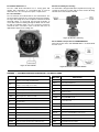
1
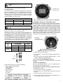
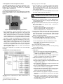
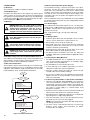
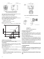
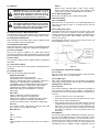
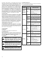
302-066
Installation & Operating Instructions
Series 3100 Differential Pressure Transmitter
SUPERSEDES: April 1, 2012
EFFECTIVE: August 1, 2012
2
Table of Contents
Page
Section 1.0
Introduction . . . . . . . . . . . . . . . . . . . . . . . . . . . . . . . . . . . . . . . . . . . . . . . . . . . . . . . . . . . . . . . . . . . . . . . . . . . 4
Using This Manual . . . . . . . . . . . . . . . . . . . . . . . . . . . . . . . . . . . . . . . . . . . . . . . . . . . . . . . . . . . . . . . . . . . . . . 4
Overview of Transmitter . . . . . . . . . . . . . . . . . . . . . . . . . . . . . . . . . . . . . . . . . . . . . . . . . . . . . . . . . . . . . . . . . 4
Software Compatibility . . . . . . . . . . . . . . . . . . . . . . . . . . . . . . . . . . . . . . . . . . . . . . . . . . . . . . . . . . . . . . . . . . 4
Section
Handling Cautions . . . . . . . . . . . . . . . . . . . . . . . . . . . . . . . . . . . . . . . . . . . . . . . . . . . . . . . . . . . . . . . . . . . . . . 4
Unpacking Transmitters and Specifications Check . . . . . . . . . . . . . . . . . . . . . . . . . . . . . . . . . . . . . . . . . . . 5
Models and Specifications Check . . . . . . . . . . . . . . . . . . . . . . . . . . . . . . . . . . . . . . . . . . . . . . . . . . . . . . . . . 5
Storage . . . . . . . . . . . . . . . . . . . . . . . . . . . . . . . . . . . . . . . . . . . . . . . . . . . . . . . . . . . . . . . . . . . . . . . . . . . . . . . 5
Selecting Installation Locations . . . . . . . . . . . . . . . . . . . . . . . . . . . . . . . . . . . . . . . . . . . . . . . . . . . . . . . . . . . 5
Calibration after Installation . . . . . . . . . . . . . . . . . . . . . . . . . . . . . . . . . . . . . . . . . . . . . . . . . . . . . . . . . . . . . . 5
Pressure Connections . . . . . . . . . . . . . . . . . . . . . . . . . . . . . . . . . . . . . . . . . . . . . . . . . . . . . . . . . . . . . . . . . . . 5
Waterproofing Cable Conduit Connections . . . . . . . . . . . . . . . . . . . . . . . . . . . . . . . . . . . . . . . . . . . . . . . . . 5
Restrictions on Use of Radio Transceiver . . . . . . . . . . . . . . . . . . . . . . . . . . . . . . . . . . . . . . . . . . . . . . . . . . . 5
Installation Resistance Test and Dielectric Strength Test . . . . . . . . . . . . . . . . . . . . . . . . . . . . . . . . . . . . . . 5
Explosion-Proof Transmitters . . . . . . . . . . . . . . . . . . . . . . . . . . . . . . . . . . . . . . . . . . . . . . . . . . . . . . . . . . . . . 6
EMC Conformity Standards . . . . . . . . . . . . . . . . . . . . . . . . . . . . . . . . . . . . . . . . . . . . . . . . . . . . . . . . . . . . . . 6
Section
Transmitter Functions . . . . . . . . . . . . . . . . . . . . . . . . . . . . . . . . . . . . . . . . . . . . . . . . . . . . . . . . . . . . . . . . . . . 6
Overview . . . . . . . . . . . . . . . . . . . . . . . . . . . . . . . . . . . . . . . . . . . . . . . . . . . . . . . . . . . . . . . . . . . . . . . . . . . . . . 6
Safety Messages . . . . . . . . . . . . . . . . . . . . . . . . . . . . . . . . . . . . . . . . . . . . . . . . . . . . . . . . . . . . . . . . . . . . . . . 6
Warning . . . . . . . . . . . . . . . . . . . . . . . . . . . . . . . . . . . . . . . . . . . . . . . . . . . . . . . . . . . . . . . . . . . . . . . . . . . . . . . 6
Fail Mode Alarm . . . . . . . . . . . . . . . . . . . . . . . . . . . . . . . . . . . . . . . . . . . . . . . . . . . . . . . . . . . . . . . . . . . . . . . . 7
EEProm-Write Enable/Disable Mode Jumper . . . . . . . . . . . . . . . . . . . . . . . . . . . . . . . . . . . . . . . . . . . . . . . . 7
Configuration of Alarm and Security Jumper Procedures . . . . . . . . . . . . . . . . . . . . . . . . . . . . . . . . . . . . . . 7
Configuration of Zero and Span Procedures . . . . . . . . . . . . . . . . . . . . . . . . . . . . . . . . . . . . . . . . . . . . . . . . 8
Commissioning on the Bench with HHT . . . . . . . . . . . . . . . . . . . . . . . . . . . . . . . . . . . . . . . . . . . . . . . . . . . . 9
Section
Installation . . . . . . . . . . . . . . . . . . . . . . . . . . . . . . . . . . . . . . . . . . . . . . . . . . . . . . . . . . . . . . . . . . . . . . . . . . . 10
Overview . . . . . . . . . . . . . . . . . . . . . . . . . . . . . . . . . . . . . . . . . . . . . . . . . . . . . . . . . . . . . . . . . . . . . . . . . . . . . 10
Safety Messages . . . . . . . . . . . . . . . . . . . . . . . . . . . . . . . . . . . . . . . . . . . . . . . . . . . . . . . . . . . . . . . . . . . . . . 10
Warning . . . . . . . . . . . . . . . . . . . . . . . . . . . . . . . . . . . . . . . . . . . . . . . . . . . . . . . . . . . . . . . . . . . . . . . . . . . . . 10
Commissioning on the Bench with Hand-Held Terminal . . . . . . . . . . . . . . . . . . . . . . . . . . . . . . . . . . . . . . 10
General Considerations . . . . . . . . . . . . . . . . . . . . . . . . . . . . . . . . . . . . . . . . . . . . . . . . . . . . . . . . . . . . . . . . . 10
Electrical Considerations (Power Supply) . . . . . . . . . . . . . . . . . . . . . . . . . . . . . . . . . . . . . . . . . . . . . . . . . . 10
Wiring . . . . . . . . . . . . . . . . . . . . . . . . . . . . . . . . . . . . . . . . . . . . . . . . . . . . . . . . . . . . . . . . . . . . . . . . . . . . . . . 10
Mechanical Considerations . . . . . . . . . . . . . . . . . . . . . . . . . . . . . . . . . . . . . . . . . . . . . . . . . . . . . . . . . . . . . 12
Environmental Considerations . . . . . . . . . . . . . . . . . . . . . . . . . . . . . . . . . . . . . . . . . . . . . . . . . . . . . . . . . . . 12
Section
On-line Operation . . . . . . . . . . . . . . . . . . . . . . . . . . . . . . . . . . . . . . . . . . . . . . . . . . . . . . . . . . . . . . . . . . . . . 12
Overview . . . . . . . . . . . . . . . . . . . . . . . . . . . . . . . . . . . . . . . . . . . . . . . . . . . . . . . . . . . . . . . . . . . . . . . . . . . . . 12
Safety Messages . . . . . . . . . . . . . . . . . . . . . . . . . . . . . . . . . . . . . . . . . . . . . . . . . . . . . . . . . . . . . . . . . . . . . . 12
Configuration Data Review . . . . . . . . . . . . . . . . . . . . . . . . . . . . . . . . . . . . . . . . . . . . . . . . . . . . . . . . . . . . . 13
Configuration Verification . . . . . . . . . . . . . . . . . . . . . . . . . . . . . . . . . . . . . . . . . . . . . . . . . . . . . . . . . . . . . . . 13
Basic Setup . . . . . . . . . . . . . . . . . . . . . . . . . . . . . . . . . . . . . . . . . . . . . . . . . . . . . . . . . . . . . . . . . . . . . . . . . . . 13
Detailed Setup . . . . . . . . . . . . . . . . . . . . . . . . . . . . . . . . . . . . . . . . . . . . . . . . . . . . . . . . . . . . . . . . . . . . . . . . 13
Configuration Variables Setup . . . . . . . . . . . . . . . . . . . . . . . . . . . . . . . . . . . . . . . . . . . . . . . . . . . . . . . . . . . 13
Diagnostics and Services . . . . . . . . . . . . . . . . . . . . . . . . . . . . . . . . . . . . . . . . . . . . . . . . . . . . . . . . . . . . . . . 13
Calibration . . . . . . . . . . . . . . . . . . . . . . . . . . . . . . . . . . . . . . . . . . . . . . . . . . . . . . . . . . . . . . . . . . . . . . . . . . . . 13
Section
Maintenance . . . . . . . . . . . . . . . . . . . . . . . . . . . . . . . . . . . . . . . . . . . . . . . . . . . . . . . . . . . . . . . . . . . . . . . . . 14
Overview . . . . . . . . . . . . . . . . . . . . . . . . . . . . . . . . . . . . . . . . . . . . . . . . . . . . . . . . . . . . . . . . . . . . . . . . . . . . . 14
Safety Messages . . . . . . . . . . . . . . . . . . . . . . . . . . . . . . . . . . . . . . . . . . . . . . . . . . . . . . . . . . . . . . . . . . . . . . 14
Hardware Diagnostics . . . . . . . . . . . . . . . . . . . . . . . . . . . . . . . . . . . . . . . . . . . . . . . . . . . . . . . . . . . . . . . . . 14
Hardware Maintenance . . . . . . . . . . . . . . . . . . . . . . . . . . . . . . . . . . . . . . . . . . . . . . . . . . . . . . . . . . . . . . . . . 15
Appendix 1 3100 Smart Pressure Transmitter LCD Display Code . . . . . . . . . . . . . . . . . . . . . . . . . . . . . . . . . . . . . . 15
1.1
1.2
1.3
2.0
2.1
2.2
2.3
2.4
2.5
2.6
2.7
2.8
2.9
2.10
2.11
3.0
3.1
3.2
3.3
3.4
3.5
3.6
3.7
3.8
4.0
4.1
4.2
4.3
4.4
4.5
4.6
4.7
4.8
4.9
5.0
5.1
5.2
5.3
5.4
5.5
5.6
5.7
5.8
5.9
6.0
6.1
6.2
6.3
6.4
3
1. INTRODUCTION:
1.3 Software Compatibility:
The 3100 Smart Pressure Transmitter is calibrated at the factory
before shipping. To ensure correct and efficient use of the instrument, please read the manual thoroughly and fully understand
how to operate the instrument before operation.
The Taco Smart Pressure Transmitter's software is implemented
at the factory. The following functions can be configured using a
HHT (Hart® Communicator).
The contents of this manual are subject to change without prior
notice.
All rights are reserved. No part of this manual may be reproduced
in any form without the written permission of Taco, Inc.
If any question arises, errors are found or if any information is
missing from this manual, please inform Taco, Inc.
The specifications covered by this manual are limited to standard
transmitters and do not cover custom-made instruments.
Please note that changes in the specifications, construction, or
component parts of the instrument may not immediately be
reflected in this manual at the time of change, provided that postponement of revisions will not cause difficulty to the user from a
functional or performance standpoint.
1.1 Using This Manual:
The operating manual provides information on installing, operating, and maintaining the Taco Model 3100 Smart Pressure
Transmitter. The sections are organized as follows:
Section 2 – Handling Cautions
Section 2 provides instructions on commissioning and operating the Model 3100 Smart Pressure Transmitters. Informations
on software functions, configuration parameters, and on-line
variables are also included.
Section 3 – Transmitter Functions
FUNCTION
ZERO/SPAN
Button
PC/PDA
HART
HHT
•
•
•
•
•
•
•
•
•
•
•
•
•
∆
Rev. 58
ZERO/SPAN
ZERO/TRIM
ZERO Adj
Units set
Range set
Dampening set
LCD decimal set
• – Supported
•
•
•
•
•
•
•
∆ – Supported but update required
2. HANDLING CAUTIONS:
This section consists of cautions for transmitter handling, storage,
installation, insulation and explosion structure, etc.
JOB
JOB DETAILS
Unpacking
• Unpack transmitter packing.
Model and
Specifications
• Make sure the transmitter nameplate
matches the model number on the P.O.
Storage
Section 4 contains mechanical, environment consideration and
electrical installation instructions for the Model 3100 Smart
Pressure Transmitter.
Section 5 – On-line Operation
• In a dry, non-vibration and non-impact
area.
• Ambient temperature around 77°F (25°C)
and 65% relative humidity.
Calibration
• Configuration of the Range, Zero/Span,
Unit, Tag, Dampening Time, Transfer
Function, DA Trim and other parameters.
Section 5 describes how to configure the parameters of the
Model 3100 Smart Pressure Transmitter. See the following list
for the details.
Section 3 contains suggestions on handling the Model 3100
Smart Pressure Transmitter.
Section 4 – Installation
1. Regulations for circuit's Input/Output characteristics; Sensor
or Output Trim
2. Changing the output characteristic; Range Configuration,
Output Type, Dampening, Unit
3. Changing the general data; Tag No., Date, Message etc.
Section 6 – Maintenance
Section 6 contains hardware diagnostics, troubleshooting and
maintenance tasks.
1.2 Overview of Transmitter:
The Taco Smart Pressure Transmitter is a microprocessor based
pressure transmitter with a capacitance sensor optimized for draft
measurement. The Model 3100 has a true draft analog range from
0 to 20 mA. This transmitter is explosion-proof, high precision
accuracy, reliability and has digital communication for remote
communication system.
The Model 3100 is enabled with HART® communication with Host,
HHT (HART® Communicator) or PC Configurator. The transmitter’s
various variables in host are able to be changed, configured and
calibrated by users. The HART® Communication between DC
power supply and transmitter requires a 250 - 550 Ohm resistance.
HART® is a registered Trademark of Hart
Communication Foundation.
4
FUNCTION SUPPORTS
INSTRUMENT
HHT
Pressure Source
Galvanometer
Installation
Locations
•
•
•
•
Where ambient temperature is constant.
Exposure to chemical corrosion, etc.
Where shock and vibration are minimal.
Where the area classification does not
exceed the explosion-proof rating.
• Where maintenance is easy.
(Engineering)
Mechanical
Considerations
• Where the transmitter can be handled easily.
• Be cautious of process connections leaking.
(Engineering)
Electrical
Considerations
• 24 VDC
(Power Supply is 11.9 VDC - 45 VDC).
• For HART® communication, resistance on
transmitter terminal loop should be
between 250 -550 ohms.
(Engineering)
Mounting and
Installation
• When mounting the transmitter, an appropriate bracket should be used.
• The transmitter should be mounted securely
to prevent swing.
(Mounting and
Installation)
Calibration on
Spot
• Sensor Zero Trim should be done ten seconds after differential pressure stabilizes.
• Make sure that PV value is zero and
current is 4 mA.
HHT or
Zero/Span
Button
Pressure
• Do not apply a regulated differential pressure and line pressure.
• Close the equalizing valve on the 3 valve
manifold and then open the valve on high
and low side slowly and simultaneously.
(Applying
Pressure)
Operation
• Make sure the instrument operates properly.
Eye or HHT
2.1 Unpacking Transmitters:
When moving the transmitter to the installation site, keep it in the
original packaging. Unpack the transmitter at the installation site
to avoid damage on the way.
2.2 Model and Specifications Check:
The model number and specifications are indicated on the nameplate. Please check the specification and model number.
2.3 Storage:
The following precautions must be observed when storing the
instrument, especially for a long period of time.
1. Select a storage area that meets the following conditions:
- is not exposed to rain or water
- minimal vibration and shock
- stored at normal temperature and humidity
(approx. 77°F (25°C), 65% RH)
The ambient temperature and relative humidity ratings are:
- Ambient Temperature:
-40 to 185°F (-40 to 85°C) (without LCD module)
-22 to 176°F (-30 to 80°C) (with LCD module)
- General Use: -4 to 140°F (-20 to 60°C)
- Relative Humidity: 5% - 98% RH at 104°F (40°C)
2. When storing the transmitter, repack it the way it was delivered
from the factory.
3. If storing a used transmitter, thoroughly clean the diaphragm
surfaces, so that no media remains. Make sure the transmitter
assemblies are securely mounted before storing.
2.4 Selecting Installation Locations:
The transmitter is designed to withstand severe environmental
conditions. However, to ensure stable and accurate operation, the
following precautions must be observed when selecting an installation location.
2.6 Pressure Connections:
CAUTION: Instrument installed in the process
under pressure. Never loosen or tighten as it may
cause dangerous spouting of process fluid. If the
process fluid is toxic or otherwise harmful, take
appropriate care to avoid contact or inhalation of
vapors even after disconnecting the instrument
from process line for maintenance.
The following precautions must be observed in order to safely
operate the transmitter under pressure.
1. Never apply a pressure higher than the specified maximum
working pressure.
2. Confirm the option pressure of transmitter. It is necessary to
use standardized and quality-approved parts.
3. There should be isolation valves in case of leakage.
2.7 Waterproofing Cable Conduit Connections:
Apply a non-hardening sealant (silicone or tape, etc.) to the
threads to waterproof the transmitter cable conduit connections.
2.8 Restrictions on Use of Radio Transceivers:
WARNING: Although the transmitter has been
designed to resist high frequency electrical noise,
if a radio transceiver is used near the transmitters
external wiring, the transmitter may be affected by
high frequency noise pickup. To test for such
effects, bring the transceiver in slowly from a distance of several feet from the transmitter, and
observe the measurement loop for noise effects.
Always use the transceiver outside the area affected by noise.
1. Ambient Temperature
Avoid locations subject to wide temperature variations or a significant temperature gradient. If the location is exposed to radiant heat from plant equipment, provide adequate insulation or
ventilation.
2.9 Installation Resistance Test and Dielectric Strength Test:
Since the transmitter has undergone insulation resistance and
dielectric strength tests at the factory, normally these tests are not
required. However, if required, observe the following precautions
in the test procedures.
2. Ambient Atmosphere
Avoid installing the transmitter in a corrosive atmosphere. If the
transmitter must be installed in a corrosive atmosphere, there
must be adequate ventilation. Precautions must be put into
place to prevent intrusion or stagnation of rainwater in conduits.
1. Do not perform such tests more frequently than necessary. Even
test voltages, that do not cause visible damage to the insulation,
may degrade the insulation and reduce safety margins.
3. Shock and Vibration
Select an installation site with minimum shock and vibration
(although the transmitter is designed to be relatively resistant to
shock and vibration).
4. Installation of Explosion-Proof Transmitters
Explosion-Proof transmitters can be installed in hazardous
areas according to the gas types for which they are certified.
5. Select a place where the transmitter can be maintained easily.
2.5 Calibration after Installation:
Sensor Zero Trim should be done after transmitter is installed,
because the zero point is not configured for mounting status.
When calibrating the Sensor Zero Trim apply a pressure for zero
in advance, Sensor Zero Trim the sensor when the pressure is sufficiently stabilized (after approximately 10 seconds).
There are two ways to pressure zero. One way is to apply zero differential pressure (making pressure the same on both the high and
low side). The other is to close High and Low side of a 3 valve
manifold and open the equalizing valve.
Sensor Zero Trimming can also be done with the Zero/Span button or a HHT (HART® Communicator), PC or PDA configurator.
Refer to On-line Operation for configuring other parameters.
2. Never apply a voltage exceeding 500VDC for the insulation
resistance test, or a voltage exceeding 500VAC for the dielectric strength test.
3. Before conducting these tests, disconnect all signal lines from
the transmitter terminals. Perform the tests in the following procedures.
2.9.1 Insulation Resistance test:
1. Short-circuit the + and - SUPPLY terminals in the terminal box.
2. Turn OFF the insulation tester. Then connect the insulation
tester plus (+) lead-wire to the shorted SUPPLY terminals and
the minus (-) lead wire to the grounding terminal.
3. Turn ON the insulation tester power and measure the insulation
resistance. The voltage should be applied briefly to verify that
insulation resistance is at least 20MΩ.
4. After completing the test and being very careful not to touch
exposed conductors, disconnect the insulation tester and connect a 100kW resistor between the grounding terminal and the
short-circuiting SUPPLY terminals. Leave this resistor connected at least three seconds to discharge any static potential. Do
not touch the terminal while it is discharging.
2.9.2 Dielectric Strength Test:
1. Short-circuit the + and - SUPPLY terminals in the terminal box.
2. Turn off the dielectric strength tester. Then connect the tester
between the shorted SUPPLY terminal and the grounding ter-
5
minal. Be sure to connect the grounding lead of the dielectric
strength tester to the ground terminal.
3. Set the current limit on the dielectric strength tester to 10 mA,
then turn on the power and gradually increase the tester voltage from ‘0’ to the specified voltage.
4. When the specified voltage is reached, hold it for one minute.
5. After completing this test, slowly decrease the voltage to avoid
any voltage surges.
2.10 Explosion-Proof Rating:
2.10.1 FM Certification:
HAZARDOUS LOCATION ELECTRICAL EQUIPMENT
• Equipment Rating: Explosion-Proof for use in Class I,
Division 1, Groups A, B, C and D
• Dust- Ignition-Proof for Class II/III, Division 1, Groups E, F
and G
• Nonincensive for use in Class I, Division 2, Groups A, B, C
and D
• Suitable for use in Class II, Division 2, Groups E, F and G
and Suitable for Class III, Division 1
• Hazardous (classified) location, indoor and outdoor (NEMA
Type 4X/IP67)
2.10.2 DEKRA/ATEX Certification:
• ATEX Certification number: DEKRA 11ATEX0192X
• CE 0344
II 2 G
NOTICE
3. Housing Ground must be followed to “local electrical codes”.
The most efficient ground procedure is to connect directly to
the earth as least impedance.
4. How to install Housing Ground:
• Internal Ground Connection – Internal ground connection
screw is located in terminal in housing. The screw can be
identified as ground sign.
• External Ground Assembly – This is located in the right side
of housing and identified by ground sign (grounding with a
cable lug).
5. When use tubing, stopping boxes must be connected with the
wall of housing directly.
6. Tubing is installed a minimum of 5 threads.
7. Sensor is to be threaded a minimum of 7 threads and prevented from turning by tightening the housing rotation set screw.
8. Do not disassemble flameproof joints but in an unavoidable
case to disassemble it or need the specification of flameproof
joints, contact the manufacturer before doing.
NOTICE
Operation
WARNING: Do not open when an explosive atmosphere may be present.
Take care not to generate mechanical spark when access to the
instrument and peripheral devices in hazardous location.
Model 3100 for Potentially Explosive Atmosphere
•
d IIC T6...T4
• Operating Temperature: -20°C ≤ Tamb ≤ +60°C
• T6 for process ≤ 85°C
• T5 for process ≤ 100°C
• T4 for process ≤ 130°C
NOTICE
Electrical Data
• Supply Voltage: 42 VDC Max
• Output Signal: 4 to 20 mA + HART
NOTICE
Electrical Connection
• 2 x 1⁄2-14 NPT Female
NOTICE
3100 ATEX Certification Standards
• EN 60079-0: 2006
• EN 60079-1: 2007
NOTICE
Installation
1. All wiring shall comply with local installation requirement.
2. The cable glands and blanking elements shall be of a certified
flameproof type, suitable for the condition of use and correctly
installed. Also those devices should be endured at the 130°C.
6
NOTICE
Maintenance and Repair
The instrument modification or parts replacement by other than
authorized representative of Taco, Inc. is prohibited and will void
KEMA/ATEX explosion-proof/flame-proof.
2.11 EMC Conformity Standards:
• EMI (Emission): EN55011
• EMS (Immunity): EN50082-2
Taco, Inc. recommends customer use metal conduit wiring or
twisted pair shield cable for signal wiring to conform with EMC
regulation when installing the Taco 3100 transmitters.
3. TRANSMITTER FUNCTIONS:
3.1 Overview:
This section contains information on operating the Model 3100.
Tasks that should be performed on the bench prior to installation
are explained in this section.
3.2 Safety Messages:
Procedures and instructions in this section may require special
precautions to ensure the safety of the personnel performing the
operations. Potential safety issues are indicated by a warning
symbol (
). Refer to the following safety messages before performing an operation preceded by this symbol.
3.3 Warning:
DANGER: Explosion can result in death or serious
injury.
Do not remove the transmitter covers in explosion environments
when the circuit is powered. Transmitter covers must be fully
engaged to meet explosion-proof requirements.
WARNING: Electrical shock can result in serious
injury.
Only qualified personnel can install the transmitter.
3.4 Fail Mode Alarm:
Fail Mode Select
Jumber Switch
Taco Smart Pressure Transmitter automatically and continuously
performs self-diagnostic test. If the self-diagnostic test detects a
failure, the transmitter drives the output outside of the normal
operation values. The transmitter will drive its output low (down)
or high (up) based on the position of the failure mode alarm
jumper. See Table 1 for output values.
Table 1: STANDARD ALARM AND SATURATION VALUES
LEVEL
4-20 mA SATURATION
3.9 mA
≤ 3.75 mA
20.87 mA
≥ 21.75 mA
Low/Down
High/Up
4-20 mA ALARM
WARNING: Electrical shock can result in serious
injury.
Avoid contact with the leads and terminals. High voltage, that may
be present on leads can cause electrical shock.
Fail Safe mode can be set via Jumper switches provided on the
LCD module or the main CPU module. The jumper switch for an
indicating transmitter, located on the LCD module, can be set to
the right (fail down, i.e. ≤ 3.75 mA) or left (fail up, i.e. ≥ 21.75 mA).
For non-indicating transmitters the jumper switch is located on
the main CPU module. It can be set up (fail up to ≥ 21.75 mA) or
down (fail down to ≤ 3.75 mA). Refer to Table 2 for detailed summary of jumper settings for both CPU and LCD modules.
Figure 3: Fail Mode Selection Jumper Switch for LCD Module
3.5 EEPROM - Write Enable / Disable Mode Switch:
EEPROM (Electrically Erasable Programmable ROM), included on
the CPU module, is used by the transmitter to save/restore configuration variables. To protect the transmitter from any unauthorized changes, a hardware lockout feature can be implemented by
using the Write-Protect mode jumper switch provided on the main
CPU Module. If the jumper switch is connected to DIS, this disables writing/changing of any data saved in the EEPROM. On the
other hand, if the jumper switch is set to “EN”, changes can be
made to the configuration data stored in the EEPROM. The factory
default setting is “EN” (Enable) for all transmitters. The location of
the Wire Protect Jumper Switch can be seen in Figure 4.
CPU Module
Jumber Switch
1) Fail Mode Selection
Table 2: CPU and LCD MODULE JUMPER SETTINGS
Both LCD Module
and CPU Module
Only CPU
Module
Select
Fail
Mode
CPU Module
LCD Module
CPU Module
Fail Down
Down
D
D
Down
U
Up
U or D
Fail Up
U
Figure 4: CPU Module Fail Mode
EEPROM - Write Selection Jumper Switch
The 3100 has two security settings.
1. Security Jumper - the transmitter configuration parameters are
protected.
2. Physically removing Zero and Span Magnetic Buttons - you are
unable to regulate zero and span locally.
Figure 1
Fail Safe Mode Selection (LCD and CPU Module)
1. WR_EN (EEPROM Write Enable)
DOWN: ENABLE
UP: DISABLE
2. Fail Mode (Alarm)
DOWN: LOW
UP: HIGH
3.5.1 Security Jumper (EEPROM Write Protect):
Prevents the transmitter’s configured parameters from being
changed.
3.5.2 Zero and Span Buttons:
By removing the Magnetic Buttons, you can’t configure the transmitter using the Zero and Span locally.
3.6 Configuration of Alarm and Security Jumper Procedures:
Changing jumper position:
1. If the transmitter is installed, cutoff power.
2. Open the front cover. If the transmitter is powered, don’t open
the cover.
3. Move the jumper to the preferred position.
4. Close the front housing covers. You must fully engage the cover
to meet explosion-proof requirements.
Figure 2: Fail Mode and EEPROM - Write Selection Jumper Switch
7
3.7 Configuration of Zero and Span Procedures:
The ZERO and SPAN Buttons are under the transmitter’s nameplate. The ZERO, SPAN, ZERO TRIM, ZERO ADJ, Units, Range,
Dampening, LCD and decimal set functions are configurable
using the ZERO / SPAN buttons.
3.7.1 Zero/Span Configuration Process:
Remove both nameplate screws on the upper part of transmitter.
Remove top nameplate to access the Zero and Span Buttons (see
Figure 5).
3. Moving to top menu: Zero+Span
• Press the button for 3 seconds to execute each function.
After 3 seconds press the Zero+Span buttons, the LCD display will change from Menu to Trim. To see the next menu,
press the Zero button for 3 seconds. Use the Zero button to
move down the directory.
• Use the Span button to select the displayed menu. The same
procedure will be used for the sub menus.
CAUTION: After 30 seconds without any action,
the button function will return to normal operation.
Zero/Span
Buttons
4. How to select a numerical value
(a) Functions use numerical values: 12 Zero Adjustment, 22
Change Upper Range Value, 23 Change Lower Range Value,
24 Dampening Second
Figure 5: Transmitter Zero/Span Configuration Buttons
1. Zero Configurations – Set the current process value for Lower
Range Value (4 mA). Apply zero pressure for 10 seconds and
push the Zero Button for 5 seconds. The LCD should display
“Zero”. Push the Zero button for 3 seconds, after 1 second the
LCD should display “-ZE-”. This message means the zero configuration is finished. If the zero configuration failed, the LCD will display “SPEr” or “SEtE”, try repeating the zero configuration steps.
2. Span Configurations – Apply the desired pressure for 10 seconds and push the Span Button for 5 seconds. The LCD should
display “Span”. Push the Span button for 3 seconds, after 1
second the LCD should display “-SP-”. This message means
that the span configuration is finished. If the span configuration
failed the LCD will display “SPEr” or “SEtE”, try repeating the
span configuration steps.
Please refer to Appendix 1 for the button error and LCD display
message.
3.7.2 Menu Tree for Zero+Span Function:
(b)How to select numerical value: First, select an increasing rate
(10n), then change each decimal value to increase or
decrease as wanted.
For example, select 3810:
Select increasing rate 1000 -> Increase 3 times ->
Select increasing rate 100 -> Increase 8 times ->
Select increasing rate as 10 -> Increase 1 time
(c) To select the increase / decrease steps: SelInc message will
be displayed on the bottom of the LCD. Select parameter and
press the Zero button : The decimal value will be changed
when the Zero button is pressed. After set, press the span
button to execute the parameter.
(d)To set the required values using Zero/Span buttons: VALUE
message will be displayed on the bottom of the LCD.
1. Press the Zero button, the menu will increase 1 item.
2. Press the Span button, the menu will decrease 1 item.
3. After setting, save the parameter by pressing the
Zero+Span buttons.
(e) To set the final value, repeat (c) and (d).
(f) After setting the final parameter, exit the menu by pressing
the Zero+Span buttons.
5. Exercises for each function
• ZERO TRIM
1. Access the menu by pressing the Zero+Span buttons.
2. Move to the sub directory using the Span button until the
1 TRIM message appears on the display.
3. Change the Zero Trim Function by using the Span button
until the 11 Z-TRIM message appears on the display.
• ZERO ADJUSTMENT: Change the PV value to 14
1. Exit the menu by pressing the Zero+Span button.
2. Move through the sub directory using the Span button until
1 TRIM message appears.
3. Move through the sub directory using the Zero button until
11 Z-TRIM message appears.
4. Access the Zero Adjustment function by pressing the Span
button until the 12 Z-ADJ message appears.
5. When the SelInc message appears, press the Zero button
repetitively until the 10.0 message appears on the LCD.
Set the value by pressing the Span button.
6. When VALUE message appears, change the LCD value to
10.0 and press the Zero button, then press the Zero+Span
buttons.
The other functions supported by the ZERO / SPAN Buttons are
as follows:
1. Moving between menus: Zero
2. Enter or moving to sub menu: Span
8
7. When Sellnc message appears, change the LCD value to
1.0 and press the Zero button, then set the value and press
the Span button. Press the Zero+Span buttons after the
LCD value changes to 14.0.
8. To save the settings, press the Zero+Span buttons until the
SelInc message appears.
• CHANGE UNITS
1. Access the menu by pressing the Zero+Span buttons.
2. Move to next menu by pressing the Zero button until the
1 TRIM message appears.
3. Moving thru the sub directory press the Span button until
the 2 SETUP message appears.
4. Press the Span button to access 21 UNIT, press Span
again to access Change Unit.
5. Save the values by pressing the Span button when the
desired value is displayed on the LCD.
• CHANGE UPPER RANGE VALUE
1. Access the menu by pressing the Zero+Span buttons.
2. Move to next menu by pressing the Zero button until the
1 TRIM message appears.
3. Press the Span button until the 2 SETUP message
appears.
4. Press the Span button until the 21 Unit message appears.
5. Press the Zero button until the 22 U-RNG message
appears.
6. Press the Span button until the Zero Adjustment message
appears.
• CHANGE LOWER RANGE VALUE
1. Access the menu by pressing the Zero+Span buttons.
2. Move to next menu by pressing the Zero button until the
1 TRIM message appears.
3. Press the Span button until the 2 SETUP message appears.
4. Press the Span button until the 21 Unit message appears.
5. Press the Zero button until the 22 U-RNG message
appears.
6. Press the Zero button until the 23 L-RNG message
appears.
7. Press the Span button until the Change Lower Range
Value message appears.
• CHANGE LCD MODE (Cyclic or Fixed Display)
3. Press the Span button until the 2 SETUP message appears.
4. Press the Span button until the 3 LCD message appears.
5. Press the Span button until the 31 DEC-PL message
appears.
6. Press the Span button until the Decimal Place message
appears. The decimal place will appear on the second line
of the LCD as follows:
DISPLAY
EXPLANATION
MAX.
VALUE
AUTO
Target value will be displayed automatically
99999
5-0
No decimal place
99999
4-1
Display one decimal place
9999.9
3-2
Display two decimal places
999.99
2-3
Display three decimal places
99.999
1-4
Display four decimal places
9.9999
7. The first line on the LCD will display 0.0.
8. The Decimal Place can be changed by pressing the Zero
button. Save the setting by pressing the Span button after
the decimal place has been selected.
9. The set value will display the PV value and Engineering
value.
10. The LCD will display LCD_OV and the saved Unit when the
pressure is over or under a set value.
3.8 Commissioning on the Bench with HHT:
The 3100 Pressure Transmitter can be commissioned using an
HHT before or after installation.
Connect an HHT (HART® HANDHELD Communicator) across the
COMM pins for HART® communication. The TEST pin connections can be used for connecting a multimeter to measure the output current directly from the transmitter. Since the 3100 is a two
wire loop powered transmitter, it requires an external loop power
supply (11.9V to 45VDC) to enable HART® communication. Any
HART® communication via HHT (or PC based configurator)
requires a minimum 250 - 550 (max) ohm loop resistance.
POWER/SIGNAL CONNECTIONS
1. Enter programming menu by pushing both (ZERO+SPAN)
button together for 5 seconds. Release buttons when LCD
displays Menu and display will automatically change to
“1 TRIM” confirming access into programming menu.
2. Push (ZERO) button when “1 TRIM” message appears on
LCD. Release button when display changes to “2 SETUP”.
3. Push (Zero) button and release when display changes to
“3 LCD”.
4. To move into sub directory push (Span) button after
“3 LCD” message appears on display. Release button
when 31 LCDMD message is displayed.
5. To enter this sub-menu, push (Span) button and release
when display changes to 311. Bottom line of display will
show current Mode setting (e.g. NOR-RO, NOR-PV. etc).
6. Push (Zero) button to cycle through available mode
options and select desired LCD rotation mode. Options are
NOR-RO (rotate all PV, %, mA), NOR-PV (fixed PV),
NOR-% (fixed %), NOR-mA fixed, ENG-RO, ENG-PV,
ENG-% or ENG-mA
7. Push (Span) to save changes and EXIT programming
mode.
• DECIMAL PLACE
1. Access the menu by pressing the Zero+Span buttons.
2. Move to next menu by pressing the Zero button until the
1 TRIM message appears.
1. HHT (HART Communicator) or PC Configurator may be connected at any terminal point in the signal loop.
2. HART Communication requires a loop resistance between 250 and 550 ohm
(24 VDC).
3. Transmitters operate on 11.9 to 45.0 VDC terminal voltage.
Applied Power:
• 11.9 - 45.0 VDC for general operation
• 17.4 - 45.0 VDC for HART Communication
Figure 6: Connecting the Transmitter to HHT
9
4. INSTALLATION:
4.6 Electrical Considerations (Power Supply):
4.1 Overview:
The information in Chapter 4 explains installation.
The transmitter housing is composed of two parts. One side is
electronics, and the other side is terminal block. The terminal
block side is the transmitter’s front side and is labeled “Field
Terminal” on the housing. The terminal block can be accessed by
removing the front cover. When wiring the power supply to the
transmitter make sure the positive and negative wires are connected correctly.
A HHT configurator can be connected directly across the (COMM)
pin terminal located just below the power supply (PWR) terminal
block connections.
4.6.1 Power Supply:
4.2 Safety Messages:
Procedures and instructions in this chapter may require special
safety measures to ensure the safety of the personnel performing
the operation. Potential installation safety issues are indicated by
a safety alert symbol (
). Refer to the following safety messages
before installing the 3100 pressure transmitter.
4.3 Warning:
DANGER: Explosion can result in death or serious
injury. Do not remove the transmitter covers in an
explosion-proof environment when the circuit is
powered. Both transmitter covers must be fully
engaged to meet the explosion-proof requirements.
WARNING: Electrical shock can result in serious
injury. Only qualified personnel can wire the pressure transmitter.
WARNING: Process leaks can cause death or
serious injury. Install and tighten before applying
pressure. If you don’t, it can cause process leaks.
DANGER: Electrical shock can result in death or
serious injury. Avoid contact with the leads and
terminals.
4.4 Commissioning on the Bench with Hand-Held Terminal:
The 3100 Pressure Transmitter can be commissioned before and
after installation. Commissioning is easier if the transmitter is configured on a bench with an HHT before installation.
4.5 General Considerations:
The transmitter can be mounted near the process to minimize piping. Keep in mind that easy access is required for personnel, field
calibration, and installation. Install the transmitter in an area with
minimal vibration, shock, and temperature fluctuations.
START
DO YOU WANT
VERIFY
A) PRESSURE SUPPORT
DO YOU
SATISFY SPEC
MAINTENANCE
FIELD INSTALL
A) JUMPER/SWITCH SETUP
B) TRANSMITTER TAKES UP
C) TRANSMITTER LEADS
D) TRANSMITTER FOR POWER SUPPLY
END
Figure 7: Installation Flow Chart
10
Max. Loop Resistance [Ω] = (E-11.9) [vdc] / 0.022 [mA]
4.7 Wiring:
4.7.1 Wiring Caution:
1. Install the signal cables away from potential sources of electrical noise such as transformers, electrical motors, etc.
2. Before wiring, remove electrical conduit cap.
3. All screwed connections on the housing must be sealed with
waterproof sealant. We recommend use of silicone based
sealants to minimize post-hardening.
4. Avoid running DC signal and AC power cables in the same
ducts/cable conduits to avoid signal noise issues.
5. All explosion-proof transmitters must meet the wiring and
installation requirements specified within the applicable electrical codes.
4.7.2 Selecting the Wiring Materials:
1. Use 600V shielded PVC wire or standard wire of the same
class. (To ensure proper communication use 24 AWG or larger
wire, and do not exceed 5000 feet)
2. Use shielded wire in areas with electrical noise.
3. In areas with high or low ambient temperatures, use wire or
cable that is rated for the extreme temperatures.
4. If the wire or cable is going to be used in oil, solvent, toxic gas
or liquid, make sure it is rated accordingly.
5. Process wire or cable must not be soldered to the terminal lug.
Spade connectors are recommended to connect the process
wires to the transmitter.
4.7.3 Connecting External Wires to Transmitter Terminal Box:
1. Open the cover indicated "FIELD TERMINAL". Do not open the
cover if the transmitter is located in an explosion-proof area
and powered. Connect the power supply to the terminal indicated "+PWR"(left terminal) and "-" in the central terminal. Do
not connect "+" power supply to "+" terminal "TEST". It will
damage the test diode.
YES
BASIC SETUP
A) UNIT SETUP
B) RANGE SETUP
C) DAMPENING SETUP
D) TRANSMITTER FUNCTION SETUP
NO
The 3100 Pressure Transmitter requires an 11.9 – 45 VDC power
supply. A 250 ~ 550Ω (24 VDC) loop resistance is recommended
for HART® communication. Loop resistance is the sum of the
resistance in the loop.
2. Seal and close the conduit connection to prevent humidity and
explosion-proof atmosphere from entering the housing.
3. Transmitter power is supplied by signal wire. Do not install near
high voltage wires or high voltage equipment.
4. Close the transmitter cover. To meet the explosion-proof ratings make sure the covers are fully engaged.
NOTE: Do not power the transmitter with high voltage (AC). It
can damage the transmitter.
5. You must connect a 250~550 Ohm Resistor in Current Loop
(between Power Supply and Transmitter) for HART®
Communication. See Figure 8.
4.7.4.2 Wiring Installation:
General use (see Figure 11):
Use metallic conduit or waterproof cable glands for wiring.
Apply non-hardening sealant to the terminal box and the threads
on the flexible metal conduit for waterproofing.
COMM
TEST
Figure 8: Wiring the 3100 Pressure Transmitter
Figure 11: Typical Mounting using Flexible Metal Conduit
Explosion-proof metal conduit wiring (see Figure 12):
A seal fitting must be installed near the terminal box port.
Figure 9: Picture of Transmitter Wiring Terminal
Apply a non-hardening sealant to the threads of the terminal connection box.
4.7.4 Wiring (Loop Configuration):
DANGER: Explosion can result in death or serious
injury. Do not remove the transmitter covers in an
explosion-proof environment when the circuit is
powered. Both transmitter covers must be fully
engaged to meet explosion-proof requirements.
4.7.4.1 Loop Configuration:
The Taco 3100 Pressure Transmitters use a two-wire system for
power, 4~20mA analog signal transmission and HART® digital
transmission.
A DC Power Supply is required for the transmitter loop. The transmitter and power supply should be connected as shown below.
See Figure 10.
Flameproof
heavy gauge
steel conduit
Apply a nonhardening sealant
to the threads
of these fittings
for waterproofing.
Figure 12: Typical Wiring using Explosion-Proof Conduit
COMM
TEST
11.9 - 45 VDC
Figure 10
4.7.5 Grounding:
Grounding should satisfy KS requirements (grounding resistance
should be 10 ohm or less). Grounding is required for explosionproof applications and the ground resistance must be below 10
ohms.
NOTE: In case of Built-in Lightning Protector, Grounding should
satisfy Special KS requirements (grounding resistance, 10 ohm or
less).
11
Figure 13: 3100 Smart Pressure Transmitter
Internal and External Ground Terminal
There are ground terminals on the inside and outside of the transmitter. Either of these terminals may be used.
Use 600V insulated PVC wire for grounding.
4.7.6 Power Supply Voltage and Load Resistance:
Figure 15: Model 3100 Outline Dimension Drawing
When configuring the loop, make sure that the external load resistance is within the range (see Figure 14 below).
The transmitter supply voltage should be:
• Standard: 11.9 to 45 Vdc
• HART Communication: 17.4 to 45 Vdc
Maximum loop current is 24mA.
Load resistance R = (E-11.9) / 0.022 (E = Power Supply Voltage)
Figure 16: A-630 Mounting Bracket
R=(E-11.9)/0.022
4.9 Environmental Considerations:
HART Communication
Applicable Range
Figure 14
4.8 Mechanical Considerations:
Figure 15 is a dimensional drawing for the 3100. Figure 16 shows
how the A-630 angle bracket is mounted to a pipe.
4.8.1 Mounting:
Avoid installing transmitters in environments with excessive vibration. If it cannot be avoided it is highly recommended to provide
adequate support when mounting.
4.8.2 Transmitter Access:
When selecting the installation location, accessibility must be
taken into consideration.
• Housing rotation: The housing can be rotated 90°.
• Wiring terminals: The cover and wiring terminals are easily
accessible.
• LCD/Circuits: Install the transmitter in a location where it can
be seen. For transmitters without an LCD, the cover and
jumpers are easily accessible.
12
4.9.1 Ambient Temperature:
The transmitter ambient temperature range is 4 to 180°F (-20 to
60°C). If the ambient temperature is going to exceed the temperature range, precautions must be taken to keep the temperature
within the temperature limits.
4.9.2 Toxic and Moist Environments:
The 3100 housing will protect the transmitter against moisture or
toxic material. The electronic circuit is separated from the terminals. The housing covers have o-rings that seal the housing, but
moisture can penetrate the housing through the conduit. The
transmitter should be mounted in a position to prevent moisture
from entering the housing through the conduit.
4.9.3 Installation in Hazardous Location:
The transmitter is designed with an explosion-proof housing.
Installation environment must not exceed the explosion-proof rating.
5. ON-LINE OPERATION:
5.1 Overview:
This chapter describes how to configure the 3100 Smart Pressure
Transmitter. The transmitter can be configured in On-Line or OffLine mode. In On-Line Mode a compatible HHT or PC configuration device must be used.
5.2 Safety Messages:
For added operator safety please pay specific attention to procedures outlined in this manual listed under the warning symbol
(
).
5.2.1 Warning:
DANGER: Explosion can result in death or serious
injury. Do not remove the transmitter covers in
explosion-proof environments when the circuit is
powered. Both transmitter covers must be fully
engaged to meet explosion-proof requirements.
DANGER: Electrical shock can result in serious
injury. When installing transmitters in close proximity of high voltage sources (near power lines) the
transmitter leads can be subject to high voltages.
Avoid contact with the leads and terminals.
5.2.2 Current to Passive Mode Configuration:
For multi-drop mode the current output must be configured as passive mode. Please disregard any other messages shown on HHT.
5.3 Configuration Data Review:
Before operating the transmitter make sure the configuration data
on the nameplate matches the application.
5.4 Configuration Verification:
Volume Gallons, liters, imperial gallons, cubic meters, barrels,
bushels, cubic yards, cubic feet, cubic inches, bbl liq, normal
cubic meter, normal liter, standard cubic feet, hectoliters
5.5.3 4-20mA Configuration:
Set the Zero and Span for the 4~20mA analog output.
5.6 Detailed Setup:
5.6.1 Set Fail Mode:
When the sensor or microprocessor is not operating properly, the
transmitter will output 3.75mA or 21.75mA based on the Fail
Mode setting.
5.6.2 Set Dampening Time:
The Dampening Seconds value changes the response time of the
transmitter to smooth out variations caused by rapid process
changes. Determine the appropriate dampening setting based on
the required response time, signal stability, and other requirements of your system.
The Dampening Seconds can be set from 0-60 seconds; the
default dampening value is 1.0 second.
Before the transmitter is ready for service, the configuration must be
checked to confirm the settings are configured for the application.
5.4.1 Process Variable:
There are two process variables in the 3100 Smart Pressure
Transmitter. The primary variable and temperature compensated SV
(Second Variable), the PV value outputs the 4~20mA analog value.
5.5 Basic Setup:
The correlation variable must be configured before operating the
transmitter.
5.5.1 Select Sensor Range:
Figure 17
The pressure range must be selected when ordering the pressure
transmitter.
5.5.2 Set Output Units:
Select from the following engineering units:
Volumetric Flow Unit CubicFeet/min, Gallons/min, Liters/min,
ImperialGallons/min, CubicMeter/hr, Ft/s, meters/s,
Gallons/s, mGallons/day, Liters/s, mLiters/day, CubicFeet/s,
CubicMeter/s, CubicMeter/day, ImperialGallons/hr,
ImperialGallons/day, NormalCubicMeter/hr, NormalLiter/hr,
StandardCubicFeet/min, CubicFeet/hr, CubicFeet/day,
CubicMeters/min, Barrels/s, Barrels/min, Barrels/hr,
Barrels/day, Gallons/hr, ImperialGallons/s, Liters/hr,
Gallons/day
Mass Flow Grams/s, Grams/min, Grams/hr, Kilograms/s,
Kilograms/min, Kilograms/hr, Kilograms/day,
MetricTons/min, MetricTons/hr, MetricTons/day, Pounds/s,
Pounds/min, Pounds/hr, Pounds/day, ShortTons/min,
ShortTons/hr, ShortTons/day, LongTons/hr, LongTons/day
Pressure kPa, mmH2O, InH2O, InHg, FtH2O, mmHg, psi, bar, mbar,
g/cm2, Kg/cm2, Pascals, MPa, torr, ATM
Miscellaneous %
Time Min, sec, hr, days
Mass Grams, kilograms, metric tons, pounds, short tons, long tons,
ounce
5.7 Configuration of Information Variable:
5.7.1 Set Tag:
Tags are an easy way to classify transmitters in multi transmitter
application. Tags can use 8 words/numbers.
5.7.2 Set Messages:
When using several transmitters, the user can define each transmitter by using 32 words/numbers. This message is saved in EEPROM.
5.8 Diagnostics and Service:
5.8.1 Loop Test:
The Loop Test verifies the output of the transmitter, the integrity of
the loop, and the operations of any recorders or similar devices
installed in the loop. The following procedures are required for a
loop test.
• Connect a reference meter to the transmitter.
• Select the Loop Test on the HHT and operate the Loop Test.
• Select current output (4mA/20mA/etc.)
• If the readings match, then the transmitter and the loop are
configured and functioning properly. If the readings do not
match, then you may have the current meter attached to the
wrong loop, there may be a fault in the wiring, the transmitter
may require an output trim, or the current meter may be malfunctioning.
5.9 Calibration:
The scale is implemented by calibrating the transmitter. Trim function has several calibration functions. Smart transmitters operate
differently than analog transmitter. A smart transmitter uses a
microprocessor that contains information about the sensor's specific characteristics in response to pressure and temperature for
calculating the process variable. 4-20mA configuration sets the
13
transmitter’s analog output to a selected upper and lower range
and can be done with or without an applied pressure. 4-20mA
configuration does not change the factory characterization curve
stored in the microprocessor. Sensor trimming requires an accurate pressure input and adds additional compensation that
adjusts the factory characterization curve to optimize transmitter
performance over a specific pressure range. 4-20mA configuration provides the ability to readjust the 4~20mA sensor inputs
without an applied pressure. Reranging does not change the factory or characterization curve stored in the microprocessor.
Sensor trimming requires an accurate pressure input and adds additional compensation to the factory characterization curve to optimize
transmitter performance over a specific pressure range. Rerange
provides ability to readjust the 4~20 mA points sensor inputs.
6.3 Hardware Diagnostics:
If there is a failure despite a diagnostic message on the HHT, Table
6.1 can help troubleshoot the problem.
TABLE 8.1
SYMPTOM
Transmitter
does not
Communicate
with HART®
Communicator
POTENTIAL
SOURCE
Check for a 250-550 ohm resistance
between the power supply and HHT.
Loop
Wiring
High Output
5.9.2 D/A (Digital to Analog) Trim:
The D/A trim function makes minor adjustments to the analog
(4- 20mA) output scaling from the transmitter. It is recommended
to do a D/A trim on both hi (20mA) & low (4mA) values for best
results. This function corrects any minuscule offsets within the
D/A conversion of the transmitter.
Sensor
Input
Failure
Connect HHT and enter the transmitter
test mode to isolate a sensor failure.
Loop
Wiring
Check for dirty or defective terminals,
interconnecting pins or receptacles.
Power
Supply
Check the output voltage of the power
supply at the transmitter terminals. It
should be 11.9 to 45 VDC.
Electronics
Module
Connect HHT and enter the transmitter
test mode to isolate module failure.
Check the sensor limits to ensure the
calibration adjustments are within the
sensor range.
Check the output voltage of the power
supply at the transmitter terminals. It
should be 11.9 to 45 VDC.
Loop
Wiring
6. MAINTENANCE:
6.1 Overview:
This chapter describes diagnostic and maintenance.
Erratic Output
6.2 Safety Messages:
When the transmitter is in operation, operators should follow all
safety messages. Potential safety issues are indicated by a safety
alert symbol (
). Refer to the following safety messages before
performing any operation proceeded by a (
) symbol.
Check for intermittent shorts, open circuits and multiple grounds.
Check for proper polarity at the signal
terminals.
Electronics
Module
Sensor
Element
6.2.1 Warning:
DANGER: Explosion can result in death or serious
injury. Do not remove the transmitter covers in
explosion-proof environments when the circuit is
powered. Both transmitter covers must be fully
engaged to meet explosion-proof requirements.
Check for adequate voltage to the
transmitter (the transmitter requires
11.9-45 VDC).
Check for intermittent shorts, open circuits and multiple grounds.
5.9.1 Sensor Trim:
The Sensor trim function adjusts the A/D signal conversion within
the transmitter sensor electronics and determines how it digitally
interprets any pressure changes applied to the sensor inputs. It is
highly recommended to perform a sensor trim when first commissioning the transmitter on site. There are three ways to trim the
sensor: Sensor zero trim, full trim and zero adjustment. Sensor
zero trim is a one-point adjustment typically used to compensate
for the mounting position. Two point trim is a full sensor trim, in
which two accurate pressures are applied (equal to or greater than
the range values), and the output is linear. You should always
adjust the low trim value first to establish the correct offset.
CORRECTIVE ACTION
Connect HHT and enter the transmitter
test mode to isolate an electronics
mode failure.
Connect HHT and enter the transmitter
test mode to isolate a sensor failure.
Is the PV out of range?
Check for adequate voltage to the
transmitter (the transmitter requires
11.9-45 VDC).
Low Output
or No Signal
Loop
Wiring
Check for intermittent shorts, open circuits and multiple grounds.
Check polarity of signal terminal.
Check the loop impedence.
DANGER: Electrical shock can result in serious
injury. When installing transmitters in close proximity of high voltage sources (near power lines) the
transmitter leads can be subject to high voltages.
Avoid contact with the leads and terminals.
WARNING: Electrical shock can result in death or
serious injury. Only qualified personnel can configure and wire the 3100 Smart Pressure Transmitter.
14
Electronics
Module
Connect HHT and check the sensor
limits to ensure the calibration adjustments are within the sensor range.
6.4 Hardware Maintenance:
6.4.2 Disassembling the Housing:
The Taco 3100 Smart Transmitter has no moving parts and
requires little maintenance. If a transmitter fails, it must be
returned to Taco, Inc. for inspection, repair, or replacement.
6.4.1 Test Terminals:
The transmitter is designed with dual-compartment housing; one
contains the electronics module, and the other contains all wiring
terminals and communication terminal.
The test terminals are marked TEST on the terminal block. The
test and negative terminals are connected to the power terminals.
So long as the voltage across the receptacles are below the diode
threshold voltage, no current will pass through the diode. To
ensure that current isn’t leaking through the diode, test the reading with an indicating meter. The test connection should not
exceed 10 ohms. A resistance value of 30 ohms will cause an
approximate 10 percent of reading error.
Figure 19: Structure of Housing
6.4.3 Fail Mode Jumper Switch and EEPROM-Write:
Fail-mode jumper switch and EEPROM-Write is located behind
the front cover.
Figure 18: Test Terminals
Figure 20: Structure of Electronics Module
APPENDIX 1 – 3100 SMART PRESSURE TRANSMITTER - LCD DISPLAY CODE:
MESSAGE
DESCRIPTION
MESSAGE
DESCRIPTION
ADJ-U
Zero adjustment value – used to configure transmitter
when it is out of range (on higher side)
SCD-ER
Sensor Code Error
Zero adjustment value – used to configure transmitter
when it is out of range (on low side)
F-RST
Flash Setting Data Reset
ADJ-L
F-LOCK
Flash Setting Data Reset, Protect Locked
ZERO
Initial message when using Zero button
F-FAIL
Flash Setting Data Reset Failure
SPAN
Initial message when using Span button
-FR-
Flash Reset done
BT-ERR
Button Sequence error
A-RST
Analog EEPROM Initializing Start
P-LOCK
Button input error - Protect Locked
A-STOR
Analog EEPROM Stored
ZT-ERR
Zero Trim value is over limit (10%)
A-FAIL
-TR-
Zero Trim done
Failure in writing configuration values on to the EEPROM
of transmitter CPU
ZR-ERR
Setting Limit error when executing Zero button function
-AC-
Analog EEPROM Configuration done
SP-ERR
Setting Limit error when executing Span button function
S-FL
Sensor Fail
-ZR-
Zero button function done
S-OP
Sensor Overpressure
-SP-
Span button function done
AEP-RF
Check error with EEPROM on CPU board
-ZA-
Zero Adjustment done
TS-FL
Temperature Sensor Error
DONE
Configuration completed using buttons
AEP-WF
Analog EEPROM write fail
RNGOVR
Limit error when executing other setting function
EOSC
Crystal Element Defect Alarm
LCD_OV
Over Values for LCD
FAVE
Flash Acess Violation
15
Printed in USA
TACO, INC., 1160 Cranston Street, Cranston, RI 02920 Telephone: (401) 942-8000 FAX: (401) 942-2360.
TACO (Canada), Ltd., 8450 Lawson Road, Unit #3, Milton, Ontario L9T 0J8. Telephone: 905/564-9422. FAX: 905/564-9436.
Visit our web site at: http://www.taco-hvac.com
16
Copyright 2012
TACO, Inc.