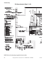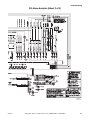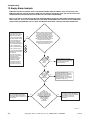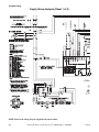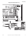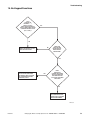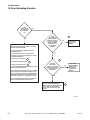
1
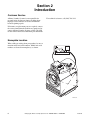
Troubleshooting
Washer-Extractor
Pocket Hardmount
UWAV and UWB2
Refer to Page 5 for Model Numbers
WARNING
MACHINE MAY BE HOT
AND CAUSE BURNS
ATTEMPT NO ENTRY
UNTIL
BASKET HAS STOPPED
SERIOUS INJURY MAY
RESULT
PHM1393C
www.comlaundry.com
Part No. F232218R1
July 2008
Table of
Contents
Section 1 – Safety Information ...............................................................2
General Safety Precautions....................................................................2
Important Safety Instructions ................................................................3
Locating an Authorized Servicer...........................................................5
Section 2 – Introduction ..........................................................................6
Customer Service...................................................................................6
Nameplate Location...............................................................................6
Model Identification ..............................................................................7
Section 3 – Theory of Operation.............................................................8
Starting the Machine..............................................................................8
Fill..........................................................................................................8
Supply....................................................................................................8
Wash ......................................................................................................8
Spray-Rinse ...........................................................................................8
Drain ......................................................................................................8
Extract....................................................................................................8
Section 4 – Troubleshooting....................................................................9
1. Control Has No Visible Display (F-Voltage) .............................10
2. Control Has No Visible Display (Q-Voltage).............................14
3. No Fill Analysis ..........................................................................18
4. Water Runs Continuously into the Washer-Extractor.................22
5. Door Lock Switch Analysis ........................................................26
6. No Fuseboard Functions .............................................................30
7. No Motor Operation (With No AC Drive Fault) ........................34
8. No Motor Operation (With AC Drive Fault) ..............................40
9. The Motor is Running, But at an Abnormal Speed.....................41
10. No Spin .......................................................................................44
11. Fill Alarm Analysis.....................................................................45
12. Empty Alarm Analysis................................................................48
13. Automatic Supply Dispenser Analysis .......................................52
14. No Keypad Functions..................................................................53
15. Door Unlocking Function ...........................................................54
16. Excessive Cycle Time.................................................................58
17. Excessive Vibration and/or Noise During Spin ..........................59
18. Stop/Done Situation in Mid Cycle ..............................................59
19. Pumps Turning on in Mid Cycle Without Being
Programmed to Do So.................................................................59
© Copyright 2008, Alliance Laundry Systems LLC
All rights reserved. No part of the contents of this book may be reproduced or transmitted in any form or by any means without
the expressed written consent of the publisher.
F232218
© Copyright, Alliance Laundry Systems LLC – DO NOT COPY or TRANSMIT
1
Section 1
Safety Information
Throughout this manual and on machine decals, you will find precautionary statements (“CAUTION,”
“WARNING,” and “DANGER”) followed by specific instructions. These precautions are intended for the personal
safety of the operator, user, servicer and those maintaining the machine.
a DANGER
Danger indicates the presence of a hazard that will cause severe personal injury, death or substantial property
damage if the danger is ignored.
a WARNING
Warning indicates the presence of a hazard that can cause severe personal injury, death or substantial property
damage if the warning is ignored.
a CAUTION
Caution indicates the presence of a hazard that will or can cause minor personal injury or property damage if the
caution is ignored.
Additional precautionary statements (“IMPORTANT” and “NOTE”) are followed by specific instructions.
IMPORTANT
The word “IMPORTANT” is used to inform the reader of specific procedures where minor machine damage will
occur if the procedure is not followed.
NOTE
The word “NOTE” is used to communicate installation, operation, maintenance or servicing information that is
important but not hazard related.
General Safety Precautions
In the interest of safety, some general precautions relating to the operation of this machine follow.
WARNING
• Failure to install, maintain and/or operate this product according to the manufacturer’s
instructions may result in conditions which can produce serious injury, death and/or property
damage.
• Do not repair or replace any part of the product or attempt any servicing unless specifically
recommended or published in this Service Manual and unless you understand and have the
skills to carry out the servicing.
• Whenever ground wires are removed during servicing, these ground wires must be
reconnected to ensure that the product is properly grounded and to reduce the risk of fire,
electric shock, serious injury or death.
W006R2
(continued)
2
© Copyright, Alliance Laundry Systems LLC – DO NOT COPY or TRANSMIT
F232218
Safety Information
WARNING
To reduce the risk of electric shock, fire, explosion, serious injury or death:
• Disconnect electric power to the washer-extractor before servicing.
• Never start the washer-extractor with any guards/panels removed.
• Whenever ground wires are removed during servicing, these ground wires must be
reconnected to ensure that the washer-extractor is properly grounded.
W460
WARNING
Repairs that are made to your products by unqualified persons can result in hazards due to
improper assembly or adjustments subjecting you or the inexperienced person making such
repairs to the risk of serious injury, electrical shock or death.
W007
WARNING
If you or an unqualified person perform service on your product, you must assume the
responsibility for any personal injury or property damage which may result. The manufacturer
will not be responsible for any injury or property damage arising from improper service and/or
service procedures.
W008
Always contact your dealer, distributor, service agent or the manufacturer about any problems or conditions you do
not understand.
Important Safety Instructions
WARNING
To reduce the risk of fire, electric shock, serious injury or death to persons when using your
washer, follow these basic precautions:
W023E
1. Read all instructions before using the washer-extractor.
2. Refer to the GROUNDING INSTRUCTIONS in the INSTALLATION manual (supplied with your washerextractor) for the proper grounding of the washer-extractor.
3. Do not wash textiles that have been previously cleaned in, washed in, soaked in or spotted with gasoline, drycleaning solvents or other flammable or explosive substances. They give off vapors that could ignite or
explode.
4. Do not add gasoline, dry-cleaning solvents or other flammable or explosive substances to the wash water.
These substances give off vapors that could ignite or explode.
5. Under certain conditions, hydrogen gas may be produced in a hot water system that has not been used for two
weeks or more. HYDROGEN GAS IS EXPLOSIVE. If the hot water system has not been used for such a
period, before using a washer-extractor, turn on all hot water faucets and let the water flow from each for
several minutes. This will release any accumulated hydrogen gas. The gas is flammable. Do not smoke or use
an open flame during this time.
F232218
© Copyright, Alliance Laundry Systems LLC – DO NOT COPY or TRANSMIT
3
Safety Information
6. Do not allow children to play on or in a washer-extractor. Close supervision of children is necessary when the
washer-extractor is used near children.
7. Before the washer-extractor is removed from service or discarded, remove the door to the washing
compartment.
8. Do not reach into the washer-extractor if the wash basket is moving.
9. Do not install or store the washer-extractor where it will be exposed to water and/or weather.
10. Do not tamper with the washer-extractor’s controls.
11. Do not repair or replace any part of the washer-extractor or attempt any servicing unless specifically
recommended in the user-maintenance instructions or in published user-repair instructions that the user
understands and has the skills to carry out.
12. To reduce the risk of an electrical shock or fire, DO NOT use an extension cord or an adapter to connect the
washer-extractor to an electrical power source.
13. Use the washer-extractor only for its intended purpose, washing clothes.
14. ALWAYS disconnect the washer-extractor from its electrical supply before attempting any service.
15. Install the washer-extractor according to the INSTALLATION INSTRUCTIONS. All connections for water,
drain, electrical power and grounding must comply with local codes and, when required, be made by licensed
personnel.
16. To reduce the risk of fire, textiles which have traces of any flammable substances such as vegetable oil,
cooking oil, machine oil, flammable chemicals, thinner, etc. or anything containing wax or chemicals such as
in mops or cleaning cloths, must not be put into the washer-extractor. These flammable substances may cause
the fabric to ignite.
17. Do not use fabric softeners or products to eliminate static unless recommended by the manufacturer of the
fabric softener or product.
18. Keep the washer-extractor in good condition. Bumping or dropping the washer-extractor can damage its safety
features. If this occurs, have the washer-extractor checked by a qualified service person.
19. Replace worn power cords and/or loose plugs.
20. Be sure that water connections have a shut-off valve and that fill hose connections are tight. CLOSE the shutoff valves at the end of each wash day.
21. The loading door MUST BE CLOSED any time the washer-extractor is to fill, tumble or spin. DO NOT bypass the loading door switch and permit the washer-extractor to operate with the loading door open.
22. Always read and follow the manufacturer’s instructions on packages of laundry and cleaning aids. Heed all
warnings and precautions. To reduce the risk of poisoning or chemical burns, keep them out of the reach of
children at all times (preferably in a locked cabinet).
23. Always follow the fabric care instructions supplied by the textile manufacturer.
24. Never operate the washer-extractor with any guards and/or panels removed.
25. DO NOT operate the washer-extractor with missing or broken parts.
26. DO NOT by-pass any safety devices.
27. Failure to install, maintain and/or operate this washer-extractor according to the manufacturer's instructions
may result in conditions that can produce bodily injury and/or property damage.
NOTE: The WARNING and IMPORTANT SAFETY INSTRUCTIONS appearing in this manual are not
meant to cover all possible conditions and situations that may occur. Common sense, caution and care must
be exercised when installing, maintaining and operating the washer-extractor.
Any problems or conditions not understood should be reported to the dealer, distributor, service agent or the
manufacturer.
4
© Copyright, Alliance Laundry Systems LLC – DO NOT COPY or TRANSMIT
F232218
Safety Information
Locating an Authorized Servicer
Alliance Laundry Systems is not responsible for personal injury or property damage resulting from improper
service. Review all service information before beginning repairs.
Warranty service must be performed by an authorized technician, using authorized factory parts. If service is
required after the warranty expires, Alliance Laundry Systems also recommends contacting an authorized
technician and using authorized factory parts.
F232218
© Copyright, Alliance Laundry Systems LLC – DO NOT COPY or TRANSMIT
5
Section 2
Introduction
Customer Service
Alliance Laundry Systems is not responsible for
personal injury or property damage resulting from
improper service. Review all service information
before beginning repairs.
For technical assistance, call (920) 748-3121.
If literature or replacement parts are required, contact
the source from whom the machine was purchased or
contact Alliance Laundry Systems at (920) 748-3950
for the name of the nearest authorized parts distributor.
Nameplate Location
When calling or writing about your product, be sure to
mention model and serial numbers. Model and serial
numbers are located on nameplate(s) as shown.
PHM2517P
6
© Copyright, Alliance Laundry Systems LLC – DO NOT COPY or TRANSMIT
F232218
Introduction
Model Identification
Information in this manual is applicable to these washer-extractors.
UW35AV
UW35B2
UW60AV
UW60B2
UW80AV
UW100AV
UW125AV
F232218
© Copyright, Alliance Laundry Systems LLC – DO NOT COPY or TRANSMIT
7
Section 3
Theory of Operation
Starting the Machine
Spray-Rinse
The door lock will not allow a cycle to be started until
the door has been closed.
The spray-rinse consists of a hose connected from the
hot and cold water inlet valves to the center of the door
glass. A nozzle on the inside of the door glass produces
a fan-shaped spray that disperses water throughout the
load.
Fill
The operator selects a cycle and starts the machine.
Water enters the machine through water valves that are
controlled by the microcomputer. As water fills the
basket, a column of air is trapped in a pressure bulb and
hose. The air pressure continues to increase as the
basket flls with water. When the desired water level is
reached, the water level switch triggers the
microcomputer and the water valves turn off.
A vacuum breaker installed in the inlet plumbing or a
shell overflow and air gap prevents the backflow of
water.
Supply
The operator can either connect external liquid supplies
to the machine or fill the supply dispenser with liquid
or dry supplies. The supply dispenser’s nozzles flush
the compartments with water at the appropriate times
throughout a cycle.
Drain
UW washer-extractors use a normally-open gravitytype drain system. No pump is used. When the drain
valve opens, the perforated basket allows water to drain
from it.
In the event of a power failure, the drain valve will
open automatically and the machine will drain.
Standard UW washer-extractors include a single drain
valve. Dual drain models are available as an option. On
dual drain models, the 2 drain valves open and close
together.
Extract
A final high-speed extract step removes water from the
load, which maximizes drying efficiency.
The door lock system will not allow the door to be
opened until the cycle has finished.
Wash
The basket includes ribs that lift the laundry from the
wash water. The laundry then tumbles back into the
bath.
In 2-speed and variable-speed models, 1 dual-speed
motor drives the basket’s shaft with a V-belt. In 3speed models, 2 motors drive the basket’s cylinder with
a V-belt.
UW35, UW60, UW80, UW100 and UW125 models
use 2 flange-type bearing that are bolted to the frame.
UW150 models use 2 bearings that are held in place by
a single cast-iron trunnion that is bolted to the frame.
8
© Copyright, Alliance Laundry Systems LLC – DO NOT COPY or TRANSMIT
F232218
Section 4
Troubleshooting
WARNING
To reduce the risk of electrical shock, fire, explosion, serious injury or death:
• Disconnect electrical power to the washer-extractor before servicing it.
• Close the gas shut-off valve to the washer-extractor (when applicable) before servicing it.
• Never start the washer-extractor with any guards/panels removed.
• Whenever ground wires are removed during servicing, these ground wires must be
reconnected to ensure that the washer-extractor is properly grounded.
W461R1
F232218
© Copyright, Alliance Laundry Systems LLC – DO NOT COPY or TRANSMIT
9
Troubleshooting
1. Control Has No Visible Display (F-Voltage)
THE CONTROL HAS
NO VISIBLE DISPLAY.
IS
THE MAIN
POWER CIRCUIT
BREAKER
ON?
NO
TURN ON THE MAIN POWER
CIRCUIT BREAKER.
YES
1
IS THERE
VOLTAGE
(380-480 VOLTS)
INTO AND OUT OF
THE QF2 CIRCUIT
BREAKER?
NO
RESET THE QF2 CIRCUIT BREAKER. IF, AFTER
RESETTING, THERE IS STILL NO VOLTAGE,
REPLACE THE QF2 CIRCUIT BREAKER.
YES
2
NOTE: THE TCI TRANSFORMER IS
LOCATED ON THE LEFT SIDE OF THE
FRAME UNDERNEATH THE OUTER
PANELS.
IS THERE
VOLTAGE INTO
(380-480 VOLTS)
AND OUT OF (200-240
VOLTS) THE TC1
TRANSFORMER?
NO
REPLACE THE TC1 TRANSFORMER.
YES
IS THERE
VOLTAGE (220
VOLTS) INTO
AND OUT OF
THE E-STOP
SWITCH SB1?
3
RESET AND RETURN (EITHER BY PULLING OR BY
TWISTING AND PULLING) THE E-STOP SWITCH SB1.
IF, AFTER RESETTING AND RETURNING, THERE IS
STILL NO VOLTAGE, REPLACE THE E-STOP
SWITCH SB1.
NO
YES
4
IS THERE
VOLTAGE (220
VOLTS) ON THE J6
WHITE TRANSFORMER
PLUG ON THE FUSEBOARD
BETWEEN PINS 5
AND 6?
NO
RETURN TO THE TOP. CHECK EACH OF THE ABOVE
STEPS CAREFULLY.
ALSO, ON THE J6 WHITE TRANSFORMER PLUG ON
THE FUSEBOARD, MAKE SURE THAT THERE IS
VOLTAGE BETWEEN PIN 5 TO GROUND AND PIN 6 TO
GROUND.
5
YES
IS THERE 10VDC ON THE RIBBON CABLE LOCATED
BETWEEN THE FUSEBOARD AND THE COMPUTER?
IF NOT, REPLACE IT.
IF THERE IS 10VDC ON THE RIBBON CABLE, DISCONNECT
ALL OF THE CABLES FROM THE COMPUTER EXCEPT
THE GROUND WIRE AND THE RIBBON CABLE FROM THE
FUSEBOARD. IF THE COMPUTER STILL DOESN’T SHOW A
DISPLAY, THE FUSEBOARD MAY NOT BE WORKING
PROPERLY. CONTACT THE FACTORY BEFORE REPLACING IT.
YES
IS THERE
10VDC BETWEEN
THE +10VDC MALE
SPADE AND THE
GROUND?
NO
CHECK THE F17 (125MA) FUSE LOCATED
BESIDE THE TRANSFORMER. IF THE FUSE IS
BLOWN, REPLACE IT. IF THE FUSE ISN’T
BLOWN, REPLACE THE FUSEBOARD.
IF THE FUSEBOARD DOES SHOW A DISPLAY, RECONNECT
THE RIBBON CABLE.
PHM2100S
NOTE: IF THE J40 RIBBON CABLE IS INSTALLED
INCORRECTLY, THERE WILL BE NO DISPLAY.
10
© Copyright, Alliance Laundry Systems LLC – DO NOT COPY or TRANSMIT
F232218
Troubleshooting
Please refer to the following 2 pages for wiring diagram information.
F232218
© Copyright, Alliance Laundry Systems LLC – DO NOT COPY or TRANSMIT
11
Troubleshooting
Control Has No Visible Display (F-Voltage) (Sheet 1 of 2)
3
1
2
12
4
© Copyright, Alliance Laundry Systems LLC – DO NOT COPY or TRANSMIT
F232218
Troubleshooting
Control Has No Visible Display (F-Voltage) (Sheet 2 of 2)
5
PHM2033S
F063731200R7
F232218
© Copyright, Alliance Laundry Systems LLC – DO NOT COPY or TRANSMIT
13
Troubleshooting
2. Control Has No Visible Display (Q-Voltage)
THE CONTROL
HAS NO
VISIBLE DISPLAY.
IS THE
MAIN POWER
CIRCUIT
BREAKER
ON?
TURN ON THE MAIN
POWER CIRCUIT
BREAKER.
NO
YES
1
IS THERE
VOLTAGE
(200 - 240 VOLTS)
INTO AND OUT OF THE
E-STOP SWITCH
SB1?
RESET AND RETURN (EITHER BY
PULLING OR BY TWISTING AND
PULLING) THE E-STOP SWITCH SB1. IF,
AFTER RESETTING AND RETURNING,
THERE IS STILL NO VOLTAGE,
REPLACE THE E-STOP SWITCH SB1.
NO
YES
2
IS THERE
VOLTAGE
(200 - 240 VOLTS)
ON THE J6 WHITE
TRANSFORMER PLUG
ON THE FUSEBOARD
BETWEEN PINS 5
AND 6?
3
RETURN TO THE TOP. CHECK EACH OF THE
ABOVE STEPS CAREFULLY.
NO
ALSO, ON THE J6 WHITE TRANSFORMER
PLUG ON THE FUSEBOARD, MAKE SURE
THAT THERE IS VOLTAGE BETWEEN PIN 5
TO GROUND AND PIN 6 TO GROUND.
YES
IS THERE 10VDC ON THE RIBBON CABLE
LOCATED BETWEEN THE FUSEBOARD AND
THE COMPUTER? IF NOT, REPLACE IT.
IF THERE IS 10VDC ON THE RIBBON CABLE,
DISCONNECT ALL OF THE CABLES FROM THE
COMPUTER EXCEPT THE GROUND WIRE
AND THE RIBBON CABLE FROM THE
FUSEBOARD. IF THE COMPUTER STILL DOESN’T
SHOW A DISPLAY, THE FUSEBOARD MAY NOT
BE WORKING PROPERLY. CONTACT THE
FACTORY BEFORE REPLACING IT.
YES
IS THERE
10VDC BETWEEN
THE +10VDC
MALE SPADE
AND THE
GROUND?
NO
CHECK THE F17 (125MA) FUSE
LOCATED BESIDE THE
TRANSFORMER. IF THE FUSE IS
BLOWN, REPLACE IT. IF THE FUSE
ISN’T BLOWN, REPLACE THE
FUSEBOARD.
IF THE FUSEBOARD DOES SHOW A DISPLAY,
RECONNECT THE RIBBON CABLE.
PHM2101S
NOTE: IF THE J40 RIBBON CABLE IS INSTALLED
INCORRECTLY, THERE WILL BE NO DISPLAY.
14
© Copyright, Alliance Laundry Systems LLC – DO NOT COPY or TRANSMIT
F232218
Troubleshooting
Please refer to the following 2 pages for wiring diagram information.
F232218
© Copyright, Alliance Laundry Systems LLC – DO NOT COPY or TRANSMIT
15
Troubleshooting
Control Has No Visible Display (Q-Voltage) (Sheet 1 of 2)
1
2
16
© Copyright, Alliance Laundry Systems LLC – DO NOT COPY or TRANSMIT
F232218
Troubleshooting
Control Has No Visible Display (Q-Voltage) (Sheet 2 of 2)
3
PHM2035S
F063687900R7
F232218
© Copyright, Alliance Laundry Systems LLC – DO NOT COPY or TRANSMIT
17
Troubleshooting
3. No Fill Analysis
IS THERE WATER
COMING IN
THROUGH THE
WATER SUPPLY
LINES?
CHECK THE MAIN WATER
VALVE SHUT-OFFS, INSIDE
OF THE WATER HOSES AND
IN-LINE STRAINERS.
NO
YES
REFER TO THE "NO
FUSEBOARD FUNCTIONS"
FLOWCHART AT POINT B.
NO
ARE ANY OF
THE LIGHTS ON
THE
FUSEBOARD
TURNED ON?
REPLACE THE
FUSES.
YES
NO
POINT A
ARE THE CORRECT LIGHTS ON
THE FUSEBOARD LIT THAT
CORRESPOND TO THAT WHICH
IS DISPLAYED ON THE CONTROL
MODULE DECAL (E.G., IF COLD
SPRAY AND COLD FILL ARE
DISPLAYED ON THE DECAL, CS
AND CF SHOULD BE LIT ON THE
FUSEBOARD)?
ARE THE FUSES ON
THE FUSEBOARD
(THAT
CORRESPOND TO
THE LIGHTS THAT
SHOULD BE LIT)
INTACT?
NO
REPLACE THE
VALVE'S SOLENOID.
YES
YES
REPLACE THE
RIBBON CABLE.
1A
NO
NO
IS THERE
MAGNETISM
WITHIN THE
CENTER WALLS
OF THE
SOLENOID
VALVE?
YES
READ THE VOLTAGE AT
THE CORRESPONDING
WATER VALVE
BETWEEN THE TWO
WIRES. IS THERE
VOLTAGE (220 VOLTS)?
2A
IS THE RIBBON
CABLE BETWEEN
THE
MICROPROCESSOR
AND THE
FUSEBOARD
INTACT?
YES
YES
NO
REPLACE OR REPAIR THE
MECHANICAL PARTS OF THE
VALVE.
CHECK THE WIRING
BETWEEN THE
FUSEBOARD AND J15.
CHECK THE WIRING
BETWEEN J15 AND THE
WATER VALVES.
3A
THERE IS A
POSSIBILITY THAT
EITHER THE
FUSEBOARD OR
MICROCOMPUTER MAY
NEED REPLACING.
CONTACT THE
CUSTOMER SERVICE
DEPARTMENT.
PHM1922S
18
© Copyright, Alliance Laundry Systems LLC – DO NOT COPY or TRANSMIT
F232218
Troubleshooting
Please refer to the following 2 pages for wiring diagram information.
F232218
© Copyright, Alliance Laundry Systems LLC – DO NOT COPY or TRANSMIT
19
Troubleshooting
No Fill Analysis (Sheet 1 of 2)
20
© Copyright, Alliance Laundry Systems LLC – DO NOT COPY or TRANSMIT
F232218
Troubleshooting
No Fill Analysis (Sheet 2 of 2)
2
3
1
PHM2037S
F063687900R7
F232218
© Copyright, Alliance Laundry Systems LLC – DO NOT COPY or TRANSMIT
21
Troubleshooting
4. Water Runs Continuously into the Washer-Extractor
Note: This information applies to the four main fill valves as well as the 4-way supplyvalves.
The first task in this process is to determine which valve is staying on. If it is one of the four
mainvalves (i.e., hot spray, hot fill, cold spray or cold fill), this may be done by individually
shutting off the water supply to each valve. If it is a supply valve that is staying open, find
the location in the dry supply box where the water is flushing into and follow the hose back
to the solenoid. Once the valve has been identified, proceed as follows:
TURN THE MAIN
POWER TO THE
MACHINE OFF.
DOES THE WATER
SHUT OFF?
THIS IS A MECHANICAL ISSUE.
REPLACE OR REPAIR THE
MECHANICAL PARTS OF THE
VALVE.
NO
YES
THIS IS AN
ELECTRICAL ISSUE.
DOES THE CORRESPONDING
LIGHT ON THE FUSEBOARD STAY
ON CONTINUOUSLY AFTER THE
DOOR IS CLOSED AND THE ACH
HAS BEEN ENERGIZED (E.G., IF
THE COLD FILL VALVE IS IN
QUESTION, IS THE CF LIGHT
STAYING ON)?
YES
MAKE SURE
THAT THE MAIN POWER
TO THE MACHINE HAS BEEN TURNED
OFF. DISCONNECT THE RIBBON
CABLE BETWEEN THE COMPUTER AND
THE FUSEBOARD. TURN ON THE
MACHINE'S MAIN POWER. DOES THE
RESPECTIVE LIGHT ON THE
FUSEBOARD COME ON
IMMEDIATELY?
YES
1
NO
CHECK FOR MISWIRING AT THE
FUSEBOARD OR FOR A SHORT
ON THE WIRETHAT
ENERGIZES THE RESPECTIVE
VALVE (E.G. IF YV1 STAYS
ENERGIZED BUT THE COLD
FILL LIGHT ISN'T LIT ON THE
FUSEBOARD, CHECK THE
WIRING BETWEEN J15-1-11
AND J15-1-12).
2
NO
CHECKTHE RIBBON CABLE
BETWEEN THE COMPUTER AND
THE FUSEBOARD. REPLACE THE
RIBBON CABLE IF NEEDED. IF
THE RIBBON CABLE IS OKAY,
REPLACE THE COMPUTER.
THERE IS A POSSIBILITY THAT THE
FUSEBOARD IS CONTAMINATED.TRY
CLEANING IT. IF THE TEST MENTIONED
IN THE PREVIOUS STEP IS STILL
UNSUCCESSFUL, REPLACE THE
FUSEBOARD.
PHM2038S
22
© Copyright, Alliance Laundry Systems LLC – DO NOT COPY or TRANSMIT
F232218
Troubleshooting
Please refer to the following 2 pages for wiring diagram information.
F232218
© Copyright, Alliance Laundry Systems LLC – DO NOT COPY or TRANSMIT
23
Troubleshooting
Water Runs Continuously into the Washer-Extractor (Sheet 1 of 2)
NOTE: Refer to the wiring diagram supplied with your machine.
24
© Copyright, Alliance Laundry Systems LLC – DO NOT COPY or TRANSMIT
F232218
Troubleshooting
Water Runs Continuously into the Washer-Extractor (Sheet 2 of 2)
1
2
PHM2039S
F063687900R7
F232218
© Copyright, Alliance Laundry Systems LLC – DO NOT COPY or TRANSMIT
25
Troubleshooting
5. Door Lock Switch Analysis
THE DISPLAY READS “DOOR.”
1
2
YES
IS THE SQ3 SWITCH CLOSING?
CHECK THE WIRING BETWEEN
THE COMPUTER AND THE SQ3
SWITCH. IF THE WIRING IS INTACT,
REPLACE THE COMPUTER.
NO
CHECK THE WIRING BETWEEN
THE COMPUTER AND THE SQ3
SWITCH. IF THE WIRING IS INTACT,
REPLACE THE SQ3 SWITCH.
PHM2040S
26
© Copyright, Alliance Laundry Systems LLC – DO NOT COPY or TRANSMIT
F232218
Troubleshooting
Please refer to the following 2 pages for wiring diagram information.
F232218
© Copyright, Alliance Laundry Systems LLC – DO NOT COPY or TRANSMIT
27
Troubleshooting
Door Lock Switch Analysis (Sheet 1 of 2)
1
NOTE: Refer to the wiring diagram supplied with your machine.
28
© Copyright, Alliance Laundry Systems LLC – DO NOT COPY or TRANSMIT
F232218
Troubleshooting
Door Lock Switch Analysis (Sheet 2 of 2)
2
PHM2041S
F063687900R7
F232218
© Copyright, Alliance Laundry Systems LLC – DO NOT COPY or TRANSMIT
29
Troubleshooting
6. No Fuseboard Functions
ARE ANY OF
THE LIGHTS
ON THE
FUSEBOARD
TURNED ON?
YES
REFER TO THE “NO
FILL ANALYSIS”
FLOWCHART AT POINT A.
NO
CHECK THE WIRING
BETWEEN THE SB1
AND THE F20.
YES
1
1
READ
BETWEEN
F20 AND A
GROUND. IS THERE
VOLTAGE (120
VOLTS)?
NO
POINT B
IS
THERE
VOLTAGE
YES
(200-240 VOLTS)
BETWEEN
F20 AND
F21?
SOME OF THE LIGHTS ON
THE FUSEBOARD MUST
BE TURNED ON. PLEASE
DOUBLE-CHECK. REFER
TO THE “YES” PART OF
THE FIRST QUESTION.
NO
3
1
CHECK THE WIRING
BETWEEN SB1 AND F21.
READ
BETWEEN
F21 AND A
GROUND. IS THERE
VOLTAGE (120
VOLTS)?
YES
IS
THE SQ1
CLOSING
WHEN THE
DOOR IS
CLOSED?
NO
IF THE WIRING IS OKAY,
IS THERE VOLTAGE
(120 VOLTS) INTO AND
OUT OF THE SB1?
NO
RESET AND RETURN (EITHER
BY PULLING OR BY TWISTING
AND PULLING) THE E-STOP
SWITCH SB1. IF, AFTER RESETTING AND RETURNING,
THERE IS STILL NO VOLTAGE,
REPLACE THE E-STOP
SWITCH SB1.
2
YES
DOUBLE-CHECK
THAT THE CIRCUIT
IS CLOSING. IF IT IS
CLOSING, REPLACE
THE INTERFACE
BOARD.
NO
MAKE SURE THAT THE DOOR MAGNET IS IN
PLACE. REPLACE IT IF IT IS MISSING. IF THE
MAGNET IS IN PLACE, CHECK THE MAGNETIC
SWITCH AND REPLACE IT IF NEEDED.
ALSO, CHECK THE PLUG CONNECTIONS
BETWEEN THE MAGNETIC SWITCH AND THE
INTERFACE BOARD.
PHM2042S
30
© Copyright, Alliance Laundry Systems LLC – DO NOT COPY or TRANSMIT
F232218
Troubleshooting
Please refer to the following 2 pages for wiring diagram information.
F232218
© Copyright, Alliance Laundry Systems LLC – DO NOT COPY or TRANSMIT
31
Troubleshooting
No Fuseboard Functions (Sheet 1 of 2)
2
3
1
NOTE: Refer to the wiring diagram supplied with your machine.
32
© Copyright, Alliance Laundry Systems LLC – DO NOT COPY or TRANSMIT
F232218
Troubleshooting
No Fuseboard Functions (Sheet 2 of 2)
PHM2043S
F063687900R7
F232218
© Copyright, Alliance Laundry Systems LLC – DO NOT COPY or TRANSMIT
33
Troubleshooting
7. No Motor Operation (With No AC Drive Fault)
Symptom: The motor is not running and there is no apparent AC drive fault present.
Refer to reference point “1” on the following “No Motor Operation (With No AC Drive Fault)” schematics.
Preliminary Checks:
a. Check for any mechanical problems in the drive system (e.g., check the motor, motor bearings, pulleys and
belt).
b. Check all electrical connections between the interface board and the AC drive.
c. Check for proper control signal wiring.
Secondary Checks:
a. Check for incoming AC voltage into the AC drive.
b. Using a parameter unit, check the parameter set for your motor/AC drive combination.
NOTE: Contact the factory with your washer-extractor’s model and serial number to obtain the proper AC
drive illustration.
c. Check the control signals between the interface board and the AC drive with the voltage test shown on the
following charts.
A-B 160 Control Logic
H – Control Voltage High 12 Volts DC
Logic 0
L – Control Voltage Low <1 Volt DC
Logic 1
Voltage Reading Pos (+) Volts DC
4
2
1
6
8
5
Voltage Reading Neg (-) Volts DC
3
3
3
3
3
3
Input Status
Parameter 15
Parameter 12
V Computer & EDC
N/A
SW3
SW2
SW1
N/A
STF
Stop
STR
Action
A-B 160
Preset Preset Preset Forward
Reverse
Frequency Preset
Input/ Input/ Input/ Motion/ Stop Motion/
Preset
#
SW3 SW2 SW1
STF
STR
Parameter
Half Wash Fwd
62
1
H
H
L
L
L
H
0
0
0
1
0
1
1
0
Half Wash Rev
62
1
H
H
L
H
L
L
0
0
0
1
0
0
1
1
Wash Fwd
63
2
H
L
H
L
L
H
0
0
1
0
0
1
1
0
Wash Rev
63
2
H
L
H
H
L
L
0
0
1
0
0
0
1
1
Distribution
65
4
L
H
H
L
L
H
0
1
0
0
0
1
1
0
Spin 1
64
3
H
L
L
L
L
H
0
0
1
1
0
1
1
0
Spin 2
67
6
L
L
H
L
L
H
0
1
1
0
0
1
1
0
Spin 3
66
5
L
H
L
L
L
H
0
1
0
1
0
1
1
0
Half Wash Fwd
65
4
L
H
H
L
L
H
0
1
0
0
0
1
1
0
Half Wash Rev
65
4
L
H
H
H
L
L
0
1
0
0
0
0
1
1
Wash Fwd
63
2
H
L
H
L
L
H
0
0
1
0
0
1
1
0
Wash Rev
63
2
H
L
H
H
L
L
0
0
1
0
0
0
1
1
Distribution
62
1
H
H
L
L
L
H
0
0
0
0
0
1
1
0
WE-6 Computer
Med. Spin
67
6
L
L
H
L
L
H
0
1
1
0
0
1
1
0
High Spin 1
66
5
L
H
L
L
L
H
0
1
0
1
0
1
1
0
High Spin 2
64
3
H
L
L
L
L
H
0
0
1
1
0
1
1
0
High Spin 3
68
7
L
L
L
L
L
H
0
1
1
1
0
1
1
0
34
© Copyright, Alliance Laundry Systems LLC – DO NOT COPY or TRANSMIT
F232218
Troubleshooting
A-B 1305 Control Logic
H – Control Voltage High 5 Volts DC
Logic 0
L – Control Voltage Low <1 Volt DC
Logic 1
Voltage Reading Pos (+) Volts DC
18
17
19
13
8
6
Voltage Reading Neg (-) Volts DC
7
7
7
7
7
7
Input Status Parameter 55
V Computer & EDC
X
SW3
SW2
SW1
N/A
STR
Stop
STF
Action
A-B 1305
Preset Preset Preset Reverse
Forward
Frequency Preset
Input/ Input/ Input/ Motion/ Stop Motion/
Preset
#
SW3 SW2 SW1
STR
STF
Parameter
Half Wash Fwd
27
1
H
H
L
H
L
L
x
0
0
1
0
0
1
1
Half Wash Rev
27
1
H
H
L
L
L
H
x
0
0
1
0
1
1
0
Wash Fwd
28
2
H
L
H
H
L
L
x
0
1
0
0
0
1
1
Wash Rev
28
2
H
L
H
L
L
H
x
0
1
0
0
1
1
0
Distribution
73
4
L
H
H
H
L
L
x
1
0
0
0
0
1
1
Spin 1
29
3
H
L
L
H
L
L
x
0
1
1
0
0
1
1
Spin 2
75
6
L
L
H
H
L
L
x
1
1
0
0
0
1
1
Spin 3
74
5
L
H
L
H
L
L
x
1
0
1
0
0
1
1
Half Wash Fwd
73
4
L
H
H
H
L
L
x
1
0
0
0
0
1
1
Half Wash Rev
73
4
L
H
H
L
L
H
x
1
0
0
0
1
1
0
Wash Fwd
28
2
H
L
H
H
L
L
x
0
1
0
0
0
1
1
WE-6 Computer
Wash Rev
28
2
H
L
H
L
L
H
x
0
1
0
0
1
1
0
Distribution
27
1
H
H
L
H
L
L
x
0
0
1
0
0
1
1
Med. Spin
75
6
L
L
H
H
L
L
x
1
1
0
0
0
1
1
High Spin 1
74
5
L
H
L
H
L
L
x
1
0
1
0
0
1
1
High Spin 2
29
3
H
L
L
H
L
L
x
0
1
1
0
0
1
1
High Spin 3
76
7
L
L
L
H
L
L
x
1
1
1
0
0
1
1
F232218
© Copyright, Alliance Laundry Systems LLC – DO NOT COPY or TRANSMIT
35
Troubleshooting
A-B 1336 Control Logic
H – Control Voltage High 5 Volts DC
Logic 0
L – Control Voltage Low <1 Volt DC
Logic 1
Voltage Reading Pos (+) Volts DC
27
28
26
22
20
19
Voltage Reading Neg (-) Volts DC
29
29
29
29
29
29
Input Status Parameter #55
SW2
SW1
SW3
MTR TEMP
STR
N/A
STOP
STF
V Computer
Half Wash Fwd
73
4
H
H
L
H
L
L
0
0
1
1
0
0
1
1
Half Wash Rev
73
4
H
H
L
L
L
H
0
0
1
1
1
0
1
0
Wash Fwd
28
2
L
H
H
H
L
L
1
0
0
1
0
0
1
1
Action
A-B 1336
Preset Preset Preset Reverse
Forward
Frequency Preset
Input/ Input/ Input/ Motion/ Stop Motion/
Preset
#
SW2 SW1 SW3
STR
STF
Parameter
Wash Rev
28
2
L
H
H
L
L
H
1
0
0
1
1
0
1
0
Distribution
27
1
H
L
H
H
L
L
0
1
0
1
0
0
1
1
Spin 1
75
6
L
H
L
H
L
L
1
0
1
1
0
0
1
1
Spin 2
29
3
L
L
H
H
L
L
1
1
0
1
0
0
1
1
Spin 3
74
5
H
L
L
H
L
L
0
1
1
1
0
0
1
1
Half Wash Fwd
73
4
H
H
L
H
L
L
0
0
1
1
0
0
1
1
Half Wash Rev
73
4
H
H
L
L
L
H
0
0
1
1
1
0
1
0
Wash Fwd
28
2
L
H
H
H
L
L
1
0
0
1
0
0
1
1
Wash Rev
28
2
L
H
H
L
L
H
1
0
0
1
1
0
1
0
Distribution
27
1
H
L
H
H
L
L
0
1
0
1
0
0
1
1
Med. Spin
75
6
L
H
L
H
L
L
1
0
1
1
0
0
1
1
High Spin 1
74
5
H
L
L
H
L
L
0
1
1
1
0
0
1
1
High Spin 2
29
3
L
L
H
H
L
L
1
1
0
1
0
0
1
1
High Spin 3
76
7
L
L
L
H
L
L
1
1
1
1
0
0
1
1
WE-6 Controller
36
© Copyright, Alliance Laundry Systems LLC – DO NOT COPY or TRANSMIT
F232218
Troubleshooting
Please refer to the following 4 pages for wiring diagram information.
F232218
© Copyright, Alliance Laundry Systems LLC – DO NOT COPY or TRANSMIT
37
Troubleshooting
No Motor Operation (With No AC Drive Fault) (Sheet 1 of 2)
NOTE: Refer to the wiring diagram supplied with your machine.
38
© Copyright, Alliance Laundry Systems LLC – DO NOT COPY or TRANSMIT
F232218
Troubleshooting
No Motor Operation (With No AC Drive Fault) (Sheet 2 of 2)
1
PHM2052S
F200272200R5
F232218
© Copyright, Alliance Laundry Systems LLC – DO NOT COPY or TRANSMIT
39
Troubleshooting
8. No Motor Operation (With AC Drive Fault)
SYMPTOM: THE MOTOR IS NOT RUNNING AND THERE IS AN APPARENT AC DRIVE FAULT PRESENT.
INSTALL A PARAMETER UNIT
AND FIND THE AC DRIVE
FAULT PRESENT.
TRY TO
CLEAR THE
FAULT BY POWERING
DOWN THE MACHINE
AND RESTORING POWER.
DOES THE
FAULT RETURN?
YES
FIND THE FAULT CODE LISTED IN THE
CHART SHOWN ON THE FOLLOWING
PAGES. THERE IS A CORRECTIVE
ACTION LISTED FOR EACH FAULT.
PERFORM THE ACTION LISTED FOR
THE FAULT DISPLAYED.
NO
REFER TO THE "NO MOTOR
OPERATION (WITH NO AC DRIVE
FAULT)" FLOW CHART.
PHM1936S
40
© Copyright, Alliance Laundry Systems LLC – DO NOT COPY or TRANSMIT
F232218
Troubleshooting
9. The Motor is Running, But at an Abnormal Speed
Preliminary Checks:
a. Check all electrical connections between the computer board and the AC drive. Refer to reference point “1”
on the “No Motor Operation (with No AC Drive Fault)” schematic.
Secondary Checks:
a. Using a parameter unit, check the parameter set for your motor/AC drive combination.
NOTE: Contact the factory with your washer-extractor’s model and serial number to obtain the proper AC
drive illustration.
b. Check the control signals between the computer board and the AC drive with the voltage test shown on the
charts included on the following pages.
F232218
© Copyright, Alliance Laundry Systems LLC – DO NOT COPY or TRANSMIT
41
Troubleshooting
AC Drive Fault Codes and Troubleshooting Information
Bulletin Bulletin Bulletin
160
1305
1336
Description
03
03
03
04
04
04
Motor Temp The motor thermal switch
Fault
path is open.
DC Bus voltage remains
Power Loss below 85% nominal for
Fault
longer than 0.005 seconds.
Under
Voltage
DC Bus voltage fell below
Fault
minimum.
05
05
05
Over Voltage
Fault
06
06
06
07
07
07
08
08
08
Motor Stall
Motor
Overload
Fault
Over
Temperature
Fault
10
10
Serial Fault
12
12
12
Overcurrent
Fault
22
22
22
32
32
32
Controller
Reset Fault
EEPROM
Fault
33
33
33
Max Retries
Fault
38
38
38
Phase U
Fault
39
39
39
Phase V
Fault
40
40
40
Phase W
Fault
02
42
Fault
Corrective Action/Remarks
Motor temperature high. Check for:
ambient air, cooling fan blockage or
operation, break in switch wire path (not
on all machines).
Monitor incoming AC line for low
voltage or line power interruption.
Monitor AC incoming AC line for low
voltage or line power interruption.
Monitor the AC line for high line voltage
or transient conditions. High voltage can
DC Bus maximum voltage result from motor regeneration. Buck
exceeded.
transformer may be required.
Check motor wiring and connection
Motor has stalled. Motor
terminals. Check wash basket freedom of
load is excessive
movement and excess belt tension.
Internal electronic overload Check motor wiring and connection
trip. Excessive motor load terminals. Check wash basket freedom of
exists.
movement and excess belt tension.
Clear blocked or dirty heatsink fins.
Excessive heat detected by Check ambient temperature. Check for
heatsink transducer.
blocked or nonoperating fan.
Drive lost communication HIM removed while power applied, cycle
with controlling device.
power to clear.
Overcurrent detected in
Check short circuit at the controller
instantaneous hardware trip output or excessive load conditions at
circuit.
motor.
Check stop input into control terminal
board. Close door and ensure any jumpers
Stop input not present.
are placed correctly.
Consult the factory for further
EEProm has invalid data.
instructions.
Fault exists that must be corrected before
Controller failed to reset
further operation. Check “Fault Buffer 1”
fault within the number of on 1305 and 1336 for specific fault that
retries.
triggered max retries fault.
Phase-to-ground fault
detected between controller Check wiring between the drive and
and motor in Phase U.
motor. Check for grounded phase.
Phase to ground fault
detected between controller Check wiring between the drive and
and motor in Phase V.
motor. Check for grounded phase.
Phase to ground fault
detected between controller Check wiring between the drive and
and motor in Phase W.
motor. Check for grounded phase.
© Copyright, Alliance Laundry Systems LLC – DO NOT COPY or TRANSMIT
F232218
Troubleshooting
AC Drive Fault Codes and Troubleshooting Information (continued)
Bulletin Bulletin Bulletin
160
1305
1336
41
41
41
43
43
43
44
45
57
F232218
Fault
Description
Corrective Action/Remarks
Check motor and external wiring to the
controller output terminals for shorted
condition.
Check motor and external wiring to the
VW Short
controller output terminals for shorted
Fault
condition.
Check for short circuit at the drive output
IPM Current Internal power module
or excessive load conditions at the motor,
Fault
overcurrent limit exceeded. specifically cable capacitance to ground.
IPM
Check for blocked or dirty heatsink fins.
Overtemp
Internal power module
Check ambient air. Check fan operation
Fault
thermal limit exceeded.
or filter blockage.
A current path to ground in
excess of 2A has been
Check motor and external wiring to drive
Ground
detected at one or more of output terminals for a grounded
Warning
the drive output terminals. condition.
UV Short
Fault
Excessive current has been
detected between two
controller output terminals.
Excessive current has been
detected between two
controller output terminals.
© Copyright, Alliance Laundry Systems LLC – DO NOT COPY or TRANSMIT
43
Troubleshooting
10. No Spin
NOTE: WHILE PERFORMING THIS CHECK, MAKE SURE THAT THE WASHER-EXTRACTOR IS RUNNING
WITH A NORMAL-SIZE LOAD.
WHEN THE
COMPUTER IS
ENGAGED IN A
HIGH-SPEED EXTRACT
(E.G., WHEN THE SPIN LED
INDICATOR IS LIT,
IS THE BASKET
ROTATING?
NO
IS AN AC DRIVE
FAULT PRESENT?
YES
NO
REFER TO THE "NO MOTOR
OPERATION (WITH NO AC
DRIVE FAULT)" FLOWCHART.
YES
REFER TO THE "NO MOTOR
OPERATION (WITH AC DRIVE
FAULT)" FLOWCHART.
IS THE BASKET
ROTATING AT A
SLOW "WASH"
SPEED?
NO
REFER TO THE "THE MOTOR
IS RUNNING BUT AT AN
ABNORMAL SPEED"
FLOWCHART.
YES
CHECK THE A-FRAME HARD
LIMIT SWITCH BALANCE
CIRCUIT.
PHM2044S
44
© Copyright, Alliance Laundry Systems LLC – DO NOT COPY or TRANSMIT
F232218
Troubleshooting
11. Fill Alarm Analysis
SYMPTOM: THE DISPLAY READS “STOP/FILL OR EN FL,” THE SIGNAL LIGHT ILLUMINATES AND THE BUZZER ALARMS.
THE COMPUTER DID NOT RECEIVE AN INPUT FROM THE RESPECTIVE WATER LEVEL CIRCUIT TELLING IT THAT THE
WASHER-EXTRACTOR FILLED IN THE TIME PROGRAMMED.
CHECK THE DRAIN VALVE
FOR BLOCKAGE. IF THE
VALVE ISN’T BLOCKED,
REPLACE IT.
NO
YES
WHEN A FILL STEP BEGINS,
DOES THE WATER STAY IN THE
MACHINE AS THE FILL VALVES
OPEN AND THE DRAIN VALVE(S)
CLOSE? NOTE: THERE ARE
TWO DRAIN VALVES ON THE
UW80, UW100 AND UW125.
EITHER OF THE VALVES COULD
BE CAUSING THIS.
1
IS THERE
VOLTAGE (220
VOLTS) AT THE
DRAIN VALVE(S)?
YES
NO
CHECK THE 1 AMP DN FUSE
ON THE FUSEBOARD.
REPLACE IT IF NEEDED.
2
ARE THE FILL VALVES
OPENING AND ALLOWING
WATER INTO THE
WASHER-EXTRACTOR AS
THE COMPUTER
INSTRUCTS THEM TO DO
SO?
NO
REFER TO THE “NO FILL
ANALYSIS” FLOWCHART
AT POINT A.
YES
TEST THE WATER LEVEL SWITCH AS FOLLOWS.
REPLACE THE WATER LEVEL SWITCH, AIR TRAP
AND/OR TUBING AS NEEDED.
A. CHECK THE AIR TRAP TUBING FOR LEAKS
AND/OR BLOCKAGE.
TEST ALL
FILL STEPS TO HIGH
LEVEL (E.G., CFIL [COLD
FILL TO HIGH LEVEL], HFIL [HOT
FILL TO HIGH LEVEL] AND BFIL [WARM
FILL TO HIGH LEVEL]). ARE THE FILL LEVELS
BEING REACHED IN A TIMELY MANNER
(I.E., 5 MINUTES)? ALL OF THESE
STEPS SHOULD FILL EASILY
WITHIN 5 MINUTES.
B. CHECK THE WATER LEVEL SWITCH WITH A
CONTINUITY TEST OR WITH AN OHMS TEST AT THE
FOLLOWING TERMINALS:
YES
11 AND 12 (FOR LOW LEVEL)
3
21 AND 22 (FOR MEDIUM LEVEL)
31 AND 32 (FOR HIGH LEVEL)
4
5
C. CHECK THE WIRING BETWEEN THE WATER
LEVEL SWITCH AND THE COMPUTER.
NO
CHECK FOR ANY BLOCKAGES IN THE
LINES (E.G., THE FILTER SCREENS OR
THE WATER VALVES) THAT MAY BE
RESTRICTING THE WATER FLOW.
THIS SHOULD BE A CLOSED CIRCUIT AT ALL THREE
POINTS THAT OPENS WITH AIR PRESSURE TO THE
SWITCH. BLOW INTO THE SWITCH TO PROVIDE AIR
PRESSURE.
NOTE: OPENING THE SWITCH WILL LIGHT THE LED
INPUT LEVEL INDICATORS ON THE DISPLAY.
PHM2045S
PHM2045S
Please refer to the following 2 pages for wiring diagram information.
F232218
© Copyright, Alliance Laundry Systems LLC – DO NOT COPY or TRANSMIT
45
Troubleshooting
Fill Alarm Analysis (Sheet 1 of 2)
NOTE: Refer to the wiring diagram supplied with your machine.
46
© Copyright, Alliance Laundry Systems LLC – DO NOT COPY or TRANSMIT
F232218
Troubleshooting
Fill Alarm Analysis (Sheet 2 of 2)
1
2
5
4
3
PHM2046S
F063687900R7
F232218
© Copyright, Alliance Laundry Systems LLC – DO NOT COPY or TRANSMIT
47
Troubleshooting
12. Empty Alarm Analysis
SYMPTOM: THE DISPLAY READS “ERDN,” THE BUZZER SOUNDS AND THE SIGNAL LIGHT IS DISPLAYED. THE
COMPUTER DID NOT RECEIVE AN INPUT FROM THE LOW SIDE OF THE WATER LEVEL SWITCH TELLING IT THAT
THE WASHER-EXTRACTOR EMPTIED IN THE TIME THAT HAD BEEN PROGRAMMED.
NOTE: IF THE EMPTY ALARM OCCURS IN LESS THAN ONE MINUTE FROM THE POINT WHEN THE DRAIN CLOSED
LIGHT GOES OUT, CHECK THE DRAIN TIME THAT HAS BEEN PROGRAMMED INTO THIS STEP OF THE COMPUTER.
THE FACTORY RECOMMENDS THAT AT LEAST ONE MINUTE SHOULD BE PROVIDED FOR EACH DRAIN STEP.
TEST THE WATER LEVEL SWITCH
AS FOLLOWS. REPLACE THE
WATER LEVEL SWITCH, AIR TRAP
AND/OR TUBING AS NEEDED.
WHEN THE COMPUTER GOES INTO A DRAIN
STEP (DRAI), AFTER SEVERAL SECONDS,
THE DRAIN CLOSED INDICATOR ON THE
FRONT OF THE COMPUTER WILL GO OUT. AT
THIS POINT, DOES THE WATER DRAIN FROM
THE WASHER-EXTRACTOR IN A TIMELY
MANNER (I.E.,TOTAL DRAIN TIME SHOULD BE
BETWEEN 30 AND 40 SECONDS)?
YES
A. CHECK THE AIR TRAP TUBING
FOR LEAKS AND/OR BLOCKAGE.
B. CHECK THE WATER LEVEL
SWITCH WITH A CONTINUITY
TEST OR WITH AN OHMS TEST
AT THE FOLLOWING TERMINALS:
11 AND 12 (FOR LOW LEVEL)
NOTE: THERE ARE TWO DRAIN VALVES ON
THE UW80, UW100 AND THE UW125. CHECK
BOTH VALVES IN THESE CASES.
1
21 AND 22 (FOR MEDIUM LEVEL)
31 AND 32 (FOR HIGH LEVEL)
C. CHECK THE WIRING BETWEEN
THE WATER LEVEL SWITCH AND
THE COMPUTER.
2
3
NO
THIS SHOULD BE A CLOSED
CIRCUIT AT ALL THREE POINTS
THAT OPENS WITH AIR
PRESSURE TO THE SWITCH.
BLOW INTO THE SWITCH TO
PROVIDE AIR PRESSURE.
4
IS THERE
VOLTAGE (220
VOLTS) AT THE
DRAIN
VALVES?
NOTE: OPENING THE SWITCH
WILL LIGHT THE LED INPUT
INDICATORS ON THE DISPLAY.
NO
CHECK THE DRAIN(S) FOR STICKING
GATES AND CHECK THE ENTIRE DRAIN
LINE FOR BLOCKAGES. IF NO BLOCKAGES
OR STICKING GATES ARE FOUND,
REPLACE THE VALVE(S).
YES
5
DOES THE DR
LIGHT ON THE
FUSEBOARD
STAY ON
CONTINUOUSLY?
NO
CHECK FOR MISWIRING AT THE
FUSEBOARD OR FOR A SHORT ON THE
WIRE THAT ENERGIZES THE RESPECTIVE
DRAIN VALVE (E.G., IF M3 STAYS
ENERGIZED BUT THE DR LIGHT ISN’T LIT
ON THE FUSEBOARD, CHECK THE WIRING
BETWEEN J3-1-5 AND J10-1-1).
YES
CHECK THE RIBBON CABLE BETWEEN
THE COMPUTER AND THE FUSEBOARD.
REPLACE THE RIBBON CABLE IF NEEDED.
IF THE RIBBON CABLE IS OKAY, REPLACE
THE COMPUTER.
NO
MAKE
SURE THAT THE
MAIN POWER TO THE
MACHINE HAS BEEN TURNED OFF.
DISCONNECT THE RIBBON CABLE
BETWEEN THE COMPUTER AND THE
FUSEBOARD. TURN ON THE
MACHINE’S MAIN POWER.
DOES THE DN LIGHT
ON THE FUSEBOARD
COME ON
IMMEDIATELY?
YES
THERE IS A POSSIBILITY THAT THE
FUSEBOARD HAS BEEN CONTAMINATED.
TRY CLEANING IT. IF THE TEST MENTIONED
IN THE PREVIOUS STEP IS STILL
UNSUCCESSFUL, REPLACE THE
FUSEBOARD.
PHM2047S
48
© Copyright, Alliance Laundry Systems LLC – DO NOT COPY or TRANSMIT
F232218
Troubleshooting
Please refer to the following 2 pages for wiring diagram information.
F232218
© Copyright, Alliance Laundry Systems LLC – DO NOT COPY or TRANSMIT
49
Troubleshooting
Empty Alarm Analysis (Sheet 1 of 2)
NOTE: Refer to the wiring diagram supplied with your machine.
50
© Copyright, Alliance Laundry Systems LLC – DO NOT COPY or TRANSMIT
F232218
Troubleshooting
Empty Alarm Analysis (Sheet 2 of 2)
4
5
2
3
1
PHM2048S
F063687900R7
F232218
© Copyright, Alliance Laundry Systems LLC – DO NOT COPY or TRANSMIT
51
Troubleshooting
13. Automatic Supply Dispenser Analysis
Program and run the following steps into any available cycle to test the system.
NOTE: Pre-programmed cycle 39 already has a portion of this cycle pre-programmed into it.
Step
Description
Program
Min:sec
1
Warm Fill to Low Level
Warm Fill
5:00
2
Supply 1
Supply 1
2:00
3
Supply 2
Supply 2
2:00
4
Supply 3
Supply 3
2:00
5
Supply 4
Supply 4
2:00
6
Supply 6
Supply 1 and 2
2:00
7
Supply 7
Supply 4 and 5
2:00
9
Wash 1
Wash
:30
10
Drain 1
Drain
1:00
Run the cycle and, with the respective supply on the main display, refer to the following chart for the function
that should be occurring:
Supply
Function
1
Flushes Compartment 1
2
Flushes Compartment 2
3
Flushes Compartment 3
4
Flushes Compartment 4
6
Flushes Compartments 1 and 2
7
Flushes Compartments 4 and 5
During each step, test for voltage (220 Volts) between each respective supply terminal and the common
terminal on the XT3 terminal strip.
NOTE: The XT3 terminal strip is located toward the back of the control module, next to the power input
block.
52
© Copyright, Alliance Laundry Systems LLC – DO NOT COPY or TRANSMIT
F232218
Troubleshooting
14. No Keypad Functions
WITH
THE DISPLAY
READING “- - - -,”
SELECT A CYCLE.
DOES THE KEYPAD REACT
WITH A SINGLE BEEP AND BY
CHANGING THE DISPLAY TO
(E.G., “USHI”)?
YES
NO
NO
IF YOU HEAR EITHER DOUBLE
BEEPS OR NO BEEPS AT ALL,
REPLACE THE KEYPAD.
PRESS THE
START BUTTON
ON THE KEYPAD.
DO YOU HEAR A
SINGLE BEEP?
YES
IF THE CYCLE STARTS ON THE
DISPLAY BUT NO FUNCTIONS
ARE TAKING PLACE, GO TO THE
“NO FUSEBOARD FUNCTION”
FLOWCHART, STEP 1.
YES
DOES
THE DISPLAY
CHANGE, INDICATING
THAT THE COMPUTER
HAS GONE INTO THE
CYCLE THAT HAS BEEN
SELECTED?
NO
REPLACE THE KEYPAD. IF
THE PROBLEM PERSISTS,
CONTACT THE CUSTOMER
SERVICE DEPARTMENT.
PHM2049S
F232218
© Copyright, Alliance Laundry Systems LLC – DO NOT COPY or TRANSMIT
53
Troubleshooting
15. Door Unlocking Function
IS THE
DOOR LED ON
THE COMPUTER
FRONT PANEL
LIT?
YES
NO
TEST THE WATER LEVEL SWTCH AS FOLLOWS.
REPLACE THE WATER LEVEL SWITCH , AIR TRAP
AND/OR TUBING AS NEEDED.
A. CHECK THE AIR TRAP TUBING FOR LEAKS
AND/OR BLOCKAGE.
IS THE
DU LIGHT ON
THE FUSEBOARD
BRIGHTLY LIT WITH
220 VOLTS PRESENT?
NOTE: THE LIGHT
MAY BE DIM UNTIL
THE BUTTON IS
PRESSED.
4
CHECK THE 1 AMP
DU FUSE AND
REPLACE IT AS
NEEDED.
NO
YES
B. CHECK THE WATER LEVEL SWITCH WITH A
CONTINUITY TEST OR WITH AN OHMS TEST AT THE
FOLLOWING TERMINALS:
11 AND 12 (FOR LOW LEVEL)
1
31 AND 32 (FOR HIGH LEVEL)
5
2
21 AND 22 (FOR MEDIUM LEVEL)
3
C. CHECK THE WIRING BETWEEN THE WATER LEVEL
SWITCH AND THE COMPUTER.
THIS SHOULD BE A CLOSED CIRCUIT AT ALL THREE
POINTS THAT OPENS WITH AIR PRESSURE TO THE
SWITCH. BLOW INTO THE SWITCH TO PROVIDE AIR
PRESSURE. RELEASE THE AIR FROM THE SWITCH
AND MAKE SURE THAT ALL THREE LEVELS CLOSE.
IS THERE
VOLTAGE (220
VOLTS) AT THE TWO
WIRES THAT GO TO THE
YA1 DOOR UNLOCK
SOLENOID?
YES
CHECK THE YA1
FOR MECHANICAL
BINDINGS AND
REPLACE THE
SOLENOID AS
NEEDED.
NO
NOTE: OPENING THE SWITCH WILL LIGHT THE LED
INPUT LEVEL INDICATORS ON THE DISPLAY.
CHECK FOR A CLOSED CIRCUIT ON
THE SB2 (THE WHITE MOMENTARY
DOOR UNLOCK PUSHBUTTON) WHEN
THE BUTTON IS PRESSED. IF THE
CIRCUIT ISN’T CLOSING, REPLACE
THE SB2.
6
PHM2050S
54
© Copyright, Alliance Laundry Systems LLC – DO NOT COPY or TRANSMIT
F232218
Troubleshooting
Please refer to the following 2 pages for wiring diagram information.
F232218
© Copyright, Alliance Laundry Systems LLC – DO NOT COPY or TRANSMIT
55
Troubleshooting
Door Unlocking Function (Sheet 1 of 2)
NOTE: Refer to the wiring diagram supplied with your machine.
56
© Copyright, Alliance Laundry Systems LLC – DO NOT COPY or TRANSMIT
F232218
Troubleshooting
Door Unlocking Function (Sheet 2 of 2)
5
6
4
2
1
3
PHM2051S
F063687900R7
F232218
© Copyright, Alliance Laundry Systems LLC – DO NOT COPY or TRANSMIT
57
Troubleshooting
16. Excessive Cycle Time
When experiencing excessive cycle time, there are three main causes which are as follows:
a. Fill Time:
(1) Check for excessively long fill times. Refer to the “Fill Alarm Analysis” flowchart if any are found.
(2) Check for excessively long programmed fill times.
NOTE: All pre-programmed fill times are for 5 minutes. Any fill should easily complete during this time.
b. Drain Time:
(1) Look for excessively long programmed drain times (i.e., greater than one minute).
NOTE: Any drain step should not exceed 30-40 seconds.
c. Unnecessary Programming Steps:
(1) E.g., in the first fill of a cycle, if “SUP1” is programmed for 45 seconds and “SUP2” is programmed for
45 seconds, the two steps can be accomplished together at the same time, saving 45 seconds. Refer to
your washer-extractor’s programming manual.
58
© Copyright, Alliance Laundry Systems LLC – DO NOT COPY or TRANSMIT
F232218
Troubleshooting
17. Excessive Vibration and/or Noise During Spin
When experiencing excessive vibration and/or noise during a spin cycle, there are three main causes,
which are as follows:
a. Improper Loading:
(1) Always make sure that full loads are used. Never wash partial loads.
(2) Do not mix various laundry items together in the same wash (e.g., do not wash towels and sheets
together).
b. Improper Installation:
(1) Make sure that the washer-extractor is anchored to a flat, level surface with the proper depth of concrete.
(2) Tighten all anchor bolts and nuts. Make sure that they are of the correct size and grade.
(3) Make sure that the washer-extractor is grouted properly.
(4) Refer to your washer-extractor’s installation manual for exact installation specifications.
c. Faulty Front and/or Rear Bearings:
(1) Check the front and rear bearings’ noise factor.
(2) Lift up on the basket at the front of the tub. Check for any up and down play that would indicate bearing
wear.
(3) Replace the bearings as needed.
18. Stop/Done Situation in Mid Cycle
If the washer-extractor stops in mid-cycle, this indicates that the computer saw an open circuit at the door lock
microswitch.
Check the door lock microswitch for loose connections or broken wires. Repair the wires or replace the
microswitch as needed.
19. Pumps Turning on in Mid Cycle Without Being Programmed to Do So
Pumps turning on in mid-cycle without being programmed to do so may be the result of resistors on the output
board allowing low voltage leaks (between 1 and 40 VAC).
Replace the resistors on the output board (that correspond to the pumps that are turning on in mid cycle) as
needed.
F232218
© Copyright, Alliance Laundry Systems LLC – DO NOT COPY or TRANSMIT
59