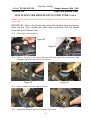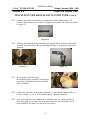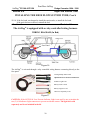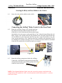
1
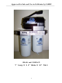
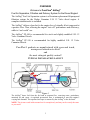
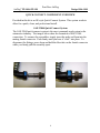
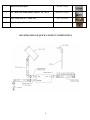
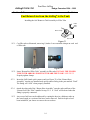
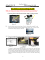
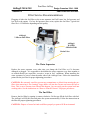
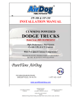
#2
MODEL FP-100 & FP-150
INSTALLATION MANUAL
CUMMINS POWERED
DODGE TRUCKS
Model Year 1994 THROUGH 1998
High Performance Fuel System!
With New Quick Connect Components!
READ INSTRUCTIONS THOROUGHLY
BEFORE BEGINNING INSTALLATION
PureFlow AirDog
705 MAUSOLEUM ROAD
SHELBYVILLE, IN 46176
1-877-421-3187
www.pureflowairdog.com
CANADIAN PATENT
2,108,391
PROTECTED BY
US PATENTS
5,355,860; 5,746,184; 6,729,310
AUSTRALIAN PATENT
2005101054
NEW ZEALAND PATENT
532356
Additional Foreign Patents Pending in Europe, South America, Mexico, Japan, and China!
Approved for Sale and Use in California by CARB!
SMALL and COMPACT
7” Long X 3.2” Wide X 10” Tall
2
OVERVIEW
Welcome to PureFlow® AirDog®
Fuel Air Separation, Filtration and Delivery System for the Diesel Engine!
The AirDog® Fuel Air Separation system is a Premium replacement lift pump and
filtration system for the Dodge Cummins 5.9L 12 Valve diesel engine. A
complete installation kit is included.
The AirDog® delivers clean fuel to the engine free of virtually all air/vapor and at
a positive flow. Thus, allowing the engine “test cell” performance and efficiency,
while in “real world” use.
The AirDog® FP-100 is recommended for stock and slightly modified 5.9L 12
Valve Cummins Diesels.
The AirDog® FP-150 is recommended for highly modified 5.9L 12 Valve
Cummins Diesels.
PureFlow® products are manufactured with a personal touch,
unsurpassed attention to detail
and
the most stringent quality control!
TYPICAL INSTALLATION LAYOUT
Fuse Panel
Figure 1
The AirDog® draws fuel from the fuel tank at constant flow, removing water, particulates,
entrained air and vapor. A regulated pressurized flow is maintained to meet the engine’s
varying fuel demands. The separated air/vapor is returned by the AirDog® to the fuel tank.
NOTE: The pictures used in this manual are for example only and may not be exactly the same
as your truck.
3
PureFlow AirDog
®
AirDog FP-100 & FP-150
Dodge 1994-1998
QUICK CONNECT COMPONENT OVERVIEW
Provided in this kit is an OE style Quick Connect System. This system works to
allow for a quick, clean, and professional install.
SAE J2044 Quick Connect System
The SAE J2044 quick connect system is the most commonly used system in the
automotive industry. The images below show the formation of SAE J2044
connection. To connect the assemblies, simply insert the male end form into the
mating female connector. Push firmly until you hear it “click” into place. To
disconnect the fittings, press down and hold the blue tabs on the female connector
while you firmly pull the assembly apart.
4
PureFlow AirDog
AirDog® 100 & 150
Dodge Cummins 1994 - 1998
Table of Contents
Section 1
TABLE OF CONTENTS
Section 1………........................................………………..Table of Contents
Section 2…..................................................Installation & Safety Guidelines
Section 3..……….................................................………………….Parts List
INSTALLATION PROCEDURES
Section 4…...…………………..………………AirDog® & Mounting Brackets
FUEL LINES
Section 5 A………….…..………………………………………Fuel To Engine
Section 5 B……….….…….………..Injection Pump & Injector Bleed Return
Section 5 C………………………………….…..AirDog® Fuel Return to Tank
FUEL SUCTION LINES
Section 5 D…………….…...……………..………..Suction Line FP-100 Only
Section 5 E………..…….…………………………..Suction Line FP-150 Only
(Includes Hi Flow Suction Tube)
ELECTRICAL HARNESS
Section 6…..…………………...…………………………….Electrical Harness
Section 7..………….……….…………………….…..Initial Startup Procedure
MAINTENANCE
Section 8…………….…………..…….……Filter Service Recommendations
Section 9……………………………………...Cleaning the Gerotor Assembly
Section 10………….……………………………..…..The Pressure Regulator
5
PureFlow AirDog
AirDog® 100 & 150
Dodge Cummins 1994 - 1998
Installation & Safety Guidelines
Section 2
AirDog®
MODEL FP-100 & FP-150
The installation of your AirDog® can be made relatively easy by following the steps outlined in
this manual, and:
1. Inventory the package components completely. Notify PUREFLOW® AIRDOG
immediately of any parts missing or damaged.
2. Read the installation manual completely. Understand how the system operates and
installation recommendations before beginning installation.
3. The installation recommendations contained herein are suggested
guidelines only. Individual installations may vary.
installation
4. If any installation procedure is uncertain, contact PUREFLOW® AIRDOG for
technical assistance.
5. When installing the AirDog® fuel lines be sure to keep the ORIGINAL ENGINE
RETURN LINE connected as it is from the factory!
SAFETY GUIDELINES!
CAUTION! Please be sure to chock the vehicle’s tires to prevent rolling.
CAUTION! Please use proper supports when working beneath an
elevated vehicle.
CAUTION! Most diesel pickups have two (2) 12volt batteries. Disconnect the battery cables
to both batteries before proceeding with the AirDog® installation.
CAUTION! Vehicle frame rails should not be drilled into or welded upon.
CAUTION! Wear safety glasses when operating power tools such as drills and grinders or
when using a punch or chisel.
CAUTION! Use common sense when routing fuel lines and electrical harnesses. Keep them
away from hot exhaust components and/or moving parts. Properly secure lines
to prevent chaffing.
Use Good Judgment and Common Sense When Installing the AirDog®!
6
PureFlow AirDog
AirDog® 100 & 150
Dodge Cummins 1994 - 1998
Parts List
Section 3
AirDog® Parts List
QTY
DESCRIPTION
Part Number
1
Installation Manual
1
AirDog®
201-1-0102
FP-100
Or
FP-150
1
AirDog® Mounting Bracket
001-3C-0004
Mounting Hardware Kit,
1
901-61-0102-PM
010-3C-0002PC
010-3C-0001PC
1
Frame Bracket Set
1
1
Wiring Harness
Bundle of Plastic Ties
1
Return Fuel Filler Tube (with 2 Clamps)
1
“P” Pump Flexible Return Line
1
High Flow Suction Tube (For FP-150’s Only)
1
Grommet (For FP-150’s Only)
1
Spacer
1
Suction Hose Assembly (For FP-100 Only)
WAP110-8-6
1
Suction Hose Assembly (For FP-150 Only)
WAP110-8-8
1
Return Hose Assembly
WAP107-8-8
1
Pressure Hose Assembly
1
14mm X ½” male SAE J2044 Fitting
5E-2-010
5H-2-1-06/12
001-4A-1-0175
4C-1-02-05-001
WAP108
5J-1-1-04-0001
010-3C-0003-A-P
WAP110-8-8-90
WAP103
1
Sealing Washer (installs on WAP103 fitting)
1
Customer Service Oring Replacement Kit
1P-5-ES
901-05-0101
7
IMAGE
3
Push Lock Hose Splice
001-4A-1-0026
2
1/2” Male SAE J2004 Quick Connect x 3/8” NPTF
2
5/16” Push Lock X ¼” Male NPT
4A-1-18-05-04
1
Injection Pump Return Tee
001-4A-1-0008
08J2044-3/8 NPTF
ILLUSTRATION OF QUICK CONNECT COMPONENTS
8
PureFlow AirDog
AirDog® 100 & 150
Dodge Cummins 1994 - 1998
Parts List
Section 4
Installing the AirDog® & Mounting Brackets on the Truck’s
Frame!
Figure 2
Figure 3
4-1.
Assemble the AirDog® mounting bracket to the frame bracket.
4-2.
Use the spacer block to clear lines and wiring harnesses on the frame.
Adjust the assembly up or down on the frame bracket as necessary for clearance.
4-3.
Install a 1/2” J2004 QC x 3/8” NPTF male
quick connect (08J2044-3/8NPTF) into the
“ENGINE” and “FUEL IN” ports in the
AirDog®.
Figure 4
Figure 5
FUEL IN
ENGINE
Figure 6
WARNING: The NPT fitting threads must be lubricated with oil or anti-seize compound
before installation to prevent galling!
4-4.
Attach the AirDog® to the frame bracket assembly.
Figure 7
9
PureFlow AirDog
®
AirDog FP-100 & FP-150
Dodge 1998.5 - 2004
AirDog & Mounting Brackets
®
Section 4
Installing the AirDog® & Mounting Brackets on the Truck’s
Frame, cont’d!
NOTE: The AirDog® can be mounted on either the inside or the outside of the frame, as
space or personal choice dictates.
Mount
The AirDog®
Outside
The
Frame
OR
Figure 8
Figure 9
Inside
The
Frame
Figure 10
Figure 11
For this installation, the AirDog® is mounted inside the frame!
4-5.
Clamp the frame between the AirDog® bracket assembly and the backing plate using
the bolts, lock washers, and nuts included in the kit.
Figure 12
4-6. Position the AirDog® on the frame as necessary for clearance.
NOTE: Be sure to mount the AirDog® so the ‘FUEL IN’ port is directed toward the rear of the
vehicle.
Figure 13A
Figure 13B
NOTE: Some pickup model frame rails have a bracket that is used to support the frame during
the manufacturing process. If this bracket is on your frame rail and obstructs the proper
positioning of the AirDog® mounting bracket, you may remove part or all of it, as needed. Be
very careful not to damage the frame flange!
10
PureFlow AirDog
AirDog® 100 & 150
Dodge Cummins 1994 - 1998
Fuel to Engine
Section 5-A
Installing the Fuel Supply Line from the AirDog® to the P-7100!
For optimum engine performance, it is recommended to bypass the factory filter canister
when installing the AirDog® fuel system.
5A-1. Remove the 14mm banjo bolt and original factory fuel supply line at the fuel inlet port
of the P-7100 injector pump and from the original fuel filter head outlet port.
P-7100 Fuel Inlet Port
Figure 14
Figure 15
Figure 16
5A-2. Install the WAP 103 fitting with seal washer into the inlet port of the P-7100 vacated by
the original banjo fitting.
Figure 17
5A-3 Insert the female quick connect end (see figure 18) of the “pressure hose
assembly” into the male quick connect fitting previously installed in the port marked
“ENGINE”. You will a “click” when it connects.
Figure 18
5A-4. Connect the other end of the “pressure hose assembly” to
the inlet fitting installed in step 5A-2. It will “click”
when properly connected.
5A-5 Any excess fuel hose can be addressed by routing the hose in a fashion to take up the
extra length, or a section of the hose can be removed. Push lock splices have been
included if you choose to remove the excess hose.
11
PureFlow AirDog
AirDog® 100 & 150
Dodge Cummins 1994 - 1998
Fuel to Engine
Section 5-A
NOTE: It is not necessary or recommended to keep the factory filter canister in the system, the
additional flow restriction of the factory filter could cause excessive pressure drops.
Section 5-B: P-7100 Injector Pump and Injector Bleed Line Return
NOTE: Fuel is returned from the P-7100 fuel pump and also from the injector bleed line(s).
The original 12 Valve Cummins configuration returns the fuel from the P-7100 injector pump
(Ref. Fig 18) directly to the fuel tank (Ref. Fig. 29) while the injector bleed line is routed to the
inlet port of the fuel filter head (Ref. Fig. 20) to be recycled back to the engine. When installing
the AirDog®, it is best to route the fuel from the injector bleed line back to the fuel tank as
well.
Figure 19
Return line from the
‘P’ Pump.
Figure 20
End of steel line from P-7100
that connects to the tank return line.
Figure 21
Injector Bleed Line
5B-1. Disconnect the injector bleed line (Ref. Fig. 21) by removing the 8 mm banjo bolt. Be
careful to not misplace the O’ring washer that seals the banjo fitting.
5B-2. Disconnect and remove the banjo fitting
and metal fuel line connecting the fuel pump to
filter head the.
5B-3. Remove the fuel filter head.
Figure 22
5B-4. Connect the injector bleed line banjo fitting (Ref. Fig. 22) with 8mm banjo bolt to
the Return “T” Push Lock Coupler.
Figure 23
Figure 25
Figure 24
12
PureFlow AirDog
AirDog® 100 & 150
Dodge Cummins 1994 - 1998
Engine Fuel Return to Tank
Section 5-B
P-7100 Injector Pump and Injector Bleed Return Line, cont’d!
5B-5. Connect the ‘P’ pump metal return line (Ref. Fig. 26) to the return “T” push lock
coupler fitting with the flex fuel line (Ref. Fig. 25).
Figure 26
Figure 27
NOTE: Be sure to plug or cover the port in the fuel pump vacated by the fuel line to prevent
contamination of the pump.
5B-6. Connect the original fuel return line to
the other end of the Return “T” Push
Lock Coupler fitting.
Figure 28
NOTE: The mechanical fuel pump must be disabled by removing the plunger.
5B-7. Remove the mechanical lift pump by removing the two bolts on each side of the
pump. Remove the plunger. Be very careful, DO NOT drop the plunger into the oil
pan.
Block Off Plate
Figure 29
Figure 30
5B-8. Either re-install the pump on the engine without the plunger or cover the mechanical
pump port on the engine with a Big Block Chevy pump “block off” plate from your
local auto parts store.
13
PureFlow AirDog
AirDog® 100 & 150
Dodge Cummins 1994 - 1998
Section 5-C
Fuel Lines
Fuel Return Line from the AirDog® to the Tank
Installing the fuel 'Return to Tank' assembly in Filler Tube
Filler
Tube
Fuel
Return
Fitting
Hose Clamp
Fuel Tank
Figure 31
5C-1. Cut filler tube as illustrated, removing ½ inches. Loose assemble clamps on each end
of filler tube.
Figure 32
Figure 33
5C-2. Insert “Return Fuel Filler Tube” assembly in filler tube. INSTALL THE FILLER
TUBE WITH ARROWS POINTING TOWARD THE TANK!! SEE FIG 32
Properly tighten clamps.
5C-3.
Insert the SAE female quick connect end (see Figure 33) of the “Return Hose
Assembly” into the pre-installed male quick connect fitting in the port marked “Tank”.
The fitting will “click” when properly installed.
5C-4
Attach the other end of the “Return Hose Assembly” onto the male end form of the
“Return Fuel Filler Tube” installed in step 5C-2. A ”click” will be heard when the
fitting is properly connected.
5C-5 Any excess fuel hose can be addressed by routing the hose in a fashion to take up
the extra length, or a section of the hose can be removed. Push lock splices have
been included if you choose to remove the excess hose.
14
PureFlow AirDog
AirDog® 100 & 150
Dodge Cummins 1994 - 1998
Fuel Suction Line
Section 5-D
Fuel Suction Line for AirDog® FP-100!
NOTE: The AirDog® FP-150 requires a High Flow Suction Tube. If you are installing an
AirDog® FP-150 skip Section 5D and go to section 5E for these installation instructions!
Connecting the Fuel Suction Line from the Tank to AirDog® FP-100
Figure 34
5D-1.
Figure 35
Insert the female connect end (see figure 36) of the “Suction Hose Assembly” to the
male quick connect fitting previously installed in the “Fuel In” port. A “click” will be
heard when the fitting is properly connected.
Figure 36
5D-2. Remove the original fuel suction line Quick Connect fitting from fuel tank by squeezing
the tabs on the end of the connector together. Consult factory manual if unsure.
Suction Tube
Quick Connect Fitting
Fuel Return Tube
View From Beneath Bed
Figure 37
Figure 38
Figure 39
In More Detail
To release the quick-connect fitting from the fuel tank suction tube, push the fitting
toward the suction tube while firmly holding the plastic retainer ring into the fitting.
With the plastic ring firmly depressed, pull the fitting assembly from the suction tube.
Use care to hold the retainer ring square to the Quick Connect Fitting body. It may be
difficult to disconnect the fitting if the retainer is cocked or becomes cocked during
removal.
15
PureFlow AirDog
®
AirDog FP-100 & FP-150
Dodge Cummins 1994 - 1998
Fuel Lines
Section 5-D
Fuel Suction Line for AirDog® FP-100, cont’d
5D-2 Very Important: After removing the factory line check to make sure that
the blue plastic retainer was removed with the line. If the blue retainer remained
attached to the tank tube, it MUST be removed before the new fuel line Quick
Connect will connect and seat to the tank suction tube.
5D-3. Attach the other end of the “Suction Hose Assembly” to the male quick connect on the
top of the fuel module where the factory suction line was once located. A “click will be
heard when the assembly is properly connected.
Figure 40
5D-4. Any excess fuel hose can be addressed by routing the hose in a fashion to take up
the extra length, or a section of the hose can be removed. Push lock splices have
been included if you choose to remove the excess hose.
16
PureFlow AirDog
®
AirDog FP-100 & FP-150
Dodge Cummins 1994 - 1998
High Flow Suction Tube
Section 5-E
INSTALLING THE AIRDOG® FP-150 ONLY
HIGH FLOW SUCTION TUBE
The AirDog® 150 includes a ½” High Flow suction tube to accommodate the high flows of this
system. To install the ½ suction tube it is necessary to either drop the fuel tank or to lift the
truck bed.
NOTE: Should you choose to drop the fuel tank, support the tank as it is when it is installed on
the truck. If you let it rest flat on the floor, the tank may squash out and the suction tube will be
too short after the tank is re-installed in the truck. The suction tube, being cut too short may
suck air as the fuel drops below ¼ tank level.
NOTE: Should you choose to pull the pickup bed to access the tank. Be sure to disconnect the
tail light wires, fuel tank filler tube, and any other accessories or components that may be
secured to the frame and bed.
When Dropping the Tank, Always Remember Safety First!
Figure 41
Figure 42
Figure 43
If you choose to remove the bed, properly support the truck bed to prevent
serious injury or death!
Figure 44
Figure 45
17
PureFlow AirDog
®
AirDog FP-100 & FP-150
Dodge Cummins 1994 - 1998
High Flow Suction Tube
Section 5-E
INSTALLING THE HIGH FLOW SUCTION TUBE, Cont’d
NOTE: The fuel tank used for the pictures is an example only and may not be exactly the same
as your tank.
IMPORTANT: Select a location for the suction tube that has adequate clearance
below the bed. Also consider that under hard acceleration, fuel will migrate
toward the back of the fuel tank.
5E-1. Remove the collection basket.
Figure 46
Figure 47
5E-2. Drill a 1-1/8” hole at the selected location in the fuel tank for the suction tube. Hold
a container below the drill point to catch debris.
Figure 48
Figure 49
5E-3. Remove all burrs from the edge of the hole.
Figure 50
Figure 51
5E-4. Install the grommet in the new suction tube access hole.
18
PureFlow AirDog
®
AirDog FP-100 & FP-150
Dodge Cummins 1994 - 1998
High Flow Suction Tube
Section 5-E
INSTALLING THE HIGH FLOW SUCTION TUBE, Cont’d
5E-5. Measure and cut the suction tube to a length that will allow approximately 1/8”
clearance off the bottom of the tank. It is suggested to form the end of the tube similar
to Figure 52.
Figure 52
5E-6. Lubricate the bulkhead fitting with motor oil. Pressing firmly, insert the suction tube
assembly into the grommet. Be sure the bulkhead fitting is completely seated in the
grommet.
Figure 53
Figure 54
5E-7. Re-install the Collection basket.
Re-install the factory return line to the proper
port of the Collection basket before the tank
fully re-installed.
Figure 55
5E-8. Connect the end of the “Suction Hose Assembly” to the bulk head fitting while it is
easily accessible. A “click” will be heard when it is properly installed.
5E-9
Any excess fuel hose can be addressed by routing the hose in a fashion to take up
the extra length, or a section of the hose can be removed. Push lock splices have
been included if you choose to remove the excess hose
19
PureFlow AirDog
®
AirDog FP-100 & FP-150
Dodge Cummins 1994 - 1998
High Flow Suction Tube
Section 5-E
INSTALLING THE HIGH FLOW SUCTION TUBE, Cont’d
5E-10. If the fuel tank was dropped to install the suction tube, re-install the fuel tank.
If the truck bed was removed, reinstall the bed.
Section 6
Electrical Harness
The AirDog® is equipped with a relay controlled wiring harness.
WIRING DIAGRAM (In Red)
Fuse Panel
Figure 56
The AirDog® is activated through a relay controlled wiring harness connecting directly to the
fuse panel.
AirDog® Pump Motor Lead
Optional Pressure Sensor/Switch Lead*
Indicator Light Lead
Battery Positive Lead
Battery Negative Lead
Mini Fuse Tap Relay Lead
Figure 57
CAUTION: If the OPTIONAL Low Pressure Indicator Light is not used, be sure to insulate the
two (2) #10 Indicator Light connectors to prevent accidental contact. The light kit is sold
separately and is not included in the kit.
20
PureFlow AirDog
®
AirDog FP-100 & FP-150
Dodge Cummins 1994 - 1998
Electrical Harness Cont’d
Section 6
Securing the Relay and Fuse Holder to the Vehicle
6-1.
Secure the relay and fuse holder to the vehicle.
Figure 58
Figure 59
®
Connecting the AirDog Relay Control to the Fuse Panel
6-2.
Route the red, Relay Trigger, wire with the mini fuse
tap attached to the fuse panel located inside the cab
on the driver’s side. Insert the mini fuse tap into a spare
fuse holder or key hot source on the panel that is “hot” when the starter Route the red,
Relay Trigger, wire with the mini fuse tap attached to the fuse panel located inside the
cab on the driver’s side. Insert the mini fuse tap into a spare fuse holder or key hot
source on the panel that is “hot” when the starter key is turned to the on position. If you
are installing in a spot that is already in use you will need to remove that fuse and install
it into the fuse tap provided so both fuse spots are occupied.
Figure 60
6-3.
Route the AirDog® pump motor lead to the AirDog®.
Connect the 2 pin Deutsch connector on the end of the
wiring harness into the corresponding pump motor lead
connector on the AirDog®.
NOTE: If the Optional Indicator Light is not used, secure the pressure switch lead to the
wiring harness with a plastic tie. Also, cover the pressure sensor lead to protect it you may
want to use it later.
21
NOTE: The power supply leads can be connected to the battery or the alternator. Connecting
the power supply leads to the alternator instead of the battery will create a corrosion free
connection.
Black (-)
Red (+)
Replace the Protective Cover
Figure 62
Figure 63
6-4A. Route the Red & Black power supply leads to the alternator Connect the Black (-)lead
to the alternator Chassis Ground connection. Connect the Red (+) lead to the alternator
Hot Lead going to the battery.
6-4B. Should you choose to connect the power supply leads directly to the battery,
connect the RED (+) lead to the POSITIVE (+) post of the driver's side battery.
Connect the BLACK (-) lead to the NEGATIVE (-) post of the same battery.
Black (-)
Red (+)
Figure 64
22
PureFlow AirDog
AirDog® 100 & 150
Dodge Cummins 1994 - 1998
Initial Startup Procedures
Section 7
INITIAL START PROCEDURE
The AirDog® is a self priming system, however, to prevent potential damage to the system, it is
recommended to fill only the pre-filter with diesel fuel before initial startup.
7-1.
Fill the water separator with diesel fuel.
7-2.
Turn the starter key to the on/run position.
7-3.
While the AirDog® is operating, bleed the fuel line to the engine of air by loosening the
fuel line connection at the engine fitting. As soon as the line is purged of air and pure
fuel is observed, properly tighten the fuel fitting. NOTE: put a rag or shop towel over
and around fitting to prevent splatter. Catch all spilled fuel and dispose of properly.
7-4.
Start engine!
RECHECK ALL FUEL FITTINGS FOR LEAKAGE AND PROPERLY TORQUE. BE
SURE ALL FUEL LINES ARE PROPERLY ROUTED TO PROTECT FROM
EXCESSIVE HEAT AND SECURED TO PROTECT FROM CHAFFING AND
ABRASION. RECHECK ALL ELECTRICAL LINES, SECURE AS NECESSARY.
Checking Pump Noise!
NOTE: Each AirDog® has been manufactured in a Quality Controlled process and wet tested
for operation and performance before shipment. This is a very quiet and smooth running
system. However, if any fuel fitting on the vacuum side, between the fuel tank and the AirDog ®
or the pre-filter, has been left loose during the installation process, the system may suck air at
an excessive rate and will be very noisy. To check for this problem, unscrew the pre-filter 3 or
4 full turns and activate the AirDog® by turning the ignition switch to on. If the AirDog® runs
quietly, then excessive air from a loose fitting or leaking pre-filter seal is most likely the reason
for the excessive noise. Correct as necessary.
A.
The seal groove in the 3” water separator is a snug fit and on occasion the seal has been
found to not be fully seated. Remove the water separator; remove the seal from the top
of the nut plate. Clean and lubricate the seal groove. Carefully replace the seal in the
groove. Be sure to fully seat the seal.
B.
Check all fittings, especially the quick connect at the tank.
23
PureFlow AirDog
AirDog® 100 & 150
Dodge Cummins 1994 - 1998
Fuel Filter & Pre-filter
Section 8
Filter Service Recommendations
Plugging of either the fuel filter or the water separator itself will cause low fuel pressure and
low flow to the engine. If a low fuel pressure issue exists, replace the fuel filter. Typical fuel
filter life is 15-20k miles depending on fuel quality.
AirDog®
2 Micron Fuel Filter
AirDog®
WATER
SEPARATOR
Drain Valve
The Water Separator
Replace the water separator every other time you change the Fuel Filter or if it becomes
damaged or plugged. It is suggested to check/drain the water separator every three months or
as needed should you experience excessive ‘water in fuel’ conditions. When installing the
water separator, be sure to clean the under side of the AirDog® base. Follow the instructions
printed on the pre-filter for proper tightening procedures.
CAUTION: Be extremely careful to prevent any contaminates or debris from entering the prefilter when removing it for cleaning! Large debris will jam the Gerotor and cause the fuse to
blow. This is not a warranty item. Should this happen, you can easily put the system back into
working order. See the instructions on “How to clean the Gerotor” for proper procedures.
The Fuel Filter
Remove the fuel filter by turning it counter clockwise. Do Not pre-fill the fuel filter with fuel.
The AirDog® will fill the filter and prime the system automatically. Follow the instructions on
the filter for proper tightening procedures.
CAUTION: Dispose of waste fuel and used filters properly to protect OUR environment!
24
PureFlow AirDog
AirDog® 100 & 150
Dodge Cummins 1994 - 1998
AirDog® Fuel Pump
Section 9
Cleaning Foreign Debris from the Gerotor Assembly
Step 1
Remove the four (4) socket
head cap crews that secure
the gerotor cap.
Step 4
Clean the inside of the
gerotor pocket.
Step 2
Step 3
Carefully remove the O’ring, Remove and clean the gerotor.
you will need to re-use it.
Be very careful not to damage
the gerotor.
Step 5
Replace the O’ring and
center gear.
Step 6
Align the teeth and
install the outer gear.
Step 7
Install the gerotor cap. Be very
careful to index the cap to position
the wide space between the half
moon cuts to the bottom.
Step 8
Replace the cap into
position. Be very careful,
do not pinch the O’ring.
Torque the cap screws.
in an opposing pattern.
1
4
3
25
2
PureFlow AirDog
AirDog® 100 & 150
Dodge Cummins 1994 - 1998
Pressure Regulator Upgrade
Section 10
Changing the Regulator Spring
The AirDog® is shipped from the factory with the fuel pressure preset.
For the 1994-1998 Dodge Cummins, the AirDog® fuel outlet pressure is preset at 25/30 PSI.
Should the need arise to change the spring follow the instructions outlined below.
Regulator Spring Replacement Procedure
The regulator spring and ball assembly is located inside the Return to Tank
fuel port.
Step 1. Disconnect the ‘Return to Tank’ fuel line.
Figure 10-1
Figure 10-2
Figure 10-3
Step 2. Remove the ‘Return to Tank’ fuel line fitting exposing the regulator spring.
Step 3. Remove the ball and spring.
Figure 10-4
Figure 10-5
Figure 10-6
Step 4. Install the new regulator spring by reversing the steps shown in Figures 10-1 through
10-6. Be sure to place the regulator ball in the regulator seat before inserting the spring.
Properly torque the return line fitting and snap the connection when finishing.
26
PUREFLOW AIRDOG
LIFETIME LIMITED EXPRESS WARRANTY
FOR
Covered PureFlow AirDog I, II and Raptor Systems
IMPORTANT NOTICE
TO ACTIVATE YOUR PURFLOW AIRDOG WARRANTY, YOU MUST COMPLETE AND
MAIL YOUR WARRANTY CARD TO PUREFLOW AIRDOG WITH A COPY OF YOUR
ORIGINAL SALES RECEIPT WITHIN 30 DAYS OF PURCHASE. FAILURE TO
COMPLETE AND SUBMIT YOUR WARRANTY CARD WILL RESULT IN A WARRANTY
PERIOD OF THE COVERED PRODUCE TO ONE (1) YEAR FROM THE DATE OF
PURCHASE.
PureFlow AirDog (hereafter collectively, “SELLER”) warrants and guarantees only to the Original Purchaser
(hereafter collectively, BUYER) that the PureFlow AirDog systems FP-100, FP-150, Raptor Fuel Pump RP-100 or
RP-150 (hereafter collectively, PRODUCT) shall be free from defects of materials and workmanship in the
manufacturing process for as long as the BUYER owns the PRODUCT.
The Lifetime Limited Express Warranty is limited to the PRODUCT purchased by the original BUYER of the
PRODUCT and limited solely to the parts contained within the PRODUCT and EXCLUDES ALL ELSE
INCLUDING FILTERS AND WATER SEPARATORS. Any PRODUCT that is in question of Warranty must be
returned, shipped prepaid, to PureFlow AirDog. All Warranty claims are subject to the approval of PureFlow
AirDog. If it is determined that a Warranty claim exists, PureFlow AirDog will, at its sole discretion, replace the
defective PRODUCT with a comparable PRODUCT, repair the defective PRODUCT, or refund the BUYER”S
purchase price in exchange for the PRODUCT. Repairs or replacements are warranted for only the remainder of
the original warranty period and only to the original BUYER.
Under no circumstances shall the SELLER be liable for any labor charged or travel time incurred in the diagnosis
for defects, removal, or reinstallation of the PRODUCT, or any contingent expense.
Under no circumstances will the SELLER be liable for any damage or expense incurred by reason of the use or
sale of the PRODUCT.
Other than expressly set forth herein, the SELLER shall in no way be responsible for the proper or improper use
and service of the PRODUCT. In no event shall the SELLER be liable for any special, incidental, indirect or
consequential damages of any kind or nature, whether or not the BUYER of the PRODUCT was advised of the
possibility of damage or harm, arising or resulting from the use or performance of the PRODUCT and BUYER
hereby waives the right to any and all such claims.
BUYER, acknowledges that he/she is not relying on SELLER’S skill or judgment to select or furnish goods
suitable for any particular purpose and that SELLER has no liability that will extend beyond the scope of the
LIMITED EXPRESS WARRANTY contained herein, and BUYER hereby waives all remedies or liabilities,
expressed or implied, arising by operation of law or otherwise.(including, without limitation, any obligation of
SELLER with respect to fitness for any particular purpose; merchantability; and special, incidental, indirect or
consequential damages) or whether or not occasioned by SELLER’S negligence.
SELLER disclaims any warranty and expressly disclaims any liability for personal inquiry or damages related to
BUYER’S use of the PRODUCT. BUYER acknowledges and agrees that the disclaimer of any liability for
personal injury is a material term for this agreement and BUYER agrees to indemnify SELLER and hold SELLER
harmless from any claim related to the PRODUCT and its use or performance. Under no circumstances will
SELLER be liable for any damages, liabilities, costs or expenses incurred as a result of or by reason of use,
performance or sale of the PRODUCT, including without limitation, any damages, liabilities, costs or expenses
incurred by reason of BUYER’S negligence related to those uses of the PRODUCT.
The proper installation of the PRODUCT is the sole responsibility of the BUYER. The SELLER assumes no
liability regarding improper installation or misapplication of the PRODUCT.
27
SELLER hereby provides the following limited warranty as to description, quality, merchantability, fitness for the
PRODUCT’S purpose, productiveness, or any other matter of SELLER’S PRODUCT sold herewith. The
SELLER shall be in no way responsible for the open use and service of the PRODUCT and the BUYER hereby
waives all rights other than those expressly written herein. This Warranty shall not be extended or varied except
by a written instrument signed by SELLER and BUYER.
IN THE EVENT THAT THE BUYER DOES NOT AGREE WITH THIS AGREEMENT, THE BUYER
MAY PROMPTLY RETURN THE PRODUCT, IN A NEW AND UNUSED CONDITION, WITH A
DATED PROOF OF PURCHASE, TO THE PLACE OF PURCHASE WITHIN THIRTY (30) DAYS
FROM THE DATE OF PURCHASE FOR A FULL REFUND. THE BUYER AGREES THAT THE
INSTALLATION OF THIS PRODUCT CONFIRMS THE BUYER HAS READ AND UNDERSTANDS
THIS AGREEMENT AND ACCEPTS THE TERMS AND CONDITIONS OF THIS AGREEMENT.
Warranty Procedure
In the unlikely event a warranty appears as if it may be warranted, the following steps are taken:
1 The customer discussed the symptoms of the problem with a PureFlow AirDog Technician. The
customer is to have the system Serial Number and Model Number available for the Technician
when the call is made. This will expedite all steps of the process.
2 The customer performs any and all tests requested by the PureFlow AirDog Technician. This is done to
isolate the potential problem while eliminating potential installation or maintenance related issues,
3 If the PureFlow AirDog Technician determines based on the customer feedback concerning the
requested testing that system may be at fault, the customer is advised that all returned pumps are
tested upon arrival and should this returned pump perform at design criteria upon arrival, the
customer will be charged a $50.00 fee.
4 The PureFlow AirDog Technician will first request the customer’s phone number in the event the phone
call is accidentally disconnected and then transfer the customer to a PureFlow AirDog Customer
Service Representative. Should a Customer Service Representative not be available, the Technician
will offer the Customer the option to hold, call back, or receive a return call.
5 The PureFlow AirDog Customer Service Representative will check to determine if the customer’s
Warranty Registration Card is on file.
a. If no Warranty Registration is found, the customer will be required to supply the original
purchase receipt showing the purchase date.
b. If no Warranty Registration is found, the customer will be advised of the options should the
system in question is out of the default warranty period (1 year).
6 The PureFlow AirDog Customer Service Representative will request the customer information, including:
Name, Address, Phone Number, Model Number, Serial Number, Year / Make / Model of vehicle,
Name of Dealer purchased from, Purchase Date, Description of Problem, Customers’ understanding
of the resolution, and customer credit card information.
7 PureFlow AirDog will cover Ground Shipping charges to ship the replacement unit and will include a
prepaid shipping label for the return of the defective unit. Any additional items ordered at the time
of the replacement shipment will include their portion of the shipping cost.
8 A period of 15 Calendar Days from the time of shipment is provided for the receipt of the defective unit
at the PureFlow AirDog facility. Failure to return ship the defective unit to arrive within the defined
time period will result in a charge of $250.00 against the customer’s credit card as the purchase
cost of the defective unit.
PFT Bulletin No. 201-1-0102
Revised July 24, 2014
28