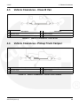
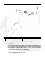
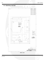
1
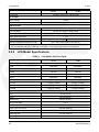
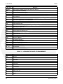
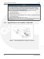
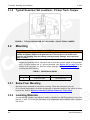
Installation Manual
RV Generator Set
KY (Spec P)
English
Original Instructions
2-2015
A041D129 (Issue 4)
Table of Contents
1. IMPORTANT SAFETY INSTRUCTIONS .......................................................................................
1.1 Overview .................................................................................................................................
1.2 Warning, Caution, and Note Styles Used in This Manual ......................................................
1.3 General Safety Precautions....................................................................................................
1.4 Automatic Generator Start Control Hazards ...........................................................................
1.5 Electrical Shock and Arc Flash Can Cause Severe Personal Injury or Death .......................
1.6 Generator Voltage Is Deadly ..................................................................................................
1.7 Engine Exhaust/Carbon Monoxide Is Deadly .........................................................................
1.8 Fuel Is Flammable and Explosive...........................................................................................
1.9 Battery Gas Is Explosive.........................................................................................................
1.10 Moving Parts Can Cause Severe Personal Injury or Death .................................................
1.11 CARB ....................................................................................................................................
1
1
1
1
3
3
3
4
5
5
5
6
2. INTRODUCTION............................................................................................................................
2.1 About This Manual..................................................................................................................
2.2 Related Literature ...................................................................................................................
2.3 Installation Codes and Standards for Safety ..........................................................................
2.4 Electromagnetic Compatibility Compliance.............................................................................
2.5 Specifications..........................................................................................................................
2.5.1 Gasoline Model Specifications.....................................................................................
2.5.2 LPG Model Specifications..........................................................................................
2.6 List of Acronyms ...................................................................................................................
7
7
7
8
9
9
9
10
11
3. LOCATION, MOUNTING, AND VENTILATION ...........................................................................
3.1 Location ................................................................................................................................
3.1.1 Typical Generator Set Locations - Class A RV..........................................................
3.1.2 Typical Generator Set Locations - Class C RV .........................................................
3.1.3 Typical Generator Set Locations - Class B Van ........................................................
3.1.4 Typical Generator Set Locations - Pickup Truck Camper .........................................
3.2 Mounting ...............................................................................................................................
3.2.1 Below Floor Mounting ................................................................................................
3.2.2 Insulating Materials ....................................................................................................
3.2.3 Fire and Exhaust Barriers ..........................................................................................
3.3 Ventilation .............................................................................................................................
15
15
16
17
17
18
18
18
18
19
19
4. EXHAUST CONNECTIONS.........................................................................................................
4.1 Tailpipe Installation ...............................................................................................................
4.2 Vehicle Clearances - Class A RV .........................................................................................
4.3 Vehicle Clearances - Class B Van........................................................................................
4.4 Vehicle Clearances - Pickup Truck Camper.........................................................................
21
21
24
25
25
5. FUEL CONNECTIONS.................................................................................................................
5.1 Gasoline Motorized ...............................................................................................................
27
27
A041D129 (Issue 4)
i
Table of Contents
2-2015
5.1.1 Fuel Hoses.................................................................................................................
5.1.2 Fuel Lines...................................................................................................................
5.1.3 Routing Fuel Lines .....................................................................................................
5.2 Gasoline Nonmotorized (EVAP) ...........................................................................................
5.2.1 Fuel Hoses.................................................................................................................
5.2.2 Fuel Lines...................................................................................................................
5.2.3 Routing Fuel Lines .....................................................................................................
5.2.4 Vapor and Fuel Return Line Requirements ...............................................................
5.2.5 Fuel Tank ...................................................................................................................
5.2.6 Carbon Canister .........................................................................................................
5.2.7 Generator Set.............................................................................................................
5.3 LPG.......................................................................................................................................
28
29
29
30
33
33
34
34
34
35
36
36
6. ELECTRICAL CONNECTIONS....................................................................................................
6.1 AC Power Output Connections.............................................................................................
6.1.1 Wiring Methods ..........................................................................................................
6.1.2 Connecting to Shore Power .......................................................................................
6.2 Remote Control Connections................................................................................................
6.3 Starting Battery Connections ................................................................................................
6.3.1 Battery Compartment .................................................................................................
6.3.2 Battery Cable Sizes ...................................................................................................
6.3.3 Battery Cables............................................................................................................
6.3.4 Battery Cable Connections at the Generator Set ......................................................
6.3.5 Generator Set (Equipment) Grounding Screw ...........................................................
41
41
42
42
43
44
45
45
45
47
48
7. INSTALLATION REVIEW AND STARTUP ..................................................................................
7.1 Installation Review ................................................................................................................
7.2 Startup ..................................................................................................................................
7.3 Hot Air Recirculation Test .....................................................................................................
7.3.1 Test Method ...............................................................................................................
7.3.2 Test Requirement.......................................................................................................
49
49
49
50
50
51
APPENDIX A. WIRING DIAGRAMS .................................................................................................
A.0 Wiring Diagram.....................................................................................................................
53
55
APPENDIX B. OUTLINE DRAWINGS ..............................................................................................
B.0 Outline Drawing ....................................................................................................................
B.1 Outline Drawing - EVAP .......................................................................................................
B.2 Outline Drawing - Floor Cutout.............................................................................................
57
59
60
61
ii
A041D129 (Issue 4)
1
Important Safety Instructions
1.1
Overview
Thoroughly read the Operator Manual before operating the generator set. It contains important
instructions that should be followed during operation and maintenance. Safe operation and top
performance can only be achieved when equipment is properly operated and maintained. The
owners and operators of the generator set are solely responsible for its safe operation.
Generator set operation, maintenance, and installation must comply with all applicable local,
state, and federal codes and regulations. Electricity, fuel, exhaust, moving parts, and batteries
present hazards which can result in severe personal injury or death. Only trained and
experienced personnel with knowledge of fuels, electricity, and machinery hazards should
perform generator set installation or adjustment procedures; or remove, dismantle, or dispose of
the generator set.
1.2
Warning, Caution, and Note Styles Used in This
Manual
The following safety styles and symbols found throughout this manual indicate potentially
hazardous conditions to the operator, service personnel, or equipment.
DANGER
Indicates a hazardous situation that, if not avoided, will result in death or serious injury.
WARNING
Indicates a hazardous situation that, if not avoided, could result in death or serious
injury.
CAUTION
Indicates a hazardous situation that, if not avoided, could result in minor or moderate injury.
NOTICE
Indicates information considered important, but not hazard-related (e.g., messages relating to
property damage).
1.3
General Safety Precautions
WARNING
Operation of equipment is unsafe when mentally or physically fatigued. Do not operate
equipment in this condition, or after consuming any alcohol or drug.
A041D129 (Issue 4)
1
1. Important Safety Instructions
2-2015
WARNING
Maintaining or installing a generator set can cause severe personal injury. Wear personal
protective equipment such as safety glasses, protective gloves, hard hats, steel-toed boots, and
protective clothing when working on equipment.
WARNING
Running the generator set without the cover or service door can cause severe personal injury or
equipment damage. Do not operate the generator set with the cover or service doors removed.
WARNING
Starting fluids, such as ether, can cause explosion and generator set engine damage. Do not use.
WARNING
Benzene, found in some fuels, has been identified by some state and federal agencies to cause
cancer or reproductive toxicity. Do not ingest, breathe the fumes, or contact gasoline when
checking, draining, or adding gasoline.
WARNING
Used engine oils have been identified by some state and federal agencies to cause cancer or
reproductive toxicity. Do not ingest, breathe the fumes, or contact used oil when checking or
changing engine oil.
CAUTION
To prevent accidental or remote starting while working on the generator set, disconnect the
negative (-) battery cable at the battery using an insulated wrench.
CAUTION
Unsecured or loose fasteners can cause equipment damage. Make sure all fasteners are secure
and properly torqued.
CAUTION
Oily rags and other material can cause fire and restrict cooling. Keep the generator set, drip pan,
and compartment clean.
CAUTION
Accumulated grease and oil can cause overheating and engine damage presenting a potential
fire hazard. Keep the generator set clean and repair any oil leaks promptly.
NOTICE
Keep multi-class ABC fire extinguishers handy. Class A fires involve ordinary combustible
materials such as wood and cloth. Class B fires involve combustible and flammable liquid fuels
and gaseous fuels. Class C fires involve live electrical equipment. (Refer to NFPA No. 10 in
applicable region.)
2
A041D129 (Issue 4)
2-2015
1.4
1. Important Safety Instructions
Automatic Generator Start Control Hazards
WARNING
Accidental starting can cause severe personal injury or death. Turn off the AGS
whenever performing maintenance or service, when the vehicle is stored between uses,
is awaiting service, or is parked in a garage or other confined area.
Unexpected starting may occur if the generator set is equipped with an inverter-charger or other
Automatic Generator Start (AGS) control. This may cause exposure to:
• Unexpected generator starting
• Moving parts hazards
• Electric shock
• Exhaust carbon monoxide (CO)
1.5
Electrical Shock and Arc Flash Can Cause Severe
Personal Injury or Death
WARNING
Electrical shocks and arc flashes can cause severe personal injury or death. Adhere to
the following guidelines:
• Only qualified service personnel certified and authorized to work on power circuits should
work on exposed energized power circuits.
• All relevant service material must be available for any electrical work performed by certified
service personnel.
• Exposure to energized power circuits with potentials of 50 VAC or 75 VDC or higher poses a
significant risk of electrical shock and electrical arc flash.
• Refer to standard NFPA 70E, or equivalent safety standards in corresponding regions, for
details of the dangers involved and for safety requirements.
1.6
Generator Voltage Is Deadly
WARNING
Improperly connected generator electrical output connections can cause equipment
damage, severe personal injury, or death. Electrical connections must be made by a
trained and experienced electrician in accordance with applicable codes.
WARNING
Improper installations can cause equipment damage, severe personal injury, or death.
All installations must be conducted by trained and experienced personnel in
accordance with the installation instructions and all applicable codes.
WARNING
Back feed to shore power can cause electrocution and damage to equipment. The
generator set must not be connected to shore power or to any other source of electrical
power. An approved switching device must be used to prevent interconnections.
A041D129 (Issue 4)
3
1. Important Safety Instructions
2-2015
WARNING
Live electrical equipment can cause electrocution. Use caution when working on live
electrical equipment. Remove jewelry, make sure clothing and shoes are dry, stand on a
dry wooden platform or rubber insulating mat, and use tools with insulated handles.
1.7
Engine Exhaust/Carbon Monoxide Is Deadly
WARNING
Substances in exhaust gases have been identified by some state and federal agencies
to cause cancer or reproductive toxicity. Do not breathe in or come into contact with
exhaust gases.
WARNING
Carbon monoxide is a poisonous gas. Inhalation of this gas can cause severe personal
injury or death. Adhere to the following bullet points to make sure carbon monoxide is
not being inhaled by occupants of the vehicle as well as others working on or around
the generator set.
• Inspect for exhaust leaks, and test and confirm that all carbon monoxide detectors are
working in accordance with the manufacturer's instructions or owner's manual, prior to
every startup, and after every 8 hours of running.
• Never occupy the vehicle while the generator set is running unless the vehicle is equipped
with a working carbon monoxide detector.
• Never operate the generator set when the vehicle is in a confined space, such as a garage,
basement, or building of any kind.
• Make sure the exhaust system is installed in accordance with the generator set installation
manual.
• Never use engine cooling air for heating a working or living space compartment.
Carbon Monoxide (CO) is odorless, colorless, tasteless, and non-irritating. It cannot be seen or
smelled. Exposure, even to low levels of CO for a prolonged period can lead to asphyxiation
(lack of oxygen).
Mild effects of CO poisoning include:
• headache
• dizziness
• drowsiness
• fatigue
• chest pain
• confusion
More extreme symptoms include:
• vomiting
• seizure
• loss of consciousness
4
A041D129 (Issue 4)
2-2015
1.8
1. Important Safety Instructions
Fuel Is Flammable and Explosive
WARNING
Fuel and fuel vapor is highly explosive. Adhere to the following bullets to avoid igniting
fuel and fuel vapors.
• Do not smoke or turn electrical switches on or off where fuel fumes are present or in areas
sharing ventilation with fuel tanks or equipment.
• Keep flame, sparks, pilot lights, arc-producing equipment and all other sources of ignition
well away from fuel lines and sources.
• Fuel lines must be secured, free of leaks, and separated or shielded from electrical wiring.
Leaks can lead to explosive accumulations of gas.
• LPG sinks when released and can accumulate inside housings and basements and other
below-grade spaces.
NOTICE
Natural gas is identifiable by a rotten egg smell.
1.9
Battery Gas Is Explosive
WARNING
Battery gas is highly explosive and may cause personal injury or death if ignited. Take
the proper precautions to avoid personal injury.
• For personal safety, wear appropriate PPE when working on or around the generator set.
• To make sure battery gas is not ignited, do not smoke around the generator set.
• To reduce arcing when disconnecting or reconnecting battery cables, always disconnect
the negative (–) battery cable first and reconnect it last.
1.10
Moving Parts Can Cause Severe Personal Injury or
Death
WARNING
Moving parts can cause severe personal injury or death, and hot exhaust parts can
cause severe burns. Make sure all protective guards are properly in place before
starting the generator set.
WARNING
Hot moving, and electrically live parts can cause severe personal injury or death. Keep
children away from the generator set.
A041D129 (Issue 4)
5
1. Important Safety Instructions
2-2015
WARNING
Hot, moving, and electrically live parts can cause severe personal injury or death. Only
trained and experienced personnel should make adjustments while the generator set is
running.
WARNING
Moving parts can catch on loose items such as clothing or jewelry. Do not wear loose
clothing or jewelry near moving parts such as PTO (power take-off) shafts, fans, belts,
and pulleys.
WARNING
Moving parts can entangle appendages such as fingers. Keep the protective guards in
place over fans, belts, pulleys, and other moving parts and keep hands away from all
moving parts.
1.11
CARB
CAUTION
Unauthorized modifications or replacement of fuel, exhaust, air intake, or speed control
system components that affect engine emissions are prohibited by law in the state of
California.
The California Air Resources Board (CARB) has requirements regarding modification & repair of
fuel system & exhaust components.
6
A041D129 (Issue 4)
2
Introduction
2.1
About This Manual
This manual is a guide for the installation of the generator sets listed on the front cover. Proper
installation is essential for top performance. Read through this manual before starting the
installation. Leave this manual in the vehicle.
The installer must be qualified to perform installation of electrical and mechanical equipment.
This manual addresses the following aspects of the installation:
• Location, Mounting, and Ventilation
• Exhaust Connections
• Fuel Connections
• Electrical Connections
• Startup
See the Operator Manual for operation and maintenance and the Service Manual for service.
The information contained within the manual is based on information available at the time of
printing. In line with Cummins Power Generation policy of continuous development and
improvement, information may change at any time without notice. The users should therefore
make sure that before commencing any work, they have the latest information available. The
latest
version
of
this
manual
is
available
on
QuickServe
Online
(https://qsol.cummins.com/info/index.html).
2.2
Related Literature
Before any attempt is made to operate the generator set, the operator should take time to read
all of the manuals supplied with the generator set, and to familiarize themselves with the
warnings and operating procedures.
CAUTION
A generator set must be operated and maintained properly if you are to expect safe and reliable
operation. The Operator manual includes a maintenance schedule and a troubleshooting guide.
The Health and Safety manual must be read in conjunction with this manual for the safe
operation of the generator set:
• Health and Safety Manual (0908-0110)
The relevant manuals appropriate to your generator set are also available, the documents below
are in English:
• Operator Manual for RV Generator Set KY (Spec P) (A041D131)
• Installation Manual for RV Generator Set KY (Spec P) (A041D129)
• Generator Set Service Manual for RV Generator Set KY (Spec P) (A041D133)
• Recommended Spares List (RSL) for RV Generator Set KY (Spec P) (A043Y023)
A041D129 (Issue 4)
7
2. Introduction
2-2015
• Parts Manual for RV Generator Set KY (Spec P) (0981-0246)
• Standard Repair Times - AF Family (0900-0606)
• Service Tool Manual (A043D529)
• Failure Code Manual (F1115C)
• Warranty Manual (A040W374)
• Global Commercial Warranty Statement (A028U870)
2.3
Installation Codes and Standards for Safety
CAUTION
The Commercial Generator Set Warranty applies only when the generator set is installed in a
commercial or recreational vehicle. The RV Generator Set Warranty applies only when the
generator set is installed in a recreational vehicle.
The installer bears sole responsibility for the selection of the appropriate generator set, for its
proper installation, and for obtaining approvals from the authorities (if any) having jurisdiction
over the installation. The generator sets meet the basic requirements of the Standard for Safety
for Engine Generator Sets for Recreational Vehicles, ANSI/RVIA EGS-1 and are suitable for
installation in accordance with:
• ANSI A1192 (NFPA No. 501C)—Recreational Vehicles
• NFPA No. 70, Article 551—Recreational Vehicles and RV Parks
• CSA Electrical Bulletin 946—Requirements for Internal Combustion Engine-Driven Electric
Generators for Use in Recreational Vehicles
Federal, state, and local codes, such as the California Administrative Code—Title 25 (RV
installation), might also be applicable. Installation codes and recommendations can change from
time-to-time and are different in different countries, states, and municipalities. Obtain the
standards listed in the table below for reference.
TABLE 1.
REFERENCE CODES AND STANDARDS
Code of Federal
Regulations, Title 49:
Chapter III and
Chapter V
Superintendent of Documents
P. O. Box 371954
Pittsburgh, PA 15250-7954
NFPA 58, 70, 1192
National Fire Protection Association
470 Atlantic Avenue
Boston, MA 02210
ANSI/RVIA-EGS-1
Recreational Vehicle Industry Association
14650 Lee Road
Chantily, VA 22021
California
Administrative
Code—Title 25,
Chapter 3
State of California Documents Section
P.O. Box 1015
North Highlands, CA 95660
CAN/CSA-Z240
Recreational Vehicles
Bulletin 946
Canadian Standards Association Housing and Construction Materials Section
178 Rexdale Blvd.
Rexdale, Ontario, Canada M9W 1R3
8
A041D129 (Issue 4)
2-2015
2. Introduction
SAE World Headquarters
400 Commonwealth Drive
Warrendale, PA 15096
SAE J1231, J1508,
J2044, J2599
2.4
Electromagnetic Compatibility Compliance
Generator sets emit and receive electromagnetic (radio frequency) energy. If the generator set
affects operation of nearby devices, or nearby devices affect generator set operation, increase
the distance between them.
When used in countries where compliance to the EMC directive is required: This generator set
has been evaluated for use in the residential, commercial, and light industrial environments.
2.5
Specifications
2.5.1
Gasoline Model Specifications
TABLE 2.
GASOLINE MODEL SPECIFICATIONS
4.0 KY
3.6 KY
GENERATOR: 2-Pole Revolving Field, Self-Excited, 1-Phase, Microprocessor Regulated
Power
4000 Watts
3600 Watts
60 Hz
50 Hz
Voltage
120 Volts
230 Volts
Current
33.3 Amps
15.7 Amps
Speed
3600 RPM
3000 RPM
No Load
1.1 l/h (0.29 gph)
0.79 l/h (0.21 gph)
Half Load
1.8 l/h (0.48 gph)
1.4 l/h (0.37 gph)
Fuel Load
2.7 l/h (0.71 gph)
2.2 l/h (0.58 gph)
1
Frequency
FUEL CONSUMPTION:
ENGINE: 1-Cylinder, 4-Cyle, Spark Ignited, OHV, Air-Cooled, Mechanically Governed
Bore
79 mm (3.11 in)
Stroke
62 mm (2.44 in)
Displacement
Compression Ratio
Oil Capacity
304 cm3 (18.5 in3)
8.5 : 1
1.5 liters (1.6 qt)
Intake Valve Lash (Cold)
0.05 mm (0.002 in)
Exhaust Valve Lash (Cold)
0.05 mm (0.002 in)
Spark Plug Gap
0.64 mm (0.025 in)
Spark Plug Torque
Ignition Timing
Magneto Air Gap
A041D129 (Issue 4)
17 Nm (13 ft-lbs)
25° BTDC, non-adjustable
0.23–0.38 mm (0.009–0.015 in)
9
2. Introduction
2-2015
4.0 KY
3.6 KY
3.9 kgf/cm2 (55.47 lbf/in2) @ 500 RPM
Compression
DC SYSTEM:
Battery Voltage
12 Volts
Minimum Battery Rating
450 CCA @ –18 °C (0 °F)
INSTALLATION:
Exhaust O. D.
28.7 mm (1.13 in)
Fuel Connection
1/4 inch barb fitting for gasoline hose
258 cm2 (40 in2)
Minimum Free Air Inlet Area
Muffler Outlet Collar O.D.
1.13 in
Weight (with engine oil)
81 kg (178 lbs)
2
Minimum Compartment Size (H x D x W)
84 kg (184 lbs)
366 x 508 x 775 mm (14.4 x 20 x 30.5 in)
1. 60 Hz models are listed by CSA and the US Testing Company.
2. See the Installation Manual for additional considerations when sizing the generator set compartment.
2.5.2
LPG Model Specifications
TABLE 3.
LPG MODEL SPECIFICATIONS
3.6 KY
3.3 KY
GENERATOR: 2-Pole Revolving Field, Self-Excited, 1-Phase, Microprocessor Regulated
Power
3600 Watts
3300 Watts
60 Hz
50 Hz
Voltage
120 Volts
230 Volts
Current
30 Amps
14.3 Amps
Speed
3600 RPM
3000 RPM
No Load
0.7 kg/h (1.5 lbs/h)
0.5 kg/h (1.1 lbs/h)
Half Load
1.0 kg/h (2.2 lbs/h)
0.9 kg/h (2.0 lbs/h)
Full Load
1.5 kg/h (3.3 lbs/h)
1.3 kg/h (2.9 lbs/h)
Frequency1
FUEL CONSUMPTION:
ENGINE: 1-Cylinder, 4-Cycle, Spark Ignited, OHV, Air-Cooled, Mechanically Governed
Bore
79 mm (3.11 in)
Stroke
62 mm (2.44 in)
Displacement
Compression Ratio
Oil Capacity
304 cm3 (18.5 in3)
8.5 : 1
1.5 liters (1.6 qt)
Intake Valve Lash (Cold)
0.05 mm (0.002 in)
Exhaust Valve Lash (Cold)
0.05 mm (0.002 in)
Spark Plug Gap
0.51 mm (0.020 in)
Spark Plug Torque
10
17 Nm (13 ft-lbs)
A041D129 (Issue 4)
2-2015
2. Introduction
3.6 KY
Ignition Timing
3.3 KY
25° BTDC, non-adjustable
Magneto Air Gap
0.23–0.38 mm (0.009–0.015 in)
3.9 kgf/cm2 (55.47 lbf/in2) @ 500 RPM
Compression
DC SYSTEM:
Battery Voltage
12 Volts
Minimum Battery Rating
450 CCA @ –18 °C (0 °F)
INSTALLATION:
Exhaust O. D.
28.7 mm (1.13 in)
Fuel Connection
5/8-18 UNC, SAE 45° Flare Fitting
258 cm2 (40 in2)
Minimum Free Air Inlet Area
Muffler Outlet Collar O.D.
1.13 in
LPG Vapor Supply Pressure
228–330 mm (9–13 in) WC
LPG Liquid Connection Pressure
1/4-18 NPTF Tank Pressure
Weight
81 kg (178 lbs)
2
Minimum Compartment Size (H x D x W)
84 kg (184 lbs)
366 x 508 x 775 mm (14.4 x 20 x 30.5 in)
1. 60 Hz models are listed by CSA and the US Testing Company.
2. See the Installation Manual for additional considerations when sizing the generator set compartment.
2.6
List of Acronyms
TABLE 4.
ACRONYM DEFINITIONS
Acronym
Definition
AC
Alternating Current
AGS
Automatic Generator Start
AISI
American Iron and Steel Institute
ANSI
American National Standards Institute
API
American Petroleum Institute
ASTM
American Society for Testing and Materials (now known as ASTM International)
BS
Build Standard
BTDC
Before Top Dead Center
CARB
California Air Resources Board
CCA
Cold Cranking Amp
CFR
Code of Federal Regulations
CO
Carbon Monoxide
CPG
Cummins Power Generation
CSA
Canadian Standards Association
DC
Direct Current
A041D129 (Issue 4)
11
2. Introduction
2-2015
Acronym
Definition
EEPROM
Electronically Erasable Programmable Read Only Memory
EMC
Electromagnetic Compatibility
EPA
Environmental Protection Agency
GFCI
Grounded Fault Circuit Interrupters
hp
High Pressure
I.D.
Inside Diameter
ISO
International Organization for Standardization
LED
Light-emitting Diode
LPG
Liquid Petroleum Gas
NFPA
National Fire Protection Agency
NPTF
National Pipe Taper Fuel
O.D.
Outside Diameter
OEM
Original Equipment Manufacturer
PPE
Personal Protective Equipment
PTO
Power Take-Off
RAM
Random Access Memory
ROM
Read Only Memory
RV
Recreational Vehicle
RVIA
RV Industry Association
SAE
Society of Automotive Engineers
UNC
Unified National Coarse
US, U.S.
United States
WC
Water Column
TABLE 5.
Acronym
Definition
Amp
Ampere
C
Celsius
cm
centimeter
D
Depth
F
Fahrenheit
ft
Feet, foot
ft-lbs
Foot-pounds
g
gram
gph
Gallons per hour
H
Height
Hz
Hertz
12
ACRONYMS FOR UNITS OF MEASUREMENT
A041D129 (Issue 4)
2-2015
2. Introduction
Acronym
Definition
in
Inch
kg
kilogram
kg/h
kilograms per hour
2
kgf/cm
kilogram-force per square centimeter
kW
kilowatt
l/h
Liters per hour
lb
Pound
2
lbf/in OR psi
Pound per square inch
lbs/h
Pounds per hour
m
Meter
mm
millimeter
Nm
Newton meter
2
psi OR lbf/in
Pounds per square inch
qt
Quart
RPM
Revolutions per Minute
VAC
Volts Alternating Current
VDC
Volts Direct Current
W
Watts, Width
A041D129 (Issue 4)
13
2. Introduction
2-2015
This page is intentionally blank.
14
A041D129 (Issue 4)
3
Location, Mounting, and Ventilation
The location, mounting, and ventilation of a generator set must be such that mounting is secure,
engine exhaust and fuel vapors are prevented from entering the vehicle, rain and road debris
are prevented from entering the generator set, and ready access is afforded for operating the
generator set and performing periodic maintenance.
3.1
Location
Typical locations for generator set installation are shown below.
• The location must provide:
• Ready access for starting and stopping the generator set and performing all periodic
maintenance.
• Separation from sources of flammable vapors, such as batteries and fuel tanks, which
the generator set could ignite.
• Access for connecting and disconnecting fuel lines, battery cables, remote control
wiring, and AC wiring.
• Access to single fuel pump screw after removal of control board through service door.
• Access from below for draining engine oil.
• Unobstructed space below the generator set for proper cooling air flow.
• The generator set must not share a compartment or ventilation with batteries or fuel tanks.
An operating generator set can ignite flammable vapors. Make sure that in the first 305 mm
(12 in) of ground clearance there is at least 152.4 mm (6 in) of unobstructed space below
the generator set and open on at least three sides, which is required for proper cooling air
flow.
• Locate or shield the generator set cooling air openings from direct rain, road splash and
debris thrown up by the road wheels.
NOTICE
Mudflaps, air ducts, and deflectors must be used to prevent road debris and tire spray from
going into the generator set.
• The generator set housing is not rain proof. If the generator set is installed where snow
and rain will hit the top of the generator set, a sheet metal or plastic cover should be used
to prevent large amounts of water from running in the seams of the generator set housing.
• Space to mount the generator set with at least 25.4 mm (1 in) clearance on the left side,
25.4 mm (1 in) clearance at the top, 38.1 mm (1.5 in) clearance in front, and 6.35 mm (1/4
in) clearance on the remaining sides of the generator set. Minimum clearances apply to
any thermal or acoustic insulation with which a compartment may be lined.
A041D129 (Issue 4)
15
3. Location, Mounting, and Ventilation
2-2015
NOTICE
For rooftop or other high acceleration locations:
Certain locations for generator set installations can result in 30+ g forces affecting the generator
set. These high road input forces can cause generator set performance issues, from rough
running or stalling to many different types of broken generator set components. It is highly
recommended that the generator set not be located more than 1.524 m (5 ft) above the floor and
aft of the rear axle(s) on a trailer or motorized application.
Damage due to high road input forces (as follows) will not be covered under warranty:
• Broken generator mounts
• Broken exhaust components
• Damaged housings or shrouds from excessive internal generator set component movement
• Torn out wiring harnesses
• Stalling or rough running while the vehicle is in motion
Locating the generator set in these limited access areas also affects proper maintenance. Major
engine damage due to lack of maintenance will not be covered under warranty.
3.1.1
Typical Generator Set Locations - Class A RV
FIGURE 1.
16
TYPICAL GENERATOR SET LOCATIONS - CLASS A RV
A041D129 (Issue 4)
2-2015
3.1.2
3. Location, Mounting, and Ventilation
Typical Generator Set Locations - Class C RV
FIGURE 2.
3.1.3
TYPICAL GENERATOR SET LOCATIONS - CLASS C RV
Typical Generator Set Locations - Class B Van
FIGURE 3.
A041D129 (Issue 4)
TYPICAL GENERATOR SET LOCATIONS - CLASS B VAN
17
3. Location, Mounting, and Ventilation
3.1.4
Typical Generator Set Locations - Pickup Truck Camper
FIGURE 4.
3.2
2-2015
TYPICAL GENERATOR SET LOCATIONS - PICKUP TRUCK CAMPER
Mounting
WARNING
The generator set support structure must be designed and installed to support and
restrain the dynamic weight of the generator set. Failure to do so can result in the
generator set dropping onto the roadway causing property damage, severe personal
injury, or death.
• Support the generator set on a structure able to resist the dynamic weight of the generator
set: ± 3 g-force vertical and ± 1 g-force horizontal. See Section 2.5 on page 9 for the
weight of the generator set. See the outline drawings in Appendix B on page 57 for
mounting bolt hole locations.
TABLE 6.
3.2.1
MOUNTING SCREWS
Quantity
Type
Torque
6
5/16-18 NC bolts
26 Nm (20 ft-lbs)
Below Floor Mounting
Mounting kits are available for below floor mounting. Follow the instructions in the kit.
Do not mount the generator set within the approach or departure angles of the vehicle or below
the axle line. Refer to Exhaust Connections (Vehicle Clearances - Class A RV).
3.2.2
Insulating Materials
Acoustic/thermal insulation and adhesive must be classified as "Self-Extinguishing" at not less
than 90 oC (200 oF). Do not line the bottom of a compartment with insulation since it absorbs
fuel and oil.
18
A041D129 (Issue 4)
2-2015
3.2.3
3. Location, Mounting, and Ventilation
Fire and Exhaust Barriers
WARNING
Exhaust gas and fire are deadly! Install a vapor-tight and fire-resistant barrier of
approved materials between the generator set and the vehicle interior. Do not duct
generator set cooling air into the vehicle for heating.
• Barriers to provide vapor and fire resistance must be installed between the generator set
and the interior of the vehicle if the generator set is mounted below the floor.
• If the generator set is mounted in a compartment on the floor of the vehicle, the entire
compartment must be lined with vapor and fire resistive materials.
• Use approved materials (26 gauge galvanized steel or equivalent). See NFPA 1192 for
details. Refer to local codes and standards for additional information.
• All seams and openings in the barriers for wiring, mounting screws, etc. must be sealed.
3.3
Ventilation
Generator set cooling air must not be obstructed.
• A free-air inlet size of at least 258 cm2 (40 in2) is required. Grilles, louvers, and other kinds
of decorative treatments for air openings are restrictive. Contact the manufacturer of the
decorative assembly or material to find out how large of an opening is required to obtain
the minimum free-air inlet size.
• Unless the compartment air inlet lines up directly with the generator set air inlet, a
clearance of at least 50.8 mm (2 in) is required at the front of the generator set for air to
get to the generator set inlet. Staggering a compartment side opening or pulling the air up
under the skirt of the vehicle will reduce line-of-sight noise but requires the extra clearance
in front.
A041D129 (Issue 4)
19
3. Location, Mounting, and Ventilation
FIGURE 5.
20
2-2015
GENERATOR SET COOLING AIR INLET AND OUTLET
A041D129 (Issue 4)
4
Exhaust Connections
WARNING
This product incorporates a catalyst exhaust system which leads to higher exhaust gas
temperatures. The installer must review and follow all guidelines for the installation. Care must
be taken to make sure that all installation requirements in this entire manual are met.
The generator set is equipped with a U.S. Forest Service approved spark-arrest muffler. Failure
to provide and maintain a spark arrester can be a violation of the law. Liability for damage,
injury, and warranty expense due to the modification of the exhaust system or the use of
unapproved parts is the responsibility of the person performing the modification or installing the
unapproved exhaust system parts.
WARNING
EXHAUST GAS IS DEADLY! To keep exhaust gases from entering the vehicle do not terminate
the exhaust tailpipe underneath the vehicle or closer than 153 mm (6 in) to openings into the
vehicle or route it such that it is not protected. Use approved materials only.
The tailpipe of the generator set will be hot during operation and can cause severe burns. To
reduce the risk of contact, concentration must be used where the tailpipe will be located and
routed.
The generator set exhaust system must be gas tight and designed to prevent entry of exhaust
gasses into the vehicle interior.
4.1
Tailpipe Installation
The muffler is mounted inside the generator set and has a flange to which the tailpipe adapter
(available from Cummins Onan) is bolted or a collar to which the tailpipe is clamped or a short
adapter bolted to its oulet flange.
WARNING
Flexible pipe is not gas tight or durable and can cause exhaust gas leaks. Do not use
flexible pipe for tailpipe.
1. Use 18-gauge 1-3/8 inch I.D. aluminized steel tubing or material of equivalent heat and
corrosion resistance for the tailpipe.
2. Support a tailpipe longer than 457 mm (1-1/2 ft) near its end and at intervals of 900 mm (3
ft) or less. Use automotive-type tailpipe hangers. Do not attach the hangers to combustible
material such as wood.
3. Use U-bolt muffler clamps to connect sections of tailpipe. Overlapping pipe should be
slotted.
4. Do not route the tailpipe within 25.4 mm (1 inch) of fuel lines or fuel tanks.
5. Do not route the tailpipe closer than 76 mm (3 in) to combustible material (wood, felt,
cotton, organic fibers, etc.) unless it is insulated or shielded. The temperature rise (above
ambient) on adjacent combustible material must not exceed 65 °C (117 °F).
6. Do not route the exhaust tailpipe underneath the oil drain.
A041D129 (Issue 4)
21
4. Exhaust Connections
2-2015
7. Do not route the exhaust tailpaipe such that it will restrict the air inlet/outlet.
8. To keep the tailpipe from being damaged, do not route it such that it protrudes into the
approach or departure angles of the vehicle or below the axle clearance line.
9. Do not interconnect generator set and vehicle engine exhaust systems.
10. Do not terminate the tailpipe underneath the vehicle. Extend it a minimum of 25 mm (1 in)
beyond the perimeter of the vehicle. Support the end of the tailpipe such that it cannot be
pushed in and up under the skirt of the vehicle.
11. Do not terminate the tailpipe such that it is closer than 153 mm (6 in) to any opening, such
as a door, window, vent, or unsealed compartment into the vehicle interior.
CAUTION
Excessive back pressure can cause loss of performance and engine damage.
12. Make sure a tailpipe deflector will not cause excessive back pressure.
22
FIGURE 6.
TYPICAL TAILPIPE INSTALLATION
FIGURE 7.
EXHAUST TAILPIPE CONNECTIONS
A041D129 (Issue 4)
2-2015
No.
1
4. Exhaust Connections
Description
Tailpipe
No.
2
Description
153 mm (6 in)
No opening into the vehicle interior may be closer than 153 mm (6 in) to the end of the tail pipe (within area 2,
identified in this image).
FIGURE 8.
A041D129 (Issue 4)
MINIMUM DISTANCES TO OPENINGS
23
4. Exhaust Connections
No.
2-2015
Description
No.
Description
A
Side view
1
25 mm (1 inch)
B
Straight-on view
2
The last tailpipe hanger must be as close to the end
as possible.
FIGURE 9.
4.2
TERMINATING THE EXHAUST TAILPIPE
Vehicle Clearances - Class A RV
No.
Description
1
Approach Angle
2
Axle Clearance Line
No.
3
Description
Departure Angle
FIGURE 10. VEHICLE CLEARANCES - CLASS A RV
24
A041D129 (Issue 4)
2-2015
4.3
4. Exhaust Connections
Vehicle Clearances - Class B Van
No.
Description
1
Approach Angle
2
Axle Clearance Line
No.
3
Description
Departure Angle
FIGURE 11. VEHICLE CLEARANCES - CLASS B VAN
4.4
Vehicle Clearances - Pickup Truck Camper
No.
Description
1
Approach Angle
2
Axle Clearance Line
No.
3
Description
Departure Angle
FIGURE 12. VEHICLE CLEARANCES - PICKUP TRUCK CAMPER
A041D129 (Issue 4)
25
4. Exhaust Connections
2-2015
This page is intentionally blank.
26
A041D129 (Issue 4)
5
Fuel Connections
See the Operator Manual for recommended fuels and Section 2.5 on page 9 for fuel
consumption.
CAUTION
Unauthorized modifications or replacement of fuel, exhaust, air intake, or speed control system
components that affect engine emissions are prohibited by law in California.
5.1
Gasoline Motorized
The maximum fuel pump lift is 914 mm (36 in).
The generator set and propulsion engine fuel supply and return lines must not be
interconnected.
Connections meet the requirements of the following SAE standards, when applicable:
• J1231 (Formed Tube Ends for Hose Connections and Hose Fittings)
• J1508 (Hose Clamp Specifications)
• J2260 (Nonmetallic Fuel System Tubing with One or More Layers)
• J2044 (Quick Connector Specification for Liquid Fuel and Vapor/Emissions Systems)
Terminate the generator set fuel pickup above the vehicle engine pickup in the supply tank to
keep the generator set from running the vehicle out of fuel.
Connect 1/4 inch fuel line from the vehicle fuel tank to the generator set.
A041D129 (Issue 4)
27
5. Fuel Connections
No.
2-2015
Description
1
Fuel Hose
2
Hose Clamp
No.
3
Description
Barb Fitting
FIGURE 13. GASOLINE MOTORIZED FUEL CONNECTION
5.1.1
Fuel Hoses
The fuel hoses used inside the generator set are low permeation fuel hoses which meet Federal
50 state standards for gasoline evaporative emissions. Low permeation fuel hose is required to
meet the requirements for gasoline generator sets sold in or used for commerce in all 50 states.
The following hose materials are acceptable:
• Avon Automotive “Greenbar" (EO# G-05-018) SAE J30R7
• Avon Automotive “Greenbar 1200" (EO# C-U-05-009) SAE J30R12
• Gates 4219D (EO# C-U-06-002) SAE J30R9
• Gates Barricade (EO# Q-09-019)
28
A041D129 (Issue 4)
2-2015
5. Fuel Connections
• Kubota (EO# C-U-05-003) SAE J30R7
• Mark IV Automotive “Gen2" (EO# C-U-05-002) SAE J30R7
• Mark IV Automotive "Fluoroperm" (EO# C-U-07-017) SAE J30R9
• Mark IV Automotive Dayperm" (EO# C-U-06-030) SAE J30R7
• Mark IV Automotive "Dayperm" (EO# G-05-016)
• Mold-Ex Division of SETi, Inc. "SETiFLEX II" (EO# G-05-17A) SAE J30R7
• Parker Hannifin Corp "Super Flex FL-7 series 389XX" (EO# Q-08-013)
• Veyance Technologies Inc. "Goodyear Flexshield" (EO# Q-09-022)
CAUTION
Lubricants used when connecting fuel hoses can leave residues that can clog fuel jets. Only use
soap-free lubricants such as WD40 which runs through with the fuel without leaving residues
that can clog fuel jets.
5.1.2
Fuel Lines
Tubing:
• Use 1/4 inch I.D. (± 0.003 inch) welded and drawn Type 304L stainless or AISI 1008-1010
low carbon steel tubing of 0.028 inch minimum wall thickness.
• Tubing must meet requirements for 150 psi operating pressure (Ref. ASTM A 539-99) and
have corrosion resistance equal to or better than hot-dipped zinc galvanized.
Hose Beads:
• Use suitable tooling to form tubing ends into SAE J1231 Type 1 or Type 3 double-flare
hose beads.
• Recommended for all tubing and fittings.
Flexible Hose: Use 1/4 inch I.D. fuel hose that meets applicable standards for evaporative
emissions.
5.1.3
Routing Fuel Lines
WARNING
Electric arcs can ignite gasoline leading to severe personal injury or death. Do not run
wiring and fuel lines together.
1. Route the fuel line along bulkheads and frame members such that it is protected. The
entire length of the fuel line must be visible for inspection and accessible for replacement.
It is preferred that fuel line routing be parallel to the motorized chassis fuel line.
A041D129 (Issue 4)
29
5. Fuel Connections
2-2015
FIGURE 14. FUEL LINE PREFERRED ROUTING
NOTICE
The fuel line should be at or above the top of the fuel tank to reduce siphoning if a
line breaks or a hose comes off.
2. Support and protect fuel lines to restrain movement and prevent chaffing or contact with
sharp edges, electrical wiring, and hot exhaust parts.
5.2
Gasoline Nonmotorized (EVAP)
Evaporative generator sets are used in trailers, fifth wheel trailers, and other non-motorized
vehicles where on-board gasoline fuel storage is self-contained in the trailer equipment.
Completing the installation of the generator set fuel evaporative system provides compliance
with the California code of regulations for small off-road equipment effective January 1, 2008
and Federal Small SI regulation effective January 1, 2011.
• It is the responsibility of the towable equipment manufacturer OEM to complete the
installation of the evaporative fuel system exactly as specified in the CARB EO & EPA
certification for the Cummins Onan product being installed. Any deviation from the
installation specifications causes forfeiture of the emissions certification on the fuel system
and transfers engine evaporative emission certification responsibility to the trailer
equipment manufacturer/OEM per CFR 40 Part 1060.
• If purchasing a complete or partial fuel system kit or components from a third party fuel
system manufacturer, the requirements of the Installation Manual shall be met and the
system must be verified by the OEM and fuel system supplier as meeting these
requirements before completing the installation.
• Any construction deviations from these assembly requirements would invalidate the
evaporative certification per CFR 40 Part 1060 and Article 1, Chapter 9, Division 3 Title 13
sections 2400 through 2773 and the towable equipment OEM would then be responsible
for recertification of the fuel system with California Air Resources Board and US EPA.
Any questions regarding the installation or evaporative emission certification should be directed
to Cummins Power Generation for clarification.
Third party companies provide the fuel tank, carbon canister, and all related components with
Executive Order (EO) certificates. These products are allowed and the OEM is responsible to
meet third party EO requirements.
• The maximum fuel pump lift is 914 mm (36 in).
30
A041D129 (Issue 4)
2-2015
5. Fuel Connections
• The generator set and propulsion engine fuel supply and return lines must not be
interconnected.
• Connections meet the requirements of the following SAE standards, when applicable:
• J1231 (Formed Tube Ends for Hose Connections and Hose Fittings)
• J1508 (Hose Clamp Specifications)
• J2260 (Nonmetallic Fuel System Tubing with One or More Layers)
• J2044 (Quick Connector Specification for Liquid Fuel and Vapor/Emissions Systems)
• J2599 (Fuel Filler Pipe Assembly Design Practice to Meet Low Evaporative Emission
Requirements)
• Terminate the generator set fuel pickup above the vehicle engine pickup in the supply tank
to keep the generator set from running the vehicle out of fuel.
• Connect 1/4 inch fuel line from the vehicle fuel tank to the generator set.
NOTICE
Evaporative (EVAP) requires an additional fuel vapor line from the carbon canister to the
generator set.
A041D129 (Issue 4)
31
5. Fuel Connections
No.
2-2015
Description
No.
Description
1
Carbon Canister
5
5/16 in Purge Hose (Vapor)
2
5/8 in Vent Hose to Clean Outside Air Space or PN
0148-1343 Vent Filter
6
Generator Set
3
5/16 in Purge Hose (Vapor)
7
1/4 in Fuel Line (Liquid)
4
Fuel Tank
FIGURE 15. GASOLINE NONMOTORIZED (EVAP) CONNECTIONS
32
A041D129 (Issue 4)
2-2015
5.2.1
5. Fuel Connections
Fuel Hoses
The fuel hoses used inside the generator set are low permeation fuel hoses which meet Federal
50 state standards for gasoline evaporative emissions.
The vapor and liquid hoses connecting the fuel tank to the generator set, the fuel tank to the
carbon canister, and the carbon canister to the generator set must also be low permeation fuel
hoses. Low permeation fuel hose is required to meet the requirements for gasoline generator
sets sold in or used for commerce in all 50 states. The following hose materials are acceptable:
• Avon Automotive “Greenbar" (EO# G-05-018) SAE J30R7
• Avon Automotive “Greenbar 1200" (EO# C-U-05-009) SAE J30R12
• Gates 4219D (EO# C-U-06-002) SAE J30R9
• Gates Barricade (EO# Q-09-019)
• Kubota (EO# C-U-05-003) SAE J30R7
• Mark IV Automotive “Gen2" (EO# C-U-05-002) SAE J30R7
• Mark IV Automotive "Fluoroperm" (EO# C-U-07-017) SAE J30R9
• Mark IV Automotive Dayperm" (EO# C-U-06-030) SAE J30R7
• Mark IV Automotive "Dayperm" (EO# G-05-016)
• Mold-Ex Division of SETi, Inc. "SETiFLEX II" (EO# G-05-17A) SAE J30R7
• Parker Hannifin Corp "Super Flex FL-7 series 389XX" (EO# Q-08-013)
• Veyance Technologies Inc. "Goodyear Flexshield" (EO# Q-09-022)
CAUTION
Lubricants used when connecting fuel hoses can leave residues that can clog fuel jets. Only use
soap-free lubricants such as WD40 which runs through with the fuel without leaving residues
that can clog fuel jets.
5.2.2
Fuel Lines
Tubing:
• Use 1/4 inch supply and 5/16 inch purge O.D. (± 0.003 inch) welded and drawn Type 304L
stainless or AISI 1008-1010 low carbon steel tubing of 0.028 inch minimum wall thickness.
• Tubing must meet requirements for 150 psi operating pressure (Ref. ASTM A 539-99) and
have corrosion resistance equal to or better than hot-dipped zinc galvanized.
Hose Beads:
• Use suitable tooling to form tubing ends into SAE J1231 Type 1 or Type 3 double-flare
hose beads.
• Required for all tubing and fittings.
CAUTION
When connecting fuel hoses, only use soap-free lubricants such as WD-40, which runs
through fuel without leaving residues that can clog fuel jets.
A041D129 (Issue 4)
33
5. Fuel Connections
2-2015
Flexible Hose: Use 1/4 inch supply and 5/16 inch purge I.D. fuel hose that meets SAE J30R9
standards for working pressure and applicable standards for evaporative emissions.
Hose Clamps: Use stainless steel ear clamps.
NOTICE
Onan part number 0503-1951-11 and Oetiker part number 16700011, or equivalent worm
screw type clamps, are allowed.
5.2.3
Routing Fuel Lines
WARNING
Electric arcs can ignite gasoline leading to severe personal injury or death. Do not run
wiring and fuel lines together.
1. Route the fuel lines side-by-side along bulkheads and frame members such that they are
protected. The entire length of the fuel lines must be visible for inspection and accessible
for replacement.
NOTICE
The fuel lines should be at or above the top of the fuel tank to reduce siphoning if a
line breaks or a hose comes off.
2. Support and protect fuel lines to restrain movement and prevent chaffing or contact with
sharp edges, electrical wiring, and hot exhaust parts.
5.2.4
Vapor and Fuel Return Line Requirements
Evaporative (EVAP) requires an additional fuel vapor line from the carbon canister to the
generator set.
5.2.5
Fuel Tank
For compliance with evaporative emissions regulations, the fuel tank must:
1. Be metal.
2. Have a 13 to 35 gallon capacity.
3. Have a permanently tethered cap.
4. Have cap that provides a vapor seal and that audibly signals that the vapor seal has been
established (click or snap).
5. Have a roll-over vent valve with connection for 5/16 inch I.D. hose. The hose connects to
the carbon canister.
6. Have a fill-neck and an anti-spit-back valve if it is a non top-fill tank.
7. Be constructed to meet the requirements of Section 393.67 (joints, fittings and threads) of
the Federal Motor Carrier Safety Administration Regulations.
34
A041D129 (Issue 4)
2-2015
5.2.6
5. Fuel Connections
Carbon Canister
Gasoline vapors in the fuel tank accumulate in the carbon canister when the generator set is not
running. Vapors are drawn into the engine combustion chamber and burned while the generator
set is operating.
Use a Delphi carbon canister shown below. No other carbon canisters are acceptable.
Part Number
Description
Onan Part
Number
17208238
3.1 liters, 196 g working capacity
0159-1755
17208262
3.3 liters, 233.8 g working capacity
0159-1754
Mount the canister in one of three orientations shown in the figure below in accordance with its
instructions.
NOTICE
Use 1 inch hose for vapor lines. Use an SAE J2044 quick connect fuel fitting on the canister hose
barb or use a soap-free lubricant such as WD40 to slip the hoses on the canister hose barbs.
Secure the hoses with Oetiker® ear-type clamps or equivalent.
Connect the 1/4 inch hose from the vent of the fuel tank (identified as 1/4 inch Purge Hose
(Vapor)), to the 1/4 barb Canister Connection. Connect the adjacent 5/16 inch hose barb on the
canister to the generator set.
WARNING
Do not vent the canister (5/8 inch line) into the vehicle or other confined space where the vapors
could accumulate to a flammable level.
CAUTION
Blockage of the canister vent or vent hose could lead to collapse of system components due to
vacuum.
To prevent dirt from entering the canister vent when it is mounted in a “dirty" location, connect
the 5/8 inch hose barb to a hose terminated outside the living space of the vehicle at a location
that is not exposed to road splash or dust. Alternatively, secure Onan Part Number 0148-1343
vent filter to the hose barb.
A041D129 (Issue 4)
35
5. Fuel Connections
No.
2-2015
Description
1
Vertical
2
Horizontal
No.
3
Description
Upright
FIGURE 16. ACCEPTABLE CANISTER MOUNTING ORIENTATIONS
5.2.7
Generator Set
1. Connect the 5/16 inch generator set hose barb to the vapor purge hose from the carbon
canister.
2. Connect the 1/4 inch hose barb to the fuel supply hose from the fuel tank.
5.3
LPG
WARNING
LPG is flammable and explosive and can cause asphyxiation. NFPA 58, Section 1.6
requires all persons handling LPG to be trained in proper handling and operating
procedures.
WARNING
High LPG supply pressure can cause gas leaks which can lead to fire and severe personal injury
or death. LPG supply pressure must be adjusted to Specifications by trained and experienced
personnel.
36
A041D129 (Issue 4)
2-2015
5. Fuel Connections
WARNING
Sparks can ignite LPG, leading to severe personal injury or death. Do not run electrical
wiring and fuel lines together. Separate them with conduit or tubing if run through the
same opening. Do not tie them together.
WARNING
LPG leaks from the vent hose can lead to explosive accumulations inside the generator
set compartment. Route the LPG vent hose so that it vents to the outside or provide
required openings.
WARNING
The flameout of an unvented LPG appliance can lead to explosive accumulations of gas
inside the vehicle and the danger of severe personal injury or death. Do not connect the
generator set fuel supply line to any vehicle appliance supply line.
WARNING
Testing for gas leaks with a flame can cause a fire or explosion that could lead to
severe personal injury or death. Use approved methods only.
NFPA 58, the Liquefied Petroleum Gas Code, should be used as a guide for the installation of
the LPG fuel system.
NFPA 1192, the Standard on Recreation Vehicles, should be used as a guide for the installation
of the LPG fuel system in regard to the following sections:
• Propane Container
• Propane Supply Connection/Connector
• Regulated High Pressure Piping
• Propane Systems
• Propane Piping Systems
• Propane Piping Design
• Propane Pipe Sizing
NOTICE
Generator is included in pipe sizing calculations and testing.
• Special Requirement for High Pressure Testing
• Testing Low-Pressure Piping Systems for Propane Leakage After Appliances Are
Connected
NOTICE
Generator is considered connected as an appliance for testing.
• Testing Regulated High-Pressure Piping System for Gas Leakage
A041D129 (Issue 4)
37
5. Fuel Connections
2-2015
Connect LPG fuel system:
1. Adjust the gas supply pressure (at the gas inlet of the pressure regulator) to at least 229
mm (9 in) Water Column (WC). The pressure must not exceed 330 mm (13 in) WC.
2. Route LPG fuel lines away from electrical wiring and hot engine exhaust components. Fuel
lines should be accessible for inspection and replacement, protected from damage, and
secured to prevent kinking, contact with sharp edges, and chafing due to vibration.
3. Route the LPG vent hose so that it vents to the outside or provide required openings.
4. For a long fuel line run, use seamless steel tubing with flared ends. Make flexible hose
connections at the fuel tank and at the generator set. Use 3/8 inch I.D. fuel line for runs up
to 0.9 m (3 ft) and 1/2 inch I.D. up to 4.6 m (15 ft).
Do not connect the generator set fuel supply line to any appliance fuel supply line. The
generator set can draw fuel away from other appliances and cause a flame out. To prevent the
possibility of flameout, the fuel supply system must be designed to deliver sufficient fuel for
normal operation of the generator set and other appliances at the expected temperature
conditions. It may be necessary to use a separate fuel tank for the generator set if sufficient fuel
cannot be supplied with a single tank system.
No.
Description
No.
Description
1
LPG Fuel Tank
5
Stove
2
Regulator
6
Heating
3
Main Fuel Line
7
Refrigerator
4
Generator Set
FIGURE 17. LPG FUEL LINE APPLIANCE CONNECTIONS (2.5 THROUGH 6.5 KW LPG SYSTEMS)
Generators with LPG systems must have dedicated:
• Regulator
• Piping/Connections
Upon completion of the installation, fill the LPG tank and test every joint and fitting in the LPG
supply system using an approved method, such as soap bubbles.
Because variations in fuel, altitude, and ambient temperature affect performance, it might be
necessary to make governor and fuel mixture adjustments once the generator set has been
installed. See the Service Manual.
38
A041D129 (Issue 4)
2-2015
5. Fuel Connections
No.
Description
No.
Description
1
Vapor Shutoff Valve
6
Fuel Shutoff Solenoid
2
Two Stage Regulator
7
LPG Vent Hose (vent outside compartment)
3
11 inches W.C. Outlet Pressure
8
5/8–18 45o Flare Fitting
4
Demand Regulator
9
Fuel Line Size: 3/8 inch I.D. up to 0.9 m (3 ft) or 1/2
inch I.D. up to 4.6 m (15 ft)
5
LPG Carburetor
FIGURE 18. TYPICAL LPG VAPOR WITHDRAWAL FUEL SYSTEM
A041D129 (Issue 4)
39
5. Fuel Connections
2-2015
This page is intentionally blank.
40
A041D129 (Issue 4)
6
Electrical Connections
WARNING
HAZARDOUS VOLTAGE! Touching uninsulated live parts inside the generator set and
connected equipment can result in severe personal injury or death. For your protection,
stand on a dry wooden platform or rubber insulating mat, make sure your clothing and
shoes are dry, remove jewelry from your hands, and use tools with insulated handles.
Secure protective covers when completing installation.
WARNING
IMPROPER WIRING can cause fire or electric shock resulting in severe personal injury or death.
WARNING
Accidental starting of the generator set can cause severe personal injury or death. Do not
connect the starting battery until instructed in Chapter 7 on page 49.
6.1
AC Power Output Connections
The generator set is equipped with a circuit breaker and 3.2 m (126 in) long (12 AWG) leads for
AC power output which exit through a rain-tight 1/2 inch trade size conduit connector.
The leads can be terminated at the main AC distribution panel where individual breakers can be
provided for vehicle/trailer AC loads.
If longer AC cable is required or code stipulates, a 4 x 4 inch junction box should be mounted
near the generator set. Use a weather type junction box if it is exposed to the elements. When
extending this cable, use the proper size wire for amperage and insulation temperature rated
wire (typically 12 AWG) to the main AC distribution panel.
The generator set is equipped with 126 inch (3.2 m) long AC power output leads which exit
through a 1/2 inch trade size conduit connector (Figure 19). See Figure 20 for typical
connections. If these leads must be replaced by longer leads, make sure their ampacity, as
determined by the appropriate chart in the National Electrical Code (NEC), is at least 115
percent of the amps marked on the genset circuit breaker. (Unless 125 °C rated wiring is
available, heavier gauge wiring may be required to obtain the required ampacity.)
FIGURE 19. AC OUTPUT CONDUIT
A041D129 (Issue 4)
41
6. Electrical Connections
6.1.1
2-2015
Wiring Methods
Follow the National Electrical Code, especially noting the following:
1. Have a qualified electrician supervise and inspect the installation of all AC wiring.
2. Install vibration-proof switches and controls that won't open and close circuits when the
vehicle is in motion.
3. Provide ground fault circuit interrupters (GFCIs) for all convenience power receptacles.
4. Route AC wiring, remote control wiring, and fuel lines separately.
5. Seal all conduit openings into the vehicle interior to keep out exhaust gas. Apply silicone
rubber or an equivalent type of sealant inside and outside each conduit connector. (Flexible
conduit is not vapor tight and will allow exhaust gas to enter along the wires if not sealed.)
WARNING
Faulty grounding can lead to fire and electrocution, resulting in severe personal injury or
death. Grounding must be in accordance with applicable codes.
6. Bond the generator set and all connected AC and DC equipment and controls to a common
grounding point in accordance with applicable codes.
6.1.2
Connecting to Shore Power
WARNING
Interconnecting the generator set and shore power can lead to electrocution of utility
line workers, equipment damage, and fire. Use an approved switching device to prevent
interconnections.
A vehicle with provisions for connecting to utility power must have an approved device to keep
the generator set and utility from being interconnected.
42
A041D129 (Issue 4)
2-2015
6. Electrical Connections
No.
Description
No.
Description
1
Generator Set
5
To Vehicle AC Distribution Panel
2
Green
6
Utility Power
3
White
7
Transfer Switch
4
Black
FIGURE 20. TYPICAL CONNECTIONS WITH TRANSFER SWITCH AND UTILITY
6.2
Remote Control Connections
The generator set has an 8-pin connector for remote control connections. Wiring harnesses in
several lengths are available separately for connections between the generator set and remove
control panel.
To make connections to a remote control panel:
1. Push the generator set remote control connector through the entrance hole in the side of
the generator set housing and snap it together with the remote wiring harness connector
male.
2. Refer to the following table to fabricate the remote control panel and/or wiring harness
when not using the accessories available from Cummins Onan. Mark the remote control
end of each lead to identify the connector pin number at the generator set.
Use insulated 18 AWG copper conductors for distances up to 9 m (30 ft) and heavier
gauge conductors for greater distances. Protect the wiring with full-length flexible
sheathing.
3. Route control leads separately from AC power leads to reduce the possibility of erratic
operation due to false induced signals.
4. Seal the opening where the leads enter the vehicle interior with silicone rubber or
equivalent sealant to keep out exhaust gas.
A041D129 (Issue 4)
43
6. Electrical Connections
2-2015
FIGURE 21. REMOTE CONTROL CONNECTOR
Pin
Description
Pin
Description
A
Battery Ground
E
Hour Meter
B
Stop/Prime
F
Status Light
C
Start
G
Not Used
D
Not Used
H
Not Used
FIGURE 22. REMOTE CONTROL CONNECTOR PLUG AND TYPICAL CONNECTIONS
6.3
Starting Battery Connections
WARNING
Accidental starting of the generator set can cause severe personal injury or death. Do not
connect the starting battery until instructed in Chapter 7 on page 49.
44
A041D129 (Issue 4)
2-2015
6. Electrical Connections
The generator set has a 12 VDC, negative-ground engine control and cranking system. See
Section 2.5 on page 9 for the requirements for cranking batteries.
6.3.1
Battery Compartment
WARNING
Arcing can ignite the explosive hydrogen gas given off by the battery, causing severe personal
injury. The battery compartment must be ventilated and must isolate the battery from sparkproducing equipment.
Batteries must be mounted in a separate compartment from that of the generator set and away
from spark-producing equipment. A compartment must have openings of at least 11 cm2 (1.7
in2) at the top and bottom for ventilation of battery gasses. It should be mounted such that spills
and leaks will not drip acid on fuel lines, wiring, and other equipment that could be damaged.
• Stand-alone applications will require a starting battery and a battery charger.
• RVs often connect "house" batteries to the generator set. All RVs should be equipped with
a battery charger to charge the batteries.
6.3.2
Battery Cable Sizes
TABLE 7.
BATTERY CABLE SIZES FOR TEMPERATURES DOWN TO –29 °C (–20 °F)
Total Cable Length1
Cable Size
0 to 13.7 m (0 to 45 ft)
2 AWG2
14 to 18.3 m (46 to 60 ft)
0 AWG
18.6 to 24.4 m (61 to 80 ft)
00 AWG
1. Battery cable lengths are total lengths from battery to the generator back to the
battery and when using a total of 1000 CCA (Cold Cranking Amps).
2. A total length of up to 6 m (20 ft) may be used in warmer climates or when
battery capacity totals at least 1000 CCA.
6.3.3
Battery Cables
Size battery cables according to the Battery Cable Sizes table. The current path between the
generator set and the negative (–) battery terminal must also be able to carry full cranking
current without causing excessive voltage drop. It is highly recommended that a full-length cable
be used to connect the generator set to the negative (–) battery terminal. Note also that codes
may require bonding conductors from the generator set and the battery to the vehicle frame.
If a vehicle frame is used as the path between the negative (–) battery terminal and the
generator set, all frame members in the path of battery cranking currents must have substantial
crossections. The electrical resistance of riveted or bolted frame joints must also be carefully
considered, especially if the joints will be exposed to corrosive conditions. A cable must be used
to connect the frame to the designated negative (–) terminal on the generator set.
NOTICE
The generator set mounting bolts are not considered an adequate means of bonding the
generator set to the vehicle frame, either for the purpose of carrying cranking currents
or for complying with requirements for generator set/system grounding.
A041D129 (Issue 4)
45
6. Electrical Connections
2-2015
Coat all battery cable connections with a battery terminal oxidation inhibitor.
WARNING
Routing battery cables with fuel lines can lead to fire and severe personal injury or death. Keep
battery cables away from fuel lines.
Route battery cables away from fuel lines and hot engine exhaust components. Battery cables
should be accessible for inspection and replacement, protected from damage and secured to
prevent chafing due to vibration.
No.
Description
No.
Description
1
Generator Set
4
Vehicle Frame
2
Cable (size per table)
5
Cable (#2 AWG minimum)
3
Battery
FIGURE 23. FULL-LENGTH CABLE FROM BATTERY NEGATIVE (–) TERMINAL
46
A041D129 (Issue 4)
2-2015
6. Electrical Connections
No.
Description
No.
Description
1
Generator Set
4
Vehicle Frame
2
Cable (size per table)
5
Cable (size per table)
3
Battery
FIGURE 24. VEHICLE FRAME AS PATH FROM BATTERY NEGATIVE (–) TERMINAL
6.3.4
Battery Cable Connections at the Generator Set
Terminate the battery cables with ring terminals sized for 5/16 inch screws and connect them to
the generator set. Secure the insulating boot on the positive (+) terminal and tie it to the battery
cable with the tie-wrap in the bag with the manuals.
Torque the positive (+) cable terminal to 8 Nm (6 ft-lbs).
Torque the negative (–) cable terminal to 8 Nm (6 ft-lbs).
No.
Description
1
Negative (–) Battery Terminal
2
Postive (+) Battery Terminal
No.
3
Description
Ground Terminal
FIGURE 25. BATTERY CABLE CONNECTIONS
A041D129 (Issue 4)
47
6. Electrical Connections
6.3.5
2-2015
Generator Set (Equipment) Grounding Screw
When required, connect the generator set grounding screw to the vehicle frame with a No. 8
AWG or larger stranded cable having a ring terminal sized for a 3/8 inch screw.
Torque the grounding screw to 26 Nm (20 ft-lbs).
48
A041D129 (Issue 4)
7
Installation Review and Startup
7.1
Installation Review
Before starting the generator set, inspect the installation and check (ü) each of the following
questions if it can be answered “YES." If an item cannot be checked, provision must be made to
satisfy the requirement.
□ Is the control panel on the generator set easily accessible for starting and stopping the
generator set and resetting the circuit breaker?
□ Is there easy access for checking and adding engine oil, replacing the spark plugs, and
changing the air filter?
□ Is the generator set securely bolted in place?
□ Are all specified clearances provided?
□ Are the air inlet and outlet openings free of obstructions?
□ Is there access for draining engine oil?
□ Are all tail pipe connections tight and all hangers and support straps secure?
□ Does the tailpipe terminate at least 25 mm (1 in) beyond the perimeter of the vehicle and at
least 153 mm (6 in) away from any opening into the vehicle?
□ Is the generator set located outside the vehicle interior or separated by approved vapor- and
fire-resistive materials?
□ Are all openings into the vehicle, such as for AC wiring, sealed to keep out engine exhaust?
Are AC conduit connectors sealed inside and outside?
□ Have all AC connections been inspected and approved?
□ Has a properly sized battery been installed in a ventilated compartment isolated from the
generator set?
□ Have properly sized battery cables been installed and secured at sufficient intervals to prevent
chaffing and contact with sharp edges, fuel lines, and hot exhaust parts?
□ Are all fuel connections tight?
□ Has the fuel line(s) been secured at sufficiently close intervals to prevent chaffing and contact
with sharp edges, electrical wiring, and hot exhaust parts?
7.2
Startup
WARNING
Batteries give off explosive gases that can cause severe personal injury. Do not smoke near
batteries. Keep flames, sparks, pilot lights, switches, arc-producing equipment, and all other
ignition sources away.
When all the items on the Installation Review check list have been checked, connect the battery
cables to the battery, positive (+) cable first.
A041D129 (Issue 4)
49
7. Installation Review and Startup
2-2015
Read the Operator Manual and perform the maintenance and pre-start checks as instructed.
The generator set is shipped from the factory with the proper level of engine oil, but the oil level
should be checked before starting the generator set.
WARNING
This product incorporates a catalyst exhaust system which leads to subsequent higher exhaust
gas temperatures and higher cooling air outlet temperatures. Due to these higher exhaust gas
temperatures and higher cooling air outlet temperatures, the installer must review and follow all
guidelines for the installation. Care must be taken to ensure that all installation requirements in
this entire manual are met.
WARNING
EXHAUST GAS IS DEADLY! Do not operate the generator set when the vehicle is
indoors or where exhaust can accumulate.
Start and operate the generator set, following all the instructions and safety precautions in the
Operator Manual.
Check for fuel and exhaust leaks and unusual noises while the generator set is running under
full and intermediate loads. Do not place the generator set in service until all fuel and exhaust
leaks have been fixed and operation is satisfactory.
7.3
Hot Air Recirculation Test
WARNING
This product incorporates a catalyst exhaust system which leads to higher exhaust gas
temperatures and higher cooling air outlet temperatures. The installer must review and follow all
guidelines for the installation. Care must be taken to make sure that all installation requirements
in this entire manual are met
A representative installation of the generator set must be tested to determine that the generator
set will not overheat due to recirculation of hot air back into the generator set.
7.3.1
Test Method
WARNING
EXHAUST GAS IS DEADLY! Do not operate the generator set when the vehicle is parked
indoors or where exhaust can accumulate.
1. Complete a representative installation.
2. Set up a load bank to run the generator set at rated full load.
3. Conduct the test at a location where the ambient air temperature will remain between 16 oC
and 38 oC (60 oF and 100 oF).
4. Measure temperatures with thermocouples not heavier than 0.21 mm2 (24 AWG).
a. Measure generator set inlet air temperature with one thermocouple tied in the middle
of the inlet air grille.
50
A041D129 (Issue 4)
2-2015
7. Installation Review and Startup
b. Measure ambient air temperature with a shielded thermocouple within 1.2 m (4 ft) of
the generator set and approximately the same height. Make sure the thermocouple
will not be affected by warm air discharged from the generator set or by sunlight. Use
50.8 mm (2 in) diameter white PVC piping at least 152.4 mm (6 in) long as a
thermocouple shield.
5. Close all compartment doors and run the generator set at full load for at least an hour.
Record temperatures at 15 minute intervals until they stabilize. Temperature is considered
stable when there is no change in 3 consecutive readings. The following table illustrates
how the data can be arranged for recording and analysis.
TABLE 8.
TEMPERATURE DATA
TEMPERATURE oC (oF)
THERMOCOUPLE
LOCATION
Time of Reading
AMBIENT AIR
INLET AIR
No.
Description
1
Ambient Air
2
1.2 m (4 ft)
No.
3
Description
Inlet Air
FIGURE 26. THERMOCOUPLE LOCATIONS FOR HOT AIR RECIRCULATION TEST
7.3.2
Test Requirement
CAUTION
High ambient operating temperatures could reduce maximum generator set power
output if the air temperature rise measured in this test is on the high end of the
acceptable range.
A041D129 (Issue 4)
51
7. Installation Review and Startup
2-2015
The rise in inlet air temperature over ambient air temperature must not exceed 8 oC (15 oF) in all
modes of operation. A rise in inlet air temperature indicates hot air recirculation. If the rise
exceeds the requirement, steps must be taken to reduce recirculation to an acceptable level.
52
A041D129 (Issue 4)
Appendix A. Wiring Diagrams
Table of Contents
Figure 27. 0611-1267 .................................................................................................................................... 55
A041D129 (Issue 4)
53
Appendix A.
Wiring Diagrams
2-2015
This page is intentionally blank.
54
A041D129 (Issue 4)
2-2015
Appendix A.
A.0
Wiring Diagrams
Wiring Diagram
FIGURE 27. 0611-1267
A041D129 (Issue 4)
55
Appendix A.
Wiring Diagrams
2-2015
This page is intentionally blank.
56
A041D129 (Issue 4)
Appendix B. Outline Drawings
Table of Contents
Figure 28. 0500-3297 Sheet 1 ...................................................................................................................... 59
Figure 29. 0500-3297 Sheet 2 ...................................................................................................................... 60
Figure 30. 0539-1546 .................................................................................................................................... 61
A041D129 (Issue 4)
57
Appendix B.
Outline Drawings
2-2015
This page is intentionally blank.
58
A041D129 (Issue 4)
2-2015
Appendix B.
B.0
Outline Drawings
Outline Drawing
FIGURE 28. 0500-3297 SHEET 1
A041D129 (Issue 4)
59
Appendix B.
Outline Drawings
B.1
2-2015
Outline Drawing - EVAP
FIGURE 29.
60
0500-3297 SHEET 2
A041D129 (Issue 4)
2-2015
Appendix B.
B.2
Outline Drawings
Outline Drawing - Floor Cutout
FIGURE 30. 0539-1546
A041D129 (Issue 4)
61
Appendix B.
Outline Drawings
2-2015
This page is intentionally blank.
62
A041D129 (Issue 4)
Cummins Power Generation
1400 73rd Ave. NE
Minneapolis, MN 55432 USA
Phone 1 763 574 5000
Toll-free 1 800 888 6626
Fax 1 763 574 5298
Copyright © 2015 Cummins Power Generation, Inc. All rights reserved.
Cummins, Onan, the "C" logo, and "Performance you rely on." are
trademarks of Cummins Inc.