1
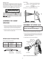
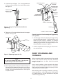
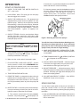
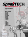
Diaphragm
Diaphragm Pumps
Pumps
1150
1150
Piston
Piston Pumps
Pumps
EP2105
EP2105
EP2205
EP2205
EP2300
EP2300
EP2300se
EP2300se
EP2400
EP2400
EP2510
EP2510
GP2605
GP2605
GP2905
GP2905
HVLP
HVLP
CS5100
CS5100
CS8100
CS8100
CS9100
CS9100
Maxum
Maxum IIII Gun
Gun
ED1150
Plus
Airless Sprayer
Owner's Manual
Model no. 0294059
Form no. 0294968C
© 1996 Wagner Spray Tech. All rights reserved.
1
CAUTION
THIS UNIT IS PROVIDED WITH A THERMALLY PROTECTED AUTOMATIC RESET. IF AN OVERLOAD
OCCURS THE THERMALLY PROTECTED AUTOMATIC RESET DISCONNECTS THE MOTOR FROM THE
POWER SUPPLY.
•
Motor will restart without warning when protector automatically resets.
•
Always disconnect motor from power supply before working on equipment.
•
When thermally protected automatic reset disconnects the motor from the power supply, relieve pressure by
turning priming valve to “prime” .
•
Turn ON-OFF switch to OFF.
CAUTION: THE CAUSE OF THE OVERLOAD SHOULD BE CORRECTED BEFORE RESTARTING.
CAUTION
Be sure to read, understand and observe all safety
precautions and warnings. See pages 3 thru 6.
Read product labels—follow manufacturer’s recommendations
All procedures and recommendations presented in this manual are based on information which SprayTECH believes
to be reliable. However, such procedures and recommendations are to be implemented and used by persons reading this
manual at their own discretion and risk.
Label directions, procedures and precautions set forth by the manufacturers of finishing products are to be considered
the best source of information on those products. No attempt has been made in this manual to provide complete data on
all the various materials which may be used in your airless sprayer.
Application procedures are presented here as suggestions only, and are not to be construed as representations or
warranties as to safety, performance, results or fitness for any intended use ot the various types of products mentioned.
BEFORE YOU CALL
Have the following information available:
Model #____________
Serial #____________
Purchase Date________________________
© 1995 WAGNER SPRAY TECH CORPORATION. ALL RIGHTS RESERVED.
2
SAFETY PRECAUTIONS
This manual contains information which must be read and understood before using the equipment. When you come to an
area which has one of the following symbols, pay particular attention and make certain to heed the safeguard.
WARNING
Important safety information indicates a hazard which may cause serious injury or loss of life.
CAUTION
Important information that tells how to prevent damage to equipment or how to avoid causes of minor injuries.
Note: Gives important information which should be given special attention.
IMPORTANT
EXTENSION CORD SELECTION
If an extension cord is used, make sure it is of the three-conductor type with NEMA connectors so a continuous grounding circuit is
provided from tool to power circuit receptacle. Also, be sure that the conductor size is large enough to prevent excessive voltage drop
which will cause loss of power. A table of recommended extension cord sizes will be found below.
For nameplate ampere ratings which are between those given, use the extension cord recommended for the NEXT HIGHER ampere
rating.
If an extension cord is to be used outdoors it must be marked with the suffix W-A following the cord type designation. For example —
SJTW-A to indicate it is acceptable for outdoor use.
RECOMMENDED EXTENSION CORD SIZES FROM SERVICE ENTRANCE TO PUMP MOTOR.
NAMEPLATE AMPERE RATING
Cord
Lgth. 0 to 5
25Ft.
18
50Ft.
18
25Ft.
18
100Ft.
18
125Ft.
18
150Ft.
18
6
18
18
18
18
18
16
7
18
18
18
18
16
16
8
18
18
18
16
16
16
9
18
18
18
16
16
14
10
18
18
18
16
14
14
11
16
16
16
16
14
14
12
16
16
16
16
14
14
3
13
16
16
16
14
14
14
14
14
14
14
14
14
12
15
14
14
14
14
14
12
16
14
14
14
14
12
12
17
14
14
14
14
12
12
18
14
14
14
14
12
12
19
12
12
12
12
12
12
20
12
12I
12
12
12
12
WARNING
HAZARD
PREVENTION
• Maximum operating range of the gun - 3000 PSI fluid
pressure.
Injection Injury - A high pressure stream of paint produced by this equipment can pierce the skin and
underlying tissues, leading to serious injury and possible amputation.
• NEVER aim the gun at any part of the body.
• NEVER allow any part of the body to come in contact
with the fluid stream. DO NOT come in contact with a
fluid stream created by a leak in the fluid hose.
• NEVER put hand in front of the gun. Gloves will not
provide protection against an injection injury.
• ALWAYS lock the gun trigger, shut fluid pump off and
release all pressure before servicing, cleaning tip guard,
changing tips, or leaving unattended. Simply turning off
the electrical power will not release pressure in the
system. The Prime Spray Valve must be turned to the
position to relieve the pressure.
• ALWAYS have the tip guard in place while spraying. The
tip guard provides some protection against injection
injuries but is mainly a warning device.
• ALWAYS remove spray tip before flushing or cleaning
the system.
DO NOT TREAT AS A SIMPLE CUT! Injectioncan lead to amputation. See a physician immediately.
• Paint hose can develop leaks from wear, kinking, abuse,
etc. A leak is capable of injecting material into the skin.
The paint hose should be inspected before each use.
NOTE TO PHYSICIAN: Injection into the skin
is a traumatic injury. It is important to treat the
injury surgically as soon as possible. DO
NOT delay treatment to research toxicity.
Toxicity is a concern with some coatings
injected directly into the blood stream. Consultation with a plastic surgeon or reconstructive hand surgeon may be advisable.
• NEVER use a spray gun which does not have a trigger
lock or trigger guard in place and in working order.
• All accessories must be rated at or above 3000 P.S.I.
(Includes spray tips, guns, extensions, and hose).
• In case of skin injection see physician immediately.
4
WARNING
HAZARD
PREVENTION
Explosion or fire - Solvent and paint fumes can explode or
ignite causing property damage and/or severe injury.
• Exhaust and fresh air introduction must be provided to
keep the air within the spray area free from accumulation
of flammable vapors.
• Avoid all ignition sources such as static electricity sparks
open flames such as pilot lights, hot objects such as
cigarettes, and sparks from connecting and disconnecting power cords and working light switches.
• Fire extinguishing equipment must be present and in
working order.
• Keep the pump away from spray area to avoid solvent
and paint fumes. The pump contains arcing parts which
emit sparks.
•
High velocity flow of material through equipment may
develop static electricity. The equipment being used,
and objects in and around the spray area, must be
properly grounded to prevent static discharge and sparks.
• Use only conductive or grounded high pressure fluid
hoses for airless applications. Be sure that gun is
grounded through hose connections.
• Power cord must be connected to a grounded circuit.
• Follow the material and solvent manufacturer's safety
precautions and warnings.
• WHEN FLUSHING EQUIPMENT use lowest possible
pressure.
5
WARNING
HAZARD
PREVENTION
Explosion hazard incompatible materials - May cause
property damage or severe injury.
• Halogenated hydrocarbon solvents such as methylene
chloride and 1,1,1 - Trichlorethane are not compatible
with aluminum and may cause an explosion. If unsure of
a material’s compatibility with aluminum, contact your
coatings supplier.
• Some spray guns and accessories cannot be used with
halogenated hydrocarbon solvents. Be certain of compatibility before use with halogenated hydrocarbon solvents.
• The SprayTECH ED1150 pump is not compatible for
use with halogenated hydrocarbon solvents. The
SprayTECH G-05, G-09, and G-10 guns must NOT be
used with halogenated hydrocarbon solvents.
Hazardous vapors - Paints, solvents, insecticides, and
other materials may be harmful if inhaled causing severe nausea, fainting, or poisoning.
• Use a respirator or mask whenever there is a chance that
vapors may be inhaled. Read all instructions with the
mask to insure that it will provide the necessary protection
against the inhalation of harmful vapors.
General - May cause property damage or severe injury.
• Read all instructions and safety precautions before
operating.
• Comply with all appropriate local, state and national
codes governing ventilation, fire prevention and
operation.
• The United States Government Safety Standards have
been adopted under Occupational Safety and Health
Act. These standards, particularly the General Standards, Part 1910 and construction Standard, Part 1926,
should be consulted.
• This high pressure airless pump is designed to be used
with authorized SprayTECH parts only. When using this
pump with parts that do not comply with the minimum
specifications and safety devices of the pump manufacturer, the user assumes all risks and liabilities.
• Before each use, check all hoses for cuts, leaks, abrasion or bulging of cover or damage or movement of
couplings. If any of these conditions exist, replace the
hose immediately. Never repair a paint hose. Replace it
with another grounded hose.
• All hoses, swivels, guns, and accessories used with this
unit must be pressure rated at or above 3000 PSI.
6
GENERAL DESCRIPTION
must also be 3-wire and 3-wire plug that will plug into a 3wire grounded electrical outlet. Do not use 2-wire extension
cords. Shorter extension cords will assure maximum
electrical power for proper operation, use more paint hose,
not more extension cords. Refer to page 3 for extension
cord selection.
Be sure to read the IMPORTANT SAFETY INFORMATION on pages 3 thru 6 before using this sprayer.
Your SprayTECH sprayer is a powerful, easy to operate
and easy to service machine. Since it operates on the
airless principle, no air compressor is needed.
Cords and extension cords should be protected from
vehicle traffic and sharp cutting edges or objects. Any worn
or damaged cords should be replaced promptly.
Power is supplied by a 3/4 horsepower, TEFC electric
motor. The flow rate is 0 to .50 gallons a minute. The
pressure is adjustable from 0 to 3000 pounds per square
inch.
The motor has an automatic overload protective switch.
This switch disconnects the motor from electrical supply if
overload occurs. The motor can be started again after 5
minutes. The cause of the overload should be corrected
before restarting.
COMPONENT FUNCTIONS
See Figure 1 for component locations.
Power for the sprayer is supplied by a 3/4 horsepower,
TEFC electric motor (see Figure 1). It is located at the rear
of the sprayer and is connected to the hydraulic pump. The
motor is furnished with a 3-wire electric cord. The third wire
(ground) should never be cut off. Any extension cords used
The motor should always be kept clean and dry. Paint acts
as an insulator. Therefore, too much paint on the motor will
cause it to overheat.
ON-OFF SWITCH
The ON-OFF switch is located on the side of the electric
motor (see Figure 1).
Hydraulic Pump
On/Off Switch
Pressure
Control
Knob
Motor
Hook
Paint
Pump
Suction Set
Priming
Knob
Inlet
Valve
Outlet
Valve
Figure 1.-Sprayer Component Locations
©1995 WAGNER SPRAY TECH CORPORATION. ALL RIGHTS RESERVED.
7
HYDRAULIC PUMP
PAINT PUMP
For the hydraulic pump location, see Figure 1. It operates
as follows: The electric motor is connected to the eccentric
bearing, which is inside the hydraulic pump. The piston
rests on the bearing. The movement of the bearing causes
the piston to move up and down. When the trigger on the
gun is pulled back, this action moves the pump diaphragm.
Diaphragm movement forces the paint through the outlet
valve and out the paint hose and spray gun. The paint goes
through the spray gun at high pressure, causing it to breakup (atomize) into fine particles. This gives a smooth and
even paint coating. Pressure and delivery rate are regulated by the pressure control knob and spray tip size.
The paint pump is located below the hydraulic pump (see
Figure 1). The two pumps are bolted together by four
socket head capscrews. The diaphragm separates the
pumps. The paint pump operates as follows: The piston in
the hydraulic pump forces hydraulic oil toward and away
from the diaphragm. This action moves the diaphragm up
and down. Diaphragm movement forces paint through the
spray gun at high pressure.
PRESSURE CONTROL KNOB
The pressure control knob controls the pressure control
valve. It is manually operated. It is located on the front of the
hydraulic pump near the bottom of the sprayer (see Figure
1). When the knob is turned cIockwise, more hydraulic
pressure is directed toward the diaphragm. When the knob
is turned counterclockwise, less hydraulic pressure is
directed toward the diaphragm. The pressure control knob
regulates the pressure on the diaphragm from 0 PSI when
turned fully counterclockwise to 3000 PSI when turned
fully clockwise.
INLET VALVE
The inlet valve is located on bottom of the paint pump at the
front of the sprayer (see Figure 1). The suction nut end of
the suction tube screws onto this valve. The valve operates
automatically. It controls the flow of paint from the paint
container into the paint pump. It does this by opening up
when the piston and diaphragm are on the downstroke,
allowing a “gulp” of paint to enter the paint pump. The inlet
valve then closes when the piston and diaphragm are on
the upstroke. This closing prevents paint from going back
through the inlet valve into the paint container (inlet valve
acts as a check valve). Instead, the paint is directed out the
spray hose and spray gun by the outlet valve.
NOTE
DO NOT START PUMP UNDER PRESSURE. REDUCE PRESSURE TO ZERO BY TURNING PRIMING
KNOB TO PRIME POSITION . FAILURE TO DO SO
WILL DECREASE MOTOR LIFE.
The inlet valve is a one-piece configuration. It contains a
device to dislodge a stuck valve by simply pushing the
plunger button on the side of the valve body.
DIAPHRAGM
CAUTION
The diaphragm is the heart of the sprayer. In addition to
pumping paint, it also serves as a gasket between the
hydraulic pump and paint pump. As such, it prevents the
paint and oil from mixing. The sprayer operates at 1725
strokes per minute. This means that the diaphragm forces
a “gulp” of paint out of the spray gun 1725 times every
minute.
The plunger button should never be pushed during
operation as this may cause premature failure of the
inlet valve.
OUTLET VALVE
An insert fits in the inlet hole on the underside of the paint
pump. This insert reduces wear by protecting the diaphragm from the metal edges of the inlet hole.
The outlet valve is also located on bottom of the paint pump
at the front of the sprayer (see Figure 1). It operates
automatically, serving as a check valve. When the priming
valve is on
(spray) position, the outlet valve directs the
flow of paint out into the spray hose and into the spray gun.
When the diaphragm and piston act to “gulp” more paint,
the outlet valve closes. The closed valve prevents (checks)
paint in the spray hose and spray gun from returning to the
paint pump.
The diaphragm is made of flexible, tough plastic. It is not
harmed by common solvents.
NOTE
The diaphragm should be replaced whenever the paint
pump is removed. Using the old diaphragm will result in
limited diaphragm life and fluid leaks.
8
The outlet valve also contains a device to dislodge a stuck
valve. Simply push the plunger button located on the side
of the paint block before starting the pump.
SUCTION SET
The complete suction set consists of (1) the suction tube
with a suction filter on one end and (2) the return tube (see
Figure 1). Both suction and return tube are chemical and oil
resistant. One end of the suction tube and one end of the
return tube screw onto the paint pump (see Figure 1).
These two fittings need to be tight enough to keep air from
being drawn in. The other two ends go in the paint container. When the priming knob is turned to
(prime), paint
is drawn up the suction tube into the paint pump. The paint
pump then routes the paint through the return tube back to
the paint container. This primes the painting system. When
(spray), flow is shut off
the priming knob is turned to
through the return tube and the sprayer can spray.
CAUTION
The plunger button should never be pushed during
operation as this may cause premature failure of the
outlet valve.
You can see that the inlet valve and outlet valve work in
harmony with the diaphragm and piston. As a" team" they
pump paint.
PRIMING KNOB
The priming knob controls the priming valve. It is located on
the right front of the paint pump at the front of the sprayer
or
(see Figure 1). It can be manually turned to the
position. When on
(prime) it serves to rid the sprayer of
air by directing the initial air volume of the inlet valve back
into the paint container. It will continue to do this until paint
comes through and it is manually switched to the
(spray) position. It then directs the paint out the outlet fitting
to the spray hose and on to the spray gun.
NOTE:
DO NOT USE THE SPRAYER UNLESS
THE SUCTION FILTER IS IN PLACE!
HIGH PRESSURE OUTLET FITTING
The high pressure outlet fitting is located on the front side
of the paint pump (see Figure 1). The paint hose is connected to it. The outlet fitting connections must be very tight.
Otherwise, fluid will leak out the connections when pressure builds up in the system.
The priming valve also serves to relieve pressure on the
system during shutdown and cleanup. The pressure is
relieved by turning the priming knob to .
PAINT HOSE
The high pressure paint hose (see Figure 1) has permanently swaged fittings. It is grounded with a static conductor. This conductor serves to “drain off” any static charge,
preventing shock. The conductor is sandwiched between
two insulating sheaths which resist breaking and abrasion.
WARNING
CAUTION
DO NOT IMMERSE THE PAINT HOSE IN ANY
SOLVENTS.
CHANGE THE POSTION OF THE PRIMING KNOB
SLOWLY. THIS WILL PREVENT BREAKING ANY VALVE
PARTS. ALWAYS REDUCE THE PRESSURE WITH
THE PRESSURE CONTROL KNOB BEFORE TURNING
THE PRIMING KNOB.
The paint hose and the electric cord should always be
protected from vehicle traffic and sharp cutting edges
or objects. If the paint hose is cut, worn, or damaged it
must be replaced with another high pressure grounded
hose.
The paint hose can develop leaks from wear, kinking,
abuse, etc. A leak is capable of injecting spray material
into the skin. Therefore, the paint hose should be
inspected periodically. Never repair a paint hose —
replace it with another high pressure grounded hose.
9
Spray Pattern
Width = 2 x Spray Pattern Width Number
e.g. 0153319 = 2 X 3 = 6” Spray Pattern 1 Foot
from Work
0153419= 2 x 4 = 8” Spray Pattern 1 Foot
from Work
See Figure 2 for example of a spray pattern.
SPRAY GUN
The spray gun is connected to the sprayer by the paint
hose. The gun will spray when the unit is running, the
suction and return tubes are in the spray material, the
the pressure control valve
priming knob is turned to
is adjusted, and the spray gun trigger is pulled back.
WIDTH OF SPRAY
PATTERN IN INCHES
WARNING
THE SPRAYTECH ED1150 PUMP IS NOT COMPATIBLE
FOR USE WITH HALOGENATED HYDROCARBON SOLVENTS. THE WAGNER G-05, G-09 AND G-10 GUNS
MUST NOT BE USED WITH HALOGENATED HYDROCARBON SOLVENTS.
ASSEMBLY OF A NEW
SPRAYER
1'
Figure 2.-Example of Spray Pattern
ASSEMBLY OF SPRAY GUN
1. Screw the return fitting into the elbow on the front side
of the paint pump. Both fittings should be hand tight only,
but tight enough to prevent air from being drawn in.
NOTE
Follow the Assembly Instructions that came with
your gun if it is a brand other than Wagner.
2. Screw the paint hose, wrench tight, onto the outlet fitting
on the front side of the paint pump.
After you have selected the proper spray tip, assemble it
onto the spray gun as explained in Steps 1 through 4.
1. lnsert the spray tip and sealing washer into the tip guard
so that the flats of the spray tip are seated perfectly into
the tip guard. See Figure 3.
2. Hand tighten the tip nut onto the diffuser.
SPRAY GUN TIP SELECTION
SPRAY GUN
DIFFUSER
SEALING WASHER
Select a spray gun tip as follows:
SPRAY TIP
LACQUERS &
STAINS
0153315
0153415
ENAMELS
0153317
0153417
LATEX
0153319
0153419
TIP NUT
Example 0153 3 19
0153
Prefix
3
Spray Pattern
Width In Degrees
(In this case, 30°)
19
Size of Spray Tip
Holes In Inches
(In this case,.019")
TIP GUARD
Figure 3.-Spray Tip Assembly Sequence.
10
TRIGGER SAFETY
LEVER
3. Loosen the tip nut slightly. Turn the tip guard about
1/16 turn counterclockwise from desired spray angle.
See Figure 4.
SPRAY GUN
HOUSING
TENSION NUT
LOCKED OFF
(WILL NOT
SPRAY)
TIGHTEN WITH
WRENCH FROM
THIS POINT
SEALING
WASHER
LOCKED ON
(CLEANING ONLY)
FILTER
DESIRED SPRAY
ANGLE
UNLOCKED
(SPRAY AS DESIRED)
Figure 4.- Spray Gun Tip Guard Postion Before
Tightening.
HANDLE
CONNECT SPRAY GUN HOSE
4. Tighten tip nut. The tip guard should now be in the proper
position. See Figure 5.
Figure 6.-Spray Gun Filter Assembly and Trigger Safety
Lever position.
TIP GUARD
6. Test the trigger tension by unlocking the trigger safety
lever and pulling back trigger. To increase tension, turn
tension nut (see Figure 6) clockwise. To decrease
trigger tension, turn tension nut counterclockwise. After
adjusting trigger tension, lock trigger safety lock in
locked off position as shown in Figure 6.
7. Connect the paint hose to the spray gun. This connection should be tight.
TIP NUT
PAINT STRAINING AND
THINNING
Figure 5.-Tightening Spray Gun Tip.
When a container of paint is exposed to the air for a period
of time, “skin” may form on top. This “skin” should be
removed. If necessary, the paint should be strained
through a strainer.
NOTE
Do not try to change the angle of the tip guard
unless the tip nut has been loosened.
Under normal conditions, paints used with this airless
sprayer do not have to be thinned. However, it is possible
that you may use paint that is too thick to be sprayed. In this
case you will have to thin the paint.
5. Put the spray gun filter on the gun as shown in Figure 6.
First remove the handle from the spray gun housing.
Stick the small end of the filter firmly in the spray gun
housing. Then screw the handle back on. See Page 26
for Optional Filters.
When thinning paint to spraying consistency (viscosity),
use the right thinner — water for latex paints, mineral spirits
for oil base paints (or, see the instructions on the paint
container for proper thinner).
11
a few minutes. It is sometimes helpful to turn ON-OFF
switch ON and OFF to assit in bleeding.
OPERATION
START UP PROCEDURE
B. Now turn pressure control knob clockwise to prime
the pump. When sprayer is primed, paint will come out
of the return tube. This may take 2-3 minutes. If
sprayer does prime, turn pressure control knob
counterclockwise and repeat procedure.
1. CHECK TO BE SURE THE MOTOR SWITCH IS
OFF— play it safe.
2. LOCK SPRAY GUN—The spray gun will not spray
when the trigger lock is locked.
PRESSURE CONTROL
VALVE KNOB
3. CHECK THE HYDRAULIC OIL— The sprayerer was
shipped with the proper amount of hydraulic oil in the
hydraulic pump. However, the oil should be checked
before starting. Look at oil level in oil fill port. When the
unit is level, oil level should be at bottom of fill port. Use
only hydraulaic oil part number 0088009 - 1 quart or
part number 0088010 - 1 gallon. Oil capacity is 19
ounces.
4. CHECK FITTINGS—Check to see that these fittings
are tight: inlet valve, return tube, outlet valve, outlet
fitting, high pressure airless hose, spray gun and allen
head paint pump screws.
Figure 7.-Bleeding Air Out of the Sprayer.
You will also have to follow the above bleeding procedure when you change hydraulic oil, if you remove the
paint pump or work on the hydraulic housing, or if the
sprayer loses prime due to rough handling.
NOTE
DO NOT TIGHTEN PAINT PUMP SCREWS TO MORE
THAN 15 FOOT-POUNDS TORQUE (180 INCHPOUNDS)
11. MAKE SURE PRESSURE IS REDUCED BY TURNING THE PRESSURE CONTROL KNOB COUNTER
CLOCKWlSE.
5. TURN PRIMING KNOB TO (PRIME) POSITION— A
will appear in the priming knob window. The sprayer
must be primed before it will spray.
12. TURN PRIMING KNOB TO
(SPRAY) POSITION
—
will appear in the knob window.
6. Make sure the suction tube is immersed in paint.
13. UNLOCK SPRAY GUN TRIGGER — When the trigger
is unlocked, the trigger safety lever will point in the
same direction as the trigger (see Figure 6).
7. PLUG ELECTRIC CORD INTO OUTLET— Electric
service must be 115 VAC, 60 Hz. REMEMBER: More
than 100 feet of extension cord is not recommended.
Use additional airless paint hose, not more electric
cord.
14. ADJUST PRESSURE — Adjust the pressure control
knob on the sprayer to lowest pressure needed for good
operation. Pull spray gun trigger back and spray a test
area to check spray pattern.
8. TURN THE MOTOR SWITCH ON.
9. PRIME THE PUMP—Let the paint circulate until no air
bubbles show in the paint (aboutt 2-3 minutes). Turn
the pressure control valve at least 1/2 turn clockwise
from fully decreased postion to prime the pump with
paint.
15. YOU ARE NOW READY TO SPRAY — See “SPRAY
PAINTING” for tips on how to spray.
SPRAY PAINTING
You can learn to spray paint as easy as you can learn to
paint with a brush or roller. You can get a professional
looking job in a safe manner by following the spray painting
tips below.
10. BLEED THE AIR—If unit fails to prime when started up,
it may be necessary to bleed (vent) the air out of the
hydraulic system. Bleed the air as follows:
A. Turn pressure control knob all the way counterclockwise, turn priming knob to , and let sprayer run
1. Heed all WARNINGS and CAUTIONS that are listed on
pages 2 thru 6 at the front of this manual. Take time out
now to reread them.
© 1995 WAGNER SPRAY TECH CORPORATION. ALL RIGHTS RESERVED.
12
2. Avoid sharp bending and kinking of the paint hose. The
paint hose and electric cord should be kept clear of traffic
and sharp cutting edges or objects.
6. Keep the spray gun perpendicular to the work as shown
in Figure 10.
APPROXIMATELY
10 TO 12 INCHES
3. Use the lowest pressure possible when spraying. Too
much pressure shortens equipment life. It also causes
faster than normal wear on the spray tip.
RIGHT
WAY
4. Determine the best spraying distance (distance from
spray tip on the spray gun to the work). If the spray gun
is held too close to the work, you will have paint buildup
that will cause sags and runs. If the spray gun is held too
far from the work, “fogging” will result.
WRONG
WAY
The correct distance should be about 10 to 12 inches.
Keep this distance for the entire length of the stroke. Of
course, the shape of some work surfaces will not permit
this. However, the same spraying distance should be
kept whenever possible.
Figure 10.-Right and Wrong ways to Hold Spray Gun
Toward Work.
5. Do not move the spray gun by flexing your wrist. The
result of this is shown in Figure 8. Rather, move the
spray gun with a smooth stroke of the entire arm and
shoulder. Maintain the same arm speed all the way
through the stroke. The result of this is shown in Figure
9.
LIGHT
COAT
HERE
HEAVY
COAT
HERE
7. The spray gun should be triggered (turned off and on) on
each stroke. This will save paint and avoid paint buildup
at the end of the stroke. However, do not trigger during
the middle of a stroke. This will result in an uneven spray
and splotchy work. See Figure 11 for proper triggering
on a left-to-right stroke. Reverse for a right-to-left stroke.
LIGHT
COAT
HERE
8. Move the spray gun at a rate of speed that is comfortable
for you. If you have to move your arm too fast in order
to prevent excessive paint buildup, either (1) lower the
pressure by turning the pressure control knob counterclockwise, or (2) use a spray tip with a smaller hole. If
you have to move your arm too slow in order to get a
good coating, either (1) raise the pressure by turning the
pressure control knob clockwise, or (2) use a spray tip
with a larger hole. You should always keep the spray
gun moving when making a stroke. Slowing down in one
place will cause sags or runs.
WRONG
WAY TO SPRAY
Figure 8.-Result of Flexing Wrist While Spraying.
APPROXIMATELY
10 TO 12 INCHES
EVEN COAT ON WORK THROUGH
STROKE MOVEMENT OF ENTIRE ARM
APPROXIMATELY
10 TO 12 INCHES
WORKING
DISTANCE
PULL
TRIGGER
WORK
EVEN
STEADY
STROKE
RELEASE
TRIGGER
Figure11 -Proper Way to Trigger Spray Gun.
STEADY
ARM
SPEED
RIGHT
WAY TO SPRAY
Figure 9.-Result of Smooth Arm Stroke and Steady,
Even Speed While Spraying
9. Overlap each stroke by about 40% to 50%. The overlap
will insure a paint coating that is uniform across the work.
One way to get good overlap is to point the spray
gun at the edge of the last stroke.
13
To remove and replace the filter, proceed as follows:
1. Lock spray gun trigger OFF.
SPRAY TIP PLUGGING
The spray tip can be plugged by foreign matter and “skin”
in the paint. Excessively large paint pigments can also plug
the tip. If the tip becomes plugged while spraying, proceed
as follows:
2. Turn sprayer ON-OFF switch OFF.
TOP OF FILTER
1. Lock spray gun trigger OFF so that the spray gun can't
spray.
2. Turn sprayer ON/OFF switch OFF.
PIN HOLE
3. Reduce pressure by turning the pressure control knob
counterclockwise. Turn priming valve knob to
to
bleed pressurized paint in paint hose and spray gun
back into paint container.
Figure 12.-Example of Pinhole in Spray Gun Filter.
4. Remove tip guard assembly with spray tip and sealing
washer from spray gun as shown in Figure 3, page 10.
3. Reduce pressure by turning the pressure control knob
counterclockwise. Turn priming knob to
. This will
drain the pressurized paint in the paint hose and spray
gun back into the paint container.
5. Remove spray tip and sealing washer from tip guard
assembly.
4. Remove the paint hose from the spray gun as shown in
Figure 13.
6. Soak tip guard assembly, spray tip, and sealing washer
in solvent. Then clean them with a stiff brush. A toothpick, wood chip, or sharpened matchstick can be used
to clean the spray tip hole.
5. Remove the handle from the spray gun.
6. Remove the old filter. Use a new filter, or clean the old
filter.
7. Stick small end of new or cleaned filter into spray gun
housing.
CAUTION
8. Screw handle back on spray gun.
Never clean the spray tip hole with a wire or metal
object as these items will cause damage.
9. Connect paint hose to spray gun.
Extra spray gun filters should be kept on hand.
7. Reassemble the spray tip, sealing washer, and tip guard
assembly onto the spray gun the same way you did
when you assembled the unit. See “ASSEMBLY OF
SPRAY GUN”, page 10.
SPRAY GUN HOUSING
HANDLE WASHER
SPRAY GUN FILTER CLEANING AND
CHANGING
FILTER
Clean or change the spray gun filter at least once per
painting day, some types of latex paint may require filter
cleaning or changing more often.
HANDLE
The filter is best cleaned with a brush dipped in appropriate
solvent. Never poke the filter with a sharp instrument.
If the filter is not cleaned or changed at the proper time, it
will plug from the top down. When there is about 1 inch or
so of the filter left that isn’t plugged, the heavy flow of paint
will blow pinholes in the filter. An example of this is shown
in Figure 12.
PAINT HOSE
Figure 13.-Spray
Replacement.
14
Gun
Filter
Removal
and
10. Remove suction hose from inlet valve and let valve
suck in a small amount of light oil. This will oil pump parts
and keep them from corroding.
SHUTDOWN AND CLEANUP
You should clean and oil your sprayer as soon as you finish
a job. Do not store the sprayer unless it has been
cleaned and oiled.
CAUTION
When you shut down, clean up with water if you were using
latex paint and clean up with solvent if you were using oil
base paint.
It is very important that you oil the inlet valve as stated
in step 10 above. Oil inlet valve after EVERY job.
If you are going to stop spraying for an hour or two just
relieve the pressure in the sprayer by turning the priming
knob to , cover your paint container to keep dirt out and
place tape over the spray tip to keep air from drying paint in
the tip.
11.Turn ON-OFF Switch OFF.
MAINTENANCE
Shut down and clean up as follows:
Check the hydraulic oil level before each use and after
every 20 run hours. To check hydraulic oil level, see
number 3, 'CHECK THE OIL", Page 12.
1. Reduce pressure by turning pressure control knob counterclockwise. Turn priming knob to . Remove suction
hose only from paint container, hold it above container
and allow sprayer to pump itself dry. Remove tip guard,
spray tip and washer and let soak clean.
Change the hydraulic oil after the first 20 run hours and
every 200 hours thereafter. To change hydraulic oil, proceed as follows:
2. Have container of hot soapy water for cleaning after
spraying with latex paint or suitable solvent for oil base
paints. Do not clean with mineral spirits if using latex
paint because it makes jelly.
1. Remove the oil filler plug from the hydraulic housing face
plate.
2. Drain out the old hydraulic oil.
3. Place suction and return tubes in the solvent or warm
soapy water. Increase pressure and let circulate for
2-3 minutes.
3. Fill hydraulic housing with approximately 19 ounces of
hydraulic oil. Use only hydraulic oil part number 0088009
(1 quart) or part number 0088010 (1 gallon). Replace oil
fill plug.
4. To save remaining paint in spray hose, carefully trigger
gun into and against side of paint container. Be careful
of splashing. Turn priming knob to . Turn pressure
up and watch inside of container for cleaning solvent to
come through, then shut off gun and place in cleaning
container.
4. Since air may enter the system when the oil is changed,
the sprayer may have to be vented (bled). To bleed out
the air, see number 10, 'BLEED THE AIR", Page 12.
You will also have to bleed the air out of the system if
you remove the paint pump or go into the hydraulic
housing, or if the sprayer loses prime due to rough
handling.
5. Trigger gun and let cleaning solvent circulate for approximately 2-3 minutes.
IMPORTANT!
6. Turn priming knob to and shut unit off. Unscrew gun
handle. Remove and clean filter. Install filter in gun and
reassemble spray tip, washer and guard.
Tighten the (4) Pump Block Bolts after the first 20 hours
of use.
7. With priming knob on , remove suction tube from
cleaning container to allow sprayer to pump dry.
D
C
8. Take a clean container of water or solvent and using low
pressure pump through system until clear. If cleaning
with water, turn to and pump lacquer thinner through
pump. This will clean any paint particles still in the
system and remove water.
A
B
To tighten, use the 6mm allen wrench supplied in the
literature kit. Use a criss cross pattern when tightening.
First A, then C, then B, then D. If you have a torque wrench
use 13-15 Ft./Lbs.
9. Take suction tube out of container and let sprayer run
itself dry.
©1995 WAGNER SPRAY TECH CORPORATION. ALL RIGHTS RESERVED.
15
SUCTION FILTER CLEANING
CHECKING OPERATION OF OUTLET
VALVE
The suction filter is located on the end of the suction tube.
A clean suction filter gives full delivery capacity and a
constant level of spraying pressure. Clean the suction filter
as needed with a brush dipped in solvent.
The outlet valve should be checked if the sprayer draws up
little or no paint, or draws up paint, but doesn’t build
pressure. It is a good practice to check outlet valve operation before spraying. If the sprayer has been in storage, the
outlet valve may be sticky.
CHECKING OPERATION OF INLET VALVE
To check outlet valve operation, proceed as follows:
See Figure 14 for location of inlet valve. The inlet valve
should be checked if the sprayer draws up little or no paint.
It is a good practice to check inlet valve operation before
spraying. If the sprayer has been in storage, the inlet valve
may be sticky.
1. Turn priming knob to
2. Turn ON-OFF switch to ON.
3. If above symptoms occur during priming of pump simply:
To check inlet valve operation, proceed as follows:
1. Turn priming knob to
.
• Reduce pressure to 0.
.
• Push the plunger in and out to lift the ball off the seat.
See Figure 14.
2. Turn ON-OFF switch ON.
3. Let inlet valve suck against the palm of your hand. If little
or no suction is felt repeatedly move the plunger in and
out to lift inlet valve stem, as shown in Figure 14. Put in
a few drops of light oil or cleaner.
CAUTION
THE PLUNGER DEVICE MUST BE LOOSENED PRIOR
TO ANY SERVICE OF THE OUTLET VALVE.
NOTE
Your sprayer was shipped with two extra outlet valve
springs. Periodic replacement is necessary to maintain
top performance. Suggested replacement is every 35 to
50 hours of operation for best performance. Perodic
replacement of the outlet valve spring also increases the
life of the inlet valve.
INLET VALVE PLUNGER
OUTLET VALVE
PLUNGER
Figure 14.-Inlet & Outlet Valve Plungers
16
5. Install the new diaphragm. Put the membrane stem and
nut side of the diaphragm in the hydraulic pump housing
hole.
REPLACING DIAPHRAGM OR
DIAPHRAGM PARTS
6. Put the paint pump back on. Before installing the 4 paint
pump screws, put Anti-Seize Lubricant on the screw
threads. (This prevents the steel screws from galling
and seizing in the aluminum hydraulic pump). Now
install the 4 new paint pump washers and 4 screws using
a 6 millimeter allen wrench (see Figure 17).
The diaphragm is the only separation between the paint
pump and the hydraulic pump. It pumps paint, but it also
serves as a gasket between the hydraulic pump and paint
pump. If the diaphragm membrane ruptures, paint will
probably get into the hydraulic housing. If adequately
cleaned up soon enough, the parts (bearing, piston, etc.)
can be saved. If the hydraulic housing is not cleaned up
soon enough, you may have internal freeze-up.
PAINT
PUMP
SCREW
D
When the diaphragm or diaphragm parts have to be replaced, proceed as follows:
B
A
1. Remove the 4 paint pump screws with a 6 millimeter
alIen wrench. As you remove the 4 screws, also remove
the 4 washers that may remain in the holes.
C
Figure 17-Tightening Paint Pump Screws.
7. Tighten opposite screws in turn as shown. (A-B, C-D).
Tighten screws evenly to 13-15 ft lbs. (156-180 inchpounds) torque. Begin at screw A tightening to 10 ft lbs.
continue to screw D. Repeat this step until all screws
have attained a torque of 10 ft. lbs. Repeat sequence
tightening to 14 ft lbs. and repeat one more time tightening to 14 ft lbs. Following this tightening sequence will
assure proper seating of the diaphgram.
Figure 15. - Remove paint pump screws
2. Take the paint pump housing off the hydraulic pump
housing.
NOTE:
Improper torquining sequence of the paint pump screws may
cause damage to diaphragm and inefficient pump performance.
Proper torque also prevents hydraulic oil from leaking out
between the paint pump and the hydraulic housing. It is
recommended that a new unit be re-torqued after the first 20
hours of operation. Thereafter, tighten the paint pump screws
after every 3 or 4 operations. One lockwasher should always be
used with each of the four paint pump screws.
3. Remove the old diaphragm and the old insert ring.
DIAPHRAGM
8. After replacing or repairing the diaphragm, the sprayer
will have to be bled. See Number 9, “BLEED THE AIR,”
page 12.
PAINT PUMP
USE OF ANTI-SEIZE LUBRICANT
You should use Anti-Seize Lubricant (part number 0093930)
any time you are screwing dissimilar metal thread connections together. On your sprayer these connections are; (1)
steel outlet valve into paint pump, (2) steel inlet valve into
paint pump, (3) steel priming valve into paint pump, (4) steel
paint pump screws into aluminum hydraulic pump, and (6)
steel pressure control valve into iron pressure vessel/hydraulic pump.
PAINT PUMP SCREW
Figure 16.-Diaphragm Parts and Their Relationship to
Other Parts of the Sprayer.
4. When a new diaphragm is installed, a new insert ring
(see Figure 16) should also be installed. Install the new
Insert. Be sure to put the flat surface of the insert ring into
the flat surface of the paint pump.
©1995 WAGNER SPRAY TECH CORPORATION. ALL RIGHTS RESERVED.
17
TROUBLESHOOTING
Provided you have followed the instructions, the sprayer will operate efficiently and give trouble-free service. Should any
unexpected problem arise you can, in most cases, remedy the problem by following the chart below.
Problom
Sprayer does not startup
Remedy
Cause
1. Sprayer not plugged in
2. Blown fuse in circuit
3. No voltage or low voltage at
wall plug
4. Bad sprayer ON-OFF switch
5. Damaged cord or extension
cord, or cord capacity too low
6. Defective motor
Sprayer starts up but
does not draw up paint
1. No paint or suction tube not
totally immersed in paint
2. Suction filter clogged
3. Suction tube loose at inlet
valve
4. Suction tube damaged or defective
5. Priming valve plugged
6. Hydraulic oil level very low or
empty
7. Inlet valve stuck
8. Inlet valve damaged (paint is
drawn up and leaks through
inlet valve)
9. Outlet valve stuck
10. Diaphragm membrane
ruptured, broken diaphragm
spring, cracked diaphragm
disk, or loose diaphragm nut
11. Loose oil suction tube in hydraulic housing
12. Scored piston or cylinder
13. Wrong grade of hydraulic oil, or
using fluid other than hydraulic
oil
14. Rear motor fan cover bent
Sprayer draws up paint
but pressure does not
build up
1. Priming valve defective (paint
runs back via return hose)
2. Hydraulic oil level low
3. Diaphragm membrane
ruptured, cracked diaphragm
disk, broken diaphragm spring,
or loose diaphragm nut
4. Outlet valve stuck, dirty, or has
worn parts
5. Defective suction tube
6. Scored piston or cylinder
7. Cracked hydraulic housing or
paint pump housing
18
1. Plug in
2. Replace fuse
3. Test power supply voltage
4. Replace switch
5. Replace with 3-prong cord. Any extension cord
used must be 3-wire, 12 gauge minimum, with a 3wire plug that will plug into a 3-wire electrical outlet.
6. Repair or replace. Take to SprayTECH Authorized
Service Center.
1. Add more paint or immerse suction tube in paint
2. Clean or replace filter
3. Clean connection and tighten firmly
4. Replace tube
5. Take valve off and clean it
6. Fill only with hydraulic oil part number 0088009
(quart) or 0088010 (gallon). Caution: do not
overfill
7. Push Inlet Valve Plunger to free stuck valve
8. Replace inlet valve
9. Push Outlet Valve Plunger to free stuck valve
10. Clean hydraulic housing if needed (blown diaphragm may cause internal freezeup). Replace
defective diaphragm parts or tighten nut if loose
11. Replace tube
12. Replace piston. If cylinder is scored, replace
hydraulic housing
13. Use only hydraulic oil part number 0088009
(quart) or 0088010 (gallon). Change initial fill after
first 20 hours of operation. Change every 200
hours there after. Bleed after changing
14. Remove fan cover and straighten
1. Replace valve
2. Fill to appropriate level using only hydraulic oil part
number 0088009 (quart) or 0088010 (gallon)
3. Clean hydraulic housing if needed. Replace
defective diaphragm parts or tighten nut if loose
4. Dismantle valve. Clean or replace valve spring first.
If this does not work, replace ball
5. Replace tube
6. If piston is scored, replace piston. If cylinder is
scored, replace hydraulic housing
7. Replace housing
TROUBLESHOOTING (Continued)
Problem
Cause
Remedy
Sprayer draws up paint,
pressure builds up, but
drops away markedly
when gun is opened (low
performance)
1.
2.
3.
4.
1.
2.
3.
4.
No spray tip on gun
Spray tip hole too large
Suction filter clogged
Gun filter plugged
5. Gun filter too fine for
coarse paint being
sprayed
6. Suction tube not firmly
tightened to inlet valve
7. Leaky suction tube
8. Leaky priming valve
9. Worn paint pump outlet
valve seat, ball, or
spring
10. Worn Inlet valve
11. Pressure control valve
worn or damaged
Pressure fluctuation
.
1. Loose suction tube at
inlet valve
2. Leaky suction tube at
inlet valve
3. Leaky or dirty priming
valve
4. Leaky, worn, or damaged inlet valve
5. Outlet valve may be
stuck, dirty, or have
worn parts
6. Dirty pressure control
valve
7. Worn or damaged pressure control valve
8. Pinhole in diaphragm
membrane
9. Loose oil suction tube,
causing air in hydraulic
system. Or, oil suction
tube may be partly
plugged
10. Eroded paint pump
block
11. Cracked hydraulic
housing
Paint in hydraulic housing
1. Ruptured diaphragm
membrane
Spray gun won't shut off
1. Insufficient trigger
spring pressure on gun
2. Worn ball or diffuser
seat or gun
3. Foreign matter or paint
buildup between ball
and diffuser on gun
19
Put on correct tip
Select smaller tip or try newer tip
Clean or replace filter
Clean or replace filter every 4 hours. Keep
extra filters on hand
5. Use correct filter or strain/thin paint
6. Clean connection thoroughly and tighten
7. Clean connection thoroughly and tighten
or replace tube
8. Replace valve
9. Replace defective part(s)
10. Replace valve
11. Replace valve - Take to Authorized
SprayTECH Service Center
1. Clean connection thoroughly and tighten
2. If tightening doesn’t work, replace suction
nut and adapter
3. Clean or replace valve
4. Replace valve
5. Dismantle valve. Clean or replace valve
spring first. If this doesn’t work, replace
ball
6. Take to Authorized SprayTECH Service
Center
7. Take to Authorized SprayTECH Service
Center
8. Replace diaphragm membrane
9. Clean oil suction tube if necessary and
reglue
10. Replace block
11. Replace housing
1. Take to Authorized SprayTECH Service
Center
1. Increase trigger spring pressure by
adjusting rear tension nut
2. Replace ball or diffuser or gun
3. Disassemble gun and clean
TROUBLESHOOTlNG (Concluded)
Problem
Remedy
Cause
Spray gun leaks
1. Worn valve ball holder on
gun
1. Replace valve ball holder
Spray gun won't spray
1. Out of spray material
2. Spray tip or gun filter
plugged
1. Get more spray material
2. Clean spray tip. Clean or replace gun filter
Low paint output from spray
gun
1. Partially plugged spray tip or
filter
1. Clean or replace gun filter. Clean spray tip
Spray gun sprays without
trigger being pulled back
1. Valve ball holder not in
correct position
1. Adjust rear tension nut. If this doesn’t work, examine
valve ball holder and replace if necessary
NOTE1: If a return line that is completely submerged in
paint causes bubbles after priming, you probably have a
vacuum leak in the suction set. To remedy, tighten suction
set.
NOTE 3: More than 100 feet of extension cord is not
recommended. Use more paint hose, not more extension
cord. Shorter extension cords will assure maximum electrical power for proper operation.
NOTE 4: When the priming valve is on
(spray) and you
are getting flow back through the return tube, remove
priming valve and clean or replace.
NOTE 2: Should oil seep through the face of the hydraulic
and paint pump sections, firmly tighten the four sockethead capscrews. Use the 6 millimeter alIen wrench. Follow
the procedure described in Item 8, page 17.
NOTE 5: The electric motor should always be kept clean
and dry. Paint acts as an insulator. Therefore, too much
paint on the motor will cause it to overheat.
BEFORE YOU CALL
Have the following information available:
Model #____________
Serial #____________
Purchase Date________________________
©1995 WAGNER SPRAY TECH CORPORATION. ALL RIGHTS RESERVED.
20
6
7
4
3
5
2
8
11 12
13
9
14
1
15
10
17
41
40
39 38 37
16
18
36
21 20
19
23 22
43
42
35
24
34
33
5
25
32
26
31
27
1
28
30
29
FINAL ASSEMBLY — Figure 18
ITEM PART NO.
DESCRIPTION
1
2
3
4
5
6
7
8
9
10
11
12
13
14
15
16
17
18
19
0288478
0294511
0088328
9800325
0089935
0270504
0294656
9822515
0270501
0005311
0089937
0294513
9800049
0034307
9871044
0270488
0047393
0288775
0089504
20
21
22
294265
0089501
0089829
Grip,
Handle
Washer, Lock, 5/16"
Screw, Soc. Hd. 8mm x 16mm Lg.
Elbow, Barb
Tubing, 5/16" O.D., 3/16" I.D.
Filter
Ring, Retaining
Washer
Spring
Gasket
Cover
Screw
Cap, Filter
O-Ring
Piston
Ring, Retaining
Knob, Pressure Valve
Valve, Pressure Assembly
(Includes Item 21)
Bearing with Eccentric
O-Ring
Key, Woodruff
QTY.
1
1
4
1
2
1
1
1
1
1
1
1
1
1
1
1
1
1
1
1
1
1
©1995 WAGNER SPRAY TECH CORPORATION. ALL RIGHTS RESERVED.
21
ITEM PART NO.
DESCRIPTION
23
24
25
26
27
0047487
0089934
------9885552
-------
28
29
30
31
32
33
34
35
36
37
38
39
40
41
42
43
0089945
0294533
0090497
0090559
0089726
9802533
0294495
0089932
0270490
0270524
------0089986
0089985
0294530
0089453
0089799
Washer, Copper
O-Ring
Diaphragm Assembly, See Fig. 19
Elbow
Paint Pump Assembly
(See Figure 19)
Screw, Soc. Hd. Cap, M8 x 80
Foot, Rubber
Nut, Hex. 5/16"- 18
Cord, Power
Clamp, Cord Locking
Bolt, Carriage, 5/16" x 18 x 1
Vessel, Pressure
O-Ring
Bearing, Ball
Seal, Tip
Nut, (Included with Item 43)
Plate, On-Off
Washer, Internal Tooth
Motor
Switch, Electric
Terminal, Insulated
QTY.
1
3
1
1
1
4
4
1
1
1
1
1
1
2
1
1
1
1
1
1
1
1
2
26
3
25
23
‰
24
22
20
19
17
5
21
6
16
13
7
15
4
12
8
11
14
18
17
9
10
Paint Pump Assembly — Figure 19
©1995 WAGNER SPRAY TECH CORPORATION. ALL RIGHTS RESERVED.
22
PAINT PUMP ASSEMBLY — Figure 19
ITEM PART NO.
1
2
3
0270201
0270494
0294216
4
5
6
7
8
9
10
11
0294672
0010778
0294264
0270491
0278907
0294508
0253218
0294213
12
9885552
DESCRIPTION
Diaphragm assy.
Ring, diaphragm
Pusher assy, outlet valve
(Includes O-ring P/N 9971327)
Kit, repair outlet valve
Seal, ball seat
Housing assy., outlet seat
Ball
Kit, Repair, Outlet Spring
Outlet fitting
Pusher assy., inlet valve
Inlet valve assy.
(Includes Item 15)
Elbow
QTY.
ITEM PART NO.
1
1
1
13
14
15
16
17
18
19
20
21
22
23
24
25
26
1
1
1
1
1
1
1
1
9885553
0089945
0089482
0088328
9801103
0288748
0154375
0090512
0036352
0281317
0090523
0281316
0294494
0294673
DESCRIPTION
Fitting, Hose,1/8 nptm x 3/8
Screw, soc hd cap M8x89
Washer, Sealing, Nylon
Washer, lock 5/16
Screw, set
Knob
Cam
Washer, star
Spring
Stem/ball assy., prime valve
O-Ring
Seat, ball assy., prime valve
Paint pump block
Kit, Repair, Diaphragm
BEFORE YOU CALL
Have the following information available:
Model #____________
Serial #____________
Purchase Date________________________
©1995 WAGNER SPRAY TECH CORPORATION. ALL RIGHTS RESERVED.
23
QTY.
1
4
1
9
2
1
1
1
1
1
1
1
1
1
ACCESSORIES
Part No.
0153--0153003
0093641
0291004
0291003
0291002
0291000
0093896
0088154
0153043
0153042
0152001
0152308
0152307
0152309
0152310
0152235
0152236
0152237
0152238
0152700
0088009
0088010
0270188
0093930
0152900
0152909
0294672
0294673
5
4
3
2
1
Description
Tungsten C arbide Flat Tips
Tip Guard, Flat Tip
Hopper Assembly, 6 gallon
Hose, Whip End, 3' x 3/16''
Hose, Whip End, 5' x 3/16"
Hose, Wireless, 25' x 1/4''
Hose, Wireless, 50' x 1/4''
Hose Connector, 1/4'' x 1/4''M
Pressure Gauge
Tip Extension, 6''
Tip Extension, 12''
Power Roller Gun Attachment
Roller Cover, 3/8'' Nap
Roller Cover, 1/2'' Nap
Roller Cover, 3/4'' Nap
Roller Cover, 1 1/2'' Nap
Roller Cover, 1/2" Nap
Roller Cover, 3/8" Nap
Roller Cover, 3/4" Nap
Roller Cover, 1-1/4" Nap
Adapter, Power Roller Extension
Hydraulic Oil, quart
Hydraulic Oil, gallon
G-10 Airless Spray Gun
Anti-Seize Compound
R-10 Telescoping Roller, 12" x 3/8" nap
R-10 Telescoping Roller, 9" x 3/8" nap
Kit, Repair Outlet valve
Kit, Repair diaphragm
0294218 SUCTION SET ASSEMBLY
ITEM PART NO.
1
2
3
4
5
Part No.
0089960
0089959
0089958
0089957
0279305
0294217
9871047
0294665
0269321
Application
DESCRIPTION
QTY.
Filter, housing
Suction Hose
O-ring
Clip, hose
Return tube
1
1
1
1
1
Filter
Type
Synthetic resin
Enamels, clean
Extrafine
varnishes, stains
azures
Base coat enamels,
Primer enamels,
Fine
fillers, marking
paints, textured
enamels
Emulsions,
Latex paints,
Medium
acrylic paints
Filler paints,
large area
Coarse
surfaces
Mesh
Number
Color of
Filter Body
0.084 mm
Red
0.140 mm
Yellow
0.315 mm
White
0.560 mm
Green
VERSATIP™ GUARD
Includes Seal. fits 11/16" thread 0270177
VERSATIP™ GUARD
Includes Seal. fits 7/8" thread
0270178
VERSATIP™ ASS'Y
Includes guard, seal, 517 reversible tip.
Fits 11/16" thread
0270175
VERSATIP™ ASS'Y
Includes guard, seal, 517 reversible tip.
Fits 7/8" thread
0270176
VERSATIP™Sizes… 313 through 319
0299---411 through 431
0299---511 through 543
0299---617 through 623
0299---715 through 723
0299---819 through 823
0299---ORDER BY USING PREFIX 0299--- AND FAN AND TIP
SIZE FOR LAST 3 DIGITS ( I.E. FOR 0.013 TIP WITH
6" FAN ORDER P/N 0299313 )
©1995 WAGNER SPRAY TECH CORPORATION. ALL RIGHTS RESERVED.
24
Limited Warranty
Contractor Airless Spray Equipment
What Is Covered By This Warranty:
This product, manufactured by SprayTech Corporation (SprayTech), is warranted against defects in material and workmanship for one
(1) year following date of purchase if operated in accordance with SprayTech's printed recommendations and instructions.
For SprayTech EP and GP (piston) sprayers: In addition, for SprayTech models EP2100, EP2300 and EP2510 SprayTech
warrants non-wear parts of the fluid section, drive train and mechanical pressure control components against defects in material and
workmanship for two (2) years from the date of purchase. For SprayTech models EP2505, GP2605, GP2905 SprayTech warrants nonwear parts of the fluid section, speed reducer, drive train and electronic pressure control components, transducer and circuit board against
defects in material and workmanship for three (3) years from the date of purchase. SprayTech warrants the electric motor or gasoline
engine for all piston models (EP and GP sprayers) against defects in material and workmanship for two (2) years from the date of purchase.
For SprayTech ED or GD (diaphragm) series sprayers: In addition, SprayTech warrants the diaphragm for the lifetime of the
sprayer against defects in material and workmanship; and warrants the electric motor for three (3) years from the date of purchase.
Within the applicable warrant period, SprayTech will repair or replace, at our option, defective parts without charge if such parts are
returned with transportation charges prepaid to the nearest Authorized Service Center or to SprayTech Corporation, 1770 Fernbrook
Lane, Minneapolis, MN 55447. If SprayTech is unable to repair this product as to conform to this Limited Warranty after a reasonable
number of attempts, SprayTech will provide, at our option, either a replacement for this product or a full refund of the purchase price of
this product. These remedies are the sole and exclusive remedies available for breach of express and implied warranties.
What is Not Covered By This Warranty:
1.
This Warranty does not cover any defects or damages caused by either:
a) the use or installation of repair or replacement parts or accessories not manufactured by SprayTech, or
b) repair performed by anyone other than a SprayTech Authorized Service Center.
2.
The Warranty does not cover equipment and accessories supplied to SprayTech from an original equipment manufacturer,
including but not limited to: hoses, tips, or accessories. SprayTech will provide the purchaser with copies of the original
equipment manufacturer’s express warranties provided to SprayTech along with the name and address of the appropriate
manufacturer.
3.
This Warranty does not cover damage or defects caused by or related to abrasion, corrosion, abuse, misuse, negligence,
accident, normal wear, faulty installation or tampering in a manner which impairs normal operation.
Limitation of Remedies:
IN NO CASE SHALL SPRAYTECH BE LIABLE FOR ANY INCIDENTAL, SPECIAL OR CONSEQUENTIAL DAMAGES OR LOSS,
INCLUDING TRANSPORTATION COSTS, WHETHER SUCH DAMAGES ARE BASED UPON A BREACH OF EXPRESS OR IMPLIED
WARRANTIES, BREACH OF CONTRACT, NEGLIGENCE, STRICT TORT, OR ANY OTHER LEGAL THEORY.
Disclaimer Of Implied Warranties:
THE FOREGOING WARRANTIES ARE IN LIEU OF ALL OTHER WARRANTIES, EXPRESS OR IMPLIED, INCLUDING BUT NOT
LIMITED TO THE IMPLIED WARRANTIES OF MERCHANTABlLlTY AND FITNESS FOR A PARTICULAR PURPOSE.
No Ability To Transfer:
This warranty is extended to the original purchaser only and is not transferable.
Your Rights Under State Law:
Some states do not allow limitations on how long an implied warranty lasts or the exclusion of incidental or consequential damages, so
the above limitation and exclusion may not apply to you. This warranty gives you specific legal rights, and you may also have other rights
which vary from state to state.
Tough Customer™
To validate the Tough Customer™ Program, the completed Tough Customer card included with each sprayer must be mailed
immediately. (In the event you did not receive a Tough Customer™ registration card with your sprayer, call 1-800-292-4637, or
write us at the address below). The return of this card is not required for you to exercise your rights under the limited warranty.
1770 Fernbrook Lane
Minneapolis, Minnesota 55447
Telephone 1-800-292-4637
Printed in U.S.A.
28