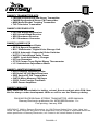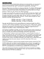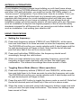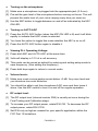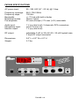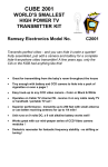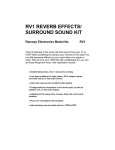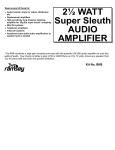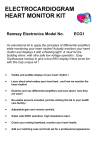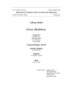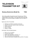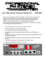
1
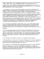
User Manual for Ramsey Model No. FM100B Here’s the ultimate radio transmitter for all of you home brew DJs out there! This all-in-one stereo transmitter has all the features you will ever need for transmitting a school radio station, around your yard, or even around the block. Use the optional high power configuration for extra boost when transmitting outside of the US! • 2 Line inputs and one mic input-plus a built in mixer! • New Line output for monitoring your show! • PLL Crystal controlled for rock solid frequency • Left and right channel peak hold indicators and large LED frequency display • Built in power supply, just plug it in! Now operates from 85-264VAC (47 - 63 Hz) without jumpers! • 25 mW output standard, optional 1W configuration for operation outside the US! • Auto AGC microphone muting function for cool talk-overs • Rugged steel enclosure for years of service (L) MIC ON +9 +6 +3 0 -3 -6 -9 -12 -15 -18 FREQ LOCK FREQUENCY POWER FREQ UP FREQ DOWN SETUP AUTO AGC MIC SELF TEST AUDIO LEVEL LINE 1 (R) +9 +6 +3 0 -3 -6 -9 -12 -15 -18 LINE 2 NA L S S IOE O E F P R O ST E R TER F M S M IT N TRA MIC MIC INPUT Model FM100B FM100B • 1 RAMSEY TRANSMITTER KITS • FM100B Professional FM Stereo Transmitter • FM25B Synthesized Stereo FM Transmitter • MR6 Model Rocket Tracking Transmitter • TV6 Television Transmitter RAMSEY RECEIVER KITS • FR1 FM Broadcast Receiver • AR1 Aircraft Band Receiver • SR2 Shortwave Receiver • SC1 Shortwave Converter RAMSEY HOBBY KITS • SG7 Personal Speed Radar • SS70A Speech Scrambler • BS1 “Bullshooter” Digital Voice Storage Unit • AVS10 Automatic Sequential Video Switcher • WCT20 Cable Wizard Cable Tracer • LABC1 Lead Acid Battery Charger • IG7 Ion Generator • CT255 Compu Temp Digital Binary Thermometer • LC1 Inductance-Capacitance Meter RAMSEY AMATEUR RADIO KITS • DDF1 Doppler Direction Finder • HR Series HF All Mode Receivers • QRP Series HF CW Transmitters • CW700 Micro Memory CW Keyer • CPO3 Code Practice Oscillator • QRP Power Amplifiers RAMSEY MINI-KITS Many other kits are available for hobby, school, Scouts and just plain FUN. New kits are always under development. Write or call for our free Ramsey catalog. FM100B PROFESSIONAL STEREO TRANSMITTER USER MANUAL Ramsey Electronics publication No. MFM100B Revision 1.1c First printing: January 2002 COPYRIGHT 2002 by Ramsey Electronics, Inc. 590 Fishers Station Drive, Victor, New York 14564. All rights reserved. No portion of this publication may be copied or duplicated without the written permission of Ramsey Electronics, Inc. Printed in the United States of America. FM100B • 2 Ramsey Publication No. MFM100B Price $10.00 USER MANUAL FOR FM100B PROFESSIONAL STEREO TRANSMITTER TABLE OF CONTENTS Introduction ......................................4 Using the FM100B ............................6 FCC Rules and Information ..............10 FM100B Specifications .....................19 Warranty ...........................................23 RAMSEY ELECTRONICS, INC. 590 Fishers Station Drive Victor, New York 14564 Phone (585) 924-4560 Fax (585) 924-4555 www.ramseykits.com FM100B • 3 INTRODUCTION TO THE FM100B First we will begin with a little history of stereo transmitters at Ramsey Electronics in order to give you an idea of how we arrived at the development of the FM100B as our latest stereo transmitter. We have many people call us each day asking questions about our earlier versions of transmitters such as the FM25B and the FM10A. Most are questions concerning drifting, sound quality, and transmitting distance. The tunable FM10A was a great product for a low-cost entry into the world of micro-power transmitters. The FM25B was the next step up offering a rock solid stable frequency just like professional stations. The latest step was to create a transmitter that not only has a rock solid frequency, but also all the features you would find in a commercial station. In answer to customer research and comments, here is the result of months of design and years of stereo transmitter experience. The FM100B has all of the features needed to run a professional sounding radio station. It includes extensive audio filtering to prevent high frequency audio interference, AGC (Automatic Gain Control) with the microphone to prevent overloading distortion, a frequency display with easy frequency adjustment, 2 line inputs, 1 microphone input, PLL controlled, CD quality transmission, and more. In other words we pulled all the stops to bring you a top quality product that will satisfy even the most discriminating user. Due to demand from our neighbors down south and wherever else it is legal, we have allowed for a special component section to be added to give you 1 watt of RF output. Simply install a few parts along with a good quality antenna and bingo, you’re on the air for miles around. We are happy to bring you this truly professional product that will give you many years of fun, reliable use, and enjoyment knowing that you have built it yourself. FM100B • 4 ADJUSTING YOUR FM100B TRANSMITTER: Keep all tests very brief until you have carefully chosen an open operating frequency in the FM broadcast band. 1. Transmitting Frequency: After finding a suitable "open" frequency in the 88-108 MHz FM band, adjust the frequency by first getting the FM100B into setup mode by pressing both FREQ keys at the same time. Then use FREQ UP and FREQ DOWN keys until you hear the carrier frequency on a nearby FM radio. No audio input is needed to make this first adjustment, you can simply listen for a "quieting" in the normal background noise "hiss." The modulation sensitivity of your FM100B will vary from one end of the broadcast band to the other, but not enough to worry about. This is explained by the characteristic curve of the varactor diode. In order to maintain the proper 75 KHz deviation, your front panel level control should be set so that the audio level meters read 0 with an occasional blink or two over that on the meter. The clipper circuit internal to the BH1415 will prevent over-modulation. 2. Audio Connection: Hooking up an audio source to your FM100B is really quite simple. However, there are some general rules: • A terribly distorted sound is a sign of too much audio level. Simply rotate the level potentiometers (R42 and R72) CCW to reduce the level. Make sure you rotate each one about the same amount to maintain proper stereo balance. • Stereo LP turntables are low-level output and will require the use of a preamplifier for proper audio input to the FM100B. • NEVER connect the FM100B audio inputs to speaker outputs of a high power stereo system; such a connection will destroy the IC chips. 3. Stereo balance: Due to the precise characteristics of the BH1415, we no longer need to adjust this. I left this here for the benefit of those boys (and girls) that are die-hard FM100 fans. FM100B • 5 USING THE FM100B WITHIN THE HOME: A most practical use for the FM100B would be to connect it to the main stereo system within a large home so that whatever is playing on the main system can also be tuned-in on portable FM radios in other rooms, the garage or in the yard. This connection consists of using shielded audio cables to connect the auxiliary "line audio" output of your cassette deck, CD player or other stereo device to the audio inputs of the FM100B. Consult the literature that came with your stereo equipment. Even if you intend use of the FM100B for your own home and family, it is still your responsibility (in accordance with Part 15 of the FCC Rules) to ensure that this operation does not cause interference to your neighbors. EXPERIMENTAL "BROADCASTING" PROJECTS: To use the FM100B successfully as a "broadcasting" service to interested listeners in a school or immediate neighborhood, most of your effort will be concentrated on smoothly "managing" or mixing the audio signals fed into the transmitter input. Operation of the transmitter itself consists of the following: 1. Correct construction and adjustment. 2. Carefully checking for an open frequency between 88-108 MHz in accordance with FCC Rules, Part 15. 3. Setting up a suitable antenna. 4. Connecting the audio source to the Left and Right RCA input jacks. 5. Turning on the transmitter while you intend to be "on the air" and turning it off when you are finished. 6. For extra protection, use the monitor out RCA jacks to either record your shows or listen to them on a stereo or on headphones. This will assure quality sound and transmission. You will need a headphone amplifier to boost the output of the FM100B to suitable headphone levels from the line level present at J6. FM100B • 6 ANTENNA IDEAS: Although use of the included whip antenna is recommended, you may want to use an external antenna to get a more uniform coverage. Use an external antenna mounted on the rear F connector to expand your coverage. Ramsey Electronics now offers an antenna called the “Tru-Match FM Broadcast Antenna”. This antenna has been specifically tested and designed for the FMseries of micropower transmitters and will help you get the most out of these products. When you call, ask for the TM100 antenna. A simple, yet very effective, antenna for the FM100B consists of a "dipole" (set up either horizontally or vertically) connected to the transmitter RF output jack through a few feet of coaxial cable (either RG-58, RG-59 or miniature RG-174, available at Radio Shack and other sources). Correct dipole lengths for major sections of the 88-108 MHz band are: 88 MHz, each side: 2.7 feet; 5.4 feet total 98 MHz, each side: 2.4 feet; 4.8 feet total 108 MHz, each side: 2.2 feet; 4.4 feet total You can see that there is not a great difference in antenna length from 88 to 108 MHz. Some antenna designers have the view that an "approximate" dipole such as 2.5 ft. on a side will do fine, while others believe it is worth the effort to calculate the length for your exact frequency, using the simple formula of Length (of one side, in feet) = 234/Frequency in MHz. If the dipole is installed vertically, the end connected to the center conductor of the coax should be the upper (higher) end. If young children will be around the set-up, a flexible wire antenna is preferable rather than rigid tubing. A "ground plane" antenna can be quite effective. A ground plane consists of one vertical element (the same length as one side of a dipole) connected to the center conductor of the coax. Four "radials" are connected to the shielded side of the coax at a 90 to 135 degree angle to the vertical element. The dipole formula is also used to calculate the length of the radial; since radials should be slightly longer than the main element, use 240 rather than 234 in your calculations. If you are equipped to make the field strength measurements required by Part 15 FCC rules, and you think it would be best to aim or "focus" your signal in a narrower direction, consult an antenna handbook and design a suitable gain antenna. See Appendix A concerning FCC field strength limitations. An FMVHF TV receiving antenna could be easily modified for such a purpose. Ham radio books and magazines are filled with antenna principles and ideas which can be adapted to your application. Also, you may wish to look at Radio Shack book No. 62-1083 on antennas. FM100B • 7 ANTENNA ALTERNATIVES: If your situation involves a single large building or multi-level home where reception from the FM100B antenna may tend to be uneven because of walls and other VHF path obstacles, you might set up the FM100B's output in a "carrier-current" configuration. If you know how, then do so safely. If not, you can show your FM100B and this book to a licensed radio engineer and negotiate with that person for a safe installation which will feed your signal through interior wiring of your home or building. Do not attempt such an installation unless you know exactly what to do (and what not to do). Because such an installation is beyond the original purpose of this kit and the safety standards intended for all Ramsey kits, we cannot provide further details for such an installation. Just wetting your whistle a bit! USING YOUR FM100B • Setting the frequency: [1] Press both frequency buttons (FREQ UP and FREQ DN ) at the same time and hold them in for three seconds to enter the frequency set mode. The FM100B will confirm your mode selection with 3 short beeps and the far right decimal point will begin to flash. Note that the far left decimal point will also flash if the unit is in stereo mode. [2] Press and hold either FREQ button; the frequency should scroll accordingly through the valid values. [3] When you have selected your new operating frequency, press both frequency buttons again and hold until you hear the triple beep confirmation. This means the settings have been saved in Flash. • Toggling Stereo Mode (Stereo / Mono operation): [1] Press both frequency buttons (FREQ UP and FREQ DN ) at the same time and hold them in for three seconds to enter the frequency set mode. The FM100B will confirm your mode selection with 3 short beeps and the far right decimal point will begin to flash. [2] Press the auto AGC button to toggle the stereo mode on and off. Note that the far left decimal point will flash only if the unit is in stereo mode. [3] When the mode is selected, press both frequency buttons again and hold until you hear the triple beep confirmation. This means the settings have been saved in Flash. FM100B • 8 • Turning on the microphone: [1] Make sure a microphone is plugged into the appropriate jack (3.5 mm). [2] Pre-set the gain level of the microphone before coming on the air. This will prevent the audio level of your voice varying every time you come on. [3] Use the MIC button to toggle between on and off as indicated by the MIC ON LED.. • Turning on AUTO AGC [1] Press the AUTO AGC button (when the MIC ON LED is lit) and it will blink rapidly to indicate that AGC mode is selected. [2] You have the option to toggle this mode whether the MIC is on or off. [3] Press the AUTO AGC button again to disable it. • Viewing PLL Operating Voltage: [1] Press both MIC and AUTO AGC at the same time. [2] Volts will display in 1/10 of a volt accuracy. [3] This mode can be saved as default by entering and exiting setup mode to save frequency. (See setting the frequency) [4] Press both keys again to return to normal mode. • Volume levels: [1] Make sure music source peaks remain below +3 dB. Any more level and you introduce too much distortion. [2] You should be able to set the microphone AGC once and then leave it alone. Use the MIC switch to turn it on and off for regular operation. • RF output level: [1] The RF output level (internal resistor R36) is usually set once during the Final Testing and Calibration stage. [2] To increase your RF output power, rotate R36 CW. To decrease the RF output power, rotate R36 CCW. [3] Set R36 only as high as needed for your specific application within the FCC Part 15 limitations. FM100B • 9 APPENDIX A: FCC RULES AND INFORMATION The Rules of the FCC (Federal Communications Commission) and your kit built FM Stereo Transmitter. An basic introduction of applicable FCC regulations. This basic introduction is just that: basic and introductory. A complete and thorough explanation of the FCC rules requires a reading of the regulations contained in the “Code of Federal Regulations, Part 15.” To order your copy of FCC rules part 15, call the US Government, Superintendent of Documents, at 202-512-3238, or fax at 202-512-2250. To order the correct document, ask for “CFR Title 17: Parts 1 to 19.” The cost is $30.00 or so, Master Card and Visa accepted. It is the policy of Ramsey Electronics, Inc., that knowing and observing the lawful use of all kits is a first responsibility of our kit user-builders. We do not endorse any unlawful use of any of our kits, and we do try to give you as much common sense help about normal and lawful use as we can. Further, it is the policy of Ramsey Electronics, Inc., to cooperate with all applicable federal regulations in the design and marketing of our electronics kit products. Finally, we urge all of our overseas customers to observe the regulations of their own national telecommunications authorities. In all instances, compliance with FCC rules in the operation of what the FCC terms an "intentional radiator" is always the responsibility of the user of such an "intentional radiator". In the United States, this is how the FCC regards your transmitter kit: Licensed FM broadcast stations and their listeners have ALL the rights! Your use of a device such as the FM100B kit MAY have some limited privileges in locally-unused band space. Unlicensed operation of small transmitting devices is discussed in "Part 15" of the FCC Rules. These Rules are published in 100 "Parts," covering everything imaginable concerning the topic of "Telecommunications." The six books containing the FCC Rules are section 47 of the complete Code of Federal Regulations, which you are likely to find in the Reference section of your Public Library. If you have questions about the legal operation of your FM-100 or any other kit or home-built device which emits RF energy, it is your responsibility to study the FCC regulations. It is best if YOU read (and consult with a lawyer if you are in doubt) the rules and do not bother the understaffed and busy FCC employees with questions that are clearly answered in the rules. FM100B • 10 Here are the primary "dos and don'ts" picked from the current FCC Rules, as of May, 1990. This is only a brief look at the rules and should not be construed to be the absolute complete legal interpretation! It is up to you to operate within the proper FCC rules and Ramsey Electronics, Inc. cannot be held responsible for any violation thereof. 1. In the past, no "two-way communications" use of the 88-108 MHz FM broadcast band was permitted. This prohibition does not appear in the current edition of Part 15. Previous editions of Part 15 discussed "wireless microphones" (such as Ramsey FM1, FM4, etc.), while the June 23, 1989, revision eliminates this discussion in favor of more detail regarding computer and TV peripherals and other modern electronic conveniences. However, it is not immediately clear that the 1989 revision of the FCC Rules Part 15 necessarily "cancels" previous regulations. Laws and rules tend to remain in force unless they are specifically repealed. Also, FCC Rule 15.37 discusses "Transitional Provisions for Compliance with the Rules," and states in item (c): "There are no restrictions on the operation or marketing of equipment complying with the regulations in effect prior to June 23, 1989." 2. It is the sole responsibility of the builder-user of any FM broadcast-band device to research and fully avoid any and all interference to licensed FM broadcast transmission and reception. This instruction manual gives you practical advice on how to do a good job of finding a clear frequency, if one is available. 3. For some frequency bands, the FCC sets 100 milliwatts (0.1 watt) as the maximum permitted power output for unlicensed, home-built transmitting devices, and that the combined length of your antenna and feedline (coaxial cable or other) must not exceed 10 feet. The technical standards for 88-108 MHz are very different, primarily concerned with band width and RF field strength. 4. FCC Rules do not differ for "stereo" or "monaural" transmissions. 5. Broadcasting on the grounds of a school (AM emissions only) is specifically permitted and encouraged between 525 and 1705 KHz under Part 15.221. Use our AM1 AM radio broadcast kit for this use. 6. FCC Rule No. 15.239 specifically addresses operation in the 88-108 MHz FM broadcast band for which your FM100B transmitter kit is designed. However, this Rule does not, by itself, tell you everything you need to know about using a device of this kind. Therefore, we are noting a series of Part 15 regulations which should be observed: FM100B • 11 a. The transmitter must NEVER be tuned to a frequency above 108 MHz, specifically the band 108-121.94 MHz, FCC Rule 15.205 lists this band as restricted, due to potential interference with aircraft navigation equipment. b. The "bandwidth" of your transmission is limited to 200 KHz, centered on the actual operating frequency. Since 200 KHz is enough spectrum space for several different FM stations, this is a "generous" limitation designed to accommodate cruder FM devices. Properly built and adjusted, the FM100B kit operates well within this limit. In fact, its signal should sound no "wider" than any other FM station when listening on an ordinary FM radio. c. FCC Rule 15.215(a) says: "Unless otherwise stated, there are no restrictions as to the types of operations permitted under these sections." This general provision appears to leave you free to use your FM stereo transmitter in a manner similar to operations of an FM broadcasting station, or to use it for any other non-interfering, practical application. d. FCC Rule 15.5: General conditions of operation: "(b) Operation...is subject to the conditions that no harmful interference is caused and that interference must be accepted that may be caused by the operation of an authorized radio station, by another intentional or unintentional radiator, by industrial, scientific and medical equipment, or by an incidental radiator. (c) The operator of a radio frequency device shall be required to cease operating the device upon notification by a Commission representative that the device is causing harmful interference." e. The most specific FCC regulation of 88-108 MHz FM Broadcast band unlicensed operation is that the "field strength" of the signal must not exceed 250 microvolts/meter at a distance of 3 meters from the transmitter (FCC rule 15.239). If you have any concern about this emission limit, have your device checked by a technician with accurate measuring equipment. Remember that the "field strength" of a signal is determined as much by the antenna as by the RF output of the transmitter itself. FM100B • 12 DISTANCE FROM TRANSMITTER ANTENNA METERS FEET FIELD STRENGTH (µV) TOTAL RECEPTION AREA 3 10 250 314 FT 6 20 125 1256 FT 12 39 63 4800 FT 24 78 31 19113 FT 48 157 15 1.8 ACRES 96 315 7.5 7.2 ACRES 192 630 3.8 28.6 ACRES 384 1260 1.9 11.4 ACRES 768 2520 .95 458 ACRES 1536 5036 .5 1830 ACRES APPENDIX B: UNDERSTANDING LEGAL "FIELD STRENGTH" A "microvolt" is one-millionth of one volt and designated "µV" in the following explanations. The new FCC Part 15 Rules specify a maximum "Field Strength" of your transmitted signal. Since it is unlikely that you have the equipment to carry out accurate field strength measurements in microvolts, it is useful to understand at least the theory of field strength so that you can understand both what you can expect from such transmitters, and what limits the FCC intends. Previous limits on non-licensed FM-broadcast band devices were defined as a maximum field strength of 40µV per meter measured at a distance of 15 meters. The June 1989 revised rule specifies a maximum of 250 µV per meter, but measured at 3 meters from your antenna. Both limitations are the same in practice. "250µV per meter" means that an accurate field-strength meter with a 1-meter antenna may indicate a maximum signal field strength of 250µV (In contrast, non-licensed operation from 26.96 to 27.28 MHz is limited to a field strength of 10,000 µV per meter at 3 meters). FM100B • 13 In all cases, the field strength of a signal decreases in direct proportion to the distance away from the antenna. Power decreases by the square of distance: for every doubling in distance, the signal power is quartered, but the field strength voltage is only halved. Using this theory, we can construct a simple chart to show the maximum permitted performance of a non-licensed FM band transmitter. The theoretical figures assume a simple 1 meter receiving antenna in all cases and do not take into consideration that reception can be greatly enhanced with larger, multi-element antennas and preamplifiers. In the following chart, the field strength (theoretical minimum) gets even stronger as you move from the edge of these circular boundaries toward the antenna: This "exercise in meters and microvolts" demonstrates that the FCC clearly intends to limit the theoretical range of non-licensed devices operating in this band. It also shows the potential for causing interference at a home down the street from you. But it also shows that you can legally put out quite a good signal over wider areas than you might have imagined. For other kinds of radio services, the FCC restricts such factors as transmitter power or antenna height, which cannot really limit the possible "range" of a transmission under good conditions. By restricting the maximum field strength at a specific distance from your antenna, the FCC clearly plans for your signal to "die out" at a specific distance from your antenna, no matter what kind of transmitter power or extra-gain antenna you are using. On the other hand, the FCC standards do make it legal and possible for you to broadcast on a school campus, campground or local neighborhood, as long as you do not cause interference to broadcast reception. “Why talk about acres"? There are three reasons to translate our look at "field strength" into "acres". (1) The first one is easy: the numbers would get too cumbersome if we discussed your possible signal coverage in terms of square feet or square meters. (2) It's very easy to see that your signal can easily and legally serve a school campus or wilderness campground. (3) And, if we remember that typical urban single-family home sites run from 1/4 to 1/2 acre on the average, it should become extremely clear that your obligation to avoid interfering with broadcast reception can easily involve hundreds of homes, before adding apartments! In fact, the most significant distance in the above chart is the 1.9 µV signal strength permissible at 1260 feet (about 1/4 mile), covering a circular area of FM100B • 14 about 114 acres. A quick glance at stereo FM receiver specifications shows typical sensitivity of 1.7 µV before considering high-gain antennas or preamplifiers. Your non-licensed signal can provide serious competition to a public broadcast station fifty miles away, a station which someone in your neighborhood may have set up a special antenna to enjoy. Calibrated "field strength meters" such as described in the ARRL Radio Amateur's Handbook can detect signals down to about 100 microvolts. To measure RF field strength below such a level, professional or laboratory equipment and sensitive receivers are required. A "sensitive" receiver responds to a signal of 1 or even .5 microvolt "delivered" to the receiver input by antenna. If the antenna is not good, the receiver cannot respond to the presence of fractions of a microvolt of RF energy. FM100B • 15 SUMMARY The present edition of Part 15 of the FCC rules does not provide detailed guidance on ALL aspects of using a low-power transmitter such as the FM100B. The main point is that you may not cause any interference whatsoever to licensed broadcast services and that you must be willing to put up with any interference that you may experience. Lawful use suggestions for the FM100B 1. Build and adjust this kit strictly according to the published instructions. 2. Use the whip antenna supplied. 3. Do not modify your kit in any way. 4. Check your intended operating frequency very carefully, as clearly explained in this instruction manual, to ensure you will not cause interference to reception of licensed broadcasting. 5. If you receive ANY complaint about your transmissions interfering with broadcast reception, stop or change your operation IMMEDIATELY. 6. If you are contacted by the FCC regarding use of this device, cooperate fully and promptly. 7. Do your own homework and research to understand and comply with present and future FCC rulings concerning devices of this kind. 8. Do not use made-up "station call signs" to identify your transmissions. Only the FCC has the authority to issue such callsigns. Use some other way to identify your transmitting activity, such as "This is Stereo 90.5, Seabreeze School Student Music Radio," and so forth. 9. Identify the location and purpose of your transmissions from time to time. This is common courtesy toward other persons who may hear your signal. The FCC is toughest about clandestine transmissions which cost time and money to track down. 10. Do not assume that the mere fact that you purchased this kit gives you any specific right to use it for any purpose beyond generating a low-level RF signal which is barely detectable beyond the perimeter of your personal dwelling space. Finally, the FCC Rules call for the posting of printed notices on devices FM100B • 16 intended for non-licensed operation under Part 15 Rules. You will find such notices written up for the front or back of the instruction manual for nearly any computer or video accessory that you have seen in recent months. Consult the Part 15 Rules for the exact wording of such notices. Following is a text for such a notice which responds to FCC rule making intentions: NOTICE: The radio-frequency "intentional radiator" device which may be constructed from kit parts supplied by us is intended and designed by Ramsey Electronics, Inc. to conform to applicable provisions of Part 15 of FCC Rules. The individual kit-builder and all users of this device assume responsibility for lawful uses conforming to FCC Part 15 Rules. Operation is subject to the following two conditions: [1] This device may not cause harmful interference, and [2] this device must accept any interference received, including interference that may cause undesired operation. FM100B • 17 Final comment A well-informed person will see today's FCC Rules to be evolving and progressively less-restrictive. Even though today's technology is far more complex than what was possible at the time of the Communications Act of 1934, the FCC rules are becoming more relaxed, giving radio experimenters more and more opportunities to explore many frequency bands, using many communications modes, with no need for a formal license of any kind. A thorough study of Part 15 of the FCC Rules, which is completely beyond the purpose of this kit manual, will show you many legal uses of radio transmitting devices which do not require licensing, either amateur or commercial. To provide more personal and club radio-learning opportunities, and to cut down on administrative costs, today's FCC permits far more non-licensed activity than at any time in previous history. On the other hand, today's FCC enforcement actions get bigger fines and real prison terms for scofflaws! From CB (now 3 bands of it, for varying applications) to easy entry-level Amateur Radio with long-term licensing, to numerous unlicensed Part 15 operations, the FCC is beginning to look out for the interest and good plans and intentions of private citizens and school-community groups as never before in radio communications history. Learn the rules...observe them...and have fun in radio! If you enjoyed this Ramsey product, there are plenty more to choose from in our catalog - write or call today! Or visit us on the web at: www.ramseykits. com! FM100B • 18 FM100B SPECIFICATIONS AC power input: 85 - 264 VAC (47 - 63 Hz) @ 1 Amp Frequency coverage: Frequency steps: Bandwidth: Broadcast modes: Pre-emphasis: 88.0 -108.0 MHz 100 kHz +/- 75 kHz with built-in limiter Stereo / Mono 50 usec (Europe) / 75 usec (U.S.) selectable Audio input: Microphone input: Monitor output: 1 V p-p (line level), 2 channels, RCA connectors mono 3.5 mm mic 1 V p-p (line level) RF output: adjustable 5 uW to 25 mW (20 - 25 mW typical) max, F style RF output connector Dimensions: Weight: 9.5” L x 6.0” W x 4.0” H 3.7 lbs. (L) MIC ON +9 +6 +3 0 -3 -6 -9 -12 -15 -18 FREQ LOCK FREQUENCY POWER FREQ UP FREQ DOWN SETUP AUTO AGC MIC AUDIO LEVEL LINE 1 SELF TEST (R) +9 +6 +3 0 -3 -6 -9 -12 -15 -18 LINE 2 NA L S S IOE O E F P R OM S T E R T E R IT F NSM TRA MIC MIC INPUT Model FM100B FM100B • 19 FM100B • 20 FM100B • 21 FM100B • 22 WARRANTY INFORMATION FACTORY ASSEMBLED UNITS This warranty applies to original purchasers only. All factory assembled products are warranted to be free from defects in parts or workmanship for a period of 1 year from the date of purchase. Proof of purchase must accompany the unit. This warranty applies to units that have not been modified, misused, abused or repaired by unauthorized personnel. Repairs are to be accompanied by payment of the basic repair fee of twenty dollars ($50.00). If the repair is deemed to be under warranty, you will not be charged. Repair will be delayed waiting for proper payment receipt. You will be notified of any additional costs for repair. A description of the problem and legible return address are required to be returned along with the unit. Time involved for repair depends on the product. It typically runs one to two weeks after factory receipt. Ramsey Electronics reserves the right to refuse repair on any item. REFUNDS: You are given ten (10) days to examine our products. If you are not satisfied, you may return the product in original condition including instruction and proof of purchase to the factory for a full refund. The return package should be packed securely. Insurance is recommended. Ramsey Electronics,Inc. 590 Fishers Station Drive Victor, NY 14564 Phone (585) 924-4560 Fax (585) 924-4555 FM100B • 23 PROFESSIONAL FM STEREO TRANSMITTER KIT Quick Reference Guide Introduction ..................................... 4 Using the FM100B ........................... 6 FCC Rules and Information ............. 10 Specifications ................................... 19 Warranty .......................................... 23 Price: $10.00 Ramsey Publication No. MFM100B Assembly and Instruction manual for: RAMSEY MODEL NO. FM100B RAMSEY ELECTRONICS, INC. 590 Fishers Station Drive Victor, New York 14564 Phone (585) 924-4560 Fax (585) 924-4555 www.ramseykits.com FM100B • 24