1
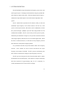
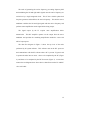
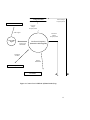
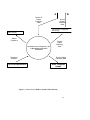
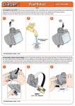
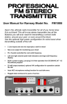
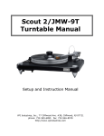
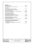
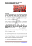
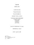
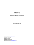
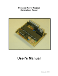
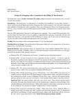
West Virginia University
College of Engineering
Department of Computer Science and Electrical Engineering
EE/CpE 180 Senior Design
Spring 2001
@Home Radio
FINAL PROPOSAL
Team #17
Michael Guinn
Christopher Johns
Travis Masoner
Perry Minigh
Proposed Budget: $64.50
Faculty Monitor
Dr. Wils Cooley
Sponsor
Dr. Mathew Valenti
Date
April 23, 2001
Contact Person:
Michael Guinn
202 Wagner Road
Morgantown, WV 26501
(304) 216-0721
[email protected]
TABLE OF CONTENTS
1.
2.
INTRODUCTION ............................................................................................................3
DESIGN OBJECTIVES...................................................................................................5
2.1 DESIGN GOALS AND CONSTRAINTS ....................................................................................5
2.2 DESIGN SPECIFICATIONS .....................................................................................................7
Performance.......................................................................................................................7
PC Interface.......................................................................................................................7
Signal Source .....................................................................................................................7
Software.............................................................................................................................8
Power ................................................................................................................................8
Size and Weight ..................................................................................................................8
2.3 DELIVERABLES ..................................................................................................................8
2.4 VALIDATION ......................................................................................................................9
3.
SYSTEM DESCRIPTION..............................................................................................11
4.
ORGANIZATION AND PLANNING............................................................................17
5.
QUALIFICATIONS.......................................................................................................20
6.
REFERENCES...............................................................................................................24
7.
APPENDIX.....................................................................................................................25
2
1. INTRODUCTION
The lifestyles of people frequently change due to technological advances
targeted at making life better, easier, and more efficient. A large amount of new
technology is directed towards the workplace, but people also create a demand for
products that provide leisure and relaxation. The development of MP3
technology and the widespread use of the personal computer as a multimedia
entertainment device has created the desire to conveniently capture the capability
and versatility of the PC on existing audio equipment.
The radio emerged as a form of family entertainment in the early 20 th
century and remains a principal source of entertainment today. Many devices
such as alarm clocks, automobiles, stereos, and CD players incorporate FM
receivers. The simplicity and abundance of FM receivers makes it desirable to
create new devices that exploit FM transmission technology so that it can be
customized for individual use.
Since the introduction of the MP3 audio format, many people have created
immense libraries of music stored centrally on their PC hard drives. The sound
quality of low-end speakers and the limited power output from a computer sound
card, typical of most PCs in use today, leaves many users dissatisfied with their
current setup. Present solutions currently exist, but not without limitations and
other drawbacks.
Connecting a PC to existing stereo equipment that has the desired
performance qualities solves the problem, but has limitations. This approach
requires arranging a room to accommodate both the stereo and PC equipment or
3
running wire between rooms to connect the devices. These limitations are
inconvenient and limit the area where the music can be heard.
Another solution requires the purchase of a high-end PC speaker and an
amplification system. This method also limits the listening area, and requires
investment in additional sound equipment. This system must be installed and
setup, and leaves adequate existing equipment idle.
By purchasing an audio transmission/reception product, the problem can
be solved, but limitations remain. Here, because commercially available products
operate at frequencies outside the standard FM bandwidth, a transmitter and
receiver pair is required. This method remains deficient when it is desired to
listen to music on more than one piece of audio equipment simultaneously.
Multiple receivers would be required which increases the cost of the solution.
Also, many types of audio equipment that have FM receivers built in, do not have
auxiliary audio input jacks, which makes them incompatible with the receiver
modules.
All of the previously mentioned solutions require physical connection to
both the sound source and the sound producing components. These connections
produce limitations in the effectiveness of the system, and involve additional
expenses or complicated setup. Users want to listen to their music in the locations
they desire without the annoyance of connecting wires, and they want to be able
to do this without replacing the equipment they already have. They need a means
to accomplish these goals that provides versatility and remains cost effective.
4
2. DESIGN OBJECTIVES
2.1 Design Goals And Constraints
The @Home Radio is a FM transmission system that will broadcast the
desired input audio signal such that it can be tuned in with any existing standard
FM receiver. It will operate in the frequency range of 88 to 108 MHz, and be
powered by a 120V AC, 60Hz source or a 12V, DC source. This versatility
permits operation from a wall outlet in the home as well as a cigarette lighter in an
automobile.
The @Home Radio will be capable of broadcasting a stereo FM signal,
and will accept two audio inputs, a left and right channel. These inputs must be
compatible with standard RCA jacks.
The output frequency of the product may be controlled with or without the
presence of a personal computer. When a PC is not present, the frequency will be
able to be selected and modified with manual controls located on the product
itself. The selected frequency will be displayed on the device, and there will be a
control for switching between PC and manual control.
When the @Home Radio is connected to a computer, the supplied
software will control the frequency of operation. This software will run on a
Windows platform, and have a graphical user interface. It will allow the selection
of the transmission frequency, and display the frequency that was selected.
The @Home Radio will be easy to use. Software installation will be
straightforward and user friendly, with easily accessible help files to supplement
5
the functional program. Sufficient documentation describing how to use the
product will be included and will be in the form of a user’s manual.
Figure 1 illustrates how a user might implement the @Home Radio.
Figure 1. User implementation of the @Home Radio
The @Home Radio requires three essential items for correct operation: a
power supply, signal source, and an FM receiver. To power the @Home Radio
the user must connect it to a home wall outlet using the supplied AC adapter, or to
a cigarette lighter with the supplied cigarette lighter adapter. Also, the desired
audio source must be connected to the RCA jacks to supply the signal to be
transmitted. Once the unit is powered, turned on, and the audio source is
providing a signal, the user can tune in the transmitted signal on their FM
receiver.
For manual adjustment of the frequency the user may adjust the controls
located on the device to change the frequency. When this occurs, the @Home
Radio changes the transmission frequency, and the frequency display on the
device is updated. The user will then need to retune the FM receiver such that it
corresponds to the transmission frequency.
6
The @Home Radio also provides a means for PC controlled operation,
and this requires some added setup. The user must install the software supplied
with the @Home Radio, and the device must be connected to the computer with
the included cable. The software will be straightforward and take very little time
to learn. The user must run the @Home Radio program that was installed, and,
provided that the previous steps for operating the @Home Radio have been
completed, the user can change the transmission frequency via the mouse and/or
keyboard. The @Home Radio will respond to the frequency change the same as it
does when it comes from the manual controls. Also, the user will again need to
retune the FM receiver to match the selected transmission frequency.
2.2 Design Specifications
Performance
? Output a stereo FM signal
? See Appendix A for Audio Quality Specifications
? Output frequency ranging from 88–108 MHz with 200 kHz increments
(See Appendix A)
? Output power of 100 mW (See Appendix A)
PC Interface
? Standard 9-pin serial connector
? Serial port voltage levels of -3–25 V
? Serial port maximum current of 500 mA
Signal Source
? Connects via standard RCA jacks
7
? Max audio input level of –10 dBV (See Appendix A)
? Audio input frequency band of 20 Hz – 15 kHz (See Appendix A)
Software
? Operates on a Windows operating system
? Employs a graphical user interface
? Will have Graphical User Interface
? Will be compatible with audio playback software such as Winamp or
Real Player
Power
? 120 V AC or 12 V DC
Size and Weight
? Maximum dimensions of 10" x 6" x 4"
? Maximum weight of 2 lbs.
2.3 Deliverables
? @Home Radio unit
? 120 VAC to 12 VDC adapter
? Cigarette lighter adapter
? Serial cable
? Software CD
? User Manual
? Service Manual
8
2.4 Validation
A testing environment will be set up upon completion of the device. A
sequence of acceptance tests will be performed to validate its compliance with the
initial requirements of the device. The following procedure must be followed to
begin testing.
? Connect the device using the AC adapter to a wall outlet or the
cigarette lighter adapter to a cigarette lighter.
? Connect the audio source to the RCA jacks on the device
? For PC control testing connect the PC to the device with the serial 9
pin serial cable, turn on the PC and load the @Home Radio software
The system will be tested both with and without a PC connection. Table 1
details the tests to be performed and the acceptable results.
9
Table 1. Acceptance Testing Procedure and Expected Results
Performance Test
Transmission of audio
signal
Transmission of stereo
signal
Transmission frequency
ranges from 88-108 MHz
with 200 kHz increments
100 mW Output Power
Produced
Testing Method
Transmission frequency is
selected and tuned in on
FM receiver
Three separate tests will be
conducted: one with signal
sent to the left-channel
only, one with signal sent to
the right-channel only, and
one with signal sent to both
channels
The transmission frequency
is set to each value from 88108 kHz with 200 kHz
increments and the FM
receiver is tuned to the
corresponding frequency
Measure output voltage and
current levels with
multimeter
Manual controls function
The frequency is selected
with manual control and the
FM receiver is tuned to the
new frequency
PC controls function
The frequency is selected
with the PC program and
the FM receiver is tuned to
the selected frequency
Acceptance
Criteria
The signal is received and
heard
The left and right signals
can be heard in the
corresponding left and right
speakers of the receiving
system
The signal can be heard at
each transmitted frequency
when tuned to the same
frequency
Output Power = 100 mW
The signal is heard on the
FM receiver and the
frequency display on the
device is updated— If PC is
connected the display is
updated on the monitor
The signal is heard on the
FM receiver and the new
frequency is displayed on
both the PC and the device
10
3. SYSTEM DESCRIPTION
The @Home Radio accepts the transmission frequency, power source, and
audio signal as inputs. The display of the transmission frequency and the FM
audio signal are outputs of the system. The block diagram shown in Figure 2
outlines these inputs and outputs as well as the internal components of the
system.
The PC control block represents the PC software’s ability to select the
transmitted output frequency. The software interacts with the user of the
system via the keyboard, mouse, and monitor, and it communicates with the
PIC processor through a standard 9-pin serial cable using the RS-232 serial
communication standard. The PC is not necessary for the system to operate,
illustrated by the dotted line in Figure 2, but it provides convenient selection
of the output frequency and allows the user to broadcast digital audio. When
the device is connected to the PC, it will be able to accept frequency selection
from both the PC and Up/Down frequency buttons.
Two push button switches will provide manual control of the frequency
selection.
These switches are used to increase and decrease the output
frequency in increments of 200 kHz. The PIC processor continuously polls
these switches to determine if a change in output frequency is necessary.
The PIC processor interprets the values from the manual and PC controls
and determines the selected frequency. This frequency is output to the display
driver that controls the 7-segment display, and, if a PC is connected, it is
serially transmitted to the PC for the software to display.
11
The tasks of generating the carrier frequency, preventing frequency drift
and modulating the left and right audio signals onto the carrier frequency are
carried out by a single integrated circuit. This IC has a built-in phase-lock
loop that generates and stabilizes the carrier frequency. This built-in stereo
modulator combines the left and right signals with the carrier frequency and
performs some amplification on the signal before being output.
The signal output by the IC requires more amplification before
transmission.
This RF amplifier operates on the output from the stereo
modulator and provides the remaining amplification needed to source 100
mW of output power.
The data flow diagram in Figure 3 shows the top level of the tasks
performed by all system software. This software runs on the PIC processor
and communicates with the PC software when a PC is present. Figures 4 and
5 separate the tasks into two areas – those to be completed by the PC (Figure
4), and those to be completed by the PIC Processor (Figure 5). Arrows that
connect the two diagrams show where data is shared between the PC and PIC
via a serial cable.
12
Block Diagram
FM Transmitter
7-Segment Display/
PC Monitor
Audio Signal
Display
Information
Output
Frequency
@Home Radio
Software
Commands
and Data
Frequency
Selection
PC Keyboard / Mouse
Up/Down Push Buttons
Figure 3. Context Level 0 DFD for @Home Radio
Configuration Data
Current Output
Frequency Data
FM Transmitter
Previous
Output
Frequency Data
Audio Signal
Current PC
Output
Frequency Data
Send Audio
Signal
Audio Signal
Information
Get User’s Frequency
(Interactive PC Program)
Commands
and Data
Display
Information
PC Keyboard
PC Monitor
A
B
Figure 4. Context Level 1 DFD for @Home Radio (Top)
15
A
B
Current PC
Output
Frequency
Data
Current
Output
Frequency
Data
PIC Frequency Configuration
Data Storage
FM Transmitter
Output
Frequency
Determine Correct Frequency (PC
or Board DIP) and Send to
Transmitter
Frequency
Selection
Current
Output
Frequency
Data
Current Output
Frequency Data
Up/Down Push Buttons
Board 7-Segment
Display
Figure 5. Context Level 1 DFD for @Home Radio (Bottom)
16
4. ORGANIZATION AND PLANNING
Table 2, shown on the following page, is a Gantt Chart that displays a
proposed schedule for design implementation. To be completed in the Fall
2001 semester, this chart shows which tasks are to be completed, the week-byweek schedule for completion of each task, and the group members
responsible for completing each task. A bold number in the personal effort
column indicates the group member who is ultimately responsible for each
task.
17
BUDGET
Table 3. Proposed Budget
1. PIC Processor
2. RS-232 Converter
3. Stereo Modulator
4. RCA Jacks
5. Power Adapter
6. Antenna
7. RF Amplification Components
8. Frequency Display
9. Packaging
10. Oscillators
11. Miscellaneous Items
Total Cost
$11.00
$4.00
$5.00
$1.50
$8.00
$8.00
$10.00
$4.00
$5.00
$6.00
$2.00
$64.50
Total Requested from CSEE Senior Project Account: $64.50
_________________________________________
Project Sponsor Signature
Date
_________________________________________
Project Monitor Signature
Date
18
Table 4. Budget Justification
1. PIC Processor
PIC16F877
Newark #12C1952
2. RS-232 Converter
MAX-232: 5V, Multi-Channel RS-232 TX/ RX
Digikey #MAX232CPE-ND
3. Stereo Modulator
BH1415
Rohm #BH1415
4. RCA Jacks
2 RCA style jacks @ $0.65 each
Jameco #112475
5. Power Adapter
120 VAC to 12 VDC
Jameco #104578
6. Antenna
1/4 wave whip antenna and connector
Digikey #ANT-315-PW-LP-ND
and #CONREVSMA002-ND
7. RF Amplification Components
1/4 W resistors, capacitors, transistors
8. Frequency Display
4 7-segment displays @ $1.00 each
Jameco Electronics #161517
9. Packaging
1/8" Plexiglass sheet
Lowes
10. Oscillators
2 Crystal Oscillators
Digikey
11. Miscellaneous
Solder, Glue
Lowe's
19
5. QUALIFICATIONS
Resumes for the designers of the @Home Radio System – the FM Audio
Link Gold Team – are provided on the following four pages.
20
202 Wagner Road
Morgantown WV 26501
Phone (304) 216-0721
E-mail [email protected]
Michael R. Guinn
Objective
Employment
To further my knowledge and experience in the areas of computers and
electronics through coursework and job-related experience.
May 2000 – Present
West Virginia University
Morgantown, WV
Networking Assistant for College of Engineering
? Maintained phone and network connectivity
? Installed numerous fiber optic and CAT-5 cables in a network upgrade
? Assisted in SRX phone system installation
July 1995 – May 2000 McDonald’s of Weston
Crew Trainer
Weston, WV
? Trained new crew members in customer service and cooking
procedures
? Operated cash registers and food preparation equipment
? Cleaned equipment, transferred products to neighboring stores
Education
1997 – Present
West Virginia University
Morgantown, WV
BS Computer Engineering, BS Electrical Engineering
?
?
?
?
Expected Date of Graduation: December 2001
GPA: 3.36 / 4.00
Presidential Scholarship, National Merit Scholarship
Dean’s List 3 Semesters
Qualifications
Operating Systems:
? MS Windows 3.1, 95, 98, ME, NT, 2000; Unix; OS/2
Programming Languages:
? Ada, ANSI C, Assembly, Basic, HTML
Networking:
? 4-pair and 25-pair cable termination; Single, 6, and 24 jack panel wiring;
Fiber optic wire termination; Cisco switch web browser-based operation
Software:
? MS Word, Excel, PowerPoint; MATLAB; Various Browsers & Mail
Programs
References
Provided upon request.
21
PO Box 528
Jane Lew, WV 26378
Phone (304) 884-7738
E-mail: [email protected]
Perry L. Minigh
Objective
A computer or electrical engineering position where my education and skills will
be fully utilized and my potential enhanced while enabling me to make a
contribution.
Education
August 1997 – Present
West Virginia University
Expected Degrees in December 2001
?
Bachelor of Science in Computer Engineering.
?
Bachelor of Science in Electrical Engineering.
Morgantown, WV
Area of Emphasis
?
Communications and Signal Processing.
Cumulative GPA as of May 2000
?
3.208 / 4.000
Technical
Skills
Working knowledge with C, Ada, Assembly Language, Unix, HTML, Matlab
including signal processing toolboxes, Pspice circuit simulation software,
Windows 95/98/NT, Microsoft Word, Excel, PowerPoint, and Publisher.
Work
Experience
J.W. Ebert Corporation (McDonald’s)
Crew Trainer
April 1996 – Present
Weston, WV
?
Pays approximately 30% of Cost of Education.
?
Responsible for training new employees job tasks and proper procedures.
?
Responsible for maintaining proper food production levels.
?
Responsible for maintaining / cleaning of equipment.
?
Cashier/Customer Service, created a friendly environment in all situations.
West Virginia Department of Highways
Summer Employee
Weston, WV
Summers 1998, 1999, & 2000
?
Leadership role over other summer employees.
?
Given various individual tasks and was responsible for their completion.
?
Various road construction activities such as hand patching paved roads,
replacing/installing minor drainage structures.
?
Provided support to the public during various duties such as flood clean up.
Professional
Memberships
Student Member of IEEE, IEEE Computer Society, IEEE Industrial Electronics
Society.
References
Provided upon Request
22
Travis Masoner
Rt. 1 Box 112M
Jane Lew, WV 26378
Home (304) 884-7525
School (304) 598-3186
[email protected]
Objective
To gain experience in the field of Computer and Electrical Engineering,
for further employment upon graduation.
Experience
1995–Present
Well Tender
Petroleum Resources Inc.
Roanoke, WV
? Maintain wells by weekly checks and repairs.
? Calculate average production weekly and monthly.
Summers 1998–1999
Labor Worker
Petroleum Resources Inc.
Roanoke, WV
? Painted and repaired wells that were in need.
? Constructed new office which included masonry, wiring, and carpentry.
Summers 1997–1998
Labor Worker
Kimberly Industries Inc.
Charleston, WV
? Worked with dirt compaction material and drainage materials.
? Operated miscellaneous equipment and also worked as a flagman.
Summers 2000
Intern
Information Research Corp.
Fairmont, WV
? Worked with software and system engineering resources
? Projects dealing with oracle and web base systems
? Created and maintained web pages.
Education
1997–present
West Virginia University
Morgantown, WV
BS in Computer and Electrical Engineering (expected, Dec.2001)
Departmental GPA: 3.1
Comment:
? IEEE member (Industrial Electronics and Computer Societies)
? Member of the Formula Lightning Team (electric racing project)
1996-1997
West Virginia Wesleyan College
High School Partnership in Education
? Completed two years of calculus
Buchannon, WV
Community
Activities
Member of the Boy Scouts of America as an Assistant Scoutmaster
(obtained the Eagle Scout Award as a youth).
References
Available upon request
23
6. REFERENCES
?
Web Page: “Digi-Key Corporation”
http://www.digikey.com/
?
Web Page: “Jameco Electronics”
http://www.jameco.com/
?
Web Page: “Newark Electronics”
http://www.newark.com/
?
Web Page: “Microchip Technology”
http://www.microchip.com/
?
Web Page: “ROHM Company, Ltd.”
http://www.rohm.com/
24
7. APPENDIX
This appendix contains excerpts from data sheets for the BH1415F and
MAX232 chips intended for use with the proposed @Home Radio system.
25