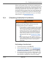
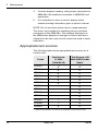
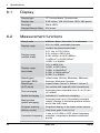
1
NBM-580 Narda Broadband Radiation Meter Operating Manual USA 435 Moreland Road Hauppauge, NY 11788, USA Phone: +1 631 231-1700 Fax: +1 631 231-1711 E-Mail: [email protected] www.narda-sts.us Germany Sandwiesenstrasse 7 72793 Pfullingen, Germany Phone: +49 7121 97 32-0 Fax: +49 7121 97 32-790 E-Mail: [email protected] www.narda-sts.com Italy Via Leonardo da Vinci, 21/23 20090 Segrate (MI) ITALY Phone: +39 02 26952421 Fax: +39 02 26952406 E-Mail: [email protected] www.narda-sts.it Contents 1 Useful information��������������������������������������������������������������������������������� 5 1.1 Measuring electromagnetic fields�������������������������������������������������������� 6 1.2 About this instrument � ������������������������������������������������������������������������ 6 1.3 About this operating manual��������������������������������������������������������������� 7 Applications���������������������������������������������������������������������������������� 7 Structure of this operating manual� ��������������������������������������������������� 7 Characters and symbols used��������������������������������������������������������� 8 2 Safety instructions������������������������������������������������������������������������������ 11 2.1 Using this operating manual������������������������������������������������������������� 12 2.2 Proper use������������������������������������������������������������������������������������� 12 2.3 Improper use � ��������������������������������������������������������������������������������� 12 2.4 Dangers from electromagnetic fields� ������������������������������������������������� 13 Strong fields � ������������������������������������������������������������������������������� 13 Measurement errors � �������������������������������������������������������������������� 13 Sensor is not operating properly���������������������������������������������������� 13 2.5 3 Dangers from AC mains supply � �������������������������������������������������������� 14 Preparing the NBM-580 for use���������������������������������������������������������� 15 3.1 Unpacking������������������������������������������������������������������������������������� 16 Packaging���������������������������������������������������������������������������������� 16 Items included����������������������������������������������������������������������������� 16 Transport damage����������������������������������������������������������������������� 16 After transport and storage����������������������������������������������������������� 17 3.2 Instrument overview������������������������������������������������������������������������ 17 Front Panel��������������������������������������������������������������������������������� 17 Back Panel��������������������������������������������������������������������������������� 18 3.3 4 Connecting the sensor � �������������������������������������������������������������������� 19 Operation overview����������������������������������������������������������������������������� 21 4.1 Switching on���������������������������������������������������������������������������������� 22 4.2 Normal operation���������������������������������������������������������������������������� 22 4.3 Front Panel Controls����������������������������������������������������������������������� 23 Status All������������������������������������������������������������������������������������ 23 Status Max��������������������������������������������������������������������������������� 24 Settings�������������������������������������������������������������������������������������� 25 Narda NBM-580 iii Contents 4.4 NBM-580 remote protocol���������������������������������������������������������������� 32 4.5 Remote commands and instructions������������������������������������������������� 34 Telnet connection� ������������������������������������������������������������������������ 32 NBM-580 network settings������������������������������������������������������������ 32 Parameter formats����������������������������������������������������������������������� 36 Command abbreviations��������������������������������������������������������������� 37 5 6 7 iv 4.6 Commands������������������������������������������������������������������������������������ 38 4.7 Error codes������������������������������������������������������������������������������������ 44 4.8 Alarm relay operation���������������������������������������������������������������������� 45 Instrument maintenance��������������������������������������������������������������������� 47 5.1 Cleaning the instrument������������������������������������������������������������������� 48 5.2 Disposal���������������������������������������������������������������������������������������� 48 5.3 Checking instrument functions���������������������������������������������������������� 49 Appropriate test sources��������������������������������������������������������������� 50 Specifications�������������������������������������������������������������������������������������� 51 6.1 Display������������������������������������������������������������������������������������������ 52 6.2 Measurement functions������������������������������������������������������������������� 52 6.3 Memory����������������������������������������������������������������������������������������� 53 6.4 Interfaces� �������������������������������������������������������������������������������������� 53 6.5 General specifications��������������������������������������������������������������������� 54 Ordering information � �������������������������������������������������������������������������� 55 7.1 NBM-580��������������������������������������������������������������������������������������� 56 7.2 Probes������������������������������������������������������������������������������������������ 56 7.3 NBM-520��������������������������������������������������������������������������������������� 57 7.4 NBM-550��������������������������������������������������������������������������������������� 57 7.5 Accessories����������������������������������������������������������������������������������� 58 7.6 Declaration of origin.................................................................................. 58 7.7 Declaration of conformity........................................................................... 59 NBM-580 Narda 1 Useful information This chapter contains basic information about measuring electromagnetic fields, about using the NBM-580, and about the structure of this operating manual. Narda 1.1 Measuring electromagnetic fields (page 6) 1.2 About this instrument (page 6) 1.3 About this operating manual (page 7) NBM-580 5 1 Useful Information 1.1 Measuring electromagnetic fields In today’s world, practically everyone lives and works in an environment surrounded by technical equipment that generates electromagnetic fields. Our recognition of the problems associated with such fields and our depth of information in this area has increased as the effects of such fields on the human body have been examined more closely. Various authorities have long defined limit values designed to protect users from the dangers of exposure to such emissions. 1.2 About this instrument The Narda Broadband Field Meter NBM-580 provides virtually everyone concerned with this subject with an instrument for measuring non-ionizing radiation with utmost accuracy within the frequency range from 5 Hz to 60 GHz (depending on the probe used). The instrument has a wide range of functions, yet it is very easy to use. It also features the ability to work with various meter/probe combinations or as a central alarm point for Nardalert S3 monitors. Sensors for various measurement applications are connected to the NBM-580 basic unit. Flat frequency response probes are available, as well as so-called shaped probes that evaluate the field according to a specific human safety standard. These sensors are calibrated separately from the NBM-580 instrument, and include a non-volatile memory containing the probe parameters and calibration data. The NBM-580 can therefore be used with any instrument in the NBM-500 family without any loss in calibration accuracy. 6 NBM-580 Narda 1.3 About this operating manual Applications The NBM-580 makes precision measurements for human safety purposes, particularly in workplace environments where high electric or magnetic field strengths are likely. It can also be used to demonstrate the electromagnetic compatibility (EMC) of devices and equipment. Examples: • Monitoring field strengths as part of general safety regulations • Measuring the field strengths around transmitting and radar equipment to establish safety zones and for monitoring during operations • Measuring the field strength emanating from mobile phone repeaters and satellite communications systems to ensure compliance with human safety limit values • Measuring the field strength in the industrial workplace environment, such as plastics welding equipment, RF heating, tempering, and drying equipment • Measurements to ensure the safety of persons using diathermy equipment and other medical equipment that generates high frequency radiation • Field strength measurements in TEM cells and absorber chambers 1.3 About this operating manual Structure of this operating manual This operating manual is divided into two main parts: 1. Operating the NBM-580 You will find all you need to know about making the most important settings on the NBM-580 and how to deal with most measurement tasks in chapters 2 through 4. Narda NBM-580 7 1 Useful Information 1.3 About this operating manual Characters and symbols used Various elements are used in this operating manual to indicate special meanings or particularly important passages in the text. Symbols and terms used in warnings According to the American National Standard ANSI Z535.6-2006, the following warnings, symbols, and terms are used in this document: The general danger symbol warns of risk of serious injury when used with the signal words CAUTION, WARNING, and DANGER. Follow all the instructions in order to avoid injuries or death. NOTICE Indicates a danger that results in damage to or destruction of the instrument. CAUTION Indicates a hazardous situation which, if not avoided, could result in minor or moderate injury. WARNING Indicates a hazardous situation which, if not avoided, could result in death or serious injury. DANGER Indicates a hazardous situation which, if not avoided, will result in death or serious injury. Structure of warnings All warnings are structured as follows: SIGNAL WORD Type and source of danger Consequences of failure to observe warning ➩ Instructions for preventing danger 8 NBM-580 Narda 1 Useful Information Symbols and marks used in this document ! ✓ Important Instruction Indicates an instruction that must be followed to avoid danger. Requirement Indicates a requirement that must be met before the next instruction can be carried out, e.g. ✓ The instrument is switched off. ➩ Instruction Indicates a single instruction, e.g. ➩ Switch the instrument on. 1. 2. 3. Sequence of instructions Result Bold Type Indicates a sequence of instructions that must be carried out in the order given. Indicates the result of carrying out an instruction, e.g. The instrument starts a self test. Control element Indicates a control element on the instrument, e.g. ➩ Press the ENTER key. CAPITALS Menu name Indicates a menu name, e.g. ➩ Open the MAIN menu. Blue Type Cross reference (in PDF document only) Indicates a cross reference to another part of the document. Click on the blue type in the PDF document to jump directly to the cross reference. Narda NBM-580 9 1 10 Useful Information NBM-580 Narda 2 Safety instructions This chapter contains important instructions on how to use the NBM-580 safely. Please therefore read this chapter carefully and follow the instructions closely. Narda 2.1 Using this operating manual (page 12) 2.2 Proper use (page 12) 2.3 Improper use (page 12) 2.4 Dangers from electromagnetic fields (page 13) 2.5 Dangers from AC mains supply (page 14) NBM-580 11 2 Safety Instructions 2.1 Using this operating manual !! Carefully read this entire operating manual before you start using the instrument. !! Keep this operating manual so that it is available to everyone who uses the instrument, and ensure that this operating manual is with the instrument if you pass it on to a third party. 2.2 Proper use The NBM-580 is designed to monitor and evaluate electromagnetic fields from remote mounted sensors. It is NOT designed to be exposed to high levels of RF/microwave energy itself. !! Only use the instrument for the purpose and under the conditions for which it has been designed. !! In particular, observe the technical data given in the Specifications on page 50. Proper use also includes: !! observing any national accident prevention regulations at the place of use. !! ensuring that the instrument is used only by appropriately qualified and trained persons. 2.3 Improper use !! The NBM-580 is not a warning device that gives active notice of the existence of dangerous fields by means of a visible or audible warning signal. !! Remember that this instrument is a measuring device, not a warning device. !! Carefully observe the actual measurement displayed when you are approaching an unknown field source. !! If in doubt, use an additional warning device such as “RadMan” or “Nardalert XT”, available from Narda Safety Test Solutions. 12 NBM-580 Narda 2.4 Dangers from electromagnetic fields 2.4 Dangers from electromagnetic fields Strong Fields Very high field strengths can occur in the vicinity of some radiation sources. ➩➩Do not cross or ignore safety barriers or markings. ➩➩Persons with electronic implants (e.g. heart pacemakers) must avoid danger zones. Measurement Errors Metallic labels (stickers) affixed to the yellow sensor area of the probe can lead to measurement errors, usually an underestimation of the electromagnetic field strength. ➩➩Affix labels of any type only to the black probe shaft. ➩➩If the instrument malfunctions, take it out of service and contact your Narda Service Center. The addresses are listed at the end of this operating manual and on the Internet at http://www.narda-sts.com. Sensor is not operating properly Possibly present high radiation values are not recognized if field strengths exceed meter’s rated immunity. Narda offers additional shielding covers for meters when high field levels are expected. (see Accessories on page 58). ➩➩Check probes for proper operation with a signal source before using this measuring instrument. This is especially important for thermocouples because the sensors can be affected by various mechanical and environmental stressors. Narda offers portable sources to accomplish this important step (see Accessories on page 58). ➩➩Before beginning any RF radiation measurement, always inform yourself of the frequencies and field strengths that you could expect to encounter. Narda NBM-580 13 2.5 Dangers from AC mains supply You could experience electric shock from the internal power supply ➩➩Do not open the instrument as there are no user serviceable parts inside. ➩➩Do not expose or submerse the instrument in water at any time. It is designed to be used in an indoor, protected environment. ➩➩Only use appropriate, approved AC line cords. Never use a damaged line cord. The AC mains supply could be destroyed if the voltage specification of the NBM-580 does not match the AC line voltage. ➩➩Only supply AC voltage that meets the voltage specified at the AC input on the rear panel. 14 NBM-580 Narda 3 Preparing the NBM-580 for use This chapter describes all you need to do before starting to use the NBM-580. Narda 3.1 Unpacking (page 16) 3.2 Instrument overview (page 17) 3.3 Connecting the sensor (page 19) NBM-580 15 3 Preparing the NBM-580 for use 3.1 Unpacking Packaging The packaging is designed to be re-used as long as it has not been damaged. ➩➩Keep the original packaging and use it whenever the instrument needs to be shipped or transported. Items included ➩➩Check that all the following items have been delivered: NBM-580 (including line cord) USB Keyboard Rackmount angles with handles Benchtop stand Operating Manual Transport damage NOTICE: Instrument/accessories damaged during transportation Using damaged instrument/accessories can lead to subsequent damage. ➩➩Check the instrument and all accessories for damage when you have unpacked them. ➩➩If the instrument is damaged, contact your Narda Service Center. The addresses of your Narda Service Center are listed at the end of this operating manual and on the Internet at http://www.narda-sts.com. 16 NBM-580 Narda 3.2 Instrument overview After transport and storage NOTICE: Condensation on an instrument can lead to damage Condensation can form on an instrument that has been stored at a low temperature when it is brought into a warm room. It may be damaged if used. ➩➩Wait until all visible condensation has evaporated from the instrument surface to avoid damaging the instrument. Note: The instrument is not ready for use until it has reached a temperature within the operating range of -10 to +50°C. 3.2 Instrument overview Front Panel Local / Remote Control Backlit LCD with Touch Screen Narda Input Channel Select Alarm Relays Reset NBM-580 BUS Activity LED USB Ports Power Switch 17 3 Preparing the NBM-580 for use Back Panel CH B Alarm Relay and Analog Output Auxiliary Alarms and Logic CH A Alarm Relay and Analog Output AC Mains ~ 90 to 250 VAC 18 CH 1 thru CH 8 Fiber Optic Inputs NBM-580 Fan Narda 3.3 3.3 Connecting the sensor Connecting the sensor WARNING Sensor is not operating properly Possibly present high radiation values can not be recognized when a sensor is defective. ➩➩Check sensors for proper operation with a signal source before using this measuring instrument. This is especially important for thermocouples because the sensors can be affected by various mechanical and environmental stressors. Narda offers portable sources to accomplish this important step (see Accessories on page 58). ➩➩Before beginning any RF radiation measurement, always advise yourself of the frequencies and field strengths that you could expect to encounter. There are many different probes available for different applications for the NBM-580. You can find more information about the order numbers and specifications of the probes under Ordering information on page 56, as well as in the data sheets of the NBM-580 and probes. These documents can also be downloaded from the Narda web site on the Internet at http://www.narda-sts.com. NOTICE: Wrong handling of the probe Damage of the probe head ➩➩Always hold the probe at the metal plug end. Narda NBM-580 19 3 20 Preparing the NBM-580 for use NBM-580 Narda 4 Operation overview 4.1 Switching on (page 22) 4.2 Normal operation (page 22) 4.3 Front Panel Controls (page 23) Status All (page 23) Status Max (page 24) Settings (page 25) Narda 4.4 NBM-580 remote protocol (page 32) 4.5 Remote commands and instructions (page 34) 4.6 Commands (page 38) 4.7 Error codes (page 44) 4.8 Alarm relay operation (page 45) NBM-580 21 4 Operation overview 4.1 Switching on In order to simplify the turn on procedure it is recommended that the sensors (such as NBM meters and probes) be connected to the NBM-580 and be operating before turning on the NBM-580. The AC input filter has a master power switch located on the back of the NBM-580. That needs to be in the operation position (I) in order for the front panel switch to be able to turn the NBM-580 ON. Connect Fiber Optic cable between the NBM-580 meter and the sensor (such as the NBM meter and probe) using Port 1 on the NBM-580. If you are using an NBM-550 is must be set to communicate through its fiber optic connection rather than the USB. The application will start automatically without any operator input. NOTE: The NBM-580 utilizes a touch screen display. Front panel operation can be by depressing buttons next to screen or touching screen directly 4.2 Normal operation The NBM-580 functions as an effective, multiple-input area or field monitoring device. It may be operated with up to eight NBM meter/probe sets or NS3 monitors, or combinations thereof. The NBM-580 was designed to cover two important capabilities: 22 NBM-580 Narda 4.2 Normal operation 1) Area Monitoring – The NBM-580 acts as a central alarm point for up to 8 field sensors. The NBM-580 can be set to follow sensor alarm levels or set to alarm under local control. This central capability allows it to communicate status virtually anywhere internet connections exist. Narda has various field sensors that can be interfaced depending on what needs to be measured. Nardalert S3 monitors can be supplied with various sensors and configurations for indoor or outdoor uses. Contact the factory for any particular need or questions. 2) Field Strength monitoring for EMC applications – Narda’s NBM series of meters and probes allow accurate detection of fields between 10 kHz and 40 GHz (typical) for Commercial, Automotive or Military use. Multiple sensors can be connected to the Narda NBM-580 meter (up to 8) which functions as an interface between sensors and ATE systems and users. In the Accessories section, there are part numbers given for fiber optic cables of various lengths for typical EMC applications. 4.3 Front panel controls Status All The “Status All” mode allows the user to quickly view the readings detected by all monitors at one time. If the system is set to display all 8 channels, then the display looks like the picture below. Narda NBM-580 23 4 Operation overview If only 4 inputs are in use or you choose to lock the display to show only four inputs the display looks like the picture below. If detected levels create an Alarm 1 situation the font and display section for that particular monitor will change from green (normal) to red (Alarm 1). Exceeding the Alarm 2 threshold will cause the reading displayed on the NBM-580 to be surrounded by a red background (see picture) and audible alarm to step through 5 tones while the vibrate rate is doubled from the Alarm 1 rate. Red and Amber LED’s on both sides of the NS3 will illuminate alternately. If customers choose to employ only one alarm, it will indicate Alarm 2 characteristics. Status Max In this mode of operation the NBM-580 automatically displays the sensor that has the highest detected levels. If multiple meter/sensor connections exist, you need to specify what group you want to be displayed. 24 NBM-580 Narda 4.3 Front Panel Controls Settings The Settings key has four sub-categories, Field Meters, NBM-580, Options and Logging. Field Meters Field meters displays information about the sensors that are attached to the NBM-580. Information such as serial numbers of field meters and probes (likewise NS3 mainframes and sensors) as well as frequency range and calibration information are displayed as well. NBM-580 The NBM-580 tab displays information about the NBM firmware, Ethernet settings, GPIB settings and calibration of the touch-screen display. Section 4.3 contains information about setting up network settings. Narda NBM-580 25 4 Operation overview GPIB settings button allows you to view and/or modify the GPIB address and, like the Network settings, are more easily set using the external keyboard. Options Options tab displays information and customization parameters such as setting a delay time for the alarm relay, changing the sensor that the analog outputs are representative of, setting time and date, measurement profiles and choosing display modes. 26 NBM-580 Narda 4.3 Front panel controls Alarm 1 Relay – This sets the delay time in seconds from the time the unit alarms to the time the relay activates. Analog – Meter Chan – This sets the analog output(s) to a specific sensor. The analog voltage will vary from 0 to -4.096 VDC, representing 0 to 100% of the sensors dynamic range. Set Time/Date – Allows setting of time and numerical system to common local formats. Current Profile – The NBM-580 can store specific measurement and display profiles to simplify repeated testing. Depressing “Store Profile” brings up the “User Profile Store or Clear” screen below. Similarly the user can recall a specific profile by depressing “Recall Profile”. Narda NBM-580 27 4 Operation overview Display Mode – This sets how the connected sensors are displayed on the front panel. In the “Auto” mode, the front panel will display inputs 1 through 4 if sensors are connected to only inputs 1 through 4. If more than 4 sensors are connected OR sensors are connected in both 1-4 and 5-8 channels, the NBM-580 will display 8 channels screen. Fixed Channel Display Auto Channel Display (<5 sensors) 28 NBM-580 Narda 4.3 Front panel controls Logging Pressing the “Logging” tab displays the following screen. Logging can be in one of three major modes; immediate, conditional or time based. As shown below in “time based”, you can set the duration that begins immediately or at a certain time. Conditional logging allows the system to only log when set conditions are true. In the example below, 5 channels are active. Channel 1 is set to log readings without any threshold level required. Note that you can set a threshold for each sensor independent of any other. The logging is limited to 10 tables for each sensor of 1 million events each. Each day the logging moves to the next table for each probe regardless of how many events are stored. In effect, there are ten days worth of data that is stored before it is overwritten, for each sensor. Narda NBM-580 29 4 Operation overview Pressing the Set button brings up the window below where the user can choose the type of conditional logging the user wants to employ. You can log all readings that are between the minimum and maximum values set, or log only the first reading between the minimum and maximum and the last reading before the value is outside the minimum and maximum values. Pressing the Set All button brings up the screen below where a minimum and maximum “window” can be set for conditional logging, for each sensor. 30 NBM-580 Narda 4.3 Front panel controls File Export – File Export is used to export files to an external USB device. User can choose from the Channel (sensor) and tables for each sensor, what data they wish to download. ✓Any data not downloaded will be overwritten! Narda NBM-580 31 4 Operation overview 4.4 NBM-580 remote protocol This document is based on NBM-580 firmware Version 2.0.2 and was tested on computers running Windows XP. Telnet connection A Telnet Client can be used to connect to the NBM-580’s LAN port through a TCP/IP socket, port number 3001. Hyperterminal is one example of a Telnet Client. The NBM-580 TCP/IP address, subnet mask and default gateway can be set from its front panel through the Settings Screen. NBM-580 network settings When the NBM-580 is connected to a LAN, its network settings can be viewed from the front panel. If the unit is not connected to a network, a question mark will be displayed instead of its settings. The steps to view the network settings are outlined as follows: 1. Press the Settings button. 32 NBM-580 Narda 4.4 NBM-580 remote protocol 2. Now press the tab on the top marked NBM-580. 3. To see the Network Settings, press View. 4. If the NBM-580 is connected to a local area network, its IP address, subnet mask and gateway settings will be displayed. If the unit is not connected, a “?” will appear in all three boxes. To change any of the network settings, press the Configure button. The unit must be connected to a LAN to configure its network settings. If the user tries to configure the settings when it is not connected, the new settings will be lost. The Exit button must be pressed to go back into the Settings Screen and be able to continue on with unit normal operation. Narda NBM-580 33 4 Operation overview 5. To modify the NBM-580’s TCP/IP address settings, connect a USB keyboard to one of the two front panel USB ports. Touch the box of the parameter to be changed and type in the new settings. Press the Update button to change to the new settings. Press the Cancel button to return to the previous screen without modifying the settings. 4.5 Remote commands and instructions The remote commands are ASCII strings. The following syntax rules are valid: A command consists of the command string and a finite number of parameters. The command string interpreter does not distinguish between upper and lower case. If there is at least one parameter, one or more white space must follow the command string. Parameters are and must be separated by a comma The NBM sends an additional /CR after the comma at defined places to allow line separation in long responses A command or response must be terminated with a semicolon. The NBM sends an additional /CR after the semicolon of a response. A command string for a get command contains a question mark. A command string for a set command does not contain a question mark. The response to a query has the same syntax as commands but the command string is missing. Strings must be braced by a pairs of “ ”. No semicolon may appear inside a string The NBM ignores soft handshake signals (/DC1, /DC3) and does not send soft handshake signals The NBM ignores /CR and /LF signals 34 NBM-580 Narda 4.5 Remote commands and instructions Some examples for commands with valid syntax: CMD_A; CMD_B param1; CMD_C param1,param2/CR/LFparam3; CMD_A?; CMD_B? param1; Some examples for query responses with valid syntax: param1;/CR param1, param2;/CR param1, param2, /CR param3;/CR It is the same response an “ERROR?” command would give. Checking this response should be used to verify that communication works properly. Normally a value of zero will be returned. Other values indicate an error occurred when handling the last command. See the chapter “Error Codes” for details. The communication with get commands can be verified with the query response. If no response is received after 10 seconds there is a communication problem. Narda NBM-580 35 4 Operation overview Parameter formats The following table shows the possible formats for parameters: 36 String The maximum number of characters is specified. Within a string upper and lower case is distinguished. Also white space is maintained within a string. Enum Stored as a four byte value. A set of defined strings is specified for each command. Float / Double Stored as 32/64 bit float value. Input parameters are converted in to float. Output parameters are automatically formatted. Byte Stored as 8 bit unsigned integers. Sometimes an allowed range or set of values is specified. Integer Stored as 16 bit signed integers. Sometimes an allowed range or set of values is specified. LngInt Stored as 32 bit signed integers. Sometimes an allowed range or set of values is specified. date (dd.mm.yy) Date stored as three bytes. Input and output as an 8 char string: dd.mm.yy d: 01 to 31, m: 01 to 12, y: 00 to 99. The range of the days is also restricted to possible dates in the years 2000 to 2999. time (hh:mm.ss) Time stored as three bytes. Input and output as a 8 char string: hh:mm:ss h: 00 to 23, m: 00 to 59, s:00 to 59. xtime Same as above, but hours from 0 to 99. Version Vdd.dd.dd (V00.00.00 … V99.99.99) NBM-580 Narda 4.5 Remote commands and instructions Command abbreviations In the next chapter all commands are described in a table. Some columns have a very short header which is not self explanatory. The following table describes these short headers: S Belongs to G Belongs to R Belongs to a Set command a Get command the Response of a get command In the next chapter “Commands” there is also information, regarding parameters and default values, included: The factory defaults values and the default values for nonpersistent parameters are shown in “bold” in the column “Range”. remote on; Disconnects Hyperterminal. The local/remote button on the front panel is green. Hyperterminal can reconnect to the NBM-580 without pressing the front panel button. remote off; Disconnects Hyperterminal. The local/remote button turns red. Hyperterminal cannot reconnect to the NBM-580 until the local/remote button is pressed and turns green. ➩➩Pressing the local/remote button while it is green will disconnect whatever is attached to the NBM-580 (the button will flash red and then turn green). Welcome message when first connected: “Connected to NBM-580. Type “LIST_COMMANDS” for all available remote cmds. Note: All commands must end in a semicolon. Narda NBM-580 37 4 Operation overview 4.6 Commands Description Use the frequency dependent correction factors of the probe Command S FREQ_COR X FREQ_COR? R X X FREQ Assumed frequency of the RF signal G X FREQ? X X TIMER_START Start time for timer controlled storing X TIMER_START? X X TIMER_DUR Duration of a timer controlled storing X TIMER_DUR? X X TIMER_INT Time interval of timer controlled storing X TIMER_INT? X X CS_MODE Mode of conditional storing X CS_MODE? X X Upper threshold for conditional storing and normal probes CH_CS_THR <ch. number> <THRESH> CH_CS_THR? <ch. number> X X TIME Time of the day X X TIME? X X TIME_FORMAT Time format DATE Date X TIME_FORMAT? X DATE? X X DATE_FORMAT Date Format DATE_FORMAT? X X X 38 NBM-580 Narda 4.6 Commands Parameter Name Format Unit Range Time out(s) < .5 Frequency Correction Enum ON, OFF Frequency Correction Enum ON, OFF Frequency Double < .5 Hz 0.001 …300.000 … 99 999.999 MHz < .5 < .5 Frequency Double Timer Start Time Hz 00:00:00 … 23:59.59 0.001 …300.000 … 99 999.999 MHz Timer Start Time 00:00:00 … 23:59.59 < .5 < .5 Timer Duration XTime 00:00 ... 00:10 … 23:59 Timer Duration XTime 00:00 ... 00:10 … 23:59 Timer Interval Enum s 1 - 300 Timer Interval Enum s 1 - 300 Storing Range Enum s ALL, FIRST_LAST, OFF < .5 < .5 < .5 < .5 < .5 < .5 s ALL, FIRST_LAST, OFF Storing Range Enum Threshold (Normal) Integer 0 … 60 ...120 MIN READING TO MAX Threshold (Normal) Integer 0 … 60 ...120 < .5 < .5 Time Time 00:00:00 … 23.59:59l Time Time 00:00:00 … 23.59:59l Time Format Enum 12_H, 24_H < .5 < .5 < .5 < .5 Time Format Enum 12_H, 24_H Date Date 01.01.00 …31.12.99 < .5 < .5 Date Date 01.01.00 …31.12.99 Date Format Enum MDY, DMY, YMD Date Format Enum MDY, DMY, YMD < .5 < .5 Narda NBM-580 39 4 Operation overview Description Command S Invoke a zeroing immediately ZERO X ZERO? 4 G X ZERO? CH_DEVICE_INFO? <ch. number> R X X X X X X Content of the device information screen X X X X X X CH_PROBE_INFO? <ch. number> X X X X X X X Content of the probe infomation screen X X X X X X Battery capacity CH_BATTERY? <ch. number> X CH_MEAS? <ch. number> X X X X Get the current measurement value(s) X X X 40 NBM-580 Narda 4.6 Commands Parameter Name Format Unit Range Time out(s) <1 Zero Mode Enum SWITCH Zeroing State Enum ZERO, OK < .5 Product Name String max. 15 chars Production ID String max. 15 chars Serial Number String max. 15 chars Device ID String 16 chars Enum BIG, SMALL Device Type Firmware Version Version Calibration Date Date Cal, Due Date Date V00.00.00 … V99.99.99 No. of Options 0 to 63 Options Name max. 30 chars < .5 Product Name String max. 15 chars Production ID String max. 15 chars Serial Number String max. 15 chars Calibration Date Date Cal, Due Date Date Field Type Enum Lower Frequency Limit A Float Hz E, H, S Upper Frequency Limit A Float Hz Lower Frequency Limit B Float Hz Upper Frequency Limit B Float Hz Shaped Enum YES, NO Standard Name String max. 30 chars Battery Capacity Integer < .5 % 0 … 100 < .5 Result 1 Float x (Result 2) Float x (Result 3) Float x (Result 4) Float x (Result 5) Float x Narda NBM-580 41 4 Operation overview Description Command S G R MEAS_ALL? Start conditional storing CH_CS_START X Exit conditional storing CH_CS_EXIT X Is conditional storing running? Immediate start of timer contr. storing CS_RUNNING? X X TIMER_IMMD_START X Programmed start of timer contr. storing TIMER_PRGM_START X Exit timer controlled storing TIMER_EXIT X Is timer controlled storing running? TIMER_RUNNING? X X Remaining time until timer controlled storing stops TIMER_PROGRESS? Recall the setup SU_RECALL X X X Save the setup SU_SAVE X Delete the setup SU_DELETE X Assignment of setup List the commands SU_ ASSIGNMENT? X LIST_COMMANDS X X Fast mode FAST: MODE X Units of result RESULT_UNIT V/M X 42 NBM-580 Narda 4.6 Commands Parameter Name Format Unit Range Time out(s) 1 - 8, ALL < .5 1 - 8, ALL < .5 < .5 CS running Enum ON/OFF for each channel < .5 < .5 < .5 < .5 TIMER running Enum YES, NO Timer Progress XTime Index Integer 0…8 5 Index Integer 0…8 5 Index Integer 0…8 5 Index Integer 0…8 < .5 SU Assignment Enum FACTORY, USER < .5 Fast Mode Enum ON, OFF V/M Narda NBM-580 43 4 Operation overview 4.7 Error codes Code Description Label used in Firmware 0 no error STATUS_OK 401 remote command is not implemented in the remote module STATUS_RCS_CMD_NOT_IMPLEMENTED 402 invalid parameter STATUS_RCS_INVALID_PARAMETER 403 invalid count of parameters STATUS_RCS_INVALID_PARAMETER_COUNT 404 invalid parameter range STATUS_RCS_INVALID_PARAMETR_RANGE 405 last command is not completed STATUS_RCS_LAST_CMD_NOT_IMPLEMENTED 406 answer time between remote module and application module is too high STATUS_RCS_ANS_APPLICATION_TIMEOUT 407 wrong quit message from application module STATUS_RCS_INVALID_QUIT_CMD 408 invalid or corrupt data STATUS_RCS_CORRUPT_DATA 409 error while accessing the EEPROM STATUS_RCS_EEPROM_ACCESS_ERROR 410 error while accessing hardware resources STATUS_RCS_HARDWARE_ACCESS_ERROR 411 command is not supported in this version of the firmware STATUS_RCS_CMD_NOT_IMPLEMENTED_WRONG_ FIRMWARE 412 remote is not activated (please send “REMOTE ON;” first) STATUS_RCS_REMOTE_NOT_ACTIVE 413 command is not supported in the selected mode STATUS_RCS_CMD_NOT_VALID_MODE 414 memory of data logger is full STATUS_RCS_DATA_LOGGER_MEMORY_FULL 415 defragmentation of flash file system is required STATUS_RCS_DATA_LOGGER_MEMORY_NEEDS_DEFRAG 416 option code is invalid STATUS_RCS_INVALID_OPTION_CODE 417 incompatible version STATUS_RCS_INCOMPATIBLE_VERSION 418 no Probe STATUS_RCS_NO_OR_INVALID_PROBE 44 NBM-580 Narda 4.8 Alarm relay operation 4.8 Alarm relay operation Shown below is the operation of the high power relays accessible from the rear panel of the NBM-580. NC = Normally Closed, NO = Normally Open and COM = Common. Narda NBM-580 45 4 Operation overview 46 NBM-580 Narda 5 Narda Instrument maintenance 5.1 Cleaning the instrument (page 48) 5.2 Disposal (page 48) 5.3 Checking instrument functions (page 49) NBM-580 47 5 Maintenance 5.1 Cleaning the instrument NOTICE: Damage to the instrument from liquids The instrument may be damaged or destroyed if liquids are allowed to get inside the casing. ➩➩Make sure that no liquid gets inside the instrument. NOTICE: Solvents Solvents can corrode the surfaces of basic unit, probe and AC Adapter / Charger. ➩➩You must not use solvents to clean the basic unit, probe, and AC Adapter / Charger. Cleaning the instrument 1. Use a soft cloth to clean the instrument. You can use lukewarm water to which a little detergent solution has been added as a cleansing agent. 2. To prevent streaks and spots, wipe off the instrument with a dry cloth while it is still damp. 5.2 Disposal This product is subject to European Guideline 2002/96/EC governing the disposal of waste electrical and electronic equipment (WEEE). Do not dispose of this instrument with the normal household waste. You should dispose of it in accordance with the waste disposal ordinances in your country. 48 NBM-580 Narda 5.3 Checking instrument functions Within the European Union, all electronic measuring systems purchased from Narda after 13th August 2005 can be returned when they reach the end of their useful life. The measuring systems that come under this regulation or the documents that accompany them are clearly marked with the symbol of a garbage bin crossed out with black lines. You can obtain further information from your local Narda Sales Partner or at www.narda-sts.com. 5.3 Checking instrument functions WARNING Probe is not operating properly Possibly present high radiation values can not be recognized when a probe is defective. ➩➩Check probes for proper operation with a signal source before using this measuring instrument. This is especially important for thermocouples because the sensors can be affected by various mechanical and environmental stressors. Narda offers portable sources to accomplish this important step (see Accessories on page 58). ➩➩Before beginning any RF radiation measurement, always advise yourself of the frequencies and field strengths that you could expect to encounter. Performing a function test: 1. Connect the sensor to the NBM-580 2. Use an appropriate check source (See Appropriate Test Sources on Page 50) to generate an upscale indication for that sensor’s display on the NBM-580. 3. An upscale indication indicates an OK Function Test. If no indication is displayed on the NBM-580, check that indication is displayed on the sensor display. Narda NBM-580 49 5 Maintenance 4. If sensor displays reading, verify proper connection to NBM-580. Re-establish connection to NBM-580 and repeat test. 5. If no indication is seen on sensor display follow trouble shooting information given in sensor manual. NOTE: Do not use this function test for measurements. This test is only suitable for checking sensors and their connection to the NBM-580. The readings displayed on the NBM meter depend on the type of sensor and are irrelevant for this test, and as such cannot be used to verify calibration. Appropriate test sources The following table shows appropriate test sources for a function test. Test Source: 27 MHz (2244/90.38) Test Source: 446 MHz PMR Pocket Radio1 HF0191 ✓ ✓ ✓ ✓ ✓ ✓ EA5091 – EB5091 – EC5091 – ED5091 – EF5091 – EF5092 – EF0691 ✓ ✓ ✓ ✓ ✓ ✓ ✓ ✓ ✓ ✓ ✓ ✓ ✓ ✓ Probe EF0391 EF0392 EF1891 EF6091 HF3061 1. PMR Pocket Radios are commonly available in electronics stores. 50 NBM-580 Narda 6 Narda Specifications 6.1 Display (page 52) 6.2 Measurement functions (page 52) 6.3 Memory (page 53) 6.4 Interfaces (page 53) 6.5 General specifications (page 54) 6.6 Declaration of origin (page 54) NBM-580 51 6 Specifications 6.1 6.2 52 Display Display type TFT Active Matrix, Touchscreen Display size 6.95 inches, 156 x 82.8 mm, 800 x 480 pixels Backlight White LED’s Display Refresh Rate 250 msec. Measurement functions Result units mW/cm2, W/m2, V/m, A/m, % of standard Display range 0001 to 9999, switchable between variable and permanent triads Display range, variable triads 0.01 V/m to 100.0 kV/m 0.01 mA/m to 265.3 A/m 0.001 mW/m2 to 26.53 MW/m2 0.1nW/cm2 to 2.653 kW/cm2 0.0001% to 9999% Display range, fixed triads 0.01 to 9999 V/m 0.0001 to 265.3 A/m 0.0001 to 9999 W/m2 0.0001 to 9999 mW/cm2 0.0001% to 9999% Result types (isotropic, RSS) Latest value (Actual), Maximum, Minimum, Average, Maximum Average Result type (XYZ mode) Latest values: Actual X, Actual Y, Actual Z (for probes with separate axis connections) Time averaging Averaging time selectable from 4 s to 30 min (2 s steps) Spatial averaging Individual or continuous sampling Multi-position spatial averaging Averaging over up to 24 spatially averaged results, storage of individual position results and of the total value Progress memory (History mode) Graphical display of the latest values versus time (time span 2 min to 8 h) Correction frequency 1 kHz to 100 GHz or OFF (direct frequency selection, interpolation between calibration points) NBM-580 Narda 6.4 6.3 Hot Spot search Acoustic indication of increasing or decreasing field strength (Actual or Maximum) Alarm function 2 kHz warning tone (4 Hz repetition rate), variable threshold Timer controlled recording (Timer Logging) Starting time setting: Up to 24 h in advance or record immediately Recording time: up to 100 h Store interval: Every 1s to 6 min (in 11 steps) Number of store intervals: up to 32000 Memory Memory 6.4 4 GB (expandable through USB Memory) Interfaces Remote Operation Interface Sensor Connection Narda Interfaces Optional via IEEE-488.2 GPIB or RS-232 4 optical USB interfaces (serial, full duplex, 115200 baud, no parity, 1 start bit, 1 stop bit). 4 additional USB interfaces on rear panel Keyboard and Mouse 2 front panel USB interfaces High Power Alarm Relays Two user-configurable relays rated for 3 Amps at 115/130 VAC or 5 Amps at 30 V NBM-580 53 6 Specifications 6.5 General specifications Recommended calibration interval 24 months1 Temperature range Operational: -10°C to +50°C Non-operational (transport): -30°C to +70°C Input voltage 100 - 240 VAC, 50/60 Hz, 2A Environment Polution Degree 2, Indoor use only Humidity 5 to 95% relative humidity, no condensation; ≤29 g/m³ absolute humidity (IEC 60721-3-2 class 7K2) Size 21 x 17 x 5.25 in. (53.4 x 43.2 x 13.4 cm) excluding rack mount angles Weight 14.25 lbs. (6.46 kg) Accessories (included) AC Power cord, Manual, Calibration Certificate 1. only for basic instrument; probes are specified separately 54 NBM-580 Narda 7 Narda Ordering information 7.1 NBM-580 (page 56) 7.2 Probes (page 56) 7.3 NBM-520 (page 57) 7.4 NBM-550 (page 57) 7.5 Accessories (page 58) 7.6 Declaration of origin (page 58) 7.7 Declaration of conformity (page 59) NBM-580 55 7 Ordering Information 7.1 NBM-580 NBM-580 Narda Broadband Field Meter, Set 1 contains: • NBM-580 Basic Unit (2404/01) • Operating Manual NBM-580 • Certificate of calibration 2400/801 Other NBM Meters and Probes are not included 7.2 Probes Probe EF 0391, E-Field, 100 kHz - 3 GHz, Isotropic Probe EF 0392, E-Field, 100 kHz - 3 GHz, Isotropic Probe EF 0691, E-Field, 100 kHz - 6 GHz, Isotropic Probe EF 1891, E-Field, 3 MHz - 18 GHz, Isotropic Probe EF 5091, E-Field, Thermocouple, 300 MHz - 50 GHz, Isotropic Probe EF 5092, E-Field, Thermocouple, 300 MHz - 50 GHz, Isotropic Probe EF 6091, E-Field, 100 MHz - 60 GHz, Isotropic Probe HF 3061, H-Field, 300 kHz - 30 MHz, Isotropic Probe HF 0191, H-Field, 27 MHz - 1 GHz, Isotropic Probe EA 5091, Shaped E-Field, FCC, 300 kHz - 50 GHz, Isotropic Probe EB 5091, Shaped E-Field, IEEE, 3 MHz - 50 GHz, Isotropic Probe EC 5091, Shaped E-Field, SC6, 300 kHz - 50 GHz, Isotropic Probe ED 5091, Shaped E-Field, ICNIRP, 300 kHz - 50 GHz, Isotropic 56 NBM-580 2402/01 2402/12 2402/14 2402/02 2402/03 2402/11 2402/04 2402/05 2402/06 2402/07 2402/08 2402/09 2402/10 Narda 7.3 7.3 NBM-520 NBM-520 NBM-500 Set 2, Narda Broadband Field Meter contains: • NBM-520 Basic Unit (incl. 2 x NiMH batteries, AA type)(2403/01) • Rigid shell case for basic unit and up to two probes (2400/90.07) • AC Adapter / Charger, 9 VDC, 100 - 240 VAC (2259/92.06) • Shoulder strap, 1 m (2244/90.49) • Cable, fiber optic, duplex (1000 μm) RP-02, 2m (2260/91.02) • O/E converter USB (2260/90.07) • Software, NBM-TS, PC transfer (2400/93.01) • Operating manual NBM-520 • Calibration certificate 2400/102 Probes are NOT included in the set. NBM-500 Set 4 Narda Broadband Field Meter identical to NBM-500 Set 2 (2400/102) above, but with a larger case (2400/90.06) for up to 4 probes. 2400/104 Probes are NOT included in the set 7.4 NBM-550 NBM-500 Set 1, Narda Broadband Field Meter contains: • NBM-550 Basic Unit (including 4 x NiMH batteries, AA) (2401/01) • Hard case, holds meter and up to 4 probes (2400/90.06) • Power supply 9 VDC, 100 V-240 VAC (2259/92.06) • Shoulder strap, 1 m (2244/90.49) • Tripod, benchtop, 0.16 m, non-conductive (2244/90.32) • Cable, USB interface for NBM-550, 2 m (2400/90.05) • Software, NBM-TS, PC transfer (2400/93.01) • Operating manual NBM-550 • Certificate of calibration 2400/101 Probes are NOT included in the set. Narda NBM-580 57 7 Ordering Information 7.5 Accessories Test generator 27 MHz Tripod (non-conducting), 1.65m, with carrying bag Tripod extension (non-conducting), 0.50m (for 2244/90.31) Extension handle (non-conducting), 0.42m Cable, coaxial, multi-pin to BNC for NBM-550, external triggering, 2m Cable, optical fiber, duplex (1000 μm) RP-02, 2m Cable, optical fiber, duplex (1000 μm) RP-02, 20m Cable, optical fiber, duplex, F-SMA to RP-02, 0.3m O/E converter RS232, RP-02/DB9 O/E converter USB, RP-02/USB Cable, adapter, USB 2.0 - RS232, 0.8m Cable, adapter, optical fiber, duplex RP-02 to M12, 0.25m Cable, adapter, optical fiber, duplex RP-02 to M12, 4.0m Cable, adapter, optical fiber, duplex RP-02 to M12, 2.0m Cable, adapter, optical fiber, duplex RP-02 to M12, 60.0m Cable, optical fiber, duplex M12 to M12, 200m Cable, optical fiber, duplex M12 to M12, 12m Adapter, bulkhead, duplex, M12 to M12* 2244/90.38 2244/90.31 2244/90.45 2250/92.02 2400/90.04 2260/91.02 2260/91.03 2260/91.01 2260/90.06 2260/90.07 2260/90.53 2260/92.01 2260/92.02 2260/92.03 2260/92.04 2260/92.05 2260/92.06 2260/92.10 *NOTE: Limit of 2 adapters per channel (contact factory for long cable requirements) 7.6 Declaration of origin Country of origin: 58 United States of America NBM-580 Narda 7.7 Declaration of conformity 7.7 Declaration of conformity Ref. Certif. No. US-22500-UL IEC SYSTEM FOR MUTUAL RECOGNITION OF TEST CERTIFICATES FOR ELECTRICAL EQUIPMENT (IECEE) CB SCHEME CB TEST CERTIFICATE SYSTEME CEI D'ACCEPTATION MUTUELLE DE CERTIFICATS D'ESSAIS DES EQUIPEMENTS ELECTRIQUES (IECEE) METHODE OC CERTIFICAT D'ESSAI OC Product Produit Broadband Field Meter Name and address of the applicant Nom et adresse du demandeur L-3 NARDA MICROWAVE 435 MORELAND RD HAUPPAUGE, NY 11788 United States Name and address of the manufacturer Nom et adresse du fabricant L-3 NARDA MICROWAVE 435 MORELAND RD HAUPPAUGE, NY 11788 United States Name and address of the factory Nom et adresse de l'usine L-3 NARDA MICROWAVE 435 MORELAND RD HAUPPAUGE, NY 11788 United States Note: When more than one factory, please report on page 2 Note: Lorsque il y plus d'une usine, veuillez utiliser la 2ème page Additional Information on page 2 Ratings and principal characteristics Valeurs nominales et caractéristiques principales 100-240V, 50/60Hz, 2A Trademark (if any) Marque de fabrique (si elle existe) Type of Manufacturer's Testing Laboratories used Type de programme du laboratoire d'essais constructeur NARDA Model / Type Ref. Ref. De type NBM-580 Additional information (if necessary may also be reported on page 2) Les informations complémentaires (si nécessaire,, peuvent être indiqués sur la 2ème page National Differences specified in the CB Test Report. A sample of the product was tested and found to be in conformity with Un échantillon de ce produit a été essayé et a été considéré conforme à la IEC 61010-1(ed.3) As shown in the Test Report Ref. No. which forms part of this Certificate Comme indiqué dans le Rapport d'essais numéro de référence qui constitue partie de ce Certificat E363534-A1-CB-1 issued on 2013-11-13 Additional Information on page 2 This CB Test Certificate is issued by the National Certification Body Ce Certificat d'essai OC est établi par l'Organisme National de Certification UL (US), 333 Pfingsten Rd IL 60062, Northbrook, USA UL (Demko), Borupvang 5A DK-2750 Ballerup, DENMARK UL (JP), Marunouchi Trust Tower Main Building 6F, 1-8-3 Marunouchi, Chiyoda-ku, Tokyo 100-0005, JAPAN UL (CA), 7 Underwriters Road, Toronto, M1R 3B4 Ontario, CANADA Date: 2013-11-13 For full legal entity names see www.ul.com/ncbnames Signature: Jolanta M. Wroblewska 1/1 Narda NBM-580 59 USA 435 Moreland Road Hauppauge, NY 11788, USA Phone: +1 631 231-1700 Fax: +1 631 231-1711 E-Mail: [email protected] www.narda-sts.us Germany Sandwiesenstrasse 7 72793 Pfullingen, Germany Phone: +49 7121 97 32-0 Fax: +49 7121 97 32-790 E-Mail: [email protected] www.narda-sts.com Italy Via Leonardo da Vinci, 21/23 20090 Segrate (MI) ITALY Phone: +39 02 26952421 Fax: +39 02 26952406 E-Mail: [email protected] www.narda-sts.it