1
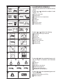
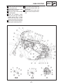
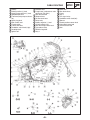
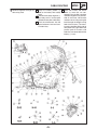
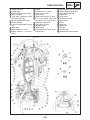
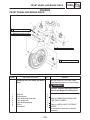
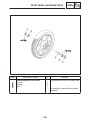
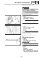
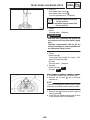
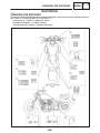
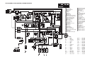
FOREWORD This Supplementary Service Manual has been prepared to introduce new service and data for the XVS1100A. For complete service information procedures it is necessary to use this Supplementary Service Manual together with the following manual. XVS1100L/XVS1100LC SERVICE MANUAL: LIT-11616-12-63 (5EL-28197-E0) XVS1100AM/XVS1100AMC SUPPLEMENTARY SERVICE MANUAL: LIT-11616-13-36 (5KS-28197-E0) EB000000 XVS1100AWR(C) XVS1100ATR(C) SUPPLEMENTARY SERVICE MANUAL 2002 by Yamaha Motor Co., Ltd. First edition, November 2002 All rights reserved. Any reproduction or unauthorized use without the written permission of Yamaha Motor Co., Ltd. is expressly prohibited. EAS00003 NOTICE This manual was produced by the Yamaha Motor Company, Ltd. primarily for use by Yamaha dealers and their qualified mechanics. It is not possible to include all the knowledge of a mechanic in one manual. Therefore, anyone who uses this book to perform maintenance and repairs on Yamaha Vehicles should have a basic understanding of mechanics and the techniques to repair these types of vehicles. Repair and maintenance work attempted by anyone without this knowledge is likely to render the vehicle unsafe and unfit for use. This model has been designed and manufactured to perform within certain specifications in regard to performance and emissions. Proper service with the correct tools is necessary to ensure that the vehicle will operate as designed. If there is any question about a service procedure, it is imperative that you contact a Yamaha dealer for any service information changes that apply to this model. This policy is intended to provide the customer with the most satisfaction from his vehicle and to conform with federal environmental quality objectives. Yamaha Motor Company, Ltd. is continually striving to improve all of its models. Modifications and significant changes in specifications or procedures will be forwarded to all authorized Yamaha dealers and will appear in future editions of this manual where applicable. This Service Manual contains information regarding periodic maintenance to the emission control system. Please read this material carefully. NOTE: Designs and specifications are subject to change without notice. IMPORTANT INFORMATION Particularly important information is distinguished in this manual by the following notations. The Safety Alert Symbol means ATTENTION! BECOME ALERT! YOUR SAFETY IS INVOLVED! WARNING CAUTION: NOTE: Failure to follow WARNING instructions could result in severe injury or death to the motorcycle operator, a bystander or a person inspecting or repairing the motorcycle. A CAUTION indicates special precautions that must be taken to avoid damage to the motorcycle. A NOTE provides key information to make procedures easier or clearer. EB002000 HOW TO USE THIS MANUAL MANUAL ORGANIZATION This manual consists of chapters for the main categories of subjects. (See “Illustrated symbols”) 1st title 1 : This is the title of the chapter with its symbol in the upper right corner of each page. 2nd title 2 : This title indicates the section of the chapter and only appears on the first page of each section. It is located in the upper right corner of the page. 3rd title 3 : This title indicates a sub-section that is followed by step-by-step procedures accompanied by corresponding illustrations. EXPLODED DIAGRAMS To help identify parts and clarify procedure steps, there are exploded diagrams at the start of each removal and disassembly section. 1. An easy-to-see exploded diagram 4 is provided for removal and disassembly jobs. 2. Numbers 5 are given in the order of the jobs in the exploded diagram. A number that is enclosed by a circle indicates a disassembly step. 3. An explanation of jobs and notes is presented in an easy-to-read way by the use of symbol marks 6 . The meanings of the symbol marks are given on the next page. 4. A job instruction chart 7 accompanies the exploded diagram, providing the order of jobs, names of parts, notes in jobs, etc. 5. For jobs requiring more information, the step-by-step format supplements 8 are given in addition to the exploded diagram and the job instruction chart. 2 1 6 3 8 5 4 7 EB003000 1 ILLUSTRATED SYMBOLS 2 GEN INFO SPEC 3 4 CHK ADJ ENG 5 6 CHAS CARB 7 8 TRBL SHTG ELEC 11 12 13 14 15 16 20 23 Symbols 9 to 16 indicate the following. 9 Serviceable with engine mounted 10 9 17 The following symbols are not relevant to every vehicle. Symbols 1 to 8 indicate the subject of each chapter. 1 General information 2 Specifications 3 Periodic checks and adjustments 4 Engine 5 Carburetor 6 Chassis 7 Electrical system 8 Troubleshooting 18 10 11 12 13 14 15 16 19 21 22 24 Filling fluid Lubricant Special tool Tightening torque Wear limit, clearance Engine speed Electrical data Symbols 17 to 22 in the exploded diagrams indicate the types of lubricants and lubrication points. 17 18 19 20 21 22 Engine oil Gear oil Molybdenum disulfide oil Wheel bearing grease Lithium soap base grease Molybdenum disulfide grease Symbols 23 to 24 in the exploded diagrams indicate the following: 23 Apply locking agent (LOCTITER) 24 Replace the part CONTENTS SPECIFICATIONS GENERAL SPECIFICATIONS . . . . . . . . . . . . . . . . . . . . . . . . . . . . . . . . . . MAINTENANCE SPECIFICATIONS . . . . . . . . . . . . . . . . . . . . . . . . . . . . . ENGINE . . . . . . . . . . . . . . . . . . . . . . . . . . . . . . . . . . . . . . . . . . . . . . . . . . CHASSIS . . . . . . . . . . . . . . . . . . . . . . . . . . . . . . . . . . . . . . . . . . . . . . . . . ELECTRICAL . . . . . . . . . . . . . . . . . . . . . . . . . . . . . . . . . . . . . . . . . . . . . CABLE ROUTING . . . . . . . . . . . . . . . . . . . . . . . . . . . . . . . . . . . . . . . . . . . . 1 2 2 2 3 5 PERIODIC CHECKS AND ADJUSTMENTS INTRODUCTION . . . . . . . . . . . . . . . . . . . . . . . . . . . . . . . . . . . . . . . . . . . . . . 15 PERIODIC MAINTENANCE CHART FOR THE EMISSION CONTROL SYSTEM . . . . . . . . . . . . . . . . . . . . . . . . . . . . . . . . . . . . . . . . . . . . . . . . . . . . . 15 GENERAL MAINTENANCE AND LUBRICATION CHART . . . . . . . . . 15 CHASSIS FRONT WHEEL AND BRAKE DISCS . . . . . . . . . . . . . . . . . . . . . . . . . . . REMOVING THE FRONT WHEEL . . . . . . . . . . . . . . . . . . . . . . . . . . . CHECKING THE FRONT WHEEL . . . . . . . . . . . . . . . . . . . . . . . . . . . . CHECKING THE BRAKE DISCS . . . . . . . . . . . . . . . . . . . . . . . . . . . . . INSTALLING THE FRONT WHEEL . . . . . . . . . . . . . . . . . . . . . . . . . . . REAR WHEEL AND BRAKE DISC . . . . . . . . . . . . . . . . . . . . . . . . . . . . . . MUFFLER AND BRAKE CALIPER . . . . . . . . . . . . . . . . . . . . . . . . . . . REAR WHEEL . . . . . . . . . . . . . . . . . . . . . . . . . . . . . . . . . . . . . . . . . . . . . REMOVING THE REAR WHEEL . . . . . . . . . . . . . . . . . . . . . . . . . . . . . CHECKING THE REAR WHEEL . . . . . . . . . . . . . . . . . . . . . . . . . . . . . CHECKING THE REAR WHEEL DRIVE HUB . . . . . . . . . . . . . . . . . INSTALLING THE REAR WHEEL . . . . . . . . . . . . . . . . . . . . . . . . . . . . 17 19 19 21 23 24 24 25 27 27 28 28 ELECTRICAL CHECKING THE SWITCHES . . . . . . . . . . . . . . . . . . . . . . . . . . . . . . . . . . . 30 XVS1100AWR(C)/XVS1100ATR(C) WIRING DIAGRAM GENERAL SPECIFICATIONS SPEC SPECIFICATIONS GENERAL SPECIFICATIONS Item Standard Model code XVS1100: 5KSJ (For U.S.A.) 5KSK (For CAL) 5KSU (For U.S.A.) 5KSV (For CAL) Dimensions Overall length Overall width Overall height Seat height Wheelbase Minimum ground clearance Minimum turning radius 2460 mm (96.9 in) 945 mm (37.2 in) 1,095 mm (43.1 in) 710 mm (28 in) 1645 mm (64.8 in) 140 mm (5.5 in) 3400 mm (133.9 in) Basic weight With oil and a full fuel tank 285 kg (628 lb) Tire Type Size Manufacturer Type front rear front rear front rear Tire pressure (cold tire) 0 X 90 kg (0 X 198 lb) load* front rear 90 kg (198 lb) X Maximum load* front rear Tubeless 130/90-16M/C 67S 170/80-15M/C 77S BRIDGESTONE/DUNLOP BRIDGESTONE/DUNLOP EXEDRA G703/D404F EXEDRA G702/D404G 225 kPa (2.25 kg/cm2, 32.6 psi) 250 kPa (2.5 kg/cm2, 36.3 psi) 225 kPa (2.25 kg/cm2, 32.6 psi) 250 kPa (2.5 kg/cm2, 36.3 psi) * Load is the total weight of the cargo, rider, passenger and accessories. –1– MAINTENANCE SPECIFICATIONS SPEC MAINTENANCE SPECIFICATIONS ENGINE Item Standard Carburetor I.D. mark Main jet Main air jet Jet needle Needle jet Pilot air jet (M.J) (M.A.J) (J.N) (N.J) (P.A.J.1) (P.A.J.2) Pilot outlet (P.O) Pilot jet (P.J) Bypass 1 (B.P.1) Bypass 2 (B.P.2) Bypass 3 (B.P.3) Valve seat size (V.S) Starter jet (G.S.1) Starter jet (G.S.2) Throttle valve size (Th.V) Fuel level (above the line on the float chamber) (F.L) Engine idle speed Intake vacuum Engine oil temperature Fuel pump Type Model/manufacturer Consumption amperage Output pressure <max> Limit 5EL5 40 (U.S.A.) 5EL6 50 (CAL) #1: #110, #2: #112.5 #55 5DL 43-53-1 P-0M #63.8 #145 1.0 #17.5 0.8 0.8 0.8 1.2 #42.5 0.8 #125 4 X 5 mm (0.16 X 0.20 in) SSS SSS SSS SSS SSS SSS SSS SSS SSS SSS SSS SSS SSS SSS SSS SSS SSS SSS 950 X 1,050 r/min 34.7 X 37.3 kPa (260 X 280 mmHg) 75 X 85_C (167 X 185_F) SSS SSS SSS Electrical type UC-Z61B/MITSUBISHI 0.8 A 12 kPa (0.12 kg/cm2,1.7 psi) SSS SSS SSS SSS CHASSIS Item Standard Front suspension Front fork travel Fork spring free length Fitting length Collar length Spring rate Stroke Optional spring Oil capacity Oil level Oil grade 140 mm (5.51 in) 371.9 mm (14.64 in) (K1) (K2) (K1) (K2) 334.4 mm (13.17 in) 183 mm (7.20 in) 4.41 N/mm (0.45 kg/mm, 25.18 lb/in) 6.37 N/mm (0.65 kg/mm, 36.37 lb/in) 0 X 77.5 mm (0 X 3.05 in) 77.5 X 140 mm (3.05 X 5.51 in) No 0.483 L (483 cm3, 17.01 Imp OZ, 16.34 US OZ) 104 mm (4.09 in) Fork oil 10WT or equivalent –2– Limit SSS 350 mm (13.78 in) SSS SSS SSS SSS SSS SSS SSS SSS SSS SSS MAINTENANCE SPECIFICATIONS Item Rear suspension Shock absorber travel Spring free length Fitting length Spring rate Stroke Optional spring Front wheel Type Rim size Rim material Rim runout limit Rear wheel Type Rim size Rim material Rim runout limit SPEC Standard Limit 51 mm (2.01 in) 181 mm (7.13 in) 169 mm (6.65 in) 132.3 N/mm (13.49 kg/mm, 755.43 lb/in) 0 X 51 mm (0 X 2.01 in) No SSS SSS SSS SSS SSS SSS radial Cast wheel 16M/C MT 3.00 Aluminum SSS lateral SSS SSS SSS SSS 1.0 mm (0.04 in) 0.5 mm (0.02 in) radial Cast wheel 15M/C MT4.50 Aluminum SSS lateral SSS (K1) (K1) SSS SSS SSS 1.0 mm (0.04 in) 0.5 mm (0.02 in) ELECTRICAL Item Standard Limit T.C.I. Pickup coil resistance/color T.C.I. unit model/manufacturer 189 X 231 Ω at 20_C (68_F)/Gray – Black SSS J4T142/MITSUBISHI SSS Rectifier/regulator Regulator type Model/manufacturer No load regulated voltage Rectifier capacity Withstand voltage Semi-conductor, short-circuit type SH678-11/SHINDENGEN 14.1 X 14.9 V 22 A 200 V –3– SSS SSS SSS SSS SSS MAINTENANCE SPECIFICATIONS Item Electric starter system Type Starter motor: Model/manufacturer Output Armature coil resistance Brush overall length Brush spring pressure SPEC Standard Limit Constant mesh type SSS SM-13/MITSUBA 0.6 kW 0.025 X 0.035 Ω at 20_C (68_F) 12.5 mm (0.49 in) SSS SSS SSS 4 mm (0.16 in) SSS 7.65 X 10.01 N (780 X 1021 g, 27.51 X 36.01 OZ) 28 mm (1.10 in) 0.7 mm (0.03 in) 27 mm (1.06 in) SSS MS5F-421 /JIDECO 180 A SSS SSS Starting circuit cut-off relay Model/manufacturer Coil resistance G8R-30Y-U/OMRON 202.5 X 247.5 Ω at 20_C (68_F) SSS Thermostat switch Model/manufacturer 5FU/NIPPON THERMOSTAT SSS Commutator diameter Mica undercut Starter relay: Model/manufacturer Amperage rating –4– CABLE ROUTING SPEC EB206000 CABLE ROUTING 1 2 3 4 5 6 7 8 9 10 11 12 Clutch cable Starter cable Handlebar switch lead (left) Handlebar switch lead (right) Spark plug lead Throttle cable Fuel hose (fuel cock to filter) Fuel breather hose (fuel tank roll over valve) (for CAL) Fuse box Alarm connector Fuel pump lead Speed sensor lead Sidestand switch lead Neutral switch lead Pickup coil lead To engine A.C. magneto lead Ventilation hose Sensing hose (AI system to carburetor joint) 20 Fuel hose (fuel pump to carburetor) 21 Clip 22 Brake hose 13 14 15 16 17 18 19 –5– 23 24 25 26 27 28 29 30 31 Heat protector Speedometer lead Wire harness Purge hose (carburetor to solenoid valve) (for CAL) Fitting plate Fuel hose (inlet) (fuel filter to fuel pump) Fuel hose (outlet) (fuel pump to carburetor) Alarm connector lead Wire harness CABLE ROUTING A Fasten the handlebar switch C Clamp the wire harness with the lead (left and right) to the handlehook of frame side. bar with plastic locking tie and D When installing the pipe of cut the end of tie. throttle cable press it inside. B Lay out the throttle and starter E Clamp the fuel hoses to the cables in three rows and secure frame with the clamp. them with a clip. (Two points at F Cross the fuel hose (fuel cock the front and rear.) Care should side) and fuel hose (carburetor be taken at this time so that the side) between guide of frame clip does not fall to the outside and clamp. (carburetor side is against the vertical face of the upper) vehicle. Point the opening part of G When connecting the sensing the clip to the inside of the vehose (carburetor joint to AI syshicle. tem) with a nozzle. –6– SPEC H Push the wire harness inside of the side cover. I Push the sensing hose inside of the tool box plate and not bend the sensing hose. J Through the wire harness of solenoid valve between AIS duct and fuel hose (for CAL). K Fasten the alarm lead with a plastic band on the tool box plate. L Fasten the sidestand switch lead to the bracket of tool box plate with plastic locking tie. CABLE ROUTING M Fasten the lead with locking tie near the side cover. N Position the all connectors inside of the connector cover. O Route the clutch cable through the cable guide. P Fasten the handlebar switch leads (left and right) under the handle crown with a plastic band. Set the band at four notches and install it no slacking. Q Route the each hoses through the frame guide and do not pinch it. R When installing the fitting plate, do not pinch the each hoses and wireharness. S When install the AI system push the wire harness to space of rearside. –7– SPEC CABLE ROUTING 1 2 3 4 5 6 7 8 9 10 11 12 Battery Battery positive (+) lead Starter motor positive (+) lead Speedometer lead Fuel hose (fuel pump to carburetor) Spark plug lead Main switch lead Throttle cable Front brake hose Handlebar switch lead (right) Headlight lead Ignition coil 13 Breather hose 14 Purge hose (carburetor to sole15 16 17 18 19 20 21 22 23 24 noid valve) (For CAL) Rear brake switch Reserve hose Air filter drain hose Delay relay Battery negative (–) lead Oil level switch lead Rear brake light switch lead Light reduce relay Rectifier/ regulator Stay 1 –8– 25 26 27 28 29 30 31 32 33 34 35 SPEC Down tube Rear brake hose Frame Stay 2 Turn signal relay Handlebar switch lead (left) Silencer Throttle position sensor lead Carburetor heater lead Thermo switch lead Horn CABLE ROUTING 36 Rectifire/ regulator and light (re- duce relay) lead A Clamp the battery positive (+) lead to the battery with battery band. B Connect the battery negative (–) lead and push it in to the space between battery box and battery. C Push the wireharness into the space between frame and starter motor relay. –9– SPEC D Route the harness and starter motor (+) lead, that are connected to the rectifier regulator and other equipment, by the outside of the frame side bracket and then secure it by passing the band through the weight saving hole of the bracket. (The securing point should be within 0 to 10 mm (0 to 0.39 in) right above the junction point of harness side leads that are connected with the battery (–) lead.) CABLE ROUTING SPEC E Connect the purge hose (carbu- J Fasten the wire harness, starter O Make sure to insert the rectifier retor side-solenoid valve side) motor positive (+) lead and batregulator coupler sufficiently unwith joint, knob is out side of frame. tery negative (–) lead to the til the sound is heard. F Route the front turn signal / posiframe with a plastic locking tie. P To rear brake. tion light lead and headlight lead K 70 mm (2.76 in) Q Fasten the rear brake switch through the rear of headlight L Fasten the rear brake switch lead lead with a band to down tube. body hole. and master cylinder reservoir (four point) G Connect the ignition coil lead at hose to the down tube with a plas- R Cutting part at the edge of the red tape to the right side. tic locking tie, and cut the end of band. H Knob of clip is rearside of body. locking tie and position is inside of S 30_ X 45_ I Fasten the rear brake switch frame. lead to the rear brake switch M 20 mm (0.79 in) (from bead end.) bracket with a plastic locking tie N Locate the band to forward of and cut of the end, inside of frame. down tube. –10– CABLE ROUTING T Fasten the oil level sensor lead V Arrange the throttle position senwith a locking tie to battery box. sor connector, carburetor heater Fix to the battery box with the connector and thermo switch band. To fix, align the band to the connector between the starting bottom of the box’s hole while fixcircuit cut off relay and high tening the lead to the back of the box sion code. (inside the body). The cutting part W Secure to the battery box with at the edge of the band comes to the band, cut the surplus section the front side of the body. and then point the locking secU Clamp the handlebar switch lead tion to the regulator side. (right) to the frame with a holder. The part to open and shut is outside of the body. –11– SPEC X Push the light reduce lead and the terminal-coupler lead for the carburetor heater into the deepest position in the groove of the battery box. CABLE ROUTING 1 2 3 4 5 6 7 8 9 10 11 Front brake hose Throttle cable Master cylinder reservoir hose Spark plug lead Purge hose (carburetor to solenoid valve) (for CAL) Rear brake light switch lead Rear brake hose Fuel hose (fuel pump to carburetor) Delay relay Battery negative (–) lead Battery negative (–) lead connector 12 13 14 15 16 17 18 19 20 21 22 Battery Battery positive (+) lead Tail/ brake light lead Starter relay Starter motor positive (+) lead Fuel tank breather hose (fuel tank to roll over valve) (for CAL) Fuel pump outlet hose Fuel pump inlet hose Ventilation hose Starter cable Sensing hose (AI system to carburetor joint) –12– 23 24 25 26 27 28 29 30 31 32 33 34 35 SPEC Fuel hose (fuel cock to fuel filter) Throttle position sensor lead Carburetor heater lead Tappet cover Clutch cable Thermo switch lead Wire harness Frame Igniter unit Igniter plate Fuel filter Tool box plate Speedometer lead connecter CABLE ROUTING SPEC A Clamp the throttle cables with F Route the battery positive (+) J Position the mark on the steel the holder. Position the end of lead through the slit of the batband to forward. clip downword. tery box. K Fasten the wire harness with a B Route the rear brake switch lead G Secure the igniter unit lead and band on the tool box plate. under the master cylinder resertail brake light lead to the frame L Fasten the wire harness to the vor hose. with a clamp. Point the frame with a plastic locking tie. C Position the band end of right open / close section to the upper Position the locking tie front of side bracket. side of the vehicle. the holder. D Position the steel band end to H To the rear fender. M Route the wire harness outside forward. I Connect the wire harness to the of the guide on the frame. E Position the steel band end to igniter unit through the hole of ig- N Clamp the clutch cable and startright side. niter plate. er cable with a holder. Position the end of holder down side. –13– CABLE ROUTING O Route the igniter lead through the igniter plate hole to the wireharness. P To the wire harness. Q Clamp the tail / brake light lead with mud guard clamp. R Clamp the tail / brake light lead with a holder on the mud guard. S Position the locking tie upward. T Forward. –14– SPEC INTRODUCTION/PERIODIC MAINTENANCE CHART FOR THE EMISSION CONTROL SYSTEM / GENERAL MAINTENANCE AND LUBRICATION CHART CHK ADJ EAS00036 PERIODIC CHECKS AND ADJUSTMENTS INTRODUCTION This chapter includes all information necessary to perform recommended checks and adjustments. If followed, these preventive maintenance procedures will ensure more reliable vehicle operation, a longer service life and reduce the need for costly overhaul work. This information applies to vehicles already in service as well as to new vehicles that are being prepared for sale. All service technicians should be familiar with this entire chapter. PERIODIC MAINTENANCE CHART FOR THE EMISSION CONTROL SYSTEM INITIAL NO. 1 * 2 ITEM REMARKS ODOMETER READINGS 600 mi (1,000 km) or 1 month 4,000mi (7,000 km) or 6 months 8,000 mi (13,000 km) or 12 months Ǹ Ǹ Ǹ Ǹ Ǹ Ǹ 12,000 mi (19,000 km) or 18 months 16,000 mi (25,000 km) or 24 months 20,000 mi (31,000 km) or 30 months Valve clearance S Check and adjust valve clearance when engine is cold. Spark plugs S Check condition. S Adjust gap and clean. S Replace at 8,000 mi (13,000 km) or 12 months and thereafter every 8,000 mi (13,000 km) or 12 months. Ǹ Replace. Ǹ Replace. Ǹ 3 * Crankcase ventilation system S Check ventilation hose for cracks or damage. S Replace if necessary. Ǹ Ǹ Ǹ Ǹ Ǹ 4 * Fuel line S Check fuel hoses for cracks or damage. S Replace if necessary. Ǹ Ǹ Ǹ Ǹ Ǹ 5 * Fuel filter S Replace initial 20,000 mi (31,000 km) and thereafter every 20,000 mi (31,000 km). 6 * Exhaust system S Check for leakage. S Tighten if necessary. S Replace gasket(s) if necessary. 7 * Carburetor synchronization S Adjust synchronization of carburetors. 8 * Idle speed S Check and adjust engine idle speed. S Adjust cable free play. 9 * Evaporative emission control system** S Check control system for damage. S Replace if necessary. Ǹ Ǹ Ǹ Ǹ Ǹ Ǹ Ǹ Ǹ Ǹ Ǹ Ǹ Ǹ Ǹ Ǹ Ǹ Ǹ Ǹ Ǹ Ǹ * Since these items require special tools, data and technical skills, have a Yamaha dealer perform the service. ** California only GENERAL MAINTENANCE AND LUBRICATION CHART INITIAL NO. 1 2 * 3 ITEM REMARKS 4,000mi (7,000 km) or 6 months 8,000 mi (13,000 km) or 12 months 12,000 mi (19,000 km) or 18 months 16,000 mi (25,000 km) or 24 months 20,000 mi (31,000 km) or 30 months Ǹ Ǹ Ǹ Ǹ Ǹ Engine oil S Replace. S Warm engine before draining. Ǹ Engine oil filter element S Replace. Ǹ Air filter element S Clean or replace if necessary. 4 * Brake system S Check operation fluid level, and fluid leakage. S Correct accordingly. S Replace pads if necessary. 5 * Clutch S Check operation. S Adjust or replace cable. 6 * Final gear oil S Check oil level and leakage. S Replace at initial 600 mi (1,000 km) or 1 month and thereafter every 18,000 mi (25,000 km) or 24 months. S Hypoid gear oil SAE 80 (API GL4) 7 * Control and meter cables S Apply chain, lube thoroughly. S Yamaha Chain and Cable Lube or engine oil SAE 10W-30 (API SE) ODOMETER READINGS 600 mi (1,000 km) or 1 month Ǹ Ǹ Ǹ Ǹ Ǹ Ǹ Ǹ Ǹ Ǹ Ǹ Ǹ Ǹ Ǹ Ǹ Ǹ Ǹ Ǹ Ǹ Ǹ Replace. Ǹ –15– Ǹ Check. Ǹ Ǹ Ǹ Ǹ Ǹ CHK ADJ GENERAL MAINTENANCE AND LUBRICATION CHART INITIAL NO. ITEM 600 mi (1,000 km) or 1 month REMARKS S Check swingarm pivot for play. S Correct if necessary. S Moderately repack every 16,000 mi (25,000 km) or 24 months with lithium-soap-based grease. ODOMETER READINGS 4,000mi (7,000 km) or 6 months 8,000 mi (13,000 km) or 12 months 12,000 mi (19,000 km) or 18 months 16,000 mi (25,000 km) or 24 months 20,000 mi (31,000 km) or 30 months 8 * Swingarm pivot shaft 9 * Rear suspension link pivots S Check operation. S Correct if necessary. 10 Brake and clutch lever pivot shafts S Apply chain lube thoroughly. S Lithium-soap-based grease. Ǹ Ǹ Ǹ Ǹ Ǹ 11 Brake pedal and shift pedal shafts S Apply chain lube thoroughly. S Lithium-soap-based grease. Ǹ Ǹ Ǹ Ǹ Ǹ 12 Sidestand pivot S Check operation. S Lubricate and repair if necessary. S Lithium-soap-based grease. Ǹ Ǹ Ǹ Ǹ Ǹ Front fork S Check operation and for oil leakage. S Correct accordingly. Ǹ Ǹ Ǹ Ǹ Ǹ Ǹ Ǹ Ǹ Repack. Ǹ 13 * Repack. Ǹ Ǹ 14 * Steering bearings S Check bearing play and steering for smooth operation. S Correct if necessary. S Moderately repack every 18,000 mi (25,000 km) or 24 months with lithium-soap-based grease. 15 * Wheel bearings S Check bearings for looseness and damage. S Replace if necessary. Ǹ Ǹ Ǹ Ǹ Ǹ 16 * Wheels S Check runout and for damage. Ǹ Ǹ Ǹ Ǹ Ǹ Ǹ Ǹ Ǹ Ǹ Ǹ 17 * Sidestand switch S Check operation. S Replace if necessary. 18 * Tires S Check tire tread wear and for damage. S Replace if necessary. Ǹ Ǹ Ǹ Ǹ Ǹ 19 * Shock absorber assembly S Check operation and for oil leakage. S Replace if necessary. Ǹ Ǹ Ǹ Ǹ Ǹ 20 * Chassis fasteners S Make sure that all nuts, bolts and screws are properly tightened. S Tighten if necessary. Ǹ Ǹ Ǹ Ǹ Ǹ 21 * Throttle grip housing and cable S Check operation and free play. S Adjust the throttle cable free play if necessary. S Lubricate the throttle grip housing and cable. Ǹ Ǹ Ǹ Ǹ Ǹ Ǹ Ǹ * Since these items require special tools, data and technical skills, have a Yamaha dealer perform the service. NOTE: From 24,000 mi (37,000 km) or 36 months, repeat the maintenance intervals starting from 4,000 mi (7,000 km) or 6 months. NOTE: F Air filter S This model’s air filter is equipped with a disposable oil-coated paper element, which must not be cleaned with compressed air to avoid damaging it. S The air filter element needs to be replaced more frequently when riding in unusually wet or dusty areas. F Hydraulic brake service S After disassembling the brake master cylinders and calipers, always change the fluid. Regularly check the brake fluid levels and fill the reservoirs as required. S Every two years replace the internal components of the brake master cylinders and calipers, and change the brake fluid. S Replace the brake hoses every four years and if cracked or damaged. F Engine oil type S Yamalube 4 ( 20W-40) or engine oil SAE 20W-40 (API SE) for temperatures of 5_C (40_F) or above. S Yamalube 4 (10W-30) or engine oil SAE 10W-30 (API SE) for temperatures of 15_C (60_F) or below. –16– FRONT WHEEL AND BRAKE DISCS CHAS CHASSIS FRONT WHEEL AND BRAKE DISCS 59 Nm (5.9 mSkg, 43 ftSlb) 20 Nm (2.0 mSkg, 14 ftSlb) 40 Nm (4.0 mSkg, 29 ftSlb) 23 Nm (2.3 mSkg, 17 ftSlb) Order Job name/Part name Q’ty Remarks Remove the parts in the order listed. Stand the motorcycle on a level surface. Removing the front wheel and brake discs WARNING Securely support the motorcycle so there is no danger of it falling over. 1 2 3 4 5 6 7 Reflector Brake calipers Front wheel axle pinch bolt Front wheel axle Front wheel assembly Collars Brake discs 2 2 1 1 1 2 2 –17– Refer to “REMOVING/INSTALLING THE FRONT WHEEL”. Refer to “INSTALLING THE FRONT WHEEL”. For installation, reverse the removal procedure. FRONT WHEEL AND BRAKE DISCS Order 1 2 3 Job name/Part name Disassembling the front wheel Oil seals Bearings Collar Q’ty CHAS Remarks Disassemble the parts in the order listed. 2 2 1 For assembly, reverse the disassembly procedure. –18– FRONT WHEEL AND BRAKE DISCS CHAS EAS00521 REMOVING THE FRONT WHEEL 1. Stand the motorcycle on a level surface. WARNING Securely support the motorcycle so that there is no danger of it falling over. NOTE: Place the motorcycle on a suitable stand so that the front wheel is elevated. 2. Remove: S reflectors 1 (left and right) S brake calipers 2 (left and right) NOTE: Do not squeeze the brake lever when removing the brake calipers. 3. Loosen: S pinch bolt (front wheel axle) 1 S front wheel axle 2 4. Elevate: S front wheel NOTE: Place the motorcycle on a suitable stand so that the front wheel is elevated. EAS00526 CHECKING THE FRONT WHEEL 1. Check: S wheel axle Roll the wheel axle on a flat surface. Bends ! Replace. WARNING Do not attempt to straighten a bent wheel axle. 2. Check: S tire S front wheel Damage/wear ! Replace. Refer to “CHECKING THE TIRES” and “CHECKING THE WHEELS” in chapter 3. –19– FRONT WHEEL AND BRAKE DISCS CHAS 3. Measure: S front wheel radial runout 1 S front wheel lateral runout 2 Over the specified limits ! Replace. Front wheel radial runout limit 1.0 mm (0.04 in) Front wheel lateral runout limit 0.5 mm (0.02 in) 4. Check: S collars Damage/wear ! Replace. WARNING S New tires have a relatively low grip on the road surface until they have been slightly worn. Therefore, approximately 100 km (62 mi) should be traveled at normal speed before any highspeed riding is done. 5. Check S wheel bearings Front wheel turns roughly or is loose ! Replace the wheel bearings. S oil seals Damage/wear ! Replace. 6. Replace: S wheel bearings New S oil seals New a. Clean the outside of the front wheel hub. b. Remove the oil seals 1 with a flat-head screwdriver. NOTE: To prevent damaging the wheel, place a rag between the screwdriver and the wheel surface. c. Remove the wheel bearings with a general bearing puller 2 . d. Install the new wheel bearings and oil seals in the reverse order of disassembly. –20– FRONT WHEEL AND BRAKE DISCS CHAS CAUTION: Do not contact the wheel bearing center race 4 or balls 5 . Contact should be made only with the outer race 6 . NOTE: Use a socket 3 that matches the diameter of the wheel bearing outer race and oil seal. EAS00531 CHECKING THE BRAKE DISCS The following procedure applies to all of the brake discs. 1. Check: S brake disc Damage/galling ! Replace. 2. Measure: S brake disc deflection 1 Out of specification ! Correct the brake disc deflection or replace the brake disc. Brake disc deflection limit (maximum) Front: 0.15 mm (0.006 in) Rear: 0.15 mm (0.006 in) a. Place the motorcycle on a suitable stand so that the wheel is elevated. b. Before measuring the front brake disc deflection, turn the handlebar to the left or right to ensure that the front wheel is stationary. c. Remove the brake caliper. d. Hold the dial gauge at a right angle against the brake disc surface. e. Measure the deflection 2 X 3 mm (0.078 X 0.12 in) below the edge of the brake disc. –21– FRONT WHEEL AND BRAKE DISCS CHAS 3. Measure: S brake disc thickness Measure the brake disc thickness at a few different locations. Out of specification ! Replace. Brake disc thickness limit (minimum) Front: 4.5 mm (0.18 in) Rear: 5.5 mm (0.22 in) 4. Adjust: S brake disc deflection a. Remove the brake disc. b. Rotate the brake disc by one bolt hole. c. Install the brake disc. NOTE: Tighten the brake disc bolts in stages and in a crisscross pattern. Brake disc bolt 23 Nm (2.3 mSkg, 17 ftSlb) LOCTITE d. Measure the brake disc deflection. e. If out of specification, repeat the adjustment steps until the brake disc deflection is within specification. f. If the brake disc deflection cannot be brought within specification, replace the brake disc. –22– CHAS FRONT WHEEL AND BRAKE DISCS EAS00544 INSTALLING THE FRONT WHEEL The following procedure applies to both brake discs. 1. Lubricate: S wheel axle S oil seallips Recommended lubricant Lithium soap base grease 2. Install: S front wheel assembly NOTE: The arrow mark a on the tire must point in the direction of the wheel. 3. Tighten: 59 Nm (5.9 mSkg, 29 ftSlb) S wheel axle 1 S wheel axle pinch bolt 2 20 Nm (2.0 mSkg, 14 ftSlb) CAUTION: Before tightening the wheel axle nut, push down hard on the handlebar several times and check if the front fork rebounds smoothly. 4. Install: S brake calipers S reflectors 40 Nm (4.0 mSkg, 29 ftSlb) WARNING Make sure that the brake hose is routed properly. –23– CHAS REAR WHEEL AND BRAKE DISC REAR WHEEL AND BRAKE DISC MUFFLER AND BRAKE CALIPER 20 Nm (2.0mSkg, 14 ftSlb) 30 Nm (3.0mSkg, 22 ftSlb) 40 Nm (4.0mSkg, 29 ftSlb) 25 Nm (2.5mS kg, 18 ftSlb) Order 1 2 3 4 Job name/Part name Removing the muffler and brake caliper Muffler Muffler stay Brake hose holder Brake caliper Q’ty 20 Nm (2.0mSkg, 14 ftSlb) Remarks Remove the parts in the order listed. 1 1 1 1 –24– Refer to “REMOVING THE REAR WHEEL”. For installation, reverse the removal procedure. REAR WHEEL AND BRAKE DISC CHAS REAR WHEEL 23 Nm (2.3mSkg, 17 ftSlb) 40 Nm (4.0mSkg, 29 ftSlb) 23 Nm (2.3mSkg, 17 ftSlb) 74 Nm (7.4mSkg, 54 ftSlb) 107 Nm (10.7mSkg, 77 ftSlb) Order Job name/Part name Q’ty Remarks Remove the parts in the order listed. Removing the rear wheel WARNING Securely support the motorcycle so there is no danger of it falling over. Drain Refer to “FINAL GEAR OIL REPLACEMENT” in CHAPTER 3. Refer to “FUEL TANK AND SEATS” in CHAPTER 3. Loosen Final gear oil Fuel tank and seats 1 2 3 4 5 6 7 Rear fender assembly Brake caliper bracket bolt Bolts Rear axle nut/washer Rear axle end nuts/axle holder Rear wheel assembly Washer Collar 1 4 1/1 2/1 1 1 1 –25– Refer to “REMOVING/INSTALLING THE REAR WHEEL”. For installation, reverse the removal procedure. REAR WHEEL AND BRAKE DISC CHAS 62 Nm (6.2mSkg, 45 ftSlb) Order 1 2 3 4 5 6 7 8 Job name/Part name Rear wheel disassembly Disassembling the rear wheel Lock washers Clutch hub Dampers O-rings Oil seal Bearing Spacer Bearings Q’ty Remarks Remove the parts in the order listed. 2 1 6 2 1 1 1 2 For assembly, reverse the disassembly procedure. –26– REAR WHEEL AND BRAKE DISC CHAS EAS00562 REMOVING THE REAR WHEEL 1. Stand the motorcycle on a level surface. WARNING Securely support the motorcycle so that there is no danger of it falling over. NOTE: Place the motorcycle on a suitable stand so that the rear wheel is elevated. 2. Remove: S rear gear case fitting bolts 3. Remove: S brake caliper 1 S brake caliper bracket bolt NOTE: Do not depress the brake pedal when removing the brake caliper. 4. Remove: S wheel axle nut S washer 5. Remove: S rear axle end nut 2 6. Remove: S rear axle holder 3 7. Remove: S rear wheel EAS00566 CHECKING THE REAR WHEEL 1. Check: S wheel axle S rear wheel S wheel bearings S oil seals Refer to “FRONT WHEEL AND BRAKE DISCS”. 2. Check: S tire Damage/wear ! Replace. Refer to “CHECKING THE TIRES” in chapter 3. 3. Measure: S rear wheel radial runout S rear wheel lateral runout Refer to “FRONT WHEEL AND BRAKE DISCS”. –27– REAR WHEEL AND BRAKE DISC CHAS EAS00567 CHECKING THE REAR WHEEL DRIVE HUB 1. Check: S rear wheel drive hub Cracks/damage ! Replace. S rear wheel drive hub dampers Damage/wear ! Replace. EAS00572 INSTALLING THE REAR WHEEL 1. Lubricate: S drive shaft splines Recommended lubricant Molybdenum disulfide grease 2. Lubricate: S wheel axle S wheel bearings S oil seal lips Recommended lubricant Lithium soap base grease 3. Install: S rear wheel assembly a. Install the rear wheel assembly 1 with the rear brake caliper bracket 2 and hold the bracket to keep the specified position. b. After installation of the rear axle shaft 3 , slide the wheel assembly to forward direction. c. To make sure the caliper bracket mounts on the swingarm and then, fix the holder of swingarm temporally. NOTE: The holder should installed with the punch mark a facing upper. d. Tighten the rear gear housing bolts, with specified tightening torque. Rear gear housing bolt 70 Nm (7.0 mSkg, 51 ftSlb) e. Tighten the nut of rear axle shaft with specified torque. Wheel axle nut 107 Nm (10.7 mSkg, 77 ftSlb) –28– REAR WHEEL AND BRAKE DISC CHAS f. Tighten the rear axle holder with specified torque. Rear axle end nut 23 Nm (2.3 mSkg, 17 ftSlb) g. Tighten the rear brake caliper bracket bolt with specified tightening torque. Brake caliper bracket bolt 40 Nm (4.0 mSkg, 29 ftSlb) h. Install the rear brake caliper on the bracket and tighten the bolts with specified tightening torque. Brake caliper bolt 40 Nm (4.0 mSkg, 29 ftSlb) –29– CHECKING THE SWITCHES ELEC ELECTRICAL EAS00731 CHECKING THE SWITCHES Check each switch for damage or wear, proper connections, and also for continuity between the terminals. Refer to “CHECKING SWITCH CONTINUITY”. Damage/wear ! Repair or replace the switch. Improperly connected ! Properly connect. Incorrect continuity reading ! Replace the switch. –30– CHECKING THE SWITCHES 1 2 3 4 5 6 Clutch switch Horn switch Dimmer switch Turn signal switch Main switch Front brake switch 7 8 9 10 11 12 Engine stop switch Start switch Fuse Rear brake switch Sidestand switch Neutral switch –31– ELEC PRINTED IN U.S.A. XVS1100AWR(C)/XVS1100ATR(C) WIRING DIAGRAM 1 2 3 4 5 6 7 8 9 10 11 12 13 14 15 16 17 18 19 20 21 22 23 24 25 26 27 28 29 Pickup coil A.C. magneto Rectifier/ regulator Main switch Solenoid Battery Main fuse Starter relay Starter motor Starting circuit cut-off relay Oil level warning light relay Right handlebar switch Front brake light switch Engine stop switch Start switch Oil level gauge Sidestand switch Fuel pump Throttle position sensor Igniter unit Ignition coil Spark plug Speed sensor Meter assembly Oil level warning light Engine trouble warning light Speedometer Meter light Turn signal indicator light 30 31 32 33 34 35 36 37 38 39 40 41 42 43 44 45 46 47 48 49 50 51 52 53 54 55 56 Neutral indicator light High beam indicator light Neutral switch Trip switch Turn signal relay Horn Rear brake light switch Left handlebar switch Dimmer switch Horn switch Clutch switch Turn signal switch Headlight Front turn signal light (left) Front turn signal light (right) Rear turn signal light (left) Rear turn signal light (right) Tail/ brake light Ignition fuse Backup fuse Headlight fuse Signal fuse Carburetor heater fuse Thermo switch Carburetor heater 1 Carburetor heater 2 Carburetor heater earth COLOR CODE B ......... Br . . . . . . . . Ch . . . . . . . Dg . . . . . . . G ........ Gy . . . . . . . L ......... Lg . . . . . . . . O ........ P ......... R......... Sb . . . . . . . . W ........ Y ......... B/ L . . . . . . . B/ R . . . . . . B/ W . . . . . . B/ Y . . . . . . Black Brown Chocolate Dark green Green Gray Blue Light green Orange Pink Red Sky blue White Yellow Black/ Blue Black/ Red Black/ White Black/ Yellow Br/ B . . . . . . Br/ L . . . . . . Br/ W . . . . . Br/ Y . . . . . . L /B . . . . . . . L/G . . . . . . L/R . . . . . . L/W . . . . . . L/Y . . . . . . . R/ B . . . . . . R/ G . . . . . . R/ W . . . . . . R/ Y . . . . . . Sb/ W . . . . . W/ B . . . . . . W/ G . . . . . . Y/ L . . . . . . . Y/ R . . . . . . Brown/ Black Brown/ Blue Brown/ White Brown/ Yellow Blue/ Black Blue/ Green Blue/ Red Blue/ White Blue/ Yellow Red/ Black Red/ Green Red/ White Red/ Yellow Sky blue / White White/ Black White/ Green Yellow/ Blue Yellow/ Red


![Manuale Officina [ ITA ] Yamaha R1 2002-2003](http://vs1.manualzilla.com/store/data/006110674_1-52d32bbc9127defc0419b49b1226ec2b-150x150.png)