1
Signamax 065-1600 series
User's Manual
Managed Media Converter
Release 1.04
Table of Contents
CAUTION--------------------------------------------------------------------------------------------------------- VI
ELECTRONIC EMISSION NOTICES ---------------------------------------------------------------------------- VI
CHAPTER 1. INTRODUCTION ------------------------------------------------------------------------------ 2
1-1. OVERVIEW -------------------------------------------------------------------------------------------------- 2
1-2. FEATURES -------------------------------------------------------------------------------------------------- 2
1-3. CHECKLIST ------------------------------------------------------------------------------------------------- 3
1-4. VIEW OF THE CONVERTER ------------------------------------------------------------------------------- 4
1-4-1. User Interfaces on the Front View (Button, LEDs and Plugs) -------------------------- 4
1-4-2. User Interfaces on the Rear Panel View ---------------------------------------------------- 5
CHAPTER 2. INSTALLATION-------------------------------------------------------------------------------- 6
2-1. NETWORK SYSTEM W IDE BASIC CONFIGURATION --------------------------------------------------- 6
2-2. STARTING THE SIGNAMAX 065-1600 SERIES MANAGED MEDIA CONVERTER UP ----------------- 9
2-2-1. Battery Installation (For RC-2202 Only) ----------------------------------------------------- 9
2-2-2. Cable and Hardware Installation -------------------------------------------------------------11
2-2-3. Management Station Installation ------------------------------------------------------------ 12
2-2-3-1. Installing the Management Station through the Signamax 065-1600 series’
RS-232 Port ------------------------------------------------------------------------------------------- 13
2-2-3-2. Installing the Management Station through the Signamax 065-1600 series’
TP Port-------------------------------------------------------------------------------------------------- 15
2-2-3-3. Installing the Management Station through the Signamax 065-1600 series’
Fiber Port via a Central Site Converter Chassis ---------------------------------------------- 17
2-2-4. IP Address Assignment ------------------------------------------------------------------------ 18
CHAPTER 3. OPERATION OF WEB-BASED MANAGEMENT ---------------------------------- 23
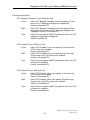
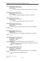
3-1. W EB MANAGEMENT HOME OVERVIEW --------------------------------------------------------------3-2. THE FUNCTION TREE IN W EB MANAGEMENT ------------------------------------------------------3-3. PORT STATUS AND COUNTER-------------------------------------------------------------------------3-4. CONFIGURATION ----------------------------------------------------------------------------------------3-4-1. System Configuration -------------------------------------------------------------------------3-4-1-1. Username / Password Setting --------------------------------------------------------3-4-1-2. IP Configuration --------------------------------------------------------------------------3-4-1-3. System Time Setting --------------------------------------------------------------------3-4-1-4. Location/Contact Setting ---------------------------------------------------------------3-4-1-5. TP Port Management -------------------------------------------------------------------3-4-1-6. Power Down Setting --------------------------------------------------------------------3-4-2. SNMP Configuration---------------------------------------------------------------------------3-4-3. Max. Packet Length Setting -----------------------------------------------------------------3-4-4. Broadcasting Suppression -------------------------------------------------------------------3-4-5. Misc. Feature Configuration -----------------------------------------------------------------3-4-6. Spanning Tree Configuration ----------------------------------------------------------------3-4-6-1. STP Status---------------------------------------------------------------------------------3-4-6-2. STP Configuration -----------------------------------------------------------------------3-4-7. Filtering Configuration ------------------------------------------------------------------------3-4-8. VLAN Configuration ---------------------------------------------------------------------------3-4-9. Trap/Alarm Configuration --------------------------------------------------------------------3-4-10. Save Configuration----------------------------------------------------------------------------
24
27
29
37
38
38
39
42
46
47
48
49
52
53
54
57
57
59
64
69
71
79
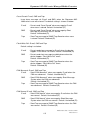
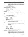
3-5. DIAGNOSTICS -------------------------------------------------------------------------------------------3-6. SHOW LOG DATA ---------------------------------------------------------------------------------------3-7. SOFTWARE UPGRADE ---------------------------------------------------------------------------------3-8. REBOOT -------------------------------------------------------------------------------------------------3-9. LOGOUT---------------------------------------------------------------------------------------------------
82
86
93
95
96
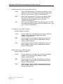
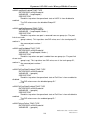
CHAPTER 4. OPERATION OF MENU-DRIVEN CONSOLE -------------------------------------- 97
4-1. TEXT-BASED MENU-DRIVEN MANAGEMENT OVERVIEW ------------------------------------------- 98
4-2. THE FUNCTION TREE IN CONSOLE MANAGEMENT ------------------------------------------------ 101
4-3. PORT STATUS AND COUNTER------------------------------------------------------------------------- 103
4-4. CONFIGURATION ---------------------------------------------------------------------------------------- 111
4-4-1. System Configuration ------------------------------------------------------------------------- 112
4-4-1-1. Create Username / Password -------------------------------------------------------- 112
4-4-1-2. Change Username / Password ------------------------------------------------------- 113
4-4-1-3. IP Configuration -------------------------------------------------------------------------- 115
4-4-1-4. System Time Setting -------------------------------------------------------------------- 117
4-4-1-5. Location/Contact Setting --------------------------------------------------------------- 122
4-4-1-6. TP Port Management ------------------------------------------------------------------- 123
4-4-1-7. Power Down Setting -------------------------------------------------------------------- 124
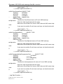
4-4-2. SNMP Configuration--------------------------------------------------------------------------- 125
4-4-3. Packet Length----------------------------------------------------------------------------------- 130
4-4-4. Broadcasting Suppression ------------------------------------------------------------------- 131
4-4-5. Spanning Tree Configuration ---------------------------------------------------------------- 132
4-4-5-1. STP Enable/Disable--------------------------------------------------------------------- 132
4-4-5-2. STP Status--------------------------------------------------------------------------------- 133
4-4-5-3. STP Configuration ----------------------------------------------------------------------- 135
4-4-6. Misc. Feature Configuration ----------------------------------------------------------------- 139
4-4-7. Filtering Configuration ------------------------------------------------------------------------ 144
4-4-8. VLAN Configuration --------------------------------------------------------------------------- 150
4-4-9. Trap/Alarm Configuration -------------------------------------------------------------------- 152
4-4-10. Save Configuration--------------------------------------------------------------------------- 160
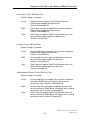
4-5. DIAGNOSTICS ------------------------------------------------------------------------------------------- 163
4-6. SHOW LOG DATA --------------------------------------------------------------------------------------- 167
4-7. SOFTWARE UPGRADE --------------------------------------------------------------------------------- 174
4-8. REBOOT ------------------------------------------------------------------------------------------------- 176
4-9. LOGOUT-------------------------------------------------------------------------------------------------- 177
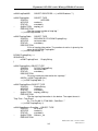
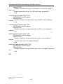
CHAPTER 5. MAINTENANCE ---------------------------------------------------------------------------- 178
5-1. RESOLVING NO LINK CONDITIONS ------------------------------------------------------------------- 178
5-2. Q&A------------------------------------------------------------------------------------------------------ 178
APPENDIX A TECHNICAL SPECIFICATIONS ------------------------------------------------------- 179
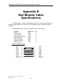
APPENDIX B NULL MODEM CABLE SPECIFICATIONS----------------------------------------- 184
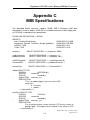
APPENDIX C MIB SPECIFICATIONS ------------------------------------------------------------------ 185
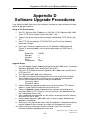
APPENDIX D SOFTWARE UPGRADE PROCEDURES ------------------------------------------- 225
Revision History
Release
Date
Revision
1.00
10/15/2005
A1
Caution
Circuit devices are sensitive to static electricity, which can damage their delicate electronics.
Dry weather conditions or walking across a carpeted floor may cause you to acquire a static
electrical charge.
To protect your device, always:
• Touch the metal chassis of your computer to ground the static electrical charge before
you pick up the circuit device.
• Pick up the device by holding it on the left and right edges only.
Electronic Emission Notices
Federal Communications Commission (FCC) Statement
This equipment has been tested and found to comply with the limits for a class A computing
device pursuant to Subpart J of part 15 of FCC Rules, which are designed to provide
reasonable protection against such interference when operated in a commercial environment.
European Community (CE) Electromagnetic Compatibility Directive
This equipment has been tested and found to comply with the protection requirements of
European Emission Standard EN55022/EN60555-2 and the Generic European Immunity
Standard EN50082-1.
EMC:
EN55022(1988) /CISPR-22(1985)
class A
EN60555-2(1995)
class A
EN60555-3
IEC1000-4-2(1995)
4K V CD, 8KV, AD
IEC1000-4-3(1995)
3V/m
IEC1000-4-4(1995)
1KV – (power line), 0.5KV – (signal line)
About this user’s manual
In this user’s manual, it will not only tell you how to install and connect your network
system but configure and monitor the Signamax 065-1600 series through the built-in
console and web by RS-232 serial interface and Ethernet ports step-by-step. Many
explanations in detail of hardware and software functions are shown as well as the
examples of the operation for web-based interface and text-based menu-driven
console interface.
Overview of this user’s manual
Chapter 1 “Introduction” describes the features of Signamax 065-1600 series
Chapter 2 “Installation”
Chapter 3 “Operation of Web-based Management”
Chapter 4 “Operation of Menu-driven Console”
Chapter 5 “Maintenance”
Publication date: October, 2005
Revision 1.0
1
Signamax 065-1600 series managed media converter
1. Introduction
1-1. Overview
The Signamax 065-1600 series media converter is designed to convert
twisted pair 10/100/1000BaseT/TX media to and from 1000BaseLX/SX Gigabit
Ethernet fiber optic media. With the device’s SNMP agent, web-based management,
and Telnet text-based Command Line Interface (CLI) management, the network
administrator can logon to the converter to monitor, configure and control the activity
of each port. In addition, the converter implements bandwidth rating management
capability via its intelligent software. The overall network management is enhanced,
and the network efficiency is also improved to accommodate and deliver high
bandwidth applications.
1-2. Features
The Signamax 065-1600 series converter provides the following features for
users to perform system network administration.
Management
• Port Status, Counter, and Configuration.
• Display the basic System Information on the user interface (UI).
• System configuration which includes administrator, guest users and IP address
relative to operating parameters and SNMP basic parameters.
• Maximum packet length can be up to 1536 bytes.
• Broadcast suppression, to allow for smooth recovery from power loss while a
number of managed converters are sending broadcast messages for DHCP
requests simultaneously.
• The trap events alarm can be sent via e-mail and mobile phone short (text)
message. It includes Case Intrusion Detection.
• A configured setting can be saved into the on-board flash memory. The current
setting can be recovered from the default setting or the previous configured
setting.
• On-board diagnostics function provides the hardware status to the
administrator.
• On-board firmware can be updated via TFTP functionality.
• The converter allows administrator to reboot the system from the management
station.
• The converter will log the last 120 records in the main memory and display
them on the local console.
Publication date: October, 2005
Revision 1.0
2
Signamax 065-1600 series Managed Media Converter
1-3. Checklist
Before you start installing the converter, please verify that the package contains the
following:
A set of SNMP-enabled Managed Media Converter
AC-DC Power Adapter
RS-232 Cable
Plastic Pads
Battery for RC-2202 only
This User's Manual
Please notify your sales representative immediately if any of the aforementioned
items is missing or damaged.
Publication date: October, 2005
Revision 1.0
3
Signamax 065-1600 series managed media converter
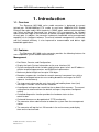
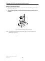
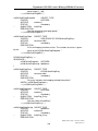
1-4. View of the Converter
Fig. 1-1 Full View of the Managed Media Converter
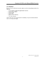
1-4-1. User Interfaces on the Front View (Button, LEDs and Plugs)
TP Port Status Indication LEDs
TP Cable Plug
Fiber Port Status Indication LEDs
Fiber Cable Plug
Reset Switch for the Managed
Media Converter:
Reset Switch is used to initialize
or reset the management
system.
Power Indication LED
Fig. 1-2 Front View of the Managed Media Converter
Publication date: October, 2005
Revision 1.0
4
Signamax 065-1600 series Managed Media Converter
LED Indicators
LED
Color
Function
System LED
Green Lit when +5V power is on and good
Lit when CPU is on and good
Green
CPU/Loop
Blinks when loop test is present
Power
10/100/1000Mbps Ethernet TP Port LED
Lit when 1000Mbps connection with remote device is good
Link1000 Green Off when 10/100Mbps connection with remote device is good
or cable connection is not good
ACT
Green Blinks when any traffic is present
Lit when full-duplex mode is active
Amber Off when half-duplex mode is active
FDX/COL
Blinks when any collision is present
1000Mbps Fast Ethernet FX Port LED
Lit when connection with remote device is good
Link/ACT Green Blinks when any traffic is present
Off when cable connection is not good
Table1-1
1-4-2. User Interfaces on the Rear Panel View
The serial port cable is attached directly to a DCE device through RS-232
cable for console management.
5V DC Jack
RS232 DB-9 Connector
Fig. 1-3 Rear View of the Managed Media Converter
Publication date: October, 2005
Revision 1.0
5
Signamax 065-1600 series managed media converter
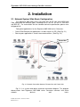
2. Installation
2-1. Network System Wide Basic Configuration
The Signamax 065-1600 series Converter has RJ-45 with auto MDIX and
Fiber connection for different types, including SC/ST, MT-RJ, VF-45, LC, BiDi-SFP
and BiDi-SC. For more details on the standard technical specification, please refer
to Appendix A.
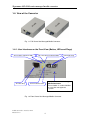
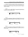
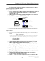
Two typical applications for the Signamax 065-1600 series Converter:
Central Site/Remote site application is used in carrier or ISP. (See Fig. 2-1)
Peer-to-peer application is used in two remote offices. (See Fig. 2-2)
Central Site
Fig. 2-1 Network Connection between Remote Site and Central Site
Fig. 2-1 is a system wide basic reference connection diagram. This diagram
demonstrates how Signamax 065-1600 series Converter connects with other
network
devices
and
hosts.
Publication date: October, 2005
Revision 1.0
6
Signamax 065-1600 series Managed Media Converter
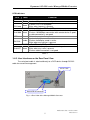
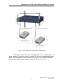
Fig. 2-2 Single-mode Fiber Optic Network Configuration
The Managed Media Converter embedded web server, SNMP agent and
Telnet software, etc. can be used at a remote PC with any installed web browser,
SNMP or Telnet application to do network management. PC Web/SNMP Network
Management station can be installed at either the central or user site.
Publication date: October, 2005
Revision 1.0
7
Signamax 065-1600 series managed media converter
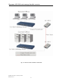
Fig. 2-3 Office-to-Office Network Connection
Publication date: October, 2005
Revision 1.0
8
Signamax 065-1600 series Managed Media Converter
2-2. Starting Signamax 065-1600 series up
This section will give users a quick start for:
- Battery Installation (For RC-2202 Only)
- Cable and Hardware Installation
- Management Station Installation
- Software booting and configuration
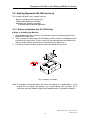
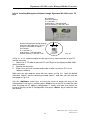
2-2-1. Battery Installation (For RC-2202 Only)
Ways of Installing the Battery:
1. After powering off the converter, unscrew the vacant slot dummy panel at the
bottom of the converter.
2. Then, connect the connectors of the battery and the socket at the bottom of the
converter with each other. (Please note that the red cord must be linked to the
red one and the black cord also must be linked to the black one.)
3. Fasten the vacant slot dummy panel and then reboot the converter.
Fig. 2-4 Battery Installation
Note: The battery cannot be taken out when the converter is powered on. If you
would like to replace the battery, you should power the converter off in
advance and then reboot it again after completing the installation of battery.
Publication date: October, 2005
Revision 1.0
9
Signamax 065-1600 series managed media converter
Ways
of Unloading the Battery:
1. After powering off the converter, unscrew the vacant slot dummy panel at the
bottom of the converter.
2. You can unload the battery after disconnecting the battery connector from the
converter.
Fig. 2-5 Unload the Battery from the Converter
Note: The battery will be charged automatically after you had installed it and
rebooted the converter.
Publication date: October, 2005
Revision 1.0
10
Signamax 065-1600 series Managed Media Converter
2-2-2. Cable and Hardware Installation
⇒ Wear a grounding device for electrostatic discharge
⇒ Verify that the AC-DC adapter conforms to your country AC power requirement
and then insert the power plug
• TP Cable
⇒ Use Cat. 5 TP cable to connect server/host or workstation to TP port of the
converter
⇒ TP port supports MDI/MDI-X auto-crossover, use:
straight-through cable (Cable pin-outs for RJ-45 jack 1, 2, 3, 6 to 1, 2, 3, 6)
to cascade or up-link the converter to an upper layer L2/L3 switch or
server/host/workstation
⇒ TP Cable Limitations: Cat. 5 and up to 100m
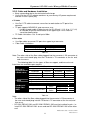
• Fiber Cable
⇒ Use fiber cable to connect FX port of an upper layer converter
⇒ Fiber Cable Limitations:
SC/ST/LC Converter Models
Multi-mode Full-duplex
220m
Single-mode Full-duplex
10/30/50Km
Table 2-1
Note: The other side of the fiber cable plugged into the converter’s RX connector at
the near end should plug into the FX device’s TX connector at the far end,
and vice versa.
The following table lists the types of fiber we support, and those else not
listed here are available upon request.
Multi-mode Fiber Cable and Modal Bandwidth
Multi-mode
62.5/125µm
Multi-mode 50/125µm
IEEE 802.3z
Modal
Modal
Gigabit Ethernet
Distance
Distance
Bandwidth
Bandwidth
1000SX 850nm
160MHz-Km
* 220m
400MHz-Km
500m
200MHz-Km
275m
500MHz-Km
550m
RC-2201.ZSC.212.10/30/50Km
Single-mode Fiber 9/125µm
1000LX
Single-mode transceiver 1310nm 10Km
Single-mode transceiver 1550nm 30, 50Km
RC-2201.ZBS.621.202 Single-Mode TX(Transmit) 1310nm
1000Base-LX
*20Km
RX(Receive)
1550nm
Single Fiber
Single-Mode
TX(Transmit)
1550nm
WDM
RC-2201.ZBS.621.201
*20Km
RX(Receive)
1310nm
*: Default module
Table 2-2
Note:
• The other side of the fiber cable plugged into the converter’s RX connector at
the near end should plug into the FX device’s TX connector at the far end, and
vice versa.
• RC-2201.ZBS.621.201 and RC-2201.ZBS.621.202 must be installed in pairs, i.e.
install RC-2201.ZBS.621.201 at one end and RC-2201.ZBS.621.202 at the other
end.
Publication date: October, 2005
Revision 1.0
11
Signamax 065-1600 series managed media converter
2-2-3. Management Station Installation
Signamax 065-1600 series converter is equipped with the serial port (RS232), Ethernet 10/100/1000 TP port and Ethernet 1000FX port. The users can use
any port to access and set up system configuration of Signamax 065-1600 series
converter.
Section 2-2-3-1: Installing management station through Signamax 065-1600 series
converter’s
RS-232 port running Terminal utility.
Section 2-2-3-2: Installing management station through Signamax 065-1600 series
converter’s TP
port running Telnet or browser
software.
Section 2-2-3-3: Installing management station through Signamax 065-1600 series
converter’s
Fiber port running Telnet or browser
software via Central Site
Converter Chassis.
Signamax 065-1600 series converter, Telnet and browser stations must assign the
proper IP address, subnet mask and default Gateway accordingly.
Publication date: October, 2005
Revision 1.0
12
Signamax 065-1600 series Managed Media Converter
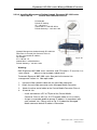
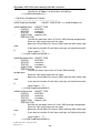
2-2-3-1. Installing Management Station through the Signamax 065-1600 series’
RS-232 Port
The serial port cable is attached directly to a DCE device through an RS-232
cable for console management.
5V DC Jack
RC-2201/02
Default IP Setting:
IP address = 192.168.1.1
Subnet Mask = 255.255.255.0
Default Gateway = 192.168.1.254
RS-232 cable with female
DB-9 connector at both ends
RS-232
Fig. 2-6
Terminal or Terminal Emulator
To connect the Managed Media Converter to the console user interface:
1. Locate the correct DB-9 serial port RS-232 cable with female DB-9
connector. Please refer to Appendix B for more details on Null Modem
Cable Specifications.
2. Attach the DB-9 female cable connector to the male DB-9 serial port
connector on the Managed Media Converter.
3. Attach the other end of the DB-9 serial port cable to an ASCII terminal
emulator. For example, Windows98/2000/XP HyperTerminal utility.
Signamax 065-1600 series converter uses the following serial port
parameter values:
Baud rate
Stop bits
Data bits
Parity
Flow control
57600
1
8
N
none
4. When the terminal emulator connected to Signamax 065-1600 series,
then press <Enter> key, the login prompt will be shown on the screen.
The default username and password are shown as below:
Username = admin
Password = admin
Publication date: October, 2005
Revision 1.0
13
Signamax 065-1600 series managed media converter
5. Please refer to Section 4-1 Console Management for details about
console user interface operating description.
Publication date: October, 2005
Revision 1.0
14
Signamax 065-1600 series Managed Media Converter
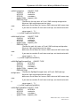
2-2-3-2. Installing Management Station through Signamax 065-1600 series TP
Port
RC-2201/02
Default IP Setting:
IP = 192.168.1.1
Subnet Mask = 255.255.255.0
Default Gateway = 192.168.1.254
Network Management Station through
Signamax 065-1600 series TP Port
Assign a reasonable IP address,
for example:
IP = 192.168.1.2
Subnet Mask = 255.255.255.0
Default Gateway = 192.168.1.254
Ethernet LAN
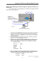
Fig. 2-7
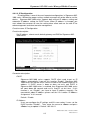
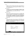
In Fig. 2-7, it is a simple example to show you the first step to connect to your PC
and the converter.
1. Attach Cat. 5 TP cable to connect PC and TP port of the Signamax 065-1600
series converter.
2. Boot up the converter.
3. Either run a terminal simulator and invoke a telnet session on PC, or run
browser software.
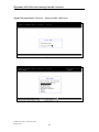
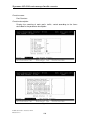
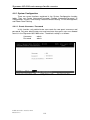
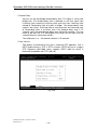
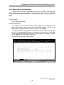
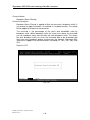
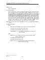
Right now, you can read the menu with text screen as Fig. 2-8. Input the default
username “admin” and the default password “admin”, and then you will read the
next page as Fig. 2-9.
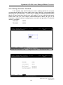
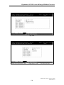
Use the <Up/Down> arrow keys to move the cursor to locate the entry of the
Configuration in the menu, and then press <Enter> key on the PC to select the item.
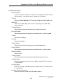
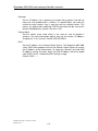
Now, the page for IP address configuration is shown and then also moves the
cursor to the entry of the IP Configuration, then press <Enter> key to select the item
you choose.
Publication date: October, 2005
Revision 1.0
15
Signamax 065-1600 series managed media converter
Gigabit Managed Media Converter – Signamax 065-1600 series
Fig. 2-8
Fig. 2-9
Publication date: October, 2005
Revision 1.0
16
Signamax 065-1600 series Managed Media Converter
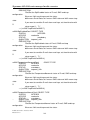
2-2-3-3. Installing Management Station through Signamax 065-1600 series
Fiber Port via
Central Site Converter Chassis
RC-2201/02
Default IP Setting:
IP = 192.168.1.1
Subnet Mask = 255.255.255.0
Default Gateway = 192.168.1.254
Network Management Station through RC-2201/02
Fiber Port via Central Site Converter Chassis
Assign a reasonable IP address,
for example:
IP = 192.168.1.2
Subnet Mask = 255.255.255.0
Default Gateway = 192.168.1.254
Fig. 2-10
Warning:
Both Signamax 065-1600 series converter and PC/station’s IP must be in a
same subnet,
please assign a proper subnet mask.
To connect Signamax 065-1600 series fiber port to the central site
management station via fiber optic cable:
1.
2.
3.
4.
Locate the fiber network cable with the male fiber connector.
Attach the male fiber connector to the Managed Media Converter.
Attach the other end of cable to the Central Media Converter Chassis.
At central site:
- Install and connect a PC to TP port of the Central Media
Converter Chassis with Cat. 5 UTP network cable (or via a switch).
- Assign a reasonable public or private IP address in accordance with
each network site. Please refer to Fig. 2-10 about the Managed
Media converter default IP address information.
Publication date: October, 2005
Revision 1.0
17
Signamax 065-1600 series managed media converter
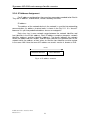
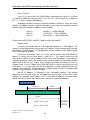
2-2-4. IP Address Assignment
For IP address configuration, there are four parameters needed to be filled in.
They are IP address, Subnet Mask, Default Gateway and DNS.
IP address:
The address of the network device in the network is used for internetworking
communication. Its address structure looks is shown in the Fig. 2-11. It is “classful”
because it is split into predefined address classes or categories.
Each class has its own network range between the network identifier and
host identifier in the 32 bits address. Each IP address comprises two parts: network
identifier (address) and host identifier (address). The former indicates the network
where the addressed host resides, and the latter indicates the individual host in the
network which the address of host refers to. And the host identifier must be unique
in the same LAN. Here the term of IP address we used is version 4, known as IPv4.
32 bits
Network identifier
Host identifier
Fig. 2-11 IP address structure
Publication date: October, 2005
Revision 1.0
18
Signamax 065-1600 series Managed Media Converter
With the classful addressing, it divides IP address into three classes, class A,
class B and class C. The rest of IP addresses are for multicast and broadcast. The
bit length of the network prefix is the same as that of the subnet mask and is
denoted as IP address/X, for example, 192.168.1.0/24. Each class has its address
range described below.
Class A:
Address is less than 126.255.255.255. There are a total of 126 networks can
be defined because the address 0.0.0.0 is reserved for default route and
127.0.0.0/8 is reserved for loopback function.
Bit #
0 1
78
31
0
Network address
Host address
Class B:
IP address range between 128.0.0.0 and 191.255.255.255. Each class B
network has a 16-bit network prefix followed 16-bit host address. There are 16,384
(2^14)/16 networks able to be defined with a maximum of 65534 (2^16 –2) hosts
per network.
Bit #
01 2
15 16
31
10
Network address
Host address
Class C:
IP address range between 192.0.0.0 and 223.255.255.255. Each class C
network has a 24-bit network prefix followed 8-bit host address. There are
2,097,152 (2^21)/24 networks able to be defined with a maximum of 254 (2^8 –2)
hosts per network.
Bit # 0 1 2 3
23 24
31
110
Network address
Host address
Publication date: October, 2005
Revision 1.0
19
Signamax 065-1600 series managed media converter
Class D and E:
Class D is a class with first 4 MSB (Most significance bit) set to 1-1-1-0 and
is used for IP Multicast. See also RFC 1112. Class E is a class with first 4 MSB set
to 1-1-1-1 and is used for IP broadcast.
According to IANA (Internet Assigned Numbers Authority), there are three
specific IP address blocks reserved and able to be used for extending internal
network. We call it Private IP address and list below:
Class A
Class B
Class C
10.0.0.0 --- 10.255.255.255
172.16.0.0 --- 172.31.255.255
192.168.0.0 --- 192.168.255.255
Please refer to RFC 1597 and RFC 1466 for more information.
Subnet mask:
It means the sub-division of a class-based network or a CIDR block. The
subnet is used to determine how to split an IP address to the network prefix and the
host address in bitwise basis. It is designed to utilize IP address more efficiently and
ease to manage IP network.
For a class B network, 128.1.2.3, it may have a subnet mask 255.255.0.0 in
default, in which the first two bytes is with all 1s. This means more than 60
thousands of nodes in flat IP address will be at the same network. It’s too large to
manage practically. Now if we divide it into smaller network by extending network
prefix from 16 bits to, say 24 bits, that’s using its third byte to subnet this class B
network. Now it has a subnet mask 255.255.255.0, in which each bit of the first
three bytes is 1. It’s now clear that the first two bytes is used to identify the class B
network, the third byte is used to identify the subnet within this class B network and,
of course, the last byte is the host number.
Not all IP address is available in the sub-netted network. Two special
addresses are reserved. They are the addresses with all zero’s and all one’s host
number. For example, an IP address 128.1.2.128, what IP address reserved will be
looked like? All 0s mean the network itself, and all 1s mean IP broadcast.
128.1.2.128/25
Network
Subnet
10000000.00000001.00000010.1 0000000
25 bits
All 0s = 128.1.2.128
All 1s= 128.1.2.255
Publication date: October, 2005
Revision 1.0
20
1 0000000
1 1111111
Signamax 065-1600 series Managed Media Converter
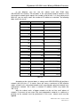
In this diagram, you can see the subnet mask with 25-bit long,
255.255.255.128, contains 126 members in the sub-netted network. Another is that
the length of network prefix equals the number of the bit with 1s in that subnet mask.
With this, you can easily count the number of IP addresses matched. The following
table shows the result.
Prefix Length No. of IP matched No. of Addressable IP
/32
1
-
/31
2
-
/30
4
2
/29
8
6
/28
16
14
/27
32
30
/26
64
62
/25
128
126
/24
256
254
/23
512
510
/22
1024
1022
/21
2048
2046
/20
4096
4094
/19
8192
8190
/18
16384
16382
/17
32768
32766
/16
65536
65534
Table 2-3
According to the scheme above, a subnet mask 255.255.255.0 will partition a
network with the class C. It means there will have a maximum of 254 effective
nodes existed in this sub-netted network and is considered a physical network in an
autonomous network. So it owns a network IP address which may looks like
168.1.2.0.
With the subnet mask, a bigger network can be cut into small pieces of
network. If we want to have more than two independent networks in a worknet, a
partition to the network must be performed. In this case, subnet mask must be
applied.
Publication date: October, 2005
Revision 1.0
21
Signamax 065-1600 series managed media converter
For different network applications, the subnet mask may look like
255.255.255.240. This means it is a small network accommodating a maximum of
15 nodes in the network.
Default gateway:
For the routed packet, if the destination is not in the routing table, all the
traffic is put into the device with the designated IP address, known as default router.
Basically, it is a routing policy.
For assigning an IP address to Signamax 065-1600 series, you just have to
check what the IP address of the network will be connected using the Signamax
065-1600 series converter. Use the same network address and append your host
address to it.
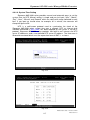
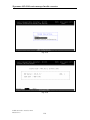
Fig. 2-12
First, IP Address: as shown in the Fig. 2-12, enter “192.168.1.1”, for instance.
For sure, an IP address such as 192.168.1.x must be set on your PC.
Second, Subnet Mask: as shown in the Fig. 2-12, enter “255.255.255.0”. Any
subnet mask such as 255.255.255.x is allowable in this case.
DNS:
The Domain Name Server translates human readable machine name to IP
address. Every machine on the Internet has a unique IP address. A server generally
has a static IP address. To connect to a server, the client needs to know the IP of
the server. However, user generally uses the name to connect to the server. Thus,
the RC-2201 DNS client program (such as a browser) will ask the DNS to resolve
the IP address of the named server.
Publication date: October, 2005
Revision 1.0
22
Signamax 065-1600 series Managed Media Converter
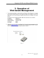
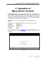
3. Operation of
Web-based Management
1. The converter provides a web function by Ethernet Port (Browser) to manage
and monitor the port activity. If you need to change the IP address at the first
time, you can use the console to modify and also refer to Chapter 4 for more
details.
The default values of Signamax 065-1600 series converter are as follows:
IP Address
:192.168.1.1
Subnet Mask
:255.255.255.0
Default Gateway
:192.168.1.254
Username
:admin
Password
:admin
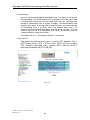
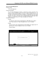
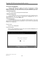
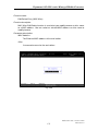
2. After the converter had been configured via the console, you can browse it. For
instance, http://192.168.1.1, then enter the username and password as above.
Both of the default username and password are “admin”.
Fig. 3-1
Publication date: October, 2005
Revision 1.0
23
Signamax 065-1600 series managed media converter
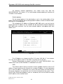
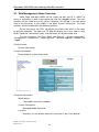
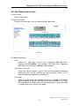
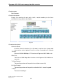
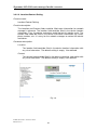
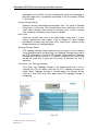
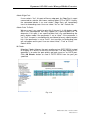
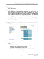
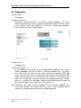
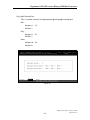
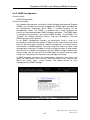
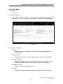
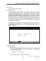
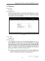
3-1. Web Management Home Overview
Home Page and Main MENU will be shown up after you fill in “admin” to
serve as username as well as password and click the <Login> button. The main
functions will be listed on the left side of a browser. On the top is the front panel
view of the converter. In the middle is the basic System Information. The main
functions will be introduced in the following sections.
On the front panel, the LEDs will display the status color which is the same
as physical hardware. The fiber and TP plug will display the status color as well.
Green stands for “connected” status and red stands for “disconnected” one.
The main functions are “Port Status and Counter”, “System Information”,
“Configuration”, “Diagnostics”, “Show Log Data”, “Software Upgrade”, “Reboot” and
“Logout”.
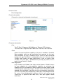
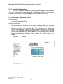
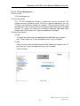
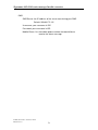
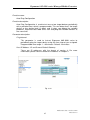
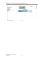
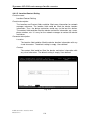
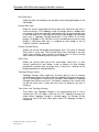
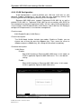
Function name:
System Information
Function description:
Show the basic system information.
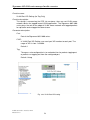
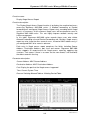
Fig. 3-2
Parameter description:
Model Name:
The model name of this product.
System Description:
Managed Media Converter
Location:
Basically, it is the location where this converter is put. User-defined.
Publication date: October, 2005
Revision 1.0
24
Signamax 065-1600 series Managed Media Converter
Contact:
Basically, it is the contact window in charge of the maintenance of this
converter. User-defined.
System Up Time:
The time accumulated since this converter is powered up. Its format is
day, hour, minute, second.
Current Time:
Shows the system time of the Signamax 065-1600 series converter. Its
format: day of week, month, day, hours : minutes : seconds, year. For
instance, Wed, Apr. 06, 12:10:10, 2004.
IP Address:
The IP address that indicates where Signamax 065-1600 series is
located (e.g. default IP address of Signamax 065-1600 series is
192.168.1.1).
MAC Address:
It is the MAC address of the management agent in this converter.
BIOS Version:
The version of the BIOS in this converter.
Firmware Version:
The firmware version used in this converter.
Hardware-Mechanical Version:
The Hardware and Mechanical version of the converter. The figure
before the hyphen is the version of electronic hardware; the one after the
hyphen is the version of mechanical.
RAM Size:
The size of the DRAM in this converter.
Flash Size:
The size of the flash memory in this converter.
System Temperature:
The air temperature inside of this converter.
Series Number:
The serial number is assigned by manufacturer.
Device Port:
Show all types and numbers of the port. In Signamax 065-1600 series,
there are one serial port, one TP port and one FX port.
Publication date: October, 2005
Revision 1.0
25
Signamax 065-1600 series managed media converter
Fiber Port:
Show the connector type (e.g. SC/LC), fiber mode (e.g. Single/Multi
mode) status and number of fiber port.
Case Detection:
Show the status of the upper case of this converter. When the case is lid
off, it shows “Open”; otherwise, it shows “Close”.
Publication date: October, 2005
Revision 1.0
26
Signamax 065-1600 series Managed Media Converter
3-2. The Function Tree in Web Management
For offering you a clear guide to use this Managed Media Converter, the
following is the whole function tree of Signamax 065-1600 series in web
management. User can refer to the following sections based on the order of this
function tree below for more details.
Port Status and Counter
Port Current Status
Port Counters
Port Configuration
System Information
Configuration
System Configuration
Username/Password Setting
IP Configuration
System Time Setting
Location/Contact Setting
TP Port Management
Power Down Setting
Network Management
SNMP Configuration
Max. Packet Length Setting
Broadcasting Suppression
Misc. Feature Configuration
Spanning Tree Configuration
Filtering Configuration
VLAN Configuration
Trap/Alarm Configuration
Trap Events Configuration
Alarm Configuration
Save Configuration
Save As User Configuration
Restore Default Configuration
Restore User Configuration
Publication date: October, 2005
Revision 1.0
27
Signamax 065-1600 series managed media converter
Diagnostics
Diagnostics
Loopback Test
Ping Test
Auto Ping Configuration
Show Log Data
Trap Log Data
Illegal Access Report Config.
Illegal Access Report Status
Illegal Access Report
Mac Alias
Software Upgrade
Reboot
Logout
Publication date: October, 2005
Revision 1.0
28
Signamax 065-1600 series Managed Media Converter
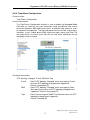
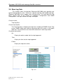
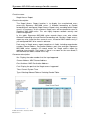
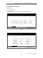
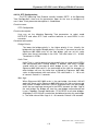
3-3. Port Status and Counter
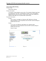
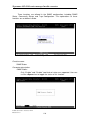
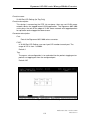
Function name:
Port Current Status
Function description:
Display the current port status of Signamax 065-1600 series.
Fig. 3-3
Parameter description:
Port:
Display TP / Fiber port. The TP Port is Signamax 065-1600 series’
Ethernet 10/100/1000Mbps UTP interface. The Fiber Port is Signamax
065-1600 series’ Ethernet 1000Mbps Fiber interface.
Link Status: UP, Down
Show if the link on the port is active. If the link is connected to a working
well device, the Link will show the link “Up”, otherwise, “Down”. This is
determined by the negotiation of hardware.
Port State:
Show if the communication capability of the port is Enabled or Disabled.
When enabled, traffic can be transmitted and received via this port.
When disabled, no traffic can be transferred through this port. Port State
is configured by user. Default is Enabled.
Publication date: October, 2005
Revision 1.0
29
Signamax 065-1600 series managed media converter
Auto Negotiation:
Show the exchange mode of Ethernet MAC. There are two modes
supported in Signamax 065-1600 series. They are auto-negotiation mode
“Enabled” and forced mode “Disabled”. When in “Enabled” mode, this
function will automatically negotiate by hardware itself and exchange
each other the capability of speed and duplex mode with other site which
is linked, and come out the best communication way. When in “Disabled”
mode, both parties must have the same setting of speed and duplex,
otherwise, both will not be linked. In this case, the link result is “Down”.
Default: TP port is Enabled mode, Fiber port is Disabled mode.
Speed/Duplex:
Display the speed and duplex of all port. There are two speeds 10Mbps
and 100Mbps supported in Signamax 065-1600 series. The duplex
supported is half duplex and full duplex. The status of speed/duplex
mode is determined by 1) the negotiation of both local port and link
partner in “Enabled” mode or 2) user setting in “Disabled” mode. The
local port has to be preset its capability.
In TP port is supported Fast Ethernet with TP media, so the result will
show 100Mbps/full duplex, 100Mbps/half duplex, 10Mbps/Full duplex
and 10Mbps/half duplex.
In Fiber port is supported Fast Ethernet with Fiber media, so the result
will show 100Mbps/full duplex or 100Mbps/half duplex.
Default: TP port: None, depends on the result of the negotiation
Fiber port: 100Mbps/Full duplex
Flow Control: Enabled, Disabled
Show each port’s flow control status. There are two types of flow control
in Ethernet, Backpressure for half-duplex operation and Pause flow
control (IEEE802.3x) for full-duplex operation. Signamax 065-1600
series supports both of them. When duplex mode is half duplex, there is
only one status “Enabled” for flow control. When in full duplex, it may be
one of “Enabled”, or “Disabled”. Default: Enabled
Media Type: UTP Cable, Fiber Cable
Only “Fiber Cable” and “UTP Cable” are in this model.
Connector:
Display the connector type, for instance, UTP, SC, ST, LC, and so on.
Fiber Mode:
Display the fiber mode, for instance, Multi-Mode, Single-Mode.
Fiber Cable:
Display the cable type, for instance, Dual Wire, Single Wire.
Publication date: October, 2005
Revision 1.0
30
Signamax 065-1600 series Managed Media Converter
Wavelength:
Display the wavelength of the light transmitted in the fiber, for instance,
1310nm, 1550nm.
Max. Distance:
Display the maximum distance the port supported, for instance, 100m,
20km, 40km and so on.
Speed:
Display the maximum speed of the port, for instance, “1G”, “100M”.
Publication date: October, 2005
Revision 1.0
31
Signamax 065-1600 series managed media converter
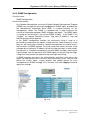
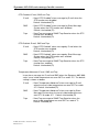
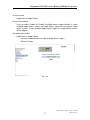
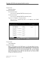
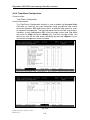
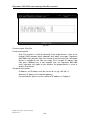
Function name:
Port Counters
Function description:
Display the counting of each port’s traffic, sorted according to the items
described in the parameter description.
Fig. 3-4
Parameter description:
Refresh Interval:
A Refresh Interval selection list on the web is used to set or change web
view counters refresh period. It can be set from 3 seconds to 10 seconds.
TP Port:
Ethernet 10/100/1000Mbps UTP interface of Signamax 065-1600 series.
Fiber Port:
The Ethernet 1000 Mbps fiber interface of the Signamax 065-1600 series
converter.
Tx Good Packet:
The counting number of the packet transmitted successfully.
Rx Good Packet:
The counting number of the packet received which is treated as good.
Tx Byte:
Total transmitted bytes.
Publication date: October, 2005
Revision 1.0
32
Signamax 065-1600 series Managed Media Converter
Rx Byte:
Total received bytes.
Tx Bad Packet:
The counting number of the packet transmitted abnormally.
Rx Bad Packet:
The counting number of the packet received which is treated as bad.
Collision Counter:
Collision times.
Tx Abort Packet:
The counting number of the packet aborted during transmission.
Tx Speed (bps):
Show the average transmission rate in bit per second. The time interval
is user-defined.
Rx Speed (bps):
Show the average received data rate in bit per second. The time interval
is user-defined.
Broadcast Packets:
Show the counting number of the broadcast packet.
CRC/Alignment Errors:
Show the counting number of the packet with CRC and Alignment error.
Undersize Packets:
Show the counting number of the packet with the length less than 64
bytes.
Oversize Packets:
Show the counting number of the packet with the length more than
1522/1536 bytes depend on maximum packet length setting.
64 byte Packets Received:
Show the counting number of the packet with exact 64 bytes length.
65-127 byte Packets Received:
Show the counting number of the packet with the length between 65 to
127 bytes.
128-255 byte Packets Received:
Show the counting number of the packet with the length between 128 to
255 bytes.
Publication date: October, 2005
Revision 1.0
33
Signamax 065-1600 series managed media converter
256-511 byte Packets Received:
Show the counting number of the packet with the length between 256 to
511 bytes.
512-1023 byte Packets Received:
Show the counting number of the packet with the length between 512 to
1023 bytes.
1.0-1.5 Kbytes Packets Received:
Show the counting number of the packet with the length between 1024 to
1536 bytes.
Unicast Packets Transmitted:
Show the counting number of total unicast packets transmitted.
NonUnicast Packets Transmitted:
Show the counting number of both total multicast and broadcast packets
transmitted.
Publication date: October, 2005
Revision 1.0
34
Signamax 065-1600 series Managed Media Converter
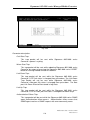
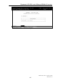
Function name:
Port Configuration
Function description:
Change the state and configuration of each port.
Fig. 3-5
Parameter description:
Port:
The TP Port is Signamax 065-1600 series’ Ethernet UTP interface.
The Fiber Port is Signamax 065-1600 series’ Ethernet Fiber interface.
State:
Show if the communication capability of the port is Enabled or Disabled.
When enabled, traffic can be transmitted and received via this port.
When disabled, the port is blocked and no traffic can be transferred
through this port. Port State is configured by the user. Only two states
“Enable” and “Disable” are able to be chosen. If you set a port’s state
“Disable”, then that port is prohibited from passing any traffic, even it
looks Link up. Default is Enable.
Auto Negotiation:
Only “Enable” and “Disable” two states can be chosen. “Enable” means
the port adopted the auto-negotiation algorithm to exchange the
capability with the linked partner. When enabled, the speed, duplex mode
and flow control mode may change. “Disable” means the forced mode is
adopted. When disabled, if you want to set up a connection successfully,
you must have both port configuration of local port and linked partner be
the same. If their configuration is different, the link will not be set up
successfully. In Signamax 065-1600 series, fiber port supports forced
mode only.
Publication date: October, 2005
Revision 1.0
35
Signamax 065-1600 series managed media converter
Speed/Duplex:
Set the mode of speed and duplex. In speed, 10/100/1000Mbps baud
rate is available for Fast Ethernet TP port. The Fiber port is available in
speed 1000Mbps only. If the media is 1Gbps fiber, it is always 1000Mbps
and the duplex is full only. If the media is TP, the Speed/Duplex is
comprised of the combination of speed mode, 10/100/1000Mbps, and
duplex mode, full duplex and half duplex.
Flow Control:
There are three modes to choose in flow control, including Asymmetric,
Symmetric and Disable. If Symmetric flow control is set, both parties can
send PAUSE frame to the transmitting device(s) if the receiving port is
too busy to handle. If Asymmetric flow control is set, this will let the
receiving port not care the PAUSE frame from transmitting device(s).
This is one-way flow control. When it is set Disable, there will be no flow
control in the port. It drops the packet if too much to handle.
Default: Symmetric in full-duplex mode and Backpressure in half duplex.
Publication date: October, 2005
Revision 1.0
36
Signamax 065-1600 series Managed Media Converter
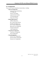
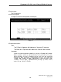
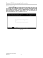
3-4. Configuration
There are four major configuration function folders, including:
System Configuration
Username / Password Setting
IP Configuration
System Time Setting
Location/Contact Setting
TP Port Management
Power Down Setting
Network Management
SNMP Configuration
Max. Packet Length Setting
Broadcasting Suppression
Misc. Feature Configuration
Spanning Tree Configuration
Filtering Configuration
VLAN Configuration
Trap/Alarm Configuration
Trap Events Configuration
Alarm Configuration
Save Configuration
Save As User Configuration
Restore Default Configuration
Restore User Configuration
Publication date: October, 2005
Revision 1.0
37
Signamax 065-1600 series managed media converter
3-4-1. System Configuration
There are six functions contained in the System Configuration function folder.
They are Username/Password Setting, IP Configuration, System Time Setting,
Location/Contact Setting, TP Port Management and Power Down Setting.
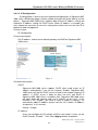
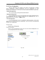
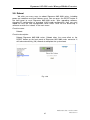
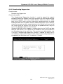
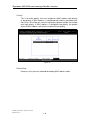
3-4-1-1. Username / Password Setting
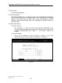
Function name:
Username/Password Setting
Function description:
In this function, only administrator can create, modify or delete the username
and password. Administrator can modify other guest identities’ password
without confirming the password but it is necessary to modify the
administrator-equivalent identity. A guest-equivalent identity can only modify
his or her individual password. Please note that you must confirm
administrator/guest identity by pulling down the list of Authorization in advance
before configuring the username and password. The default setting is as
follows:
Username
Password
: admin
: admin
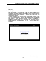
Fig. 3-6
Publication date: October, 2005
Revision 1.0
38
Signamax 065-1600 series Managed Media Converter
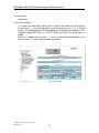
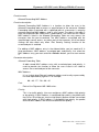
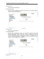
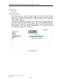
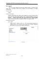
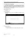
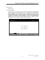
3-4-1-2. IP Configuration
IP configuration is one of the most important configurations in Signamax 0651600 series. Without the proper setting, network manager will not be able to see the
device. Signamax 065-1600 series supports both manual IP address setting and
automatic IP address setting via DHCP server. When IP address is changed, you
must reboot the converter to have the setting taken effect and use the new IP to
browse for web management.
Function name:
IP Configuration
Function description:
Set IP address, subnet mask, default gateway and DNS for Signamax 0651600 series.
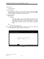
Fig. 3-7
Parameter description:
DHCP:
Signamax 065-1600 series supports DHCP client used to get an IP
address automatically if you set this function “Enable”. Signamax 0651600 series will find the DHCP server existed in the network to get an IP
address. If DHCP server is down or does not exist and DHCP in
Signamax 065-1600 series is enabled, then Signamax 065-1600 series
will count down 60 seconds and use its fixed IP set last time. If this
function is set “Disable”, you have to input IP address manually. For
more details about IP address, please see the 2-2-4 section “IP Address
Assignment” in this manual.
Default: Disable
IP address:
Users can configure the IP settings and fill in new values if users set the
DHCP function “Disable”. Then, click <Apply> button to update it.
Publication date: October, 2005
Revision 1.0
39
Signamax 065-1600 series managed media converter
Default: 192.168.1.1
Publication date: October, 2005
Revision 1.0
40
Signamax 065-1600 series Managed Media Converter
Subnet mask:
Set the subnet mask value which is the same as that of network it
attaches. For more information, please also see the section “IP Address
Assignment” in this manual.
Default: 255.255.255.0
Default gateway:
Set an IP address for a gateway to handle those packets that do not
meet the rules predefined in a device. If a packet does not meet the
criteria for other routers, then it must be sent to a default router. This
means any packet with undefined TCP/IP information will be sent to this
device unconditionally.
Default: 192.168.1.254
DNS:
Set an IP address for a Domain Name Server. The Signamax 065-1600
series DNS client program will ask the Domain Name Server to resolve
the IP address of the named host. To select the “Manual” for fixed DNS
IP address setting. To select “Auto” the DNS IP address will be assigned
from DHCP server. The default DNS setting is empty.
Default: DNS : -----
Publication date: October, 2005
Revision 1.0
41
Signamax 065-1600 series managed media converter
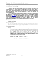
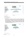
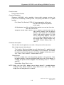
3-4-1-3. System Time Setting
Signamax 065-1600 series provides manual and automatic ways to set the
system time via NTP. Manual setting is simple and you just input “Year”, “Month”,
“Day”, “Hour”, “Minute” and “Second” within the valid value range indicated in each
item. If you input an invalid value, for example, 61 in minute, the converter will
clamp the figure to 59.
NTP is a well-known protocol used to synchronize the clock of the Signamax
065-1600 series system time over a network. NTP, an internet draft standard
formalized in RFC 1305, has been adopted on the system is version 3 protocol.
Signamax 065-1600 series provides four built-in NTP server IP addresses resided
in the Internet and a user-defined NTP server IP address. The time zone is
Greenwich-centered which uses the expression form of GMT+/- xx hours.
Function name:
System Time Setting
Function description:
Set the system time by manual input or set it by syncing from Time servers.
The function also supports daylight saving for different area’s time adjustment.
Parameter description:
Manual:
This is the function to adjust the time manually. Filling the valid figures in
the fields of Year, Month, Day, Hour, Minute and Second respectively and
press <Apply> button, time is adjusted. The valid figures for the
parameter Year, Month, Day, Hour, Minute and Second are >=2000, 1-12,
1-31, 0-23, 0-59 and 0-59 respectively. Input the wrong figure and press
<Apply> button, the device will reject the time adjustment request. There
is no time zone setting in Manual mode.
Default: Year = 2000,
Hour = 0,
Month = 1,
Day = 1
Minute = 0,
Second = 0
Publication date: October, 2005
Revision 1.0
42
Signamax 065-1600 series Managed Media Converter
NTP:
NTP is Network Time Protocol and is used to sync the network time
based Greenwich Mean Time (GMT). If use the NTP mode and select a
built-in NTP time server or manually specify an user-defined NTP server
as well as Time Zone, Signamax 065-1600 series will sync the time in a
short after pressing <Apply> button. Though it synchronizes the time
automatically, NTP does not update the time periodically without user’s
processing.
Time Zone is an offset time off GMT. You have to select the time zone
first and then perform time sync via NTP because Signamax 065-1600
series will combine this time zone offset and updated NTP time to come
out the local time, otherwise, you will not able to get the correct time.
Signamax 065-1600 series supports configurable time zone from –12 to
+13 in 1 hour steps.
Default Time zone: +8 Hrs.
Daylight Saving:
Daylight saving is adopted in some countries. If set, it will adjust the time
lag or in advance in unit of hours, according to the starting date and the
ending date. For example, if you set the day light saving to be 1 hour.
When the time passes over the starting time, the system time will be
increased one hour after one minute at the time since it passed over. And
when the time passes over the ending time, the system time will be
decreased one hour after one minute at the time since it passed over.
Signamax 065-1600 series supports valid configurable day light saving
time is –5 ~ +5 step one hour. The zero for this parameter means it need
not have to adjust current time, equivalent to in-act daylight saving. You
don’t have to set the starting/ending date as well. If you set daylight
saving to be non-zero, you have to set the starting/ending date as well;
otherwise, the daylight saving function will not be activated.
Default for Daylight Saving: 0.
The following parameters are configurable for the function Daylight
Saving and described in detail.
Day Light Saving Start :
This is used to set when to start performing the daylight saving time.
Mth:
Range is 1 ~ 12.
Default: 1
Day:
Range is 1 ~ 31.
Default: 1
Hour:
Publication date: October, 2005
Revision 1.0
43
Signamax 065-1600 series managed media converter
Range is 0 ~ 23.
Default: 0
Publication date: October, 2005
Revision 1.0
44
Signamax 065-1600 series Managed Media Converter
Day Light Saving End :
This is used to set when to stop performing the daylight saving time.
Mth:
Range is 1 ~ 12.
Default: 1
Day:
Range is 1 ~ 31.
Default: 1
Hour:
Range is 0 ~ 23.
Default: 0
Fig. 3-8
Publication date: October, 2005
Revision 1.0
45
Signamax 065-1600 series managed media converter
3-4-1-4. Location/Contact Setting
Function name:
Location/Contact Setting
Function description:
The Location and Contact fields could be filled some information for network
manager’s reference. The location field could be filled in the device location
information. Thus, the device maintainer could find out this device easily. The
contact field could be filled in the device maintainer information e.g. name,
phone number, etc. It is easy for the network manager to contact the device
maintainer.
Parameter description:
Location:
The location field could be filled in the device location information with
any visual characters. The default setting is empty. User-defined.
Contact:
The contact field could be filled in the device maintainer information with
any visual characters. The default setting is empty. User-defined.
Fig. 3-9
Publication date: October, 2005
Revision 1.0
46
Signamax 065-1600 series Managed Media Converter
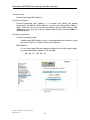
3-4-1-5. TP Port Management
Function name:
TP Port Management
Function description:
This TP Port Management design is concerning security enhanced. This
remote converter should be put on CPE site in general application, thus the
TP port is connected to network of customer. There are many attack issue
possible enter from TP port to effect the Signamax 065-1600 series managed
function. To isolate the traffics with managed Signamax 065-1600 series
request from TP port when the TP port management is disabled.
Parameter description:
Disable:
To isolate the traffics with managed Signamax 065-1600 series request
from TP port when the TP port management was set to “Disabled”.
Enable:
Allow the traffics with managed Signamax 065-1600 series request from TP
port when the TP port management was set to “Enabled”.
Default: Enable
Fig. 3-10
Publication date: October, 2005
Revision 1.0
47
Signamax 065-1600 series managed media converter
3-4-1-6. Power Down Setting
Function name:
Power Down Setting
Function description:
This design is concerning for system safety. This function will detect two things:
o
the temperature if over 60 C, the cooling fan if failed. If these two conditions
happened at the same time and the “Power Down Setting” was enabled, the
Signamax 065-1600 series will power down automatically.
Parameter description:
Disable:
If this function is disabled, the Signamax 065-1600 series will keep
o
working regardless of the temperature was over 60 C and the cooling fan
failed at the same time.
Enable:
In this status, the Signamax 065-1600 series will power down
o
automatically while the temperature was over 60 C and the cooling fan
failed at the same time.
Default: Enable
Fig. 3-11
Publication date: October, 2005
Revision 1.0
48
Signamax 065-1600 series Managed Media Converter
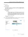
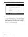
3-4-2. SNMP Configuration
Function name:
SNMP Configuration
Function description:
Any Network Management running the Simple Network Management Protocol
(SNMP) can manage the converter equipped with SNMP agent, provided that
the Management Information Base (MIB) is installed correctly on the
management station. The SNMP is a protocol that is used to govern the
transfer of information between SNMP manager and agent. The SNMP agent
is running on the converter if you set the SNMP “Enable”. If the SNMP is set
“Disable”, the related Community Name, Trap Host IP Address, Trap and
RMON counters will be ignored.
In the SNMP Configuration function, the community string is used as a
password to authenticate the request. If both have the same community name,
they can talk each other; otherwise, network management unit cannot access
the converter via SNMP protocol. To set up a trap host means to create a trap
manager by assigning an IP address to host the trap message. In other words,
the trap host is a network management unit with SNMP manager receiving the
trap message from the converter with SNMP agent issuing the trap message.
4 trap hosts can prevent the important trap message from losing.
A SNMP manager must pass the authentication, and then it can access the
agent. So, both parties must have the same community name. You can also
define the system name, system location and contact person for easy
management via SNMP manager. Fill in the data, then click <Apply> button to
apply new settings.
Fig. 3-12
Publication date: October, 2005
Revision 1.0
49
Signamax 065-1600 series managed media converter
Parameter description:
SNMP
SNMP enable/disable selection. Default is “Enable”.
Get Community:
User-definable community name for the authentication of SNMP Get
community, the default is “public”.
Set Community:
User-definable community name for the authentication of SNMP Set
community, the default is “private”.
Trap Host 1 IP Address:
To set up a trap host IP address in order to receive Signamax 065-1600
series’ trap message. The default host 1 IP address “0.0.0.0” means that
the transmission of trap message to host 1 is disabled.
Community: (Host 1)
User-definable community name for the authentication of SNMP Trap
community for host 1, the default is “public”.
Trap Host 2 IP Address:
This parameter setting is the same as “Trap Host 1 IP Address”.
Community: (Host 2)
This parameter setting is the same as “Community (Host 1)”. The default
is “public”.
Trap Host 3 IP Address:
This parameter setting is the same as “Trap Host 1 IP Address”.
Community: (Host 3)
This parameter setting is the same as “Community (Host 1)”. The default
is “public”.
Trap Host 4 IP Address:
This parameter setting is the same as “Trap Host 1 IP Address”.
Community: (Host 4)
This parameter setting is the same as “Community (Host 1)”. The default
is “public”.
Publication date: October, 2005
Revision 1.0
50
Signamax 065-1600 series Managed Media Converter
Cold Start Trap:
This trap packet will be sent while Signamax 065-1600 series
Converter’s power is cycling.
Warm Start Trap:
This trap packet will be sent while rebooting Signamax 065-1600 series
Converter by means of pressing the Signamax 065-1600 series’ RESET
button or running Reboot function of software.
Link Down Trap:
This trap packet will be sent while the Signamax 065-1600 series
Converter’s UTP link status is changed from up to down. The Link Down
Trap Packet will not be sent while Signamax 065-1600 series
Converter’s fiber port link status is changed from up to down. The fiber
port Link Down Event will be stored in Log Data.
Link Up Trap:
This trap packet will be sent while the Signamax 065-1600 series
Converter’s UTP or Fiber port link status is changed from down to up.
Authentication Failure Trap:
This trap packet will be sent while the Signamax 065-1600 series SNMP
agent authentication failure occurs. Authentication failure means that
SNMP agent receives a SNMP request with error community name.
Publication date: October, 2005
Revision 1.0
51
Signamax 065-1600 series managed media converter
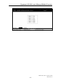
3-4-3. Max. Packet Length Setting
Signamax 065-1600 series provides two levels of Ethernet frame size for the
user to set up. One is 1536 bytes and the other is 1522 bytes. After selecting one of
these two options and then pressing <Apply> button, the setting will take effect
immediately. Default setting is 1522 bytes long which can afford accommodating the
size of the tagged VLAN frame.
Fig. 3-13
Publication date: October, 2005
Revision 1.0
52
Signamax 065-1600 series Managed Media Converter
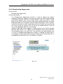
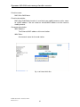
3-4-4. Broadcasting Suppression
Function name:
Broadcasting Suppression
Function description:
The Broadcasting Suppression function is used to spread the request
broadcast packet into a bigger time frame to prevent the traffic congestion due
to broadcast packets from many network devices which may seek its NMS,
boot server, DHCP server and many connections predefined when the whole
building or block loses the power and then reboot and recover. At this moment,
a bunch of converter or other network device on the LAN will try its best to find
the server to get the services or try to set up the predefined links, they will
issue many broadcast packets in the network.
Signamax 065-1600 series supports a random delay time for DHCP and boot
delay for each device. This suppresses the broadcast storm while all devices
are at booting stage in the same time. The maximum user-defined delay time
is 30 sec. If Broadcasting Suppression function is enabled, the delay time is
set randomly, ranging from 0 to 30 seconds, because the exactly delay time is
computed by the converter itself. The default is “Disable”.
Fig. 3-14
Publication date: October, 2005
Revision 1.0
53
Signamax 065-1600 series managed media converter
3-4-5. Misc. Feature Configuration
Miscellaneous Feature Configuration gathers many functions, including MAC
Address Aging Time Setting, Broadcast Storm Filter Limit, Priority Queue Service,
Max. bridge transmit delay bound control and QoS Policy in a page, which cannot
be categorized to some function type. They are described below.
Function Name:
MAC Address Aging Time Setting
Function Description:
This function is used to set the MAC Address Age-out Time applied to the
whole MAC address table except some static MAC address. The range of
MAC table address entry age-out time is from 30, 33, 36,…765 seconds.
If a source node has not visited the converter for a time longer than the Ageout Time, its responded MAC address information in the converter’s MAC table
will be marked invalid by the converter’s aging function. This age-out rule will
not be applied to the static MAC addresses.
The default age-out time is 300 seconds.
Function Name:
Broadcast Storm Filter Limit
Function Description:
Broadcast Storm Filter Limit is applied to filter the converter’s broadcast traffic.
If you choose an upper threshold, it is enabled. It is a global function. The
setting will be applied to all ports of the converter.
The threshold is the percentage of the port's total bandwidth used by
broadcast traffic. When broadcast traffic for a port rises above the threshold
you set, broadcast storm filter discards the extra broadcast traffic. This keeps
the total broadcast traffic less than the threshold able to be forwarded and
limits too many broadcast packet running over the network. Signamax 0651600 series supports five threshold values, including 5%, 10%, 15%, 20%, and
25%.
Default is OFF.
Publication date: October, 2005
Revision 1.0
54
Signamax 065-1600 series Managed Media Converter
Function name:
Priority Queue Service
Function Description:
Signamax 065-1600 series provides three priority queue services for
transmission scheduling, including FCFS, strict priority and WRR. It is a global
function.
First Come First Service (FCFS): All incoming packets will be sent out
upon the sequence of packet’s
arrival order.
All High before Low: After all high priority packets are sent out, and then
low
ones are sent
in turn.
Weighted Round Robin (WRR): This is actually a transmission ratio of
high priority packet and low priority
packet. If you would like to repeatedly
send 5 high priority packets first and
then 2 low priority packets. You can
set a 5 to high weight field and a 2 to
low weight field in WRR function row.
The WRR Default Setting High = 2,
Low = 1
Function name:
Max. bridge transmit delay bound control
Function description:
To set the time that the packets can reside in the queue of the converter.
Parameter description:
Max. bridge transmit delay bound control:
The function “Maximum bridge transmit delay bound control” is applied to
limit the maximum queuing time of the packets in the converter. If
enabled, the packets queued over the time set will be dropped. Valid
values are 1 sec., 2 sec., 4 sec. and OFF. Default value is OFF.
Enable Delay Bound:
Limit the resided time of the low priority packets in the converter. If the
low priority packet is not transmitted out and time set by “Delay bound” is
enabled, the packet will be dropped. The valid delay time is 1 – 255 ms
and OFF. Default Max. Delay Time is 1ms.
NOTE: Make sure that “Max. bridge transmit delay bound control” is enabled
before enabling Delay Bound, because Enable Delay Bound must
work under “Max. bridge transmit delay bound control is enabled”.
Publication date: October, 2005
Revision 1.0
55
Signamax 065-1600 series managed media converter
Function name:
QoS Policy
Function Description:
It is used to assign which priority level is high or low. Normally, we map the
priority levels 7 – 4 to be high priority and the priority levels 3 – 0 to be low
priority. The mapped priority will be applied to the forwarding scheduler. In the
Signamax 065-1600 series, it is FCFS, Strict and WRR. The QoS policy is
global.
Default: If enabled, priority levels 7 – 4 are assigned to be high priority, and
priority levels 3 – 0 are assigned to be low priority.
Fig. 3-15
Publication date: October, 2005
Revision 1.0
56
Signamax 065-1600 series Managed Media Converter
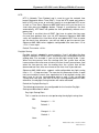
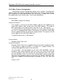
3-4-6. Spanning Tree Configuration
The Spanning Tree Protocol (STP) is a standardized method (IEEE 802.1D)
for avoiding loops in switched networks. When STP is enabled, ensure that only
one path is active between any two nodes on the network at a time. User can
enable Spanning Tree Protocol on converter’s web management and then set up
other advanced items. We recommend that you enable STP on all converters to
ensure a single active path on the network.
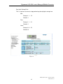
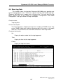
3-4-6-1. STP Status
Function name:
STP Status
Function description:
In the Spanning Tree Status, user can read 12 parameters to know STP
current status. The 12 parameters’ description is listed in the following table.
Parameter description:
STP Status:
Show the current STP Enabled / Disabled status. Default is “Disabled”.
Bridge ID:
Show converter’s bridge ID, which stands for the MAC address of this
converter.
Bridge Priority:
Show this converter’s current bridge priority setting. Default is 32768.
Designated Root:
Show root bridge ID of this network segment. If this converter is a root
bridge, the “Designated Root” will show this converter’s bridge ID.
Designated Priority:
Show the current root bridge priority.
Root Port:
Show port number connected to root bridge with the lowest path cost.
Root Path Cost:
Show the path cost between the root port and the designated port of the
root bridge.
Current Max. Age:
Show the current root bridge maximum age time. Maximum age time is
used to monitor if STP topology needs to change. When a bridge does
not receive a hello message from root bridge until the maximum age time
is counted down to 0, the bridge will treat the root bridge malfunctioned
and issue a Topology Change Notification (TCN) BPDU to all other
bridges.
Publication date: October, 2005
Revision 1.0
57
Signamax 065-1600 series managed media converter
All bridges in the LAN will re-learn and determine which the root bridge is.
Maximum Age time is assigned by root bridge in unit of seconds. Default
is 20 seconds.
Current Forward Delay:
Show the current root bridge forward delay time. The value of Forward
Delay time is set by root. The Forward Delay time is defined as the time
spent from Listening state moved to Learning state or from Learning
state moved to Forwarding state of a port in bridge.
Hello Time:
Show the current hello time of the root bridge. Hello time is a time
interval specified by root bridge, used to request all other bridges
periodically sending hello message every “hello time” seconds to the
bridge attached to its designated port.
Topology Change Count:
STP Topology Change Count expresses the time spent in unit of seconds
since the beginning of the Spanning Tree Topology Change to the end of
the STP convergence. Once the STP change is converged, the Topology
Change count will be reset to 0. The figures showing in the screen may
not be the exact time it spent but very close to, because the time is
eclipsing.
Time Since Last Topology Change:
Time Since Last Topology Change is the accumulated time in unit of
seconds the STP has been since the last STP Topology Change was
made. When Topology Change is initiated again, this counter will be
reset to 0. And it will also count again once STP topology Change is
completed.
Fig. 3-16
Publication date: October, 2005
Revision 1.0
58
Signamax 065-1600 series Managed Media Converter
3-4-6-2. STP Configuration
The STP, Spanning Tree Protocol, actually includes RSTP. In the Spanning
Tree Configuration, there are six parameters open for the user to configure as the
user desires. Each parameter description is listed below.
Function name:
STP State Setting
Function description:
User can set the following Spanning Tree parameters to control STP function
enable/disable, select mode RSTP/STP and affect STP state machine
behavior to send BPDU in this converter. The default setting of Spanning Tree
Protocol is “Disable”.
Parameter description:
Spanning Tree Protocol:
Set 802.1W Rapid STP function Enable / Disable. Default is “Disable”
Bridge Priority:
The lower the bridge priority is, the higher priority it has. Usually, the
bridge with the highest bridge priority is the root. If you want to have the
Signamax 065-1600 series as the root bridge, you can set this value
lower than that of the bridge in the LAN. The valid value is 0 ~ 61440.
The default is 32768.
Hello Time:
Hello Time is used to determine the periodic time to send normal BPDU
from designated ports among bridges. It decides how long a bridge
should send this message to other bridge to tell I am alive. When
Signamax 065-1600 series is the root bridge of the LAN, for example, all
other bridges will use the hello time assigned by Signamax 065-1600
series to communicate with each other. The valid value is 1 ~ 10 in unit
of second.
Default is 2 seconds.
Max. Age:
When Signamax 065-1600 series is the root bridge, the whole LAN will
apply this figure set by Signamax 065-1600 series as their maximum age
time. When a bridge received a BPDU originated from the root bridge
and if the message age conveyed in the BPDU exceeds the Max. Age of
the root bridge, the bridge will treat the root bridge malfunctioned and
issue a Topology Change Notification (TCN) BPDU to all other bridges.
All bridges in the LAN will re-calculate and determine who the root bridge
is. The valid value of Max. Age is 6 ~ 40 seconds. Default is 20 seconds.
Publication date: October, 2005
Revision 1.0
59
Signamax 065-1600 series managed media converter
Forward Delay:
You can set the root bridge forward delay time. This figure is set only by
the root bridge. The forward delay time is defined as the time spent from
Listening state moved to Learning state and also from Learning state
moved to Forwarding state of a port in bridge. The forward delay time
contains two states, Listening state to Learning state and Learning state
to Forwarding state. It assumes that if the forward delay time is 15
seconds, then the total forward delay time will be 30 seconds. This has
much to do with the STP convergent time which will be more than 30
seconds because some other factors.
The valid value is 4 ~ 30 seconds, default is 15 seconds.
Force Version:
Two options are offered for the user’s choosing STP algorithm. One is
RSTP and the other is STP. If STP is chosen, RSTP will run as a legacy
STP. Signamax 065-1600 series supports RSTP (802.1w) which is
backward compatible with STP (802.1d).
Fig. 3-17
Publication date: October, 2005
Revision 1.0
60
Signamax 065-1600 series Managed Media Converter
Function name:
Port Setting
Function description:
In the STP Port Setting, one item selection and five parameters settings are
offered for user’s setup. User can disable and enable each port by selecting
each Port Status item. User also can set “Path Cost” and “Priority” of each port
by filling in the desired value and set “Admin Edge Port” and “Admin Point To
Point” by selecting the desired item.
Parameter description:
Port Status:
It displays the current state of a port. We cannot manually set it because
it displays the status only. There are three possible states (according to
the 802.1w specification):
DISCARDING state indicates that this port can neither forward packets
nor contribute learning knowledge.
Notice: Three other states (Disable state, BLOCKING state and LISTENING
state) defined in the 802.1d specification are now all represented as
DISCARDING state.
LEARNING state indicates this port can now contribute its learning
knowledge but cannot forward packets still.
FORWARDING state indicates this port can both contribute its learning
knowledge and forward packets normally.
Path Costs:
The contribution value of the path through this port to the Root Bridge.
STP algorithm determines a best path to Root Bridge by calculating the
sum of path cost contributed by all ports on this path. A port with a
smaller path cost value would become the Root Port more possibly. The
range is 0 – 200,000,000. In the Signamax 065-1600 series, a path cost
with a 0 value means "automatic", this will automatically assign the path
cost value defined by IEEE 802.1w. Default: 0
802.1w RSTP recommended value: (Valid range: 1 – 200,000,000)
10 Mbps
: 2,000,000
100 Mbps
: 200,000
1 Gbps
: 20,000
Priority:
Priority here means Port Priority. Port Priority and Port Number are
mixed to form the Port ID. Port IDs are often compared in order to
determine which port of a bridge would become the Root Port. The range
Publication date: October, 2005
Revision 1.0
61
Signamax 065-1600 series managed media converter
is 0 – 240. Default is 128.
Publication date: October, 2005
Revision 1.0
62
Signamax 065-1600 series Managed Media Converter
Admin Edge Port:
If user selects “Yes”, this port will be an edge port. An Edge Port is a port
connected to a device that knows nothing about STP or RSTP. Usually,
the connected device is an end station. Edge Ports will immediately
transit to forwarding state. User can select “Yes” or “No”. Default: No
Admin Point To Point:
We say a port is on a point-to-point link if the port is in full-duplex mode.
RSTP fast convergence can only happen on a point-to-point link. To
determine if this port is on a point-to-point link is by auto-detecting the
port’s duplex mode if the parameter is set to “Auto”. If the parameter is
set “True”, the port is unconditionally considered to be on a point-to-point
link. If the parameter is set to “False”, fast transition to Forwarding state
will not happen on this port. User can select “Auto”, “True” or “False”.
Default: Auto
M Check:
Migration Check. It forces the port sending out an RSTP BPDU instead
of a legacy STP BPDU at the next transmission. The only benefit of this
operation is to make the port quickly get back to act as an RSTP port.
Click <M Check> button to send a RSTP BPDU from the port you
specified.
Fig. 3-18
Publication date: October, 2005
Revision 1.0
63
Signamax 065-1600 series managed media converter
3-4-7. Filtering Configuration
The filtering function in Signamax 065-1600 series is used to filter unwanted
MAC address from accessing the converter based on some simple rules. Signamax
065-1600 series provides three types of filtering function for security configuration.
They are Allowed Forwarding MAC Address, Port Security Setting and Denied
Forwarding MAC Address. You can configure it for different purposes of application.
Here we list two examples for your reference.
Example 1:
Assumes administrator wishes a specified station can only access
the converter from a specified port and the traffic from all other stations is
rejected by that specified port. How should we configure Signamax 0651600 series for the case?
Solution:
First, enter the function “Allowed Forwarding MAC Address” to add
an entry with the MAC address of the specified station on the Allowed
Forwarding table of the specified port. The Security Port of the specified
port should be then enabled in the “Port Security Setting” function. Finishing
this process, the specified port will not allow any other station to access the
converter except the specified station. And if this specified station is moved
to other port, it cannot access the converter, either.
Example 2:
Assumes an administrator wishes to deny a specified station from
accessing the converter, which is to isolate the specified station from the
converter. How should we configure Signamax 065-1600 series for the case?
Solution:
For denying a specified station, it is easy. You just have to use the
function “Denied Forwarding MAC Address” to configure it. Enter this
function and press the <Add> button to add the MAC address of the
specified station, which is rejected to access the converter. The Deny
Forwarding function is global. It is applied to the whole converter.
Publication date: October, 2005
Revision 1.0
64
Signamax 065-1600 series Managed Media Converter
Function name:
Allowed Forwarding MAC Address
Function description:
Allowed Forwarding MAC Address is a function to allow the user in the
Allowed Forwarding table to access a specified port of the converter. Allowed
Forwarding table associated with a specified port of a converter is setup by
manually inputting MAC address and its alias name. The data in the table is
kept until Signamax 065-1600 series is powered off. The traffic with the source
MAC address listed in the Allowed Forwarding Table can only access the
converter from the port associated. The MAC address associated with the
specified port cannot access any other port of the converter. All of the above
settings will take effect only when “Port Security Setting” function of the
associated port is enabled.
For adding a MAC address entry in the allowed table, you just need to fill in
three parameters: MAC address, associated port, and priority. Just select the
MAC address entry you want and click <Delete> button, you also can remove
it.
Parameter description:
Allowed Forwarding Table:
A table stored MAC address entry with associated port and priority, is
used to provide the function to allow the users listed in this table to
access the associated port of the converter.
MAC Address:
It is a six-byte long Ethernet hardware address and usually expressed by
hex and separated by hyphens. For example,
00 – 40 - C7 - D6 – 00 - 01
Port:
Ports of the Signamax 065-1600 series.
Priority:
This is for traffic priority. User can configure a MAC address high priority
or low priority. If MAC address is configured high priority, the packet with
that DA or SA will be put into the high priority queue and be transmitted
with high priority. If MAC address is configured low priority, the packet
with that MAC address will be transmitted with low priority.
Publication date: October, 2005
Revision 1.0
65
Signamax 065-1600 series managed media converter
Fig. 3-19
Function name:
Port Security Setting
Function description:
The usage of Port Security has to combine with Allowed Forwarding MAC
Address function as mentioned above. In this function, you can enable it if you
select the port. If the user ticks each port, then, the ticked port will stop
learning MAC Address and block any incoming packet except that the packet
with the MAC Address is listed in the Forwarding MAC Address table
associated with that port. The <Apply> button is for user to click to let the
system take effect immediately.
Publication date: October, 2005
Revision 1.0
66
Signamax 065-1600 series Managed Media Converter
Fig. 3-20
Publication date: October, 2005
Revision 1.0
67
Signamax 065-1600 series managed media converter
Function name:
Denied Forwarding MAC Address
Function description:
Denied Forwarding MAC Address is a function that denies the packet
forwarding if the packet’s MAC Address is listed in the filtering MAC Address
table. User can very easily maintain the table by filling in MAC Address field
individually. User also can insert or delete each entry by clicking <Add> or
<Delete> button.
Parameter description:
Denied Forwarding Table:
A table stored MAC address entry is used to provide the function to reject
the users listed in this table to access the converter.
MAC Address:
It is a six-byte long Ethernet hardware address and usually expressed by
hex and separated by hyphens. For example,
00 – 40 - C7 - D6 – 00 - 01
Fig. 3-21
Publication date: October, 2005
Revision 1.0
68
Signamax 065-1600 series Managed Media Converter
3-4-8. VLAN Configuration
VLAN configuration is used to partition your LAN into small ones as your
demand. Properly configuring it, you can gain not only improving security and
increasing performance but greatly reducing VLAN management.
Signamax 065-1600 series supports Tag-based VLAN (802.1q) as well as
protocol VLAN (802.1v). Tag-based VLAN (802.1q) also associates with GVRP for
the management of dynamic tag-based VLAN. You can make VLAN configurations
via the function VLAN Enable/Disable (VLAN State Setting) and VLAN Port VID
Setting to configure VLAN parameters in the web user interface.
Function name:
VLAN Enable/Disable (VLAN State Setting)
Function description:
The VLAN State Setting function includes two modes: Disable and Enable, you
can choose one of them by pulling down the list and pressing the
<Downward> arrow key. Then, click <Apply> button, the settings will take
affect immediately.
Parameter description:
VLAN Mode:
Disable:
Stop VLAN function on Signamax 065-1600 series. In this mode, no
VLAN is applied to Signamax 065-1600 series. This is the default
setting.
Enable:
Effect VLAN function on Signamax 065-1600 series. In this mode,
VLAN is applied to Signamax 065-1600 series.
Fig. 3-22 VLAN State Setting
Publication date: October, 2005
Revision 1.0
69
Signamax 065-1600 series managed media converter
Function name:
VLAN Port VID Setting (for Tag Only)
Function description:
This design is concerning the CPE site customer, there are not VLAN aware
network device for tagged based VLAN application. The Signamax 065-1600
series plays the role of the edge of VLAN aware network with tagged packets
for upstream and untagged for downstream.
Parameter description:
Port:
Port of the Signamax 065-1600 series.
PVID:
In VLAN Port VID Setting, user can input VID number to each port. The
range of VID is from 1 to 4094.
Default: 1
Tag:
The egress rule configuration is to make decision for packets tagging out
or packets un-tagging out from the configured port.
Default: Untag
Fig. 3-23 VLAN Port VID Setting
Publication date: October, 2005
Revision 1.0
70
Signamax 065-1600 series Managed Media Converter
3-4-9. Trap/Alarm Configuration
Function name:
Trap Events Configuration
Function description:
The Trap Events Configuration function is used to enable the Managed Media
Converter to send out the trap information while pre-defined trap events
occurred. Signamax 065-1600 series offers 16 different trap events to users
for converter management. The trap information can be sent out in three ways,
including e-mail, mobile phone SMS (short message system) and Trap. The
message will be sent while users tick () the trap event individually on the
web page shown as below.
Fig. 3-24
Parameter description:
STP Topology Changed: E-mail, SMS and Trap
E-mail
: Send “STP Topology Changed” alarm message by E-mail
when the STP topology changed event happened.
Default: Unchecked ()
SMS
: Send “STP Topology Changed” alarm message by Short
Message System when the STP topology changed event
happened. Default: Unchecked ()
Trap
: Send Trap message to SNMP Trap Receiver when the STP
topology changed event happened.
Default: Checked ()
Publication date: October, 2005
Revision 1.0
71
Signamax 065-1600 series managed media converter
STP Disabled: E-mail, SMS and Trap
E-mail
: Send “STP Disabled” alarm message by E-mail when the
STP function was disabled.
Default: Unchecked ()
SMS
: Send “STP Disabled” alarm message by Short Message
System when the STP function was disabled.
Default: Unchecked ()
Trap
: Send Trap message to SNMP Trap Receiver when the STP
function was disabled.
Default: Unchecked ()
STP Enabled: E-mail, SMS and Trap
E-mail
: Send “STP Enabled” alarm message by E-mail when the
STP function was enabled.
Default: Unchecked ()
SMS
: Send “STP Enabled” alarm message by Short Message
System when the STP function was enabled.
Default: Unchecked ()
Trap
: Send Trap message to SNMP Trap Receiver when the STP
function was enabled.
Default: Unchecked ()
Temperature Abnormal: E-mail, SMS and Trap
Issue alarm message via E-mail and SMS when the Signamax 065-1600
o
o
series’ case inside temperature was over 50 C or under 4 C. The default
setting is shown as below:
E-mail
: Send “Temperature Abnormal” alarm message by E-mail
o
when the case inside temperature was over 52 C or under
o
4 C. Default: Unchecked ()
SMS
: Send “Temperature Abnormal” alarm message by Short
Message System when the case inside temperature was
o
o
over 52 C or under 4 C. Default: Unchecked ()
Trap
: Send Trap message to SNMP Trap Receiver when the
o
o
case inside temperature was over 52 C or under 4 C.
Default: Checked ()
Publication date: October, 2005
Revision 1.0
72
Signamax 065-1600 series Managed Media Converter
Temperature Normal: E-mail, SMS and Trap
Issue alarm message via E-mail and SMS when the Signamax 065-1600
o
o
series’ case inside temperature recovered from (over 52 C or under 4 C)
o
o
to under (48 C and over 4 C). The default setting is shown as below:
E-mail
: Send “Temperature Normal” alarm message by E-mail
when the case inside temperature recovered to normal
status. Default: Unchecked ()
SMS
: Send “Temperature Normal” alarm message by Short
Message System when the case inside temperature
recovered to normal status. Default: Unchecked ()
Trap
: Send Trap message to SNMP Trap Receiver when the
case inside temperature recovered to normal status.
Default: Checked ()
Case Opened: E-mail, SMS and Trap
Issue alarm message via E-mail and SMS when the Signamax 065-1600
series’ case was opened. The default setting is shown as below:
E-mail
: Send “Case Opened” alarm message by E-mail when
case is opened. Default: Unchecked ()
SMS
: Send “Case Opened” alarm message by Short Message
System when case is opened. Default: Unchecked ()
Trap
: Send Trap message to SNMP Trap Receiver when case
is opened. Default: Checked ()
Case Closed: E-mail, SMS and Trap
Issue alarm message via E-mail and SMS when the Signamax 065-1600
series’ case was closed. The default setting is shown as below:
E-mail
: Do not send “Case Closed” alarm message by E-mail
when case is closed. Default: Unchecked ()
SMS
: Do not send “Case Closed” alarm message by Short
Message System when case is closed.
Default: Unchecked ()
Trap
: Send Trap message to SNMP Trap Receiver when case
is closed. Default: Checked ()
Publication date: October, 2005
Revision 1.0
73
Signamax 065-1600 series managed media converter
Flash Write Fail: E-mail, SMS and Trap
Default setting is as below:
E-mail
: Do not send alarm message by E-mail when the device
happened “Flash Write Fail” event.
Default: Unchecked ()
SMS
: Do not send short message to mobile phone when the
device happened “Flash Write Fail” event.
Default: Unchecked ()
Trap
: Send Trap message to SNMP Trap Receiver when the
device happened “Flash Write Fail” event.
Default: Checked ()
FAN Abnormal: E-mail, SMS and Trap
E-mail
: Send “FAN Abnormal” alarm message by E-mail when the
FAN was abnormal. Default: Unchecked ()
SMS
: Send “FAN Abnormal” alarm message by Short Message
System when the FAN was abnormal.
Default: Unchecked ()
: Send Trap message to SNMP Trap Receiver when the FAN
was abnormal. Default: Checked ()
Trap
FAN Normal: E-mail, SMS and Trap
E-mail
: Send “FAN Normal” alarm message by E-mail when the FAN
was normal. Default: Unchecked ()
SMS
: Send “FAN Normal” alarm message by Short Message
System when the FAN was normal. Default: Unchecked ()
Trap
: Send Trap message to SNMP Trap Receiver when the FAN
was normal. Default: Checked ()
FAN/Temperature Fail: E-mail, SMS and Trap
E-mail
: Send “FAN/Temperature Fail” alarm message by E-mail
when the FAN was abnormal and Temperature was over
o
60 C at the same time. Default: Unchecked ()
SMS
: Send “FAN/Temperature Fail” alarm message by Short
Message System when the FAN was abnormal and
Temperature was over 60oC at the same time.
Default: Unchecked ()
Trap
: Send Trap message to SNMP Trap Receiver when the FAN
was abnormal and Temperature was over 60oC at the same
time. Default: Checked ()
Publication date: October, 2005
Revision 1.0
74
Signamax 065-1600 series Managed Media Converter
Cold Start: E-mail, SMS and Trap
Default setting is as below:
E-mail
: Do not send alarm message by E-mail when the device
happened restart event by cold booting method.
Default: Unchecked ()
SMS
: Do not send short message to mobile phone when the
device happened restart event by cold booting method.
Default: Unchecked ()
Trap
: Send Trap message to SNMP Trap Receiver when the
device happen restarted event by cold booting method.
Default: Checked ()
Warm Start: E-mail, SMS and Trap
Default setting is as below:
E-mail
: Do not send alarm message by E-mail when the device
happened restart event by warm booting method.
Default: Unchecked ()
SMS
: Do not send short message to mobile phone when he
device happened restart event by warm booting method.
Default: Unchecked ()
Trap
: Send Trap message to SNMP Trap Receiver when he
device happened restart event by warm booting method.
Default: Checked ()
Link Down: E-mail, SMS and Trap
Default setting is as below:
E-mail
: Send alarm message by E-mail when the device
Ethernet port happened link down event.
Default: Unchecked ()
SMS
: Send short message to mobile phone when the device
Ethernet port happened link down event.
Default: Unchecked ()
Trap
: Send Trap message to SNMP Trap Receiver when the
device Ethernet port happened link down event.
Default: Checked ()
Publication date: October, 2005
Revision 1.0
75
Signamax 065-1600 series managed media converter
Link Up: E-mail, SMS and Trap
Default setting is as below:
E-mail
: Do not send alarm message by E-mail when the device
Ethernet port happened link up event.
Default: Unchecked ()
SMS
: Do not send short message to mobile phone when the
device Ethernet port happened link up event.
Default: Unchecked ()
Trap
: Send Trap message to SNMP Trap Receiver when the
device Ethernet port happened link up event.
Default: Checked ()
Authentication Failure: E-mail, SMS and Trap
Default setting is as below:
E-mail
: Do not send alarm message by E-mail when the device
received a SNMP get or set request with a wrong
community name. Default: Unchecked ()
SMS
: Do not send short message to mobile phone when the
device received a SNMP get or set request with a wrong
community name. Default: Unchecked ()
Trap
: Send Trap message to SNMP Trap Receiver when the
device received a SNMP get or set request with a wrong
community name. Default: Checked ()
Publication date: October, 2005
Revision 1.0
76
Signamax 065-1600 series Managed Media Converter
Function name:
Alarm Configuration
Function description:
Alarm configuration is used to configure the persons who should receive the
alarm message via either email or SMS, or both. It depends on your settings.
An email address or a mobile phone number has to be set in the web page of
alarm configuration (See Fig.3-25). Then, user can read the trap information
from the email or the mobile phone. This function provides 6 email addresses
and 6 mobile phone numbers at most. The 16 different trap events will be sent
out to SNMP Manager when trap event occurs. After ticking trap events, you
can fill in your desired email addresses and mobile phone numbers. Then,
please click <Apply> button to complete the alarm configuration. It will take
effect in a few seconds.
Note: SMS may not work in your mobile phone system. It is customized for different
systems.
Fig. 3-25
Parameter description:
Email:
Mail Server: the IP address of the server transferring your email.
Username: your username on the mail server.
Password: your password on the mail server.
Email Address 1 – 6: email address that would like to receive the
alarm message.
Publication date: October, 2005
Revision 1.0
77
Signamax 065-1600 series managed media converter
SMS:
SMS Server: the IP address of the server transferring your SMS.
Default: 203.66.172.131
Username: your username in ISP.
Password: your username in ISP.
Mobile Phone 1-6: the mobile phone number that would like to
receive the alarm message.
Publication date: October, 2005
Revision 1.0
78
Signamax 065-1600 series Managed Media Converter
3-4-10. Save Configuration
Signamax 065-1600 series supports three copies of configuration, including
default configuration, working configuration and user configuration for your
configuration management. All of them are listed and described below respectively.
Default Configuration:
This is the ex-factory setting and cannot be altered.
Working Configuration:
It is the configuration you are using currently and can be changed any time.
The configurations you are using are saved into this configuration file. This is
updated each time as you press <Apply> button.
User Configuration:
It is the configuration file for the specified or backup purposes and can be
updated while having confirmed the configuration. You can retrieve it by performing
Restore User Configuration.
Function name:
Save As User Configuration
Function description:
Save As User Configuration function can save the current configuration as a
user configuration file in flash memory.
Fig. 3-26
Publication date: October, 2005
Revision 1.0
79
Signamax 065-1600 series managed media converter
Function name:
Restore Default Configuration
Function description:
Restore Default Configuration function can retrieve the ex-factory setting to
replace the working configuration.
Fig. 3-27
Function name:
Restore User Configuration
Function description:
Restore User Configuration function can retrieve the previous confirmed
working configuration stored in the flash memory to update user’s current
working configuration. When completing to restore the configuration, the
system’s working configuration is updated and will be changed its working
mode by the new configuration immediately.
Publication date: October, 2005
Revision 1.0
80
Signamax 065-1600 series Managed Media Converter
Fig. 3-28
Publication date: October, 2005
Revision 1.0
81
Signamax 065-1600 series managed media converter
3-5. Diagnostics
Function name:
Diagnostics
Function description:
Diagnostics function provides a set of basic system diagnosis. It let users
know that whether the system is health or needs to be fixed. The basic system
check includes UART test, DRAM test, Flash test, Temperature detection,
Case detection and Fan RPM detection.
Fig. 3-29
Function name:
Loopback Test
Function description:
In the Loopback Test function, there are two different loopback tests. One is
Internal Loopback Test and the other is External Loopback Test. The former
test function will not send the test signal outside the Signamax 065-1600
series converter box. The test signal only wraps around in the Signamax 0651600 series converter box. As to the latter test function, it will send the test
signal to its link partner. If you do not have them connected to active network
devices, i.e. the ports are link down, Signamax 065-1600 series will report the
port numbers failed. If they all are ok, it just shows OK.
Note: Whatever you choose Internal Loopback Test or External Loopback Test,
these two functions will interfere with the normal system working, and all
packets in sending and receiving also will stop temporarily.
Publication date: October, 2005
Revision 1.0
82
Signamax 065-1600 series Managed Media Converter
Fig. 3-30
Function name: Ping Test
Function description:
Ping Test function is a tool for detecting if the target device is alive or not
through ICMP protocol which abounds with report messages. Signamax
065-1600 series provides Ping Test function to let you know that if the target
device is available or not. You can simply fill in a known IP address and
then click <Ping Now> button. After a few seconds, the Signamax 0651600 series converter will report to you whether the pinged device is alive
or dead.
Parameter description:
IP Address: an IP address with the version of v4, e.g. 192.168.1.1.
Default Gateway: IP address of the default gateway.
For more details, please see the section of IP address in Chapter 2.
Publication date: October, 2005
Revision 1.0
83
Signamax 065-1600 series managed media converter
Fig. 3-31
Publication date: October, 2005
Revision 1.0
84
Signamax 065-1600 series Managed Media Converter
Function name:
Auto Ping Configuration
Function description:
Auto Ping Configuration is used to test one or two target devices periodically
with a period of time, which is programmable. This can detect that if the target
device or the device itself is dead, and it helps you debug the network
problems. Signamax 065-1600 series can auto-ping two network devices at
the same time.
Parameter description:
Ping Interval:
This parameter is used to instruct Signamax 065-1600 series to
periodically ping the target device using the time interval you assigned.
Programmable time range: 1 – 60 minutes. Default: 10 minutes.
Host IP Address 1/2 and Current Default Gateway:
These are IP addresses with the format of version 4. For more
information, please see the section of IP address in Chapter 2.
Fig. 3-32
Publication date: October, 2005
Revision 1.0
85
Signamax 065-1600 series managed media converter
3-6. Show Log Data
This function shows the log data. Signamax 065-1600 series provides one
type of trap log data for users. There are 11 private trap logs and 5 public trap logs.
Signamax 065-1600 series supports total 120 log entries. For more details on log
items, please refer to the section of Trap/Alarm Configuration and SNMP
Configuration. User logs include user login and logout.
Function name:
Trap Log Data
Function description:
The Trap Log Data is displaying the log items including all SNMP Private Trap
events, SNMP Public traps and user logs occurred in the system. In the report
table, No, Time and Events are three fields contained in each trap record.
Parameter description:
No:
Display the order number that the trap happened.
Time:
Display the time that the trap happened.
Events:
Display the trap event name.
Fig. 3-33
Publication date: October, 2005
Revision 1.0
86
Signamax 065-1600 series Managed Media Converter
Function name:
Illegal Access Report Status
Function description:
User can select “Enable” or Disable” the illegal access report function. If select
disabled illegal access report, the illegal access report will not log any illegal
access events. If select enabled illegal access report, the illegal access events
will be logged.
Parameter description:
Illegal Access Report Status:
You can enable/disable the mode of illegal access report.
Default: Enable.
Fig. 3-34
Publication date: October, 2005
Revision 1.0
87
Signamax 065-1600 series managed media converter
Function name:
Illegal Access Report
Function description:
The Illegal Access Report function is to display the unauthorized users
accessing Signamax 065-1600 series. If Allowed forwarding or Denied
forwarding was configured, Illegal Access Report starts recording which illegal
user(s) try to access. At this moment, illegal users will be rejected to serve in
Signamax 065-1600 series. This can highly improve network security and
traffic management.
In this table, Signamax 065-1600 series records those users who violate
Allowed Forwarding rule and Denied Forwarding rule. Besides, illegal access
report can also show the alias name of users, instead of MAC address only, if
you configured MAC alias name in advance.
Each entry in illegal access report comprises six fields, including record order
number, Source Address, Destination Address, port, time and type. Signamax
065-1600 series supports 32 record entries for illegal access report by
applying ring structure. That means if there is no room for the new record, it
will overwrite the oldest record in the ring.
Parameter description:
No.: Display the order number that the trap happened.
Source Address: MAC Source Address.
Dest. Address: MAC Destination Address.
Port: Display the port that the illegal access happened.
Time: Current System Time.
Type: Violating Allowed Table or Violating Denied Table.
Publication date: October, 2005
Revision 1.0
88
Signamax 065-1600 series Managed Media Converter
Fig. 3-35 Illegal Access Report
Publication date: October, 2005
Revision 1.0
89
Signamax 065-1600 series managed media converter
Function name:
MAC Alias
Function description:
MAC Alias function is used to let you assign MAC address a plain English
name, which will help you tell which MAC address belongs to which user in the
illegal access report. At the initial time, it shows all pairs of the existed alias
name and MAC address.
There are three MAC alias functions in this function folder, including MAC Alias
Add, MAC Alias Edit and MAC Alias Delete. You can click <Create> button to
add a new alias name for a specified MAC address, or mark an existed entry
to edit/delete it. Alias name must be composed of A-Z, a-z and 0-9 only and
has a Maximum length of 17 characters.
Fig. 3-36 MAC Alias
Publication date: October, 2005
Revision 1.0
90
Signamax 065-1600 series Managed Media Converter
Function name:
MAC Alias Add
Function description:
In the MAC Alias function, it is used to let you add an association between
MAC address and a plain English name. User can click <Create> button to
add a new record with name.
Parameter description:
MAC Address:
New Entry:
If you want to apply a name to a MAC address which does not exist
in the MAC address table, you must choose New Entry to fill in the
MAC address by yourself or select a MAC address in the pull-down
menu by pressing the <Downward> arrow key. You can also select
one of the MAC addresses in the list, and then assign it an alias
name for mnemonic name.
MAC Alias:
MAC alias name you assign.
Note: If there are too many MAC addresses learned in the table, we recommend
you inputting the MAC address and alias name directly.
Fig. 3-37 Add MAC Alias
Publication date: October, 2005
Revision 1.0
91
Signamax 065-1600 series managed media converter
Function name:
MAC Alias Edit/Delete
Function description:
MAC Alias Edit/Delete function is used to let you modify/remove an alias name
to a MAC address. You can select an existed MAC address or alias name to
modify/remove.
Parameter description:
MAC Address:
The Ethernet MAC address of the end station.
MAC Alias:
A mnemonic name for the end station.
Fig. 3-38 Delete MAC Alias
Publication date: October, 2005
Revision 1.0
92
Signamax 065-1600 series Managed Media Converter
3-7. Software Upgrade
Software upgrade tool is used to help upgrade the software function in order
to fix or improve the function. Signamax 065-1600 series provides a TFTP client for
software upgrade. This can be done through Ethernet. For more details about
upgrade procedures, please refer to Appendix D.
Function name:
Software Upgrade
Function description:
Signamax 065-1600 series supports TFTP upgrade tool for upgrading software.
If you assure to upgrade software to a newer version one, you must follow two
procedures:
1.) Specifying the IP address where TFTP server locates. In this field, the IP
address of your TFTP server should be filled in.
2.) Specifying what the filename and where the file is. You must specify full path
and filename.
Once you press <Apply> button, Signamax 065-1600 series will prompt the
screen for you to reconfirm. Then, Signamax 065-1600 series starts downloading
software from TFTP server if you choose <OK> button. It will be just back to
“Software Upgrade” if you choose <Cancel> button. If your download is not
successful, Signamax 065-1600 series will also be back to “Software Upgrade”, and
it will not upgrade the software as well.
When download is completed, Signamax 065-1600 series starts upgrading
software. A reboot message will be prompted after completing upgrading software.
At this time, you must reboot Signamax 065-1600 series to have new software
worked.
Note: Software upgrade is hazardous if power is off. You must do it carefully.
Parameter description:
TFTP Server: A TFTP server stored the image file you want to upgrade.
Path and Filename: File path and filename stored the image file you want to
upgrade.
Publication date: October, 2005
Revision 1.0
93
Signamax 065-1600 series managed media converter
Fig. 3-39
Publication date: October, 2005
Revision 1.0
94
Signamax 065-1600 series Managed Media Converter
3-8. Reboot
We offer you many ways to reboot Signamax 065-1600 series, including
power up, hardware reset and software reset. You can press the RESET button in
the front panel to reset Signamax 065-1600 series. After upgrading software,
changing IP configuration or changing VLAN mode configuration, then you must
reboot to have the new configuration taken effect. Here we are discussing is
software reset for the “reboot” in the main menu.
Function name:
Reboot
Function description:
Reboot Signamax 065-1600 series. Reboot takes the same effect as the
RESET button on the front panel of Signamax 065-1600 series converter. It
will take around thirty (30) seconds to complete the system boot.
Fig. 3-40
Publication date: October, 2005
Revision 1.0
95
Signamax 065-1600 series managed media converter
3-9. Logout
You can manually logout by performing Logout function. In Signamax 0651600 series, it provides another way to logout. You can configure it to logout
automatically.
Function name:
Logout
Function description:
Signamax 065-1600 series allows you to logout the system to prevent other
users from the system without the permission. If you do not logout and exit the
browser,
Signamax 065-1600 series will automatically have you logout.
Besides this manually logout and implicit logout, you can click <Auto Logout>
radian at the right-top corner to explicitly ON/OFF this logout function.
Parameter description:
Auto Logout:
Select On/OFF. Default is ON. If it is “ON”, and no action and no key is
stroke as well in any function screen more than 3 minutes, Signamax
065-1600 series will have you logout automatically.
Fig. 3-41
Publication date: October, 2005
Revision 1.0
96
Signamax 065-1600 series Managed Media Converter
4. Operation of
Menu-driven Console
1. The Managed Media Converter Signamax 065-1600 series also provides a textbased menu-driven console accessible by an RS-232 terminal or the Ethernet
Port (telnet) to manage and monitor the port activity. Usually, in order to have
the device connected to the management station, the console is used to change
the settings such as the IP address for the first time. For detailed connection
steps, please refer to Section 2-2-3 in Chapter 2.
Now, you can use the console to modify the IP setting through the telnet
program.
The default values of Signamax 065-1600 series converter are as follows:
IP Address
:192.168.1.1
Subnet Mask
:255.255.255.0
Default Gateway
:192.168.1.254
Username
:admin
Password
:admin
2. For instance, you can run telnet 192.168.1.1 in Windows 95/98/2000/XP…, and
so on, then, enter the username and password as above. The screen is shown
as follows:
Fig. 4-1
Publication date: October, 2005
Revision 1.0
97
Signamax 065-1600 series managed media converter
4-1. Text-based Menu-driven Management Overview
The text-based main menu will be shown up after you fill in “admin” to serve
as username as well as password and press the <Enter> key. On the menu, user
can use arrow keys to move cursor to each item and press the <Enter> key to
select the item you would like. The <Esc> key is used to escape to the upper menu
page layer.
The main functions will be listed in the middle of console. The main functions
contain “Port Status and Counter”, “System Information”, “Configuration”,
“Diagnostics”, “Show Log Data”, “Software Upgrade”, “Reboot” and “Logout”. The
details of the main functions will be introduced in the following sections.
Fig. 4-2
Publication date: October, 2005
Revision 1.0
98
Signamax 065-1600 series Managed Media Converter
Function name:
System Information
Function description:
Show the basic system information.
Fig. 4-3
Parameter description:
Model Name:
The model name of this product.
System Description:
Managed Media Converter
Location:
The physical location of this converter. User-defined.
Contact:
The contact person or organization in charge of the maintenance of this
converter. User-defined.
System Up Time:
The time accumulated since this converter is powered up. Its format is
day, hour, minute, second.
Current Time:
Shows the system time of the Signamax 065-1600 series converter. Its
format: day of week, month, day, hours : minutes : seconds, year. For
instance, Wed, Apr. 06, 12:10:10, 2004.
Publication date: October, 2005
Revision 1.0
99
Signamax 065-1600 series managed media converter
MAC Address:
It is the MAC address of the management agent in this converter.
BIOS Version:
The version of the BIOS in this converter.
Firmware Version:
The firmware version in this converter.
Hardware-Mechanical:
The Hardware and Mechanical version of this converter. The figure
before the hyphen is the version of electronic hardware; the one after the
hyphen is the mechanical version.
RAM Size:
The size of the DRAM in this converter.
Flash Size:
The size of the flash memory in this converter.
Series Number:
The serial number is assigned by manufacturer.
Device Port:
Show all types and numbers of the port. In Signamax 065-1600 series,
there are one serial port, one TP port and one FX port.
Temperature:
The air temperature inside of this converter.
IP Address:
The IP address that indicates where Signamax 065-1600 series is
located (e.g. default IP address of Signamax 065-1600 series is
192.168.1.1).
Case Detection:
Show the status of the upper case of this converter. When the case is lid
off, it shows “Open”; otherwise, it shows “Close”.
Fiber Port:
Show the connector type (e.g. SC/LC), fiber mode (e.g. Single/Multi
mode) status and number of fiber port.
Publication date: October, 2005
Revision 1.0
100
Signamax 065-1600 series Managed Media Converter
4-2. The Function Tree in Console Management
For offering you a clear guide to use this Managed Media Converter, the
following is the whole function tree of Signamax 065-1600 series in console
management. User can refer to the following sections based on the order of this
function tree below for more details.
Port Status and Counter
Port Current Status
Port Counters
Port Configuration
System Information
Configuration
System Configuration
Create Username/Password
Change Username/Password
IP Configuration
System Time Setting
Location/Contact Setting
TP Port Management
Power Down Setting
Network Management
SNMP Configuration
Packet Length
Broadcasting Suppression
Spanning Tree Configuration
Misc. Feature Configuration
Filtering Configuration
VLAN Configuration
Trap/Alarm Configuration
Trap Events Configuration
Alarm Configuration
Save Configuration
Save As User Configuration
Restore Default Configuration
Restore User Configuration
Publication date: October, 2005
Revision 1.0
101
Signamax 065-1600 series managed media converter
Diagnostics
Diagnostics
Loopback Test
Ping Test
Auto Ping Configuration
Show Log Data
Trap Log Data
Illegal Access Report
Enable/Disable
Display Illegal Access Report
Mac Alias
Software Upgrade
Reboot
Logout
Publication date: October, 2005
Revision 1.0
102
Signamax 065-1600 series Managed Media Converter
4-3. Port Status and Counter
Function name:
Port Current Status
Function description:
Display the current port status of Signamax 065-1600 series.
Fig. 4-4
Fig. 4-5
Publication date: October, 2005
Revision 1.0
103
Signamax 065-1600 series managed media converter
Parameter description:
Port:
Display TP / Fiber port. The TP Port is Signamax 065-1600 series’
Ethernet 10/100/1000Mbps UTP interface. The Fiber Port is Signamax
065-1600 series’ Ethernet 1000Mbps Fiber interface.
Link Status: UP, Down
Show if the link on the port is active. If the link is connected to a working
well device, the Link will show the link “Up”, otherwise, “Down”. This is
determined by the negotiation of hardware.
Port State:
Shows if the communication capability of the port is Enabled or Disabled.
When enabled, traffic can be transmitted and received via this port.
When disabled, no traffic can be transferred through this port. Port State
is configured by user. Default is Enabled.
Auto Negotiation:
Show the exchange mode of Ethernet MAC. There are two modes
supported in Signamax 065-1600 series. They are auto-negotiation mode
“Enabled” and forced mode “Disabled”. When in “Enabled” mode, this
function will automatically negotiate by hardware itself and exchange
each other the capability of speed and duplex mode with other site which
is linked, and come out the best communication way. When in “Disabled”
mode, both parties must have the same setting of speed and duplex,
otherwise, both will not be linked. In this case, the link result is “Down”.
Default: TP port is Enabled mode, FX port is Disabled mode.
Speed/Duplex:
Display the speed and duplex of all port. There are two speeds 10Mbps
and 100Mbps supported in Signamax 065-1600 series. The duplex
supported is half duplex and full duplex. The status of speed/duplex
mode is determined by 1) the negotiation of both local port and link
partner in “Enabled” mode or 2) user setting in “Disabled” mode. The
local port has to be preset its capability.
In TP port is supported Fast Ethernet with TP media, so the result will
show 100Mbps/full duplex, 100Mbps/half duplex, 10Mbps/Full duplex
and 10Mbps/half duplex.
In FX port is supported Fast Ethernet with Fiber media, so the result will
show 100Mbps/full duplex or 100Mbps/half duplex.
Default: TP port: None, depends on the result of the negotiation
FX port: 100Mbps/Full duplex
Publication date: October, 2005
Revision 1.0
104
Signamax 065-1600 series Managed Media Converter
Flow Control: Enabled, Disabled
Show each port’s flow control status. There are two types of flow control
in Ethernet, Backpressure for half-duplex operation and Pause flow
control (IEEE802.3x) for full-duplex operation. Signamax 065-1600
series supports both of them. When duplex mode is half duplex, there is
only one status “Enabled” for flow control. When in full duplex, it may be
one of “Enabled”, or “Disabled”. Default: Enabled
Media Type:
Only “UTP Cable” and “Fiber Cable” are in this model.
Connector:
Displays the connector type; for instance, UTP, SC, ST, LC, and so on.
Fiber Mode:
Displays the fiber mode; for instance, multimode, singlemode.
Fiber Cable:
Displays the cable type; for instance, Dual Wire, Single Wire.
Wavelength:
Displays the wavelength of the light transmitted in the fiber; for instance,
1310nm, 1550nm.
Max .Distance:
Displays the maximum distance the port supports; for instance, 100 m,
20 km, 40 km, and so on.
Speed:
Displays the maximum speed of the port, for instance, “1G”, “100M”.
Publication date: October, 2005
Revision 1.0
105
Signamax 065-1600 series managed media converter
Function name:
Port Counters
Function description:
Display the counting of each port’s traffic, sorted according to the items
described in the parameter description.
Fig. 4-6
Fig. 4-7
Publication date: October, 2005
Revision 1.0
106
Signamax 065-1600 series Managed Media Converter
Parameter description:
Refresh Interval:
A Refresh Interval selection is used to set or change web view counters
refresh period. It can be set from 3 seconds to 10 seconds.
TP Port:
Ethernet 10/100/1000Mbps UTP interface of Signamax 065-1600 series.
Fiber Port:
The Ethernet 1000 Mbps Fiber interface of the Signamax 065-1600
series converter.
Tx Good Packet:
The counting number of the packet transmitted successfully.
Rx Good Packet:
The counting number of the packet received which is treated as good.
Tx Byte:
Total transmitted bytes.
Rx Byte:
Total received bytes.
Tx Bad Packet:
The counting number of the packet transmitted abnormally.
Rx Bad Packet:
The counting number of the packet received which is treated as bad.
Collision Counter:
Collision times.
Tx Abort Packet:
The counting number of the packet aborted during transmission.
Tx Speed (bps):
Show the average transmission rate in bit per second. The time interval
is user-defined.
Rx Speed (bps):
Show the average received data rate in bit per second. The time interval
is user-defined.
Broadcast Packets Received:
Show the counting number of the broadcast packet.
Publication date: October, 2005
Revision 1.0
107
Signamax 065-1600 series managed media converter
CRC/Alignment Errors Received:
Show the counting number of the packet with CRC and Alignment error.
Undersize Packets Received:
Show the counting number of the packet with the length less than 64
bytes.
Oversize Packets Received:
Show the counting number of the packet with the length more than
1522/1536 bytes depend on maximum packet length setting.
64 byte Packets Received:
Show the counting number of the packet with exact 64 bytes length.
65-127 byte Packets Received:
Show the counting number of the packet with the length between 65 to
127 bytes.
128-255 byte Packets Received:
Show the counting number of the packet with the length between 128 to
255 bytes.
256-511 byte Packets Received:
Show the counting number of the packet with the length between 256 to
511 bytes.
512-1023 byte Packets Received:
Show the counting number of the packet with the length between 512 to
1023 bytes.
1.0-1.5 Kbytes Packets Received:
Show the counting number of the packet with the length between 1024 to
1536 bytes.
Unicast Packets Transmitted:
Show the counting number of total unicast packets transmitted.
NonUnicast Packets Transmitted:
Show the counting number of both total multicast and broadcast packets
transmitted.
Publication date: October, 2005
Revision 1.0
108
Signamax 065-1600 series Managed Media Converter
Function name:
Port Configuration
Function description:
Change the state and configuration of each port.
Fig. 4-8
Parameter description:
Port:
The TP Port is Signamax 065-1600 series’ Ethernet UTP interface.
The Fiber Port is Signamax 065-1600 series’ Ethernet Fiber interface.
Port State:
Show if the communication capability of the port is Enabled or Disabled.
When enabled, traffic can be transmitted and received via this port.
When disabled, the port is blocked and no traffic can be transferred
through this port. Port State is configured by the user. Only two states
“Enable” and “Disable” are able to be chosen. If you set a port’s state
“Disable”, then that port is prohibited from passing any traffic, even it
looks Link up. Default is Enable.
Publication date: October, 2005
Revision 1.0
109
Signamax 065-1600 series managed media converter
Auto Negotiation:
Only “Enable” and “Disable” two states can be chosen. “Enable” means
the port adopted the auto-negotiation algorithm to exchange the
capability with the linked partner. When enabled, the speed, duplex mode
and flow control mode may change. “Disable” means the forced mode is
adopted. When disabled, if you want to set up a connection successfully,
you must have both port configuration of local port and linked partner be
the same. If their configuration is different, the link will not be set up
successfully. In Signamax 065-1600 series, fiber port supports forced
mode only.
Speed/Duplex:
Set the mode of speed and duplex. In speed, 10/100/1000Mbps baud
rate is available for Fast Ethernet TP port. The Fiber port is available in
speed 1000Mbps only. If the media is 1Gbps fiber, it is always 1000Mbps
and the duplex is full only. If the media is TP, the Speed/Duplex is
comprised of the combination of speed mode, 10/100/1000Mbps, and
duplex mode, full duplex and half duplex.
Flow Control:
There are three modes to choose in flow control, including Asymmetric,
Symmetric and Disable. If Symmetric flow control is set, both parties can
send PAUSE frame to the transmitting device(s) if the receiving port is
too busy to handle. If Asymmetric flow control is set, this will let the
receiving port not care the PAUSE frame from transmitting device(s).
This is one-way flow control. When it is set Disable, there will be no flow
control in the port. It drops the packet if too much to handle.
Default: Symmetric in full-duplex mode and Backpressure in half duplex.
Publication date: October, 2005
Revision 1.0
110
Signamax 065-1600 series Managed Media Converter
4-4. Configuration
There are four major configuration function folders, including:
System Configuration
Create Username / Password
Change Username / Password
IP Configuration
System Time Setting
Location/Contact Setting
TP Port Management
Power Down Setting
Network Management
SNMP Configuration
Packet Length
Broadcasting Suppression
Spanning Tree Configuration
Misc. Feature Configuration
Filtering Configuration
VLAN Configuration
Trap/Alarm Configuration
Trap Events Configuration
Alarm Configuration
Save Configuration
Save As User Configuration
Restore Default Configuration
Restore User Configuration
Publication date: October, 2005
Revision 1.0
111
Signamax 065-1600 series managed media converter
4-4-1. System Configuration
There are seven functions contained in the System Configuration function
folder. They are Create Username/Password, Change Username/Password, IP
Configuration, System Time Setting, Location/Contact Setting, TP Port Management
and Power Down Setting.
4-4-1-1. Create Username / Password
In this function, only administrator can create the new guest username and
password. Only one administrator user and maximum four guest users are allowed
to exist in the Signamax 065-1600 series. The default setting is as follows:
Username
Password
: admin
: admin
Fig. 4-9
Publication date: October, 2005
Revision 1.0
112
Signamax 065-1600 series Managed Media Converter
4-4-1-2. Change Username / Password
In this function, only administrator can create, modify or delete the username
and password. Administrator can modify other guest identities’ password without
confirming the password but it is necessary to modify the administrator-equivalent
identity. A guest-equivalent identity can only modify his or her individual password.
Please note that you must confirm administrator/guest identity on the list of
Username in advance before configuring the username and password. The default
setting is as follows:
Username
Password
: admin
: admin
Fig. 4-10
Publication date: October, 2005
Revision 1.0
113
Signamax 065-1600 series managed media converter
Fig. 4-11
Publication date: October, 2005
Revision 1.0
114
Signamax 065-1600 series Managed Media Converter
4-4-1-3. IP Configuration
IP configuration is one of the most important configurations in Signamax 0651600 series. Without the proper setting, network manager will not be able to see the
device. Signamax 065-1600 series supports both manual IP address setting and
automatic IP address setting via DHCP server. When IP address is changed, you
must reboot the converter to have the setting taken effect and use the new IP for
web management and telnet console management.
Function name: IP Configuration
Function description:
Set IP address, subnet mask, default gateway and DNS for Signamax 0651600 series.
Fig. 4-12
Parameter description:
DHCP:
Signamax 065-1600 series supports DHCP client used to get an IP
address automatically if you set this function “Enable”. Signamax 0651600 series will find the DHCP server existed in the network to get an IP
address. If DHCP server is down or does not exist and DHCP in
Signamax 065-1600 series is enabled, then Signamax 065-1600 series
will count down 60 seconds and use its fixed IP set last time. If this
function is set “Disable”, you have to input IP address manually. For
more details about IP address, please see the 2-2-4 section “IP Address
Assignment” in this manual.
Default: Disable
IP Address:
Users can configure the IP settings and fill in new values if users set the
DHCP function “Disable”. Then, move the cursor to <Save> and press
<Enter> key to update it. Default: 192.168.1.1
Publication date: October, 2005
Revision 1.0
115
Signamax 065-1600 series managed media converter
Gateway:
Set an IP address for a gateway to handle those packets that do not
meet the rules predefined in a device. If a packet does not meet the
criteria for other routers, then it must be sent to a default router. This
means any packet with undefined TCP/IP information will be sent to this
device unconditionally. Default: 192.168.1.254
Subnet Mask:
Set the subnet mask value which is the same as that of network it
attaches. For more information, please also see the section “IP Address
Assignment” in this manual. Default: 255.255.255.0
DNS:
Set an IP address for a Domain Name Server. The Signamax 065-1600
series DNS client program will ask the Domain Name Server to resolve
the IP address of the named host. To select the “Manual” for fixed DNS
IP address setting. To select “Auto” the DNS IP address will be assigned
from DHCP server. The default DNS setting is empty.
Default: DNS : -----
Publication date: October, 2005
Revision 1.0
116
Signamax 065-1600 series Managed Media Converter
4-4-1-4. System Time Setting
Signamax 065-1600 series provides manual and automatic ways to set the
system time via NTP. Manual setting is simple and you just input “Year”, “Month”,
“Day”, “Hour”, “Minute” and “Second” within the valid value range indicated in each
item. If you input an invalid value, for example, 61 in minute, the converter will
clamp the figure to 59.
NTP is a well-known protocol used to synchronize the clock of the
Signamax 065-1600 series system time over a network. NTP, an internet draft
standard formalized in RFC 1305, has been adopted on the system is version 3
protocol. Signamax 065-1600 series provides four built-in real internet site NTP
server IP addresses and a user-defined NTP server IP address. The time zone is
Greenwich-centered which uses the expression form of GMT+/- xx hours.
Fig. 4-13
Fig. 4-14
Publication date: October, 2005
Revision 1.0
117
Signamax 065-1600 series managed media converter
Fig. 4-15
Fig. 4-16
Publication date: October, 2005
Revision 1.0
118
Signamax 065-1600 series Managed Media Converter
Function name:
System Time Setting
Function description:
Set the system time by manual input or set it by syncing from Time servers.
The function also supports daylight saving for different area’s time adjustment.
Parameter description:
Manual:
This is the function to adjust the time manually. Filling the valid figures in
the fields of Year, Month, Day, Hour, Minute and Second respectively.
Then, move cursor to <Save> and press <Enter> key, time is adjusted.
The valid figures for the parameter Year, Month, Day, Hour, Minute and
Second are >=2000, 1-12, 1-31, 0-23, 0-59 and 0-59 respectively. Input
the wrong figure, the device will reject the time adjustment request.
There is no time zone setting in Manual mode.
Default: Year = 2000,
Hour = 0,
Month = 1,
Day = 1
Minute = 0,
Second = 0
NTP:
NTP is Network Time Protocol and is used to sync the network time
based Greenwich Mean Time (GMT). If use the NTP mode and select a
built-in NTP time server or manually specify an user-defined NTP server
as well as Time Zone, Signamax 065-1600 series will sync the time in a
short after moving the cursor to <Sync> and press <Enter> key. Though
it synchronizes the time automatically, NTP does not update the time
periodically without user’s processing.
Time Zone is an offset time off GMT. You have to select the time zone
first and then perform time sync via NTP because Signamax 065-1600
series will combine this time zone offset and updated NTP time to come
out the local time, otherwise, you will not able to get the correct time. The
Signamax 065-1600 series supports configurable time zones from –12 to
+13 in 1 hour steps.
Default Time zone: +8 Hrs.
Publication date: October, 2005
Revision 1.0
119
Signamax 065-1600 series managed media converter
Daylight Saving:
Daylight saving is adopted in some countries. If set, it will adjust the time
lag or in advance in unit of hours, according to the starting date and the
ending date. For example, if you set the day light saving to be 1 hour.
When the time passes over the starting time, the system time will be
increased one hour after one minute at the time since it passed over. And
when the time passes over the ending time, the system time will be
decreased one hour after one minute at the time since it passed over.
Signamax 065-1600 series supports valid configurable day light saving
time is –5 ~ +5 step one hour. The zero for this parameter means it need
not have to adjust current time, equivalent to in-act daylight saving. You
don’t have to set the starting/ending date as well. If you set daylight
saving to be non-zero, you have to set the starting/ending date as well;
otherwise, the daylight saving function will not be activated.
Default for Daylight Saving: 0.
The following parameters are configurable for the function Daylight
Saving and described in detail.
Day Light Saving Start :
This is used to set when to start performing the daylight saving time.
Mth:
Range is 1 ~ 12.
Default: 1
Day:
Range is 1 ~ 31.
Default: 1
Hour:
Range is 0 ~ 23.
Default: 0
Publication date: October, 2005
Revision 1.0
120
Signamax 065-1600 series Managed Media Converter
Day Light Saving End :
This is used to set when to stop performing the daylight saving time.
Mth:
Range is 1 ~ 12.
Default: 1
Day:
Range is 1 ~ 31.
Default: 1
Hour:
Range is 0 ~ 23.
Default: 0
Fig. 4-17
Publication date: October, 2005
Revision 1.0
121
Signamax 065-1600 series managed media converter
4-4-1-5. Location/Contact Setting
Function name:
Location/Contact Setting
Function description:
The Location and Contact fields could be filled some information for network
manager reference. The location field could be filled the device location
information. Thus, the device maintainer could easy to find out this device.
The contact field could be filled the device maintainer information e.g. name,
phone number, etc. It is easy for the network manager to contact the device
maintainer.
Parameter description:
Location:
The location field could be filled the device location information with any
visual characters. The default setting is empty. User-defined.
Contact:
The contact field could be filled the device maintainer information with
any visual characters. The default setting is empty. User-defined.
Fig. 4-18
Publication date: October, 2005
Revision 1.0
122
Signamax 065-1600 series Managed Media Converter
4-4-1-6. TP Port Management
Function name:
TP Port Management
Function description:
This TP Port Management design is concerning security enhanced. This
remote converter should be put on CPE site in general application, thus the
TP port is connected to network of customer. There are many attack issue
possible enter from TP port to effect the Signamax 065-1600 series managed
function. To isolate the traffics with managed Signamax 065-1600 series
request from TP port when the TP port management is disabled.
Parameter description:
Disable:
To isolate the traffics with managed Signamax 065-1600 series request
from TP port when the TP port management was set to “Disabled”.
Enable:
Allow the traffics with managed Signamax 065-1600 series request from TP
port when the TP port management was set to “Enabled”.
Default: Enable
Fig. 4-19
Publication date: October, 2005
Revision 1.0
123
Signamax 065-1600 series managed media converter
4-4-1-7. Power Down Setting
Function name:
Power Down Setting
Function description:
This design is concerning for system safety. This function will detect two things:
o
the temperature if over 60 C, the cooling fan if failed. If these two conditions
happened at the same time and the “Power Down Setting” was enabled, the
Signamax 065-1600 series will power down automatically.
Parameter description:
Disable:
If this function is disabled, the Signamax 065-1600 series will keep
o
working regardless of the temperature was over 60 C and the cooling fan
failed at the same time.
Enable:
In this status, the Signamax 065-1600 series will power down
o
automatically while the temperature was over 60 C and the cooling fan
failed at the same time.
Default: Enable
Fig. 4-20
Publication date: October, 2005
Revision 1.0
124
Signamax 065-1600 series Managed Media Converter
4-4-2. SNMP Configuration
Function name:
SNMP Configuration
Function description:
Any Network Management running the Simple Network Management Protocol
(SNMP) can manage the converter equipped with SNMP agent, provided that
the Management Information Base (MIB) is installed correctly on the
management station. The SNMP is a protocol that is used to govern the
transfer of information between SNMP manager and agent. The SNMP agent
is running on the converter if you set the SNMP “Enable”. If the SNMP is set
“Disable”, the related Community Name, Trap Host IP Address, Trap and
RMON counters will be ignored.
In the SNMP Configuration function, the community string is used as a
password to authenticate the request. If both have the same community name,
they can talk each other; otherwise, network management unit cannot access
the converter via SNMP protocol. To set up a trap host means to create a trap
manager by assigning an IP address to host the trap message. In other words,
the trap host is a network management unit with SNMP manager receiving the
trap message from the converter with SNMP agent issuing the trap message.
4 trap hosts can prevent the important trap message from losing.
A SNMP manager must pass the authentication, and then it can access the
agent. So, both parties must have the same community name. You can also
define the system name, system location and contact person for easy
management via SNMP manager.
Fig. 4-21
Publication date: October, 2005
Revision 1.0
125
Signamax 065-1600 series managed media converter
Three functions are offered in the SNMP configuration, including SNMP
Status, Community Strings and Trap Configuration. The explanations of these
functions are as below in order.
Fig. 4-22
Function name:
SNMP Status
Parameter description:
SNMP Status:
Only “Enable” and “Disable” two kinds of status are supported. User can
use the <Space> bar to toggle the status of this function.
Publication date: October, 2005
Revision 1.0
126
Signamax 065-1600 series Managed Media Converter
Fig. 4-23
Publication date: October, 2005
Revision 1.0
127
Signamax 065-1600 series managed media converter
Function name:
Community Strings
Parameter description:
Get Community Name:
Users can fill in specified SNMP Get community name.
Set Community Name:
Users can fill in specified SNMP Set community name.
Trap Host 1-4 IP Address / Community Name:
Users can fill in specified trap host 1-4 IP addresses with SNMP
community name.
Fig. 4-24
Function name:
Trap Configuration
Function description:
Trap is a PDU packet sent by SNMP agent in the Managed Media Converter.
The Managed Media Converter will send the trap packet containing the useful
information about an unusual event to the SNMP manager. The information
includes cold start trap, warm start trap, link down trap, link up trap and
authentication failure trap. In Signamax 065-1600 series converter, SNMP
agent will automatically send cold start trap and warm start trap to SNMP
manager after booting successfully.
Publication date: October, 2005
Revision 1.0
128
Signamax 065-1600 series Managed Media Converter
Fig. 4-25
Parameter description:
Cold Start Trap:
This trap packet will be sent while Signamax 065-1600 series
Converter’s power is cycling.
Warm Start Trap:
This trap packet will be sent while rebooting Signamax 065-1600 series
Converter by means of pressing the Signamax 065-1600 series’ RESET
button or running Reboot function of software.
Link Down Trap:
This trap packet will be sent while the Signamax 065-1600 series
Converter’s UTP link status is changed from up to down. The Link Down
Trap Packet will not be sent while Signamax 065-1600 series
Converter’s fiber port link status is changed from up to down. The fiber
port Link Down Event will be stored in Log Data.
Link Up Trap:
This trap packet will be sent while the Signamax 065-1600 series
Converter’s UTP or Fiber port link status is changed from down to up.
Authentication Failure Trap:
This trap packet will be sent while the Signamax 065-1600 series SNMP
agent authentication failure occurs. Authentication failure means that
SNMP agent receives a SNMP request with error community name.
Publication date: October, 2005
Revision 1.0
129
Signamax 065-1600 series managed media converter
4-4-3. Packet Length
Signamax 065-1600 series provides two levels of Ethernet frame size for the
user to set up. One is 1536 bytes and the other is 1522 bytes. After selecting one of
these two options, then move the cursor to <Save> and press <Enter> key, the
setting will take effect immediately. Default setting is 1522 bytes long which can
afford accommodating the size of the tagged VLAN frame.
Fig. 4-26
Publication date: October, 2005
Revision 1.0
130
Signamax 065-1600 series Managed Media Converter
4-4-4. Broadcasting Suppression
Function name:
Broadcasting Suppression
Function description:
The Broadcasting Suppression function is used to spread the request
broadcast packet into a bigger time frame to prevent the traffic congestion due
to broadcast packets from many network devices which may seek its NMS,
boot server, DHCP server and many connections predefined when the whole
building or block loses the power and then reboot and recover. At this moment,
a bunch of converter or other network device on the LAN will try its best to find
the server to get the services or try to set up the predefined links, they will
issue many broadcast packets in the network.
Signamax 065-1600 series supports a random delay time for DHCP and boot
delay for each device. This suppresses the broadcast storm while all devices
are at booting stage in the same time. The maximum user-defined delay time
is 30 sec. If Broadcasting Suppression function is enabled, the delay time is
set randomly, ranging from 0 to 30 seconds, because the exactly delay time is
computed by the converter itself. The default is “Disable”.
Fig. 4-27
Publication date: October, 2005
Revision 1.0
131
Signamax 065-1600 series managed media converter
4-4-5. Spanning Tree Configuration
The Spanning Tree Protocol (STP) is a standardized method (IEEE 802.1D)
for avoiding loops in switched networks. When STP is enabled, ensure that only
one path is active between any two nodes on the network at a time. User can
enable Spanning Tree Protocol on converter’s console management and then set
up other advanced items. We recommend that you enable STP on all converters to
ensure a single active path on the network.
4-4-5-1. STP Enable/Disable
Function name:
STP Enable/Disable
Function description:
Spanning Tree Protocol: User can use the <Space> key to toggle the status of
this function.
Fig. 4-28
Parameter description:
Spanning Tree Protocol:
Set 802.1W Rapid STP function Enable / Disable. Default is “Disable”
Publication date: October, 2005
Revision 1.0
132
Signamax 065-1600 series Managed Media Converter
4-4-5-2. STP Status
Function name:
STP Status
Function description:
In the Spanning Tree Status, user can read 11 parameters to know STP
current status. The 11 parameters’ description is listed in the following table.
Fig. 4-29
Parameter description:
Bridge ID:
Show the converter’s bridge ID, which stands for the MAC address of
this converter.
Bridge Priority:
Show this converter’s current bridge priority setting. Default is 32768.
Designated Root:
Show root bridge ID of this network segment. If this converter is a root
bridge, the “Designated Root” will show this converter’s bridge ID.
Designated Priority:
Show the current root bridge priority.
Root Port:
Show port number connected to root bridge with the lowest path cost.
Publication date: October, 2005
Revision 1.0
133
Signamax 065-1600 series managed media converter
Root Path Cost:
Show the path cost between the root port and the designated port of the
root bridge.
Current Max. Age:
Show the current root bridge maximum age time. Maximum age time is
used to monitor if STP topology needs to change. When a bridge does
not receive a hello message from root bridge until the maximum age time
is counted down to 0, the bridge will treat the root bridge malfunctioned
and issue a Topology Change Notification (TCN) BPDU to all other
bridges. All bridges in the LAN will re-learn and determine which the root
bridge is. Maximum Age time is assigned by root bridge in unit of
seconds. Default is 20 seconds.
Current Forward Delay:
Shows the current root bridge forward delay time. The value of Forward
Delay time is set by root. The Forward Delay time is defined as the time
spent from Listening state moved to Learning state or from Learning
state moved to Forwarding state of a port in bridge.
Hello Time:
Shows the current hello time of the root bridge. Hello time is a time
interval specified by root bridge, used to request all other bridges
periodically sending hello message every “hello time” seconds to the
bridge attached to its designated port.
Topology Change Count:
Topology Change Count expresses the time spent in unit of seconds
since the beginning of the Spanning Tree Topology Change to the end of
the STP convergence. Once the STP change is converged, the Topology
Change count will be reset to 0. The figures showing in the screen may
not be the exact time it spent but very close to, because the time is
eclipsing.
Time Since Last Topology Change:
Time Since Last Topology Change is the accumulated time in unit of
seconds the STP has been since the last STP Topology Change was
made. When Topology Change is initiated again, this counter will be
reset to 0. And it will also count again once STP topology Change is
completed.
Publication date: October, 2005
Revision 1.0
134
Signamax 065-1600 series Managed Media Converter
4-4-5-3. STP Configuration
The STP, Spanning Tree Protocol, actually includes RSTP. In the Spanning
Tree Configuration, there are five parameters open for the user to configure as
user’s idea. Each parameter description is listed below.
Function name:
STP Configuration
Function description:
User can set the following Spanning Tree parameters to select mode
RSTP/STP and affect STP state machine behavior to send BPDU in this
converter.
Parameter description:
Bridge Priority:
The lower the bridge priority is, the higher priority it has. Usually, the
bridge with the highest Bridge priority is the root. If you want to have the
Signamax 065-1600 series as the root bridge, you can set this value
lower than that of the bridge in the LAN. The valid value is 0 ~ 61440.
The default is 32768.
Hello Time:
Hello Time is used to determine the periodic time to send normal BPDU
from designated ports among bridges. It decides how long a bridge
should send this message to other bridge to tell I am alive. When
Signamax 065-1600 series is the root bridge of the LAN, for example, all
other bridges will use the hello time assigned by Signamax 065-1600
series to communicate with each other. The valid value is 1 ~ 10 in unit
of second. Default is 2 seconds.
Max. Age:
When Signamax 065-1600 series is the root bridge, the whole LAN will
apply this figure set by Signamax 065-1600 series as their maximum age
time. When a bridge received a BPDU originated from the root bridge
and if the message age conveyed in the BPDU exceeds the Max. Age of
the root bridge, the bridge will treat the root bridge malfunctioned and
issue a Topology Change Notification (TCN) BPDU to all other bridges.
All bridges in the LAN will re-calculate and determine who the root bridge
is. The valid value of Max. Age is 6 ~ 40 seconds. Default is 20 seconds.
Publication date: October, 2005
Revision 1.0
135
Signamax 065-1600 series managed media converter
Forward Delay:
You can set the root bridge forward delay time. This figure is set by root
bridge only. The forward delay time is defined as the time spent from
Listening state moved to Learning state and also from Learning state
moved to Forwarding state of a port in bridge. The forward delay time
contains two states, Listening state to Learning state and Learning state
to Forwarding state. It assumes that if the forward delay time is 15
seconds, then the total forward delay time will be 30 seconds. This has
much to do with the STP convergent time which will be more than 30
seconds because some other factors.
The valid value is 4 ~ 30 seconds, default is 15 seconds.
Force Version:
Two options are offered for the user’s choosing STP algorithm. One is
RSTP and the other is STP. If STP is chosen, RSTP will run as a legacy
STP. Signamax 065-1600 series supports RSTP (802.1w) which is
backward compatible with STP (802.1d).
Fig. 4-30
Publication date: October, 2005
Revision 1.0
136
Signamax 065-1600 series Managed Media Converter
Function name:
Port Setting
Function description:
In the STP Port Setting, one item selection and five parameters settings are
offered for user’s setup. User can disable and enable each port by selecting
each Port State item. User also can set “Priority” and “Path Cost” of each port
by filling in the desired value and set “Admin Edge Port” and “Admin Point To
Point” by selecting the desired item.
Parameter description:
Port State:
It displays the current state of a port. We cannot manually set it because
it displays the status only. There are three possible states. (according to
802.1w specification)
DISCARDING state indicates that this port can neither forward packets
nor contribute learning knowledge.
Notice: Three other states (Disable state, BLOCKING state and LISTENING
state) defined in the 802.1d specification are now all represented as
DISCARDING state.
LEARNING state indicates this port can now contribute its learning
knowledge but cannot forward packets still.
FORWARDING state indicates this port can both contribute its learning
knowledge and forward packets normally.
Path Cost:
The contribution value of the path through this port to the Root Bridge.
STP algorithm determines a best path to Root Bridge by calculating the
sum of path cost contributed by all ports on this path. A port with a
smaller path cost value would become the Root Port more possibly. The
range is 0 – 200,000,000. In Signamax 065-1600 series, a path cost with
a 0 value means “automatic”, which will automatically assign the path
cost value defined by IEEE 802.1w. Default: 0
802.1w RSTP recommended value: (Valid range: 1 – 200,000,000)
10 Mbps
: 2,000,000
100 Mbps
: 200,000
1 Gbps
: 20,000
Publication date: October, 2005
Revision 1.0
137
Signamax 065-1600 series managed media converter
Priority:
Priority here means Port Priority. Port Priority and Port Number are
mixed to form the Port ID. Port IDs are often compared in order to
determine which port of a bridge would become the Root Port. The range
is 0 – 240. Default is 128.
Admin Edge Port:
If user selects “Yes”, this port will be an edge port. An Edge Port is a port
connected to a device that knows nothing about STP or RSTP. Usually,
the connected device is an end station. Edge Ports will immediately
transit to forwarding state. User can select “Yes” or “No”.
Default: No
Admin Point To Point:
We say a port is on a point-to-point link if the port is in full-duplex mode.
RSTP fast convergence can only happen on a point-to-point link. To
determine if this port is on a point-to-point link is by auto-detecting the
port’s duplex mode if the parameter is set to “Auto”. If the parameter is
set “True”, the port is unconditionally considered to be on a point-to-point
link. If the parameter is set to “False”, fast transition to Forwarding state
will not happen on this port. User can select “Auto”, “True” or “False”.
Default : Auto
M Check:
Migration Check. It forces the port sending out an RSTP BPDU instead
of a legacy STP BPDU at the next transmission. The only benefit of this
operation is to make the port quickly get back to act as an RSTP port.
Move the cursor to <M Check> and press <Enter> key to send a RSTP
BPDU from the port you specified.
Fig. 4-31
Publication date: October, 2005
Revision 1.0
138
Signamax 065-1600 series Managed Media Converter
4-4-6. Misc. Feature Configuration
Miscellaneous Feature Configuration gathers many functions, including MAC
Table Maintenance, Broadcast Storm Filtering, Priority Queue Service and QoS
Policy, which cannot be categorized to some function type. They are described
below.
Function Name:
MAC Table Maintenance
Function Description:
This function is used to set the MAC Address Age-out Time applied to the
whole MAC address table except some static MAC address. The range of
MAC table entry age-out time is from 30, 33, 36,…765 seconds.
If a source node has not visited the converter for a time longer than the Ageout Time, its responded MAC address information in the converter’s MAC table
will be marked invalid by the converter’s aging function. This age-out rule will
not be applied to the static MAC addresses.
The default age-out time is 300 seconds.
Fig. 4-32
Publication date: October, 2005
Revision 1.0
139
Signamax 065-1600 series managed media converter
Function Name:
Broadcast Storm Filtering
Function Description:
Broadcast Storm Filtering is applied to filter the converter’s broadcast traffic. If
you choose an upper threshold, it is enabled. It is a global function. The setting
will be applied to all ports of the converter.
The threshold is the percentage of the port's total bandwidth used by
broadcast traffic. When broadcast traffic for a port rises above the threshold
you set, broadcast storm filter discards the extra broadcast traffic. This keeps
the total broadcast traffic less than the threshold able to be forwarded and
limits too many broadcast packet running over the network. Signamax 0651600 series supports five threshold values, including 5%, 10%, 15%, 20%, and
25%.
Default is OFF.
Fig. 4-33
Publication date: October, 2005
Revision 1.0
140
Signamax 065-1600 series Managed Media Converter
Function name:
Priority Queue Service
Function Description:
Signamax 065-1600 series provides three priority queue services for
transmission scheduling, including FCFS, strict priority and WRR. It is a global
function.
First Come First Service (FCFS): All incoming packets will be sent
out upon the sequence of packet’s
arrival order.
All High before Low: After all high priority packets are sent out, then low
ones are sent in turn.
Weighted Round Robin (WRR): This is actually a transmission ratio of
high priority packet and low priority
packet. If you would like to repeatedly
send 5 high priority packets first and
then 2 low priority packets. You can
set a 5 to high weight field and a 2 to
low weight field in WRR function row.
The WRR Default Setting High = 2,
Low = 1
Parameter description:
Sets the time that the packets can reside in the queue of the converter.
Max. bridge transmit delay bound:
The function “Maximum bridge transmit delay bound” is applied to limit
the maximum queuing time of the packets in the converter. If enabled,
the packets queued over the time set will be dropped. Valid values are 1
sec., 2 sec., 4 sec. and OFF. Default value is OFF.
Delay Bound:
Limit the resided time of the low priority packets in the converter. If the
low priority packet is not transmitted out and time set by “Delay bound” is
enabled, the packet will be dropped. The valid delay time is 1 – 255 ms
and OFF.
Default Max. Delay Time is 1ms.
NOTE: Make sure that “Max. bridge transmit delay bound” is enabled before
enabling Delay Bound, because Delay Bound must work under “Max.
bridge transmit delay bound is enabled”.
Publication date: October, 2005
Revision 1.0
141
Signamax 065-1600 series managed media converter
Fig. 4-34
Function name:
QoS Policy
Function Description:
It is used to assign which priority level is high or low. Normally, we map the
priority levels 7 – 4 to be high priority and the priority levels 3 – 0 to be low
priority. The mapped priority will be applied to the forwarding scheduler. In
Signamax 065-1600 series, it’s FCFS, Strict and WRR. The QoS policy is
global.
Default: If enabled, priority levels 7 – 4 are assigned to be high priority, and
priority levels 3 – 0 are assigned to be low priority.
Publication date: October, 2005
Revision 1.0
142
Signamax 065-1600 series Managed Media Converter
Fig. 4-35
Publication date: October, 2005
Revision 1.0
143
Signamax 065-1600 series managed media converter
4-4-7. Filtering Configuration
The filtering function in Signamax 065-1600 series is used to filter unwanted
MAC address from accessing the converter based on some simple rules. Signamax
065-1600 series provides three types of filtering function for security configuration.
They are Allowed Forwarding MAC Address, Port Security and Denied Forwarding
MAC Address. You can configure it for different purposes of application. Here we list
two examples for your reference.
Example 1:
Assumes administrator wishes a specified station can only access
the converter from a specified port and the traffic from all other stations is
rejected by that specified port. How should we configure Signamax 0651600 series for the case?
Solution:
First, enter the function “Allowed Forwarding MAC Address” to add
an entry with the MAC address of the specified station on the Allowed
Forwarding table of the specified port. The Security Port of the specified
port should be then enabled in the “Port Security” function. Finishing these
processes, the specified port will not allow any other station to access the
converter except the specified station. And if this specified station is moved
to other port, it cannot access the converter, either.
Example 2:
Assumes an administrator wishes to deny a specified station from
accessing the converter, which is to isolate the specified station from the
converter. How should we configure Signamax 065-1600 series for the case?
Solution:
For denying a specified station, it is easy. You just have to use the
function “Denied Forwarding MAC Address” to configure it. Enter this
function and select the <Create New Entry> function to add the MAC
address of the specified station, which is rejected to access the converter.
The Deny Forwarding function is global. It is applied to the whole converter.
Publication date: October, 2005
Revision 1.0
144
Signamax 065-1600 series Managed Media Converter
Function name:
Allowed Forwarding MAC Address
Function description:
Allowed Forwarding MAC Address is a function to allow the user in the
Allowed Forwarding table to access a specified port of the converter. Allowed
Forwarding table associated with a specified port of a converter is setup by
manually inputting MAC address and its alias name. The data in the table is
kept until Signamax 065-1600 series is powered off. The traffic with the source
MAC address listed in the Allowed Forwarding Table can only access the
converter from the port associated. The MAC address associated with the
specified port cannot access any other port of the converter. All of the above
settings will take effect only when the “Port Security Setting” function of the
associated port is enabled.
For adding a MAC address entry in the allowed table, you just need to fill in
three parameters: MAC address, associated port, and priority. Just enter its
<Delete Entry> function, you also can remove the MAC address entry you
want (See Fig.4-36).
Fig. 4-36
Parameter description:
Create New Entry:
Add an allowed forwarding MAC address entry. It is a six-byte long
Ethernet hardware address and usually expressed by hex and separated
by hyphens. For example,
00 – 40 - C7 - D6 – 00 – 01
Port:
Port of the Signamax 065-1600 series converter.
Publication date: October, 2005
Revision 1.0
145
Signamax 065-1600 series managed media converter
Priority:
This is for traffic priority. User can configure a MAC address high priority
or low priority. If MAC address is configured high priority, the packet with
that DA or SA will be put into the high priority queue and be transmitted
with high priority. If MAC address is configured low priority, the packet
with that MAC address will be transmitted with low priority.
Fig. 4-37
Delete Entry:
Delete an entry from the allowed forwarding MAC address table.
Publication date: October, 2005
Revision 1.0
146
Signamax 065-1600 series Managed Media Converter
Function name:
Port Security
Function description:
The usage of Port Security has to combine with Allowed Forwarding MAC
Address function as mentioned above. In this function, you can enable it by
pressing <Space> key in the port. If the user enables each port, then, the
enabled port will stop learning MAC Address and block any incoming packet
except that the packet with the MAC Address is listed in the Forwarding MAC
Address table associated with that port. Move the cursor to <Save> and press
<Enter> key, then the system will take effect immediately.
Fig. 4-38
Publication date: October, 2005
Revision 1.0
147
Signamax 065-1600 series managed media converter
Function name:
Denied Forwarding MAC Address
Function description:
Denied Forwarding MAC Address is a function that denies the packet
forwarding if the packet’s MAC Address is listed in the filtering MAC Address
table. User can very easily maintain the table by filling in MAC Address field
individually. User also can insert or delete each entry by entering its <Create
New Entry> or <Delete Entry> function.
Fig. 4-39
Parameter description:
Create New Entry:
Add a denied forwarding MAC address entry.
MAC Address:
It is a six-byte long Ethernet hardware address and usually expressed by
hex and separated by hyphens. For example,
00 – 40 - C7 - D6 – 00 - 01
Publication date: October, 2005
Revision 1.0
148
Signamax 065-1600 series Managed Media Converter
Fig. 4-40
Delete Entry:
Delete an entry from the denied forwarding MAC address table.
Publication date: October, 2005
Revision 1.0
149
Signamax 065-1600 series managed media converter
4-4-8. VLAN Configuration
VLAN configuration is used to partition your LAN into small ones as your
demand. Properly configuring it, you can gain not only improving security and
increasing performance but greatly reducing VLAN management.
Signamax 065-1600 series supports Tag-based VLAN (802.1q) as well as
protocol VLAN (802.1v). Tag-based VLAN (802.1q) also associates with GVRP for
the management of dynamic tag-based VLAN. You can make VLAN configurations
via the function VLAN Enable/Disable (VLAN Status) and VLAN Port VID Setting to
configure VLAN parameters in the console management.
Function name:
VLAN Enable/Disable (VLAN Status)
Function description:
The VLAN Mode function includes two modes: Enable or Disable, you can
choose one of them by pressing <Space> key. Then, move the cursor to
<Save> and press <Enter> key, the setting will take affect immediately.
Parameter description:
VLAN Status:
Disable:
Stop VLAN function on Signamax 065-1600 series. In this mode, no
VLAN is applied to Signamax 065-1600 series. This is the default
setting.
Enable:
Effect VLAN function on Signamax 065-1600 series. In this mode,
VLAN is applied to Signamax 065-1600 series.
Fig. 4-41 VLAN Status
Publication date: October, 2005
Revision 1.0
150
Signamax 065-1600 series Managed Media Converter
Function name:
VLAN Port VID Setting (for Tag Only)
Function description:
This design is concerning the CPE site customer, there are not VLAN aware
network device for tagged based VLAN application. The Signamax 065-1600
series plays the role of the edge of VLAN aware network with tagged packets
for upstream and untagged for downstream.
Parameter description:
Port:
Port of the Signamax 065-1600 series converter.
PVID:
In VLAN Port VID Setting, user can input VID number to each port. The
range of VID is from 1 to 4094.
Default: 1
Tag:
The egress rule configuration is to make decision for packets tagging out or
packets un-tagging out from the configured port.
Default: NO
Fig. 4-42 VLAN Port VID Setting
Publication date: October, 2005
Revision 1.0
151
Signamax 065-1600 series managed media converter
4-4-9. Trap/Alarm Configuration
Function name:
Trap Events Configuration
Function description:
The Trap Events Configuration function is used to enable the Managed Media
Converter to send out the trap information while pre-defined trap events
occurred. Signamax 065-1600 series offers 16 different trap events to users
for converter management. The trap information can be sent out in three ways,
including e-mail, mobile phone SMS (short message system) and Trap. Move
the cursor to <Edit> and press <Enter> key, then the message will be sent
while users tick () the trap event individually by pressing <Space> key on
the console management shown as below.
Fig. 4-43
Fig. 4-44
Publication date: October, 2005
Revision 1.0
152
Signamax 065-1600 series Managed Media Converter
Parameter description:
STP Topology Changed: E-mail, SMS and Trap
E-mail
: Send “STP Topology Changed” alarm message by E-mail
when the STP topology changed event happened.
Default: Unchecked ()
SMS
: Send “STP Topology Changed” alarm message by Short
Message System when the STP topology changed event
happened. Default: Unchecked ()
Trap
: Send Trap message to SNMP Trap Receiver when the STP
topology changed event happened.
Default: Checked ()
STP Disabled: E-mail, SMS and Trap
E-mail
: Send “STP Disabled” alarm message by E-mail when the
STP function was disabled.
Default: Unchecked ()
SMS
: Send “STP Disabled” alarm message by Short Message
System when the STP function was disabled.
Default: Unchecked ()
Trap
: Send Trap message to SNMP Trap Receiver when the STP
function was disabled.
Default: Unchecked ()
STP Enabled: E-mail, SMS and Trap
E-mail
: Send “STP Enabled” alarm message by E-mail when the
STP function was enabled.
Default: Unchecked ()
SMS
: Send “STP Enabled” alarm message by Short Message
System when the STP function was enabled.
Default: Unchecked ()
Trap
: Send Trap message to SNMP Trap Receiver when the STP
function was enabled.
Default: Unchecked ()
Publication date: October, 2005
Revision 1.0
153
Signamax 065-1600 series managed media converter
Temperature Abnormal: E-mail, SMS and Trap
Issue alarm message via E-mail and SMS, when the Signamax 065o
o
1600 series’ case inside temperature was over 50 Cor under 4 C. The
default setting is shown as below:
E-mail
: Send “Temperature Abnormal” alarm message by E-mail
o
o
when the case inside temperature over 52 C or under 4 C.
Default: Unchecked ()
SMS
: Send “Temperature Abnormal” alarm message by Short
Message System when the case inside temperature over
o
o
52 C or under 4 C. Default: Unchecked ()
Trap
: Send Trap message to SNMP Trap Receiver when the
o
o
case inside temperature over 52 C or under 4 C.
Default: Checked ()
Temperature Normal: E-mail, SMS and Trap
Issue alarm message via E-mail and SMS, when the Signamax 065o
1600 series’ case inside temperature recover from (over 52 C or under
o
o
o
4 C) to under (48 C and over 4 C). The default setting is shown as below:
E-mail
: Send “Temperature Normal” alarm message by E-mail
when the case inside temperature recover to normal
status. Default: Unchecked ()
SMS
: Send “Temperature Normal” alarm message by Short
Message System when the case inside temperature
recover to normal status. Default: Unchecked ()
Trap
: Send Trap message to SNMP Trap Receiver when the
case inside temperature recover to normal status.
Default: Checked ()
Case Opened: E-mail, SMS and Trap
Issue alarm message via E-mail and SMS, when the Signamax 0651600 series’ case was opened. The default setting is shown as below:
E-mail
: Send “Case Opened” alarm message by E-mail when
case is opened. Default: Unchecked ()
SMS
: Send “Case Opened” alarm message by Short Message
System when case is opened. Default: Unchecked ()
Trap
: Send Trap message to SNMP Trap Receiver when case
is opened. Default: Checked ()
Publication date: October, 2005
Revision 1.0
154
Signamax 065-1600 series Managed Media Converter
Case Closed: E-mail, SMS and Trap
Issue alarm message via E-mail and SMS, when the Signamax 0651600 series’ case was closed. The default setting is shown as below:
E-mail
: Do not send “Case Closed” alarm message by E-mail
when case is closed. Default: Unchecked ()
SMS
: Do not send “Case Closed” alarm message by Short
Message System when case is closed.
Default: Unchecked ()
Trap
: Send Trap message to SNMP Trap Receiver when case
is closed. Default: Checked ()
Flash Write Fail: E-mail, SMS and Trap
Default setting is as below:
E-mail
: Do not send alarm message by E-mail when the device
happen “Flash Write Fail” event. Default: Unchecked ()
SMS
: Do not send short message to mobile phone when the
device happen “Flash Write Fail” event.
Default: Unchecked ()
Trap
: Send Trap message to SNMP Trap Receiver when the
device happen “Flash Write Fail” event.
Default: Checked ()
FAN Abnormal: E-mail, SMS and Trap
E-mail
: Send “FAN Abnormal” alarm message by E-mail when the
FAN was abnormal. Default: Unchecked ()
SMS
: Send “FAN Abnormal” alarm message by Short Message
System when the FAN was abnormal.
Default: Unchecked ()
: Send Trap message to SNMP Trap Receiver when the FAN
was abnormal. Default: Checked ()
Trap
FAN Normal: E-mail, SMS and Trap
E-mail
: Send “FAN Normal” alarm message by E-mail when the FAN
was normal. Default: Unchecked ()
SMS
: Send “FAN Normal” alarm message by Short Message
System when the FAN was normal. Default: Unchecked ()
Trap
: Send Trap message to SNMP Trap Receiver when the FAN
was normal. Default: Checked ()
Publication date: October, 2005
Revision 1.0
155
Signamax 065-1600 series managed media converter
FAN/Temperature Fail: E-mail, SMS and Trap
E-mail
: Send “FAN/Temperature Fail” alarm message by E-mail
when the FAN was abnormal and Temperature was over
o
60 C at the same time. Default: Unchecked ()
SMS
: Send “FAN/Temperature Fail” alarm message by Short
Message System when the FAN was abnormal and
Temperature was over 60oC at the same time.
Default: Unchecked ()
Trap
: Send Trap message to SNMP Trap Receiver when the FAN
was abnormal and Temperature was over 60oC at the same
time. Default: Checked ()
Cold Start: E-mail, SMS and Trap
Default setting is as below:
E-mail
: Do not send alarm message by E-mail when the device
happen restart event by cold booting method.
Default: Unchecked ()
SMS
: Do not send short message to mobile phone when the
device happen restart event by cold booting method.
Default: Unchecked ()
Trap
: Send Trap message to SNMP Trap Receiver when the
device happen restart event by cold booting method.
Default: Checked ()
Warm Start: E-mail, SMS and Trap
Default setting is as below:
E-mail
: Do not send alarm message by E-mail when the device
happen restart event by warm booting method.
Default: Unchecked ()
SMS
: Do not send short message to mobile phone when he
device happen restart event by warm booting method.
Default: Unchecked ()
Trap
: Send Trap message to SNMP Trap Receiver when he
device happen restart event by warm booting method.
Default: Checked ()
Publication date: October, 2005
Revision 1.0
156
Signamax 065-1600 series Managed Media Converter
Link Down: E-mail, SMS and Trap
Default setting is as below:
E-mail
: Send alarm message by E-mail when the device
Ethernet port happen link down event.
Default: Unchecked ()
SMS
: Send short message to mobile phone when the device
Ethernet port happen link down event.
Default: Unchecked ()
Trap
: Send Trap message to SNMP Trap Receiver when the
device Ethernet port happen link down event.
Default: Checked ()
Link Up: E-mail, SMS and Trap
Default setting is as below:
E-mail
: Do not send alarm message by E-mail when the device
Ethernet port happen link up event.
Default: Unchecked ()
SMS
: Do not send short message to mobile phone when the
device Ethernet port happen link up event.
Default: Unchecked ()
Trap
: Send Trap message to SNMP Trap Receiver when the
device Ethernet port happen link up event.
Default: Checked ()
Authentication Failure: E-mail, SMS and Trap
Default setting is as below:
E-mail
: Do not send alarm message by E-mail when the device
received a SNMP get or set request with a wrong
community name. Default: Unchecked ()
SMS
: Do not send short message to mobile phone when the
device received a SNMP get or set request with a wrong
community name. Default: Unchecked ()
Trap
: Send Trap message to SNMP Trap Receiver when the
device received a SNMP get or set request with a wrong
community name. Default: Checked ()
Publication date: October, 2005
Revision 1.0
157
Signamax 065-1600 series managed media converter
Function name:
Alarm Configuration
Function description:
Alarm configuration is used to configure the persons who should receive the
alarm message via either email or SMS, or both. It depends on your settings.
An email address or a mobile phone number has to be set in the console
management of alarm configuration (See Fig. 4-45~4-46). Then, user can read
the trap information from the email or the mobile phone. This function provides
6 email addresses and 6 mobile phone numbers at most. The 16 different trap
events will be sent out to SNMP Manager when trap event occurs. After ticking
trap events, you can fill in your desired email addresses and mobile phone
numbers. Then, move the cursor to <Save> and press <Enter> key to
complete the alarm configuration. It will take effect in a few seconds.
Note: SMS may not work in your mobile phone system. It is customized for different
systems.
Parameter description:
Email:
Mail Server: the IP address of the server transferring your email.
Username: your username on the mail server.
Password: your password on the mail server.
Email Address 1 – 6: email address that would like to receive the
alarm message.
SMS:
SMS Server: the IP address of the server transferring your SMS.
Default: 203.66.172.131
Username: your username in ISP.
Password: your username in ISP.
Mobile Phone 1-6: the mobile phone number that would like to
receive the alarm message.
Publication date: October, 2005
Revision 1.0
158
Signamax 065-1600 series Managed Media Converter
Fig. 4-45
Fig. 4-46
Publication date: October, 2005
Revision 1.0
159
Signamax 065-1600 series managed media converter
4-4-10. Save Configuration
Signamax 065-1600 series supports three copies of configuration, including
default configuration, working configuration and user configuration for your
configuration management. All of them are listed and described below respectively.
Default Configuration:
This is the ex-factory setting and cannot be altered.
Working Configuration:
It is the configuration you are using currently and can be changed any time.
The configurations you are using are saved into this configuration file. This is
updated each time as you select <Save> item.
User Configuration:
It is the configuration file for the specified or backup purposes and can be
updated while having confirmed the configuration. You can retrieve it by performing
Restore User Configuration.
Function name:
Save As User Configuration
Function description:
Save As User Configuration function can save the current configuration as a
user configuration file in flash memory.
Fig. 4-47
Publication date: October, 2005
Revision 1.0
160
Signamax 065-1600 series Managed Media Converter
Function name: Restore Default Configuration
Function description:
Restore Default Configuration function can retrieve the ex-factory setting to
replace the working configuration.
Fig. 4-48
Function name: Restore User Configuration
Function description:
Restore User Configuration function can retrieve the previous confirmed
working configuration stored in the flash memory to update user’s current
working configuration. When completing to restore the configuration, the
system’s working configuration is updated and will be changed its working
mode by the new configuration immediately.
Publication date: October, 2005
Revision 1.0
161
Signamax 065-1600 series managed media converter
Fig. 4-49
Publication date: October, 2005
Revision 1.0
162
Signamax 065-1600 series Managed Media Converter
4-5. Diagnostics
Function name:
Diagnostics
Function description:
Diagnostics function provides a set of basic system diagnosis. It let users
know that whether the system is health or needs to be fixed. The basic system
check includes UART test, DRAM test, Flash test, Temperature detection,
Case detection and Fan RPM detection.
Fig. 4-50
Function name:
Loopback Test
Function description:
In the Loopback Test function, there are two different loopback tests. One is
Internal Loopback Test and the other is External Loopback Test. The former
test function will not send the test signal outside the Signamax 065-1600
series converter box. The test signal only wraps around in the Signamax 0651600 series converter box. As to the latter test function, it will send the test
signal to its link partner. If you do not have them connected to active network
devices, i.e. the ports are link down, Signamax 065-1600 series will report the
port numbers failed. If they all are ok, it just shows OK.
Note: Whatever you choose Internal Loopback Test or External Loopback Test,
these two functions will interfere with the normal system working, and all
packets in sending and receiving also will stop temporarily.
Publication date: October, 2005
Revision 1.0
163
Signamax 065-1600 series managed media converter
Fig. 4-51
Function name: Ping Test
Function description:
Ping Test function is a tool for detecting if the target device is alive or not
through ICMP protocol which abounds with report messages. Signamax
065-1600 series provides Ping Test function to let you know that if the target
device is available or not. You can simply fill in a known IP address and
then press <Enter> key. A few seconds later, the Signamax 065-1600
series converter will report to you whether the pinged device is alive or
dead in Ping Result.
Parameter description:
IP Address: an IP address with the version of v4, e.g. 192.168.1.1.
Gateway: IP address of the default gateway.
For more details, please see the section of IP address in Chapter 2.
Publication date: October, 2005
Revision 1.0
164
Signamax 065-1600 series Managed Media Converter
Fig. 4-52
Publication date: October, 2005
Revision 1.0
165
Signamax 065-1600 series managed media converter
Function name:
Auto Ping Configuration
Function description:
Auto Ping Configuration is used to test one or two target devices periodically
with a period of time, which is programmable. This can detect that if the target
device or the device itself is dead, and it helps you debug the network
problems. Signamax 065-1600 series can auto-ping two network devices at
the same time.
Parameter description:
Ping Time Interval:
This parameter is used to instruct the Signamax 065-1600 series
converter to periodically ping the target device using the time interval you
assigned. Programmable time range: 1 – 60 minutes. Default: 10
minutes.
Host and Gateway:
These are IP addresses with the format of version 4. For more
information, please see the section of IP address in Chapter 2.
Fig. 4-53
Publication date: October, 2005
Revision 1.0
166
Signamax 065-1600 series Managed Media Converter
4-6. Show Log Data
This function shows the log data. Signamax 065-1600 series provides one
type of trap log data for users. There are 11 private trap logs and 5 public trap logs.
Signamax 065-1600 series supports total 120 log entries. For more details on log
items, please refer to the section of Trap/Alarm Configuration and SNMP
Configuration. User logs include user login and logout.
Function name:
Trap Log Data
Function description:
The Trap Log Data is displaying the log items including all SNMP Private Trap
events, SNMP Public traps and user logs occurred in the system. In the report
table, No, Time and Events are three fields contained in each trap record.
Parameter description:
No:
Display the order number that the trap happened.
Time:
Display the time that the trap happened.
Events:
Display the trap event name.
Fig. 4-54
Publication date: October, 2005
Revision 1.0
167
Signamax 065-1600 series managed media converter
Function name:
Enable/Disable (Illegal Access Report Status)
Function description:
User can select “Enable” or Disable” the illegal access report function. If select
disabled illegal access report, the illegal access report will not log any illegal
access events. If select enabled illegal access report, the illegal access events
will be logged.
Parameter description:
Illegal Access Report Status:
You can enable/disable the mode of illegal access report.
Default: Enable.
Fig. 4-55
Publication date: October, 2005
Revision 1.0
168
Signamax 065-1600 series Managed Media Converter
Function name:
Display Illegal Access Report
Function description:
The Display Illegal Access Report function is to display the unauthorized users
accessing Signamax 065-1600 series. If Allowed forwarding or Denied
forwarding was configured, Illegal Access Report starts recording which illegal
user(s) try to access. At this moment, illegal users will be rejected to serve in
Signamax 065-1600 series. This can highly improve network security and
traffic management.
In this table, Signamax 065-1600 series records those users who violate
Allowed Forwarding rule and Denied Forwarding rule. Besides, illegal access
report can also show the alias name of users, instead of MAC address only, if
you configured MAC alias name in advance.
Each entry in illegal access report comprises five fields, including Source
Address, Destination Address, port, time and reason. Signamax 065-1600
series supports 32 record entries for illegal access report by applying ring
structure. That means if there is no room for the new record, it will overwrite
the oldest record in the ring.
Parameter description:
Source Address: MAC Source Address.
Destination Address: MAC Destination Address.
Port: Display the port that the illegal access happened.
Time: Current System Time.
Reason: Violating Allowed Table or Violating Denied Table.
Publication date: October, 2005
Revision 1.0
169
Signamax 065-1600 series managed media converter
Fig. 4-56
Publication date: October, 2005
Revision 1.0
170
Signamax 065-1600 series Managed Media Converter
Function name:
MAC Alias
Function description:
MAC Alias function is used to let you assign MAC address a plain English
name, which will help you tell which MAC address belongs to which user in the
illegal access report. At the initial time, it shows all pairs of the existed alias
name and MAC address.
There are three MAC alias functions in this function folder, including Create
New Entry, Edit/ Delete Entry. You can add a new alias name for a specified
MAC address in Create New Entry function, or mark an existed entry to
edit/delete it in Edit/ Delete Entry function as well. Alias name must be
composed of A-Z, a-z and 0-9 only and has a Maximum length of 17
characters.
Fig. 4-57
Publication date: October, 2005
Revision 1.0
171
Signamax 065-1600 series managed media converter
Function name:
Create New Entry
Function description:
In the MAC Alias function, it is used to let you add an association between
MAC address and a plain English name. User can move the cursor to <Edit>
and press <Enter> key to add a new record with name.
Parameter description:
MAC Address:
New Entry:
If you want to apply a name to a MAC address which does not exist
in the MAC address table, you must choose New Entry to fill in the
MAC address by yourself or select a MAC address in the MAC
address table, and then assign it an alias name for mnemonic
name.
Alias:
MAC alias name you assign.
Note: If there are too many MAC addresses learned in the table, we recommend
you inputting the MAC address and alias name directly.
Fig. 4-58
Publication date: October, 2005
Revision 1.0
172
Signamax 065-1600 series Managed Media Converter
Function name:
Edit/Delete Entry (MAC Alias)
Function description:
MAC Alias Edit/Delete function is used to let you modify/remove an alias name
to a MAC address. You can select an existed MAC address or alias name to
modify/remove.
Parameter description:
MAC Address:
The Ethernet MAC address of the end station.
Alias:
A mnemonic name for the end station.
Fig. 4-59
Publication date: October, 2005
Revision 1.0
173
Signamax 065-1600 series managed media converter
4-7. Software Upgrade
Software upgrade tool is used to help upgrade the software function in order
to fix or improve the function. Signamax 065-1600 series provides a TFTP client for
software upgrade. This can be done through Ethernet. For more details about
upgrade procedures, please refer to Appendix D.
Function name: Software Upgrade
Function description:
Signamax 065-1600 series supports TFTP upgrade tool for upgrading software.
If you assure to upgrade software to a newer version one, you must follow two
procedures:
1.) Specifying the IP address where TFTP server locates. In this field, the IP
address of your TFTP server should be filled in.
2.) Specifying what the filename and where the file is. You must specify full path
and filename.
Once you select <Upgrade> item, Signamax 065-1600 series will prompt the
screen for you to reconfirm. Then, Signamax 065-1600 series starts downloading
software from TFTP server if you choose <Yes>. It will be just back to “Software
Upgrade” if you choose <No>. If your download is not successful, Signamax 0651600 series will also be back to “Software Upgrade”, and it will not upgrade the
software as well.
When download is completed, Signamax 065-1600 series starts upgrading
software. A reboot message will be prompted after completing upgrading software.
At this time, you must reboot Signamax 065-1600 series to have new software
worked.
Note: Software upgrade is hazardous if power is off. You must do it carefully.
Parameter description:
TFTP Server IP Address: A TFTP server stored the image file you want to
upgrade.
Path and Filename: File path and filename stored the image file you want
to upgrade.
Publication date: October, 2005
Revision 1.0
174
Signamax 065-1600 series Managed Media Converter
Fig. 4-60
Publication date: October, 2005
Revision 1.0
175
Signamax 065-1600 series managed media converter
4-8. Reboot
We offer you many ways to reboot Signamax 065-1600 series, including
power up, hardware reset and software reset. You can press the RESET button in
the front panel to reset Signamax 065-1600 series. After upgrading software,
changing IP configuration or changing VLAN mode configuration, then you must
reboot to have the new configuration taken effect. Here we are discussing is
software reset for the “reboot” in the main menu.
Function name:
Reboot
Function description:
Reboot Signamax 065-1600 series. Reboot takes the same effect as the
RESET button in the front panel of Signamax 065-1600 series converter. It will
take around thirty (30) seconds to complete the system boot.
Fig. 4-61
Publication date: October, 2005
Revision 1.0
176
Signamax 065-1600 series Managed Media Converter
4-9. Logout
You can manually logout by performing Logout function. In Signamax 0651600 series, it provides another way to logout. You can configure it to logout
automatically.
Function name:
Logout
Function description:
Signamax 065-1600 series allows you to logout the system to prevent other
users from the system without the permission. If you do not logout and exit the
browser, Signamax 065-1600 series will automatically have you logout.
Besides this manually logout and implicit logout, you can press <Tab> to
explicitly ON/OFF this logout function at the right-top corner.
Parameter description:
Auto Logout:
Select On/OFF. Default is ON. If it is “ON”, and no action and no key is
stroke as well in any function screen more than 3 minutes, Signamax
065-1600 series will have you logout automatically.
Fig. 4-62
Publication date: October, 2005
Revision 1.0
177
Signamax 065-1600 series managed media converter
5. Maintenance
5-1. Resolving No Link Conditions
The possible causes for a no link LED status are as follows:
The attached device is not powered on
The cable may not be the correct type or is faulty
The installed building premise cable is faulty
The port may be faulty
5-2. Q&A
1. Computer A can connect to Computer B, but cannot connect to Computer C
through the Signamax 065-1600 series Converter.
The network device of Computer C may fail to work. Please check the
link/act status of Computer C on the LED indicator. Try another network
device on this connection.
The network configuration of Computer C may be something wrong. Please
verify the network configuration on Computer C.
2. The uplink connection function fails to work.
The connection ports on another must be connection ports. Please check if
connection ports are used on that converter.
Please check the uplink setup of the Signamax 065-1600 series Converter to
verify the uplink function is enabled.
3. The console interface cannot appear on the console port connection.
The COM port default parameters are [Baud Rate: 57600, Data Bits: 8,
Parity Bits: None, Stop Bit: 1, Flow Control: None]. Please check the COM
port property in the terminal program. And if the parameters are changed,
please set the COM configuration to the new setting.
Check the RS-232 cable is connected well on the Console port of the
Signamax 065-1600 series Converter and COM port of PC.
Check if the COM of the PC is enabled.
4. How to configure the Signamax 065-1600 series Converter?
The “Hyperterminal” is the terminal program in Win95/98/NT. Users can also
use any other terminal programs in Linux/Unix to configure the converter.
Please refer to the user guide of that terminal program. But the COM port
parameters (baud rate/ data bits/ parity bits/ flow control) must be the same
as the setting of the console port of the Signamax 065-1600 series Converter.
Publication date: October, 2005
Revision 1.0
178
Signamax 065-1600 series Managed Media Converter
Appendix A
Technical Specifications
Features
• One 10/100/1000M UTP port and one 1000M fiber port, which is able to
support kinds of fiber
• Embeds management information in the bit stream
• DB-9 RS-232 console port
• Auto-discover NMS to get the configurations
• Supports the detection of Case Intrusion, Fan, Temperature and Power voltage
• Supports Software Power Switch; CPU can turn off the machine when no fan is
detected and the case inside temperature is higher than 60 ˚C
• Physical media loop-back capability
• LED display: Power, CPU/Loop; UTP port: Link1000, Act, duplex/col; Fiber port:
Link/ Act
• External Power adapter, 5V, 3A
• Management:
•
•
•
•
•
•
•
•
•
•
•
•
•
Supports Embedded Web Server (HTTP 1.1) for web-based management
Supports Embedded Telnet Server (RFC 1572, 854) for Telnet interface
Supports Serial (RS-232) Text-based menu-driven management
Supports SNMP V1 (RFC 1157) for SNMP management
Supports SNMP standard Traps and Alarm
Supports E-mail client (SMTP RFC 821) and Mobile Phone short message
(SMS) for sending Traps and Alarm message
Be able to enable and disable any specific trap or alarm function
Supports DHCP (RFC 2131) Client and ICMP (RFC 792)
Supports MIB-II (RFC 1213), Private MIB
Supports Bandwidth rating management
Supports port enabled/disabled
Supports user login management
Supports TFTP (RFC 783) for on-line upgrade
Publication date: October, 2005
Revision 1.0
179
Signamax 065-1600 series managed media converter
Hardware Specification
Ph ys i ca l Ch ar a ct er is t i c s
O n e 10 / 10 0/ 1 00 0 M RJ - 45 UT P p or t, O n e
10 0 0M f i b er p or t wi th M M/ S M, SC a n d
Po rts
ot h er t yp e of c on n ec t o r
Con sol e Po rt
DB 9 c o ns o le p or t
Dim en s ion s
14 1W x 96D x 44 H m m
Input Pow e r
5 V +- 5 %, 3 A f r om ex t er n a l p o wer a d ap t er
Pow e r Con su mpt i on
12 . 6 W atts m ax im um
Fla sh
4M b yt es
CP U M ai n M emo r y
16 M b yt es
MAC Address and
8K
Self-learning
Packet Buffer Memory
Up to 48K
B ac k pr es s ur e f or h a lf du p l ex ,
Flow Co nt r ol
IE E E 8 02 .3x f or f u l l du p lex
T P P or t : L i nk 10 0 0, Ac ti v i t y,
F DX / CO L
LE D Di sp la y
Fi be r P or t : L i nk /Ac t i v i t y
De v ic e : P o we r, C PU / L oo p
M anag em ent S uppo rt
In- B a nd : W eb- Bas e d , SN M P, Tel n et ;
M anage me nt
O ut- B a nd : R S- 2 32 C o ns o l e
SNM P M ana ge m ent
MI B I I( RF C 1 2 13) , Pr i v at e M I B
Ag e nt
Soft w a re U pg rad e
T FT P
Sta nda rd s Conf or m anc e
Env i ro nm enta l
Tempe r at u re
Hum idi t y
Stand a rd s
O p er a t in g: 0 ~ 5 0 °C , Stor a ge : - 2 0 ~ 7 0 °C
5% ~ 95 %
IEEE802.3, IEEE802.3u, IEEE802.3x, IEEE802.3z
Publication date: October, 2005
Revision 1.0
180
Signamax 065-1600 series Managed Media Converter
Ordering Information
Model Numbers
Description
RC-2201.ZSC.212.10
RC-2201.ZSC.212.30
RC-2201.ZSC.212.50
RC-2201.ZSC.202
RC-2201.ZBS.621.201
RC-2201.ZBS.621.202
RC-2202.ZSC.212.10
RC-2202.ZSC.212.30
RC-2202.ZSC.212.50
RC-2202.ZSC.202
Stand alone 2-port Giga, SC, 10Km converter
Stand alone 2-port Giga, SC, 30Km converter
Stand alone 2-port Giga, SC, 50Km converter
Stand alone 2-port Giga, SC, MM converter
Stand alone 2-port G, BiDi SC, 20Km type1 converter
Stand alone 2-port G, BiDi SC, 20Km type2 converter
Stand alone 2-port Giga, SC, 10Km converter with battery
Stand alone 2-port Giga, SC, 30Km converter with battery
Stand alone 2-port Giga, SC, 50Km converter with battery
Stand alone 2-port Giga, SC, MM converter with battery
Stand alone 2-port G, BiDi SC, 20Km type1 converter with
RC-2202.ZBS.621.201
battery
Stand alone 2-port G, BiDi SC, 20Km type2 converter with
RC-2202.ZBS.621.202
battery
Publication date: October, 2005
Revision 1.0
181
Signamax 065-1600 series managed media converter
Standard Technical Specification
Standard Network Connections
Twisted-Pair Port Interface
Connector
Shielded/Unshielded RJ-45, 8-pin jack
Impedance
100 Ohms nominal
Signal Level Output (differential)
0.95 to 1.05V (100Base-TX)
Signal Level Input
350mV minimum (100Base-TX)
Supported Link Length
100m
Cable Type (10Mbps segments) Category 3, 4 or 5 UTP(10M)
(100Mbps segments) Category 5 UTP(100M)
(1000Mbps segments) Category 5 UTP(1000M)
Multi-mode Fiber Optic Port Interface
Connector
SC, LC, MT-RJ or VF-45
Wavelength
850nm
RX Input Sensitivity
-31 dBm maximum
-14 dBm to -23.5 dBm (50/125µm )
Output Power
-14 dBm to -20 dBm (62.5/125µm)
Supported Link Length
up to 220m full duplex
Cable Type
50/125, 62.5/125µm F/O
Single-mode Fiber Optic Port Interface
Connector
SC, LC, MT-RJ, Single fiber SC
Wavelength
1310nm SC, LC, MT-RJ
1310/1550nm Single fiber SC
RX Input Sensitivity
-31dBm maximum
Output Power
-8 dBm to -15 dBm (9/125µm)
Supported Link Length
up to 50Km in full-duplex mode
Cable Type
9/125µm F/O (recommended)
Note: Any specification is subject to change without notice.
Publication date: October, 2005
Revision 1.0
182
Signamax 065-1600 series Managed Media Converter
Data Transmission / Receiving Rate and Latency at wire speed
Data Rate
Latency
1000Mbps half duplex (Giga Ethernet)
2000Mbps full duplex (Giga Ethernet)
100Mbps half duplex (Fast Ethernet)
200Mbps full duplex (Fast Ethernet)
10Mbps half duplex (Ethernet)
20Mbps full duplex (Ethernet)
< 9µs (100Mbps input)
< 59µs (10Mbps input)
Power
AC-DC Adapter Input
AC-DC Adapter Output
100-240VAC 50/60 Hz
5V @ 3A
RC-2201: 12.6W
RC-2202: 13W
Signamax 065-1600 series Power
Consumption
Environment
Operating Temperature
Storage Temperature
Relative Humidity
Physical Case
Gross Weight
Vibration
o
o
0 to 50 C
o
o
-20 to 70 C
5% to 95% non-condensing
Fully enclosed metal construction
0.6Kg
Frequency: 5-55Hz
Amplitude: 0.38mm
Time:
3 hours
Regulatory
Compliance
Safety
Emissions
IEEE 802.3, IEEE802.3u
UL
FCC Part 15 Class A and CE Mark
Publication date: October, 2005
Revision 1.0
183
Signamax 065-1600 series managed media converter
Appendix B
Null Modem Cable
Specifications
The DB-9 cable is used for connecting a terminal or terminal emulator to the
Signamax 065-1600 series converter’s RS-232 port to access the command-line
interface.
The table below shows the pin assignments for the DB-9 cable.
Function
Carrier
Receive Data
Transmit Data
Data Terminal Ready
Signal Ground
Data Set Ready
Request To Send
Clear To Send
Mnemonic
CD
RXD
TXD
DTR
GND
DSR
RTS
CTS
Pin
1
2
3
4
5
6
7
8
9 Pin Null Modem Cable
CD
DSR
DTR
RXD
TXD
GND
RTS
CTS
Reserve
1
6
4
2
3
5
7
8
9
4
1
6
3
2
5
8
7
9
Publication date: October, 2005
Revision 1.0
184
DTR
CD
DSR
TXD
RXD
GND
CTS
RTS
Reserve
Signamax 065-1600 series Managed Media Converter
Appendix C
MIB Specifications
The Managed Media converter supports SNMP. MIB II Enterprise MIB brief
description is listed as below. A MIB file in a readable electronic media (floppy disk
or CD-ROM) is packed with the product box.
RC2201-MIB DEFINITIONS ::= BEGIN
IMPORTS
mib-2, DisplayString,ifIndex
enterprises, Counter, TimeTicks, Gauge, IpAddress
OBJECT-TYPE
TRAP-TYPE
company
mediaConverter
productsShared
FROM RFC1213-MIB
FROM RFC1155-SMI
FROM RFC-1212
FROM RFC-1215;
OBJECT IDENTIFIER ::= { enterprises 5205 }
OBJECT IDENTIFIER ::= { company 1 }
OBJECT IDENTIFIER ::= { company 100 }
rc2201ProductId
CommonMIB
OBJECT IDENTIFIER ::= { mediaConverter 9 }
OBJECT IDENTIFIER ::= { productsShared 1 }
commonSys
OBJECT IDENTIFIER ::= { CommonMIB 1 }
reboot OBJECT-TYPE
SYNTAX
INTEGER(0|1)
ACCESS
read-write
STATUS
mandatory
-@@ACTION common_sys
DESCRIPTION
"This is a reboot trigger if you set 1 to the OID.
range (0|1)
0 - no effect
1 - reboot "
::= { commonSys 1 }
timeSync OBJECT-TYPE
SYNTAX
TimeTicks
ACCESS
read-write
STATUS
mandatory
-@@ACTION common_sys
DESCRIPTION
"For synchronizing the system time with UTC or any source, or
getting it back. The expression of seconds is the same as UTC."
::= { commonSys 2 }
Publication date: October, 2005
Revision 1.0
185
Signamax 065-1600 series managed media converter
ipAssignment OBJECT-TYPE
SYNTAX
IpAddress
ACCESS
read-write
STATUS
mandatory
-@@ACTION common_sys
DESCRIPTION
"Get/Set the IP address of the system."
::= { commonSys 3 }
netMaskAssignment
OBJECT-TYPE
SYNTAX
IpAddress
ACCESS
read-write
STATUS
mandatory
-@@ACTION common_sys
DESCRIPTION
"Get/Set the Subnet Mask of the system."
::= { commonSys 4 }
defaultGW
OBJECT-TYPE
SYNTAX
IpAddress
ACCESS
read-write
STATUS
mandatory
-@@ACTION common_sys
DESCRIPTION
"Get/Set the default gateway of the system."
::= { commonSys 5 }
dns OBJECT-TYPE
SYNTAX
IpAddress
ACCESS
read-write
STATUS
mandatory
-@@ACTION common_sys
DESCRIPTION
"Get/Set the DNS server of the system."
::= { commonSys 6 }
productIDAndSN
OBJECT-TYPE
SYNTAX
DisplayString
ACCESS
read-only
STATUS
mandatory
-@@ACTION common_sys
DESCRIPTION
"Get the product ID and serial number that are combined by '-'
sign."
::= { commonSys 7 }
softwareVersion OBJECT-TYPE
SYNTAX
DisplayString
ACCESS
read-only
STATUS
mandatory
-@@ACTION common_sys
Publication date: October, 2005
Revision 1.0
186
Signamax 065-1600 series Managed Media Converter
DESCRIPTION
"Get the software version of the system."
::= { commonSys 8 }
hardwareVersion
OBJECT-TYPE
SYNTAX
DisplayString
ACCESS
read-only
STATUS
mandatory
-@@ACTION common_sys
DESCRIPTION
"Get the hardware version of the system."
::= { commonSys 9 }
mechanicalVersion OBJECT-TYPE
SYNTAX
DisplayString
ACCESS
read-only
STATUS
mandatory
-@@ACTION common_sys
DESCRIPTION
"Get the mechanical version of the system."
::= { commonSys 10 }
biosVsersion OBJECT-TYPE
SYNTAX
DisplayString
ACCESS
read-only
STATUS
mandatory
-@@ACTION common_sys
DESCRIPTION
"Get the BIOS version of the system."
::= { commonSys 11 }
getCommunityName
OBJECT-TYPE
SYNTAX
DisplayString
ACCESS
read-write
STATUS
mandatory
-@@ACTION common_sys
DESCRIPTION
"Get/Set the the get community name."
::= { commonSys 12 }
setCommunityName
OBJECT-TYPE
SYNTAX
DisplayString
ACCESS
read-write
STATUS
mandatory
-@@ACTION common_sys
DESCRIPTION
"Get/Set the set community name."
::= { commonSys 13 }
dhcpDnsOnOff OBJECT-TYPE
SYNTAX
INTEGER
ACCESS
read-write
Publication date: October, 2005
Revision 1.0
187
Signamax 065-1600 series managed media converter
STATUS
mandatory
@@ACTION common_sys
DESCRIPTION
"Get/Set dhcp&dns enable/disable.
dhcp->close & dns->manual ==> 0
dhcp->open & dns->manual ==> 2
dhcp->open & dns->auto
==> 3
range(0|2|3)"
::= { commonSys 14 }
---------------------------------------------------------------------------------------fileTransfer
OBJECT IDENTIFIER ::= { CommonMIB 2 }
--
tftpServer
OBJECT-TYPE
SYNTAX
IpAddress
ACCESS
read-write
STATUS
mandatory
-@@ACTION common_ftp
DESCRIPTION
"Get/set the tftp server IP address."
::= { fileTransfer 1 }
ftpServer
OBJECT-TYPE
SYNTAX
IpAddress
ACCESS
read-write
STATUS
mandatory
-@@ACTION common_ftp
DESCRIPTION
"Get/set the ftp server IP address."
::= { fileTransfer 2 }
ftpUserName
OBJECT-TYPE
SYNTAX
DisplayString
ACCESS
read-write
STATUS
mandatory
-@@ACTION common_ftp
DESCRIPTION
"Get/set the username that authorized by ftp server."
::= { fileTransfer 3 }
ftpPasswd
OBJECT-TYPE
SYNTAX
DisplayString
ACCESS
read-write
STATUS
mandatory
-@@ACTION common_ftp
DESCRIPTION
"Get/set the password that authorized by ftp server."
::= { fileTransfer 4 }
fileTransferMethod
SYNTAX
ACCESS
STATUS
OBJECT-TYPE
INTEGER
read-write
mandatory
Publication date: October, 2005
Revision 1.0
188
Signamax 065-1600 series Managed Media Converter
--
@@ACTION common_ftp
DESCRIPTION
"Select the File Transfer Method.
range (1|2)
1 - use tftp
2 - use ftp."
::= { fileTransfer 5 }
---------------------------------------------------------------------------------------softwareUpgrade
OBJECT IDENTIFIER ::= { CommonMIB 3 }
updateImageFile
OBJECT-TYPE
SYNTAX
DisplayString
ACCESS
read-write
STATUS
mandatory
-@@ACTION comm_soft_update
DESCRIPTION
"Get/set the updating image file name. Including the path."
::= { softwareUpgrade 1 }
doKernelImageUpgrade OBJECT-TYPE
SYNTAX
INTEGER
ACCESS
read-write
STATUS
mandatory
-@@ACTION comm_soft_update
DESCRIPTION
"This is a trigger to do image update if you set to 1 to the OID.
range (0|1)
0 - no effect
1 - do kernel image updrade."
::= { softwareUpgrade 2 }
kernalImageLastUpdateTime
OBJECT-TYPE
SYNTAX
TimeTicks
ACCESS
read-only
STATUS
mandatory
-@@ACTION comm_soft_update
DESCRIPTION
"Get the last kernel-image-updating time."
::= { softwareUpgrade 3 }
---------------------------------------------------------------------------------------configuration OBJECT IDENTIFIER ::= { CommonMIB 4 }
noOfConfiguration
OBJECT-TYPE
SYNTAX
INTEGER
ACCESS
read-only
STATUS
mandatory
-@@ACTION comm_config_no
DESCRIPTION
"The number of configuration sector."
::= { configuration 1 }
Publication date: October, 2005
Revision 1.0
189
Signamax 065-1600 series managed media converter
configurationImportTable
OBJECT-TYPE
SYNTAX
SEQUENCE OF ConfigurationImportEntry
ACCESS
not-accessible
STATUS
mandatory
DESCRIPTION
"A list of ConfigurationImportEntry. The number of entries is given
by
the value of NoOfConfiguration."
::= { configuration 2 }
ConfigurationImportEntry ::=
SEQUENCE {
configurationImportIndex
INTEGER,
configurationImportFileName
DisplayString,
doImportConfiguration INTEGER,
latestUpdateTime
TimeTicks
}
configurationImportEntry
OBJECT-TYPE
SYNTAX
ConfigurationImportEntry
ACCESS
not-accessible
STATUS
mandatory
DESCRIPTION
"An entry includes the configuration import infomation that applied
to a particular flash sector."
INDEX { configurationImportIndex }
::= { configurationImportTable 1 }
configurationImportIndex
OBJECT-TYPE
SYNTAX
INTEGER
ACCESS
read-only
STATUS
mandatory
-@@ACTION comm_config_importEntry
DESCRIPTION
"the index of the flash sector.
range (1|2)
0x01 user0 (working)
0x02 user1"
::= { configurationImportEntry 1 }
configurationImportFileName
OBJECT-TYPE
SYNTAX
DisplayString
ACCESS
read-write
STATUS
mandatory
-@@ACTION comm_config_importEntry
DESCRIPTION
"The importing configuration file name. Include the path."
::= { configurationImportEntry 2 }
doImportConfiguration OBJECT-TYPE
Publication date: October, 2005
Revision 1.0
190
Signamax 065-1600 series Managed Media Converter
--
SYNTAX
INTEGER(0|1)
ACCESS
read-write
STATUS
mandatory
@@ACTION comm_config_importEntry
DESCRIPTION
"This is a trigger to do import configuration if you set to 1 to the OID.
range (0|1)
0 - no effect
1 - do kernel image updrade."
::= { configurationImportEntry 3 }
latestUpdateTime
OBJECT-TYPE
SYNTAX
TimeTicks
ACCESS
read-only
STATUS
mandatory
-@@ACTION comm_config_importEntry
DESCRIPTION
"The configuation file last update time."
::= { configurationImportEntry 4 }
configurationExportTable
OBJECT-TYPE
SYNTAX
SEQUENCE OF ConfigurationExportEntry
ACCESS
not-accessible
STATUS
mandatory
DESCRIPTION
"A list of ConfigurationExportEntry. The number of entries is given
by
the value of NoOfConfiguration."
::= { configuration 3 }
ConfigurationExportEntry ::=
SEQUENCE {
configurationExportIndex
INTEGER,
configurationExportFileName DisplayString,
doExportConfiguration INTEGER
}
configurationExportEntry
OBJECT-TYPE
SYNTAX
ConfigurationExportEntry
ACCESS
not-accessible
STATUS
mandatory
DESCRIPTION
"An entry includes the configuration import infomation that appied to
a
particular flash sector."
INDEX { configurationExportIndex }
::= { configurationExportTable 1 }
configurationExportIndex
OBJECT-TYPE
SYNTAX
INTEGER
ACCESS
read-only
Publication date: October, 2005
Revision 1.0
191
Signamax 065-1600 series managed media converter
--
STATUS
mandatory
@@ACTION comm_config_exportEntry
DESCRIPTION
"the index of the flash sector.
range (1|2)
0x01 user0 (working)
0x02 user1"
::= { configurationExportEntry 1 }
configurationExportFileName OBJECT-TYPE
SYNTAX
DisplayString
ACCESS
read-write
STATUS
mandatory
-@@ACTION comm_config_exportEntry
DESCRIPTION
"The importing configuration file name. Include the path.
The default value is user0, user1...etc. Depending on the flash
sector index."
::= { configurationExportEntry 2 }
doExportConfiguration OBJECT-TYPE
SYNTAX
INTEGER(0|1)
ACCESS
read-write
STATUS
mandatory
-@@ACTION comm_config_exportEntry
DESCRIPTION
"This is a trigger to do export configuration if you set to 1 to the OID.
range (0|1)
0 - no effect
1 - do kernel image updrade."
::= { configurationExportEntry 3 }
---------------------------------------------------------------------------------------alarm OBJECT IDENTIFIER ::= { CommonMIB 5 }
smtpServer
OBJECT-TYPE
SYNTAX
IpAddress
ACCESS
read-write
STATUS
mandatory
-@@ACTION comm_alarm_smtp
DESCRIPTION
"The SMTP Email Server IP Address."
::= { alarm 1 }
smtpUsername OBJECT-TYPE
SYNTAX
DisplayString
ACCESS
read-write
STATUS
mandatory
-@@ACTION comm_alarm_smtp
DESCRIPTION
"The username for SMTP server."
::= { alarm 2 }
Publication date: October, 2005
Revision 1.0
192
Signamax 065-1600 series Managed Media Converter
smtpPasswd
OBJECT-TYPE
SYNTAX
DisplayString
ACCESS
read-write
STATUS
mandatory
-@@ACTION comm_alarm_smtp
DESCRIPTION
"The password for SMTP server."
::= { alarm 3 }
noOfEmailUsers
OBJECT-TYPE
SYNTAX
INTEGER
ACCESS
read-only
STATUS
mandatory
-@@ACTION comm_alarm_smtp
DESCRIPTION
"The number of the Email Users that you want to send the alarm
notification."
::= { alarm 4 }
emailUserTable OBJECT-TYPE
SYNTAX
SEQUENCE OF EmailUserEntry
ACCESS
not-accessible
STATUS
mandatory
DESCRIPTION
"A list of EmailUserEntry. The number of entries is given by the
value of NoOfEmailUsers."
::= { alarm 5 }
EmailUserEntry ::=
SEQUENCE {
emailUserIndex
INTEGER,
emailAddress DisplayString
}
emailUserEntry OBJECT-TYPE
SYNTAX
EmailUserEntry
ACCESS
not-accessible
STATUS
mandatory
DESCRIPTION
"An entry includes the user index and Email Address."
INDEX { emailUserIndex }
::= { emailUserTable 1 }
emailUserIndex OBJECT-TYPE
SYNTAX
INTEGER
ACCESS
read-only
STATUS
mandatory
-@@ACTION comm_alarm_smtpEntry
DESCRIPTION
"The User Index that you want to send alarming E-mail."
::= { emailUserEntry 1 }
Publication date: October, 2005
Revision 1.0
193
Signamax 065-1600 series managed media converter
emailAddress OBJECT-TYPE
SYNTAX
DisplayString
ACCESS
read-write
STATUS
mandatory
-@@ACTION comm_alarm_smtpEntry
DESCRIPTION
"The User Email Address that you want to send alarming E-mail."
::= { emailUserEntry 2 }
smsIspServer OBJECT-TYPE
SYNTAX
IpAddress
ACCESS
read-write
STATUS
mandatory
-@@ACTION comm_alarm_sms
DESCRIPTION
"The SMS ISP Server IP Address."
::= { alarm 6 }
userNameForIsp
OBJECT-TYPE
SYNTAX
DisplayString
ACCESS
read-write
STATUS
mandatory
-@@ACTION comm_alarm_sms
DESCRIPTION
"The username for SMS server."
::= { alarm 7 }
passwordForIsp OBJECT-TYPE
SYNTAX
DisplayString
ACCESS
read-write
STATUS
mandatory
-@@ACTION comm_alarm_sms
DESCRIPTION
"The password for SMS server."
::= { alarm 8 }
noOfMobileUsers
OBJECT-TYPE
SYNTAX
INTEGER
ACCESS
read-only
STATUS
mandatory
-@@ACTION comm_alarm_sms
DESCRIPTION
"The number of the Email Users that you want to send the alarm
notification."
::= { alarm 9 }
mobileUserTable
OBJECT-TYPE
SYNTAX
SEQUENCE OF MobileUserEntry
ACCESS
not-accessible
STATUS
mandatory
DESCRIPTION
Publication date: October, 2005
Revision 1.0
194
Signamax 065-1600 series Managed Media Converter
"A list of SmsUserEntry. The number of entries is given by the value
of NoOfMobileUsers."
::= { alarm 10 }
MobileUserEntry ::=
SEQUENCE {
mobileUserIndex
mobilePhoneNo DisplayString
}
INTEGER,
mobileUserEntry OBJECT-TYPE
SYNTAX
MobileUserEntry
ACCESS
not-accessible
STATUS
mandatory
DESCRIPTION
"An entry includes the user index and mobile phone number."
INDEX { mobileUserIndex }
::= { mobileUserTable 1 }
mobileUserIndex
OBJECT-TYPE
SYNTAX
INTEGER
ACCESS
read-only
STATUS
mandatory
-@@ACTION comm_alarm_smsEntry
DESCRIPTION
"The user's Index that you want to send alarming sms."
::= { mobileUserEntry 1 }
mobilePhoneNo OBJECT-TYPE
SYNTAX
DisplayString
ACCESS
read-write
STATUS
mandatory
-@@ACTION comm_alarm_smsEntry
DESCRIPTION
"The user's mobile phone number that you want to send alarming
sms."
::= { mobileUserEntry 2 }
-----------------------------------------------------------------------------------trap
OBJECT IDENTIFIER ::= { CommonMIB 6 }
noOfTrapHost OBJECT-TYPE
SYNTAX
INTEGER
ACCESS
read-only
STATUS
mandatory
-@@ACTION comm_trap_no
DESCRIPTION
"The number of the trap hosts."
::= { trap 1 }
trapHostTable OBJECT-TYPE
SYNTAX
SEQUENCE OF TrapHostEntry
Publication date: October, 2005
Revision 1.0
195
Signamax 065-1600 series managed media converter
ACCESS
not-accessible
STATUS
mandatory
DESCRIPTION
"A list of trap host entry. The number of entries is given by the value
of NoOfTrapHost."
::= { trap 2 }
TrapHostEntry ::=
SEQUENCE {
trapHostIndex INTEGER,
trapHostIP
IpAddress,
trapHostCommunity
DisplayString
}
trapHostEntry OBJECT-TYPE
SYNTAX
TrapHostEntry
ACCESS
not-accessible
STATUS
mandatory
DESCRIPTION
"An entry includes the Trap Host related information."
INDEX { trapHostIndex }
::= { trapHostTable 1 }
trapHostIndex OBJECT-TYPE
SYNTAX
INTEGER
ACCESS
read-only
STATUS
mandatory
-@@ACTION comm_trap_hostEntry
DESCRIPTION
"The index of the trap host."
::= { trapHostEntry 1 }
trapHostIP
OBJECT-TYPE
SYNTAX
IpAddress
ACCESS
read-write
STATUS
mandatory
-@@ACTION comm_trap_hostEntry
DESCRIPTION
"The trap host IP address."
::= { trapHostEntry 2 }
trapHostCommunity
OBJECT-TYPE
SYNTAX
DisplayString
ACCESS
read-write
STATUS
mandatory
-@@ACTION comm_trap_hostEntry
DESCRIPTION
"The trap host community name."
::= { trapHostEntry 3 }
---------------------------------------------------------------------------------------Publication date: October, 2005
Revision 1.0
196
Signamax 065-1600 series Managed Media Converter
rc2201Produces
rc2201SystemMIB
1}
OBJECT IDENTIFIER ::= { rc2201ProductId 1 }
OBJECT IDENTIFIER ::=
{ rc2201Produces
rc2201Temperature OBJECT-TYPE
SYNTAX
DisplayString
ACCESS read-only
STATUS
mandatory
-@@ACTION sys_mib
DESCRIPTION
"Read the value from the temperature sensor. It is a numerical
series
of 5. There is a difference of 0.5 Celsius degree between a level
and
its next one."
::= { rc2201SystemMIB 1 }
rc2201FanRPM OBJECT-TYPE
SYNTAX
INTEGER
ACCESS read-only
STATUS
mandatory
-@@ACTION sys_mib
DESCRIPTION
"Return an approximate RPM of the fan1 on the back panel. The
value less
than or equal to 4200 represents that the fan is operational, else
breakdown."
::= { rc2201SystemMIB 2 }
rc2201DevicePort OBJECT-TYPE
SYNTAX
DisplayString
ACCESS read-only
STATUS
mandatory
-@@ACTION sys_mib
DESCRIPTION
"Get the quantity of ports that this system owns now."
::= { rc2201SystemMIB 3 }
rc2201CaseIntrusion OBJECT-TYPE
SYNTAX
DisplayString
ACCESS read-only
STATUS
mandatory
-@@ACTION sys_mib
DESCRIPTION
"Detect the Case is opened or closed."
::= { rc2201SystemMIB 4 }
rc2201UARTTest
OBJECT-TYPE
SYNTAX
INTEGER(0|1)
ACCESS read-only
Publication date: October, 2005
Revision 1.0
197
Signamax 065-1600 series managed media converter
--
STATUS
mandatory
@@ACTION sys_mib
DESCRIPTION
"UART test.
range (0|1)
1 - pass
0 - failure "
::= { rc2201SystemMIB 5 }
rc2201DramTest
OBJECT-TYPE
SYNTAX
INTEGER(0|1)
ACCESS read-only
STATUS
mandatory
-@@ACTION sys_mib
DESCRIPTION
"DRAM read/write test.
range (0|1)
1 - pass
0 - failure "
::= { rc2201SystemMIB 6 }
rc2201FlashChecksumTest OBJECT-TYPE
SYNTAX
INTEGER(0|1)
ACCESS read-only
STATUS
mandatory
-@@ACTION sys_mib
DESCRIPTION
"Flash memory read test.
range (0|1)
1 - pass
0 - failure "
::= { rc2201SystemMIB 7 }
rc2201InternalLoopbackTest OBJECT-TYPE
SYNTAX
DisplayString
ACCESS read-only
STATUS
mandatory
-@@ACTION sys_mib
DESCRIPTION
"Do the internal loopback test (from port 1 to port 2). "
::= { rc2201SystemMIB 8 }
rc2201ExternalLoopbackTest OBJECT-TYPE
SYNTAX
DisplayString
ACCESS read-only
STATUS
mandatory
-@@ACTION sys_mib
DESCRIPTION
"Do the external loopback test (from port 1 to port 2). "
::= { rc2201SystemMIB 9 }
-----------------------------------------------------------------------------------Publication date: October, 2005
Revision 1.0
198
Signamax 065-1600 series Managed Media Converter
rc2201PortMIB OBJECT IDENTIFIER ::=
{ rc2201Produces 2 }
rc2201NoOfPort
OBJECT-TYPE
SYNTAX
INTEGER
ACCESS
read-only
STATUS
mandatory
-@@ACTION port_no
DESCRIPTION
"Get the port number of the device. Include 7 virtual ports. (trunk
group)"
::= { rc2201PortMIB 1 }
rc2201PortStatusTable OBJECT-TYPE
SYNTAX
SEQUENCE OF RC2201PortStatusEntry
ACCESS
not-accessible
STATUS
mandatory
DESCRIPTION
"A list of RC2201PortStatusEntry. The number of entries is given by
the value of RC2201NoOfPort. The privilege of virtual port is readonly."
::= { rc2201PortMIB 2 }
RC2201PortStatusEntry ::=
SEQUENCE {
rc2201PortStatusIndex INTEGER,
rc2201PortState
INTEGER,
rc2201PortLink
INTEGER,
rc2201PortNegotiation INTEGER,
rc2201PortSpeed
INTEGER,
rc2201PortDuplex
INTEGER,
rc2201PortFlwCtl
INTEGER
}
rc2201PortStatusEntry OBJECT-TYPE
SYNTAX
RC2201PortStatusEntry
ACCESS
not-accessible
STATUS
mandatory
DESCRIPTION
"An entry includes the port status related information."
INDEX { rc2201PortStatusIndex }
::= { rc2201PortStatusTable 1 }
rc2201PortStatusIndex OBJECT-TYPE
SYNTAX
INTEGER
ACCESS
read-only
STATUS
mandatory
-@@ACTION portEntry
DESCRIPTION
"The index of the port."
::= { rc2201PortStatusEntry 1 }
Publication date: October, 2005
Revision 1.0
199
Signamax 065-1600 series managed media converter
rc2201PortState OBJECT-TYPE
SYNTAX
INTEGER(0|1)
ACCESS
read-write
STATUS
mandatory
-@@ACTION portEntry
DESCRIPTION
"Get/Set the on/off state of the designated port.
Port state of virtual is on if the trunk group is enabled.
range (0|1)
0 - Off
1 - On "
::= { rc2201PortStatusEntry 2 }
rc2201PortLink OBJECT-TYPE
SYNTAX
INTEGER
ACCESS
read-only
STATUS
mandatory
-@@ACTION portEntry
DESCRIPTION
"Get the link state of the designated port.
Link state of virtual port is up if one of group members is link up.
range (0|1)
0 - Down
1 - Up "
::= { rc2201PortStatusEntry 3 }
rc2201PortNegotiation OBJECT-TYPE
SYNTAX
INTEGER(0|1)
ACCESS
read-write
STATUS
mandatory
-@@ACTION portEntry
DESCRIPTION
"Get/Set the negotiation setting of the designated port.
Virtual port is always in auto mode.
range (0|1)
0 - Force
1 - Auto "
::= { rc2201PortStatusEntry 4 }
rc2201PortSpeed
OBJECT-TYPE
SYNTAX
INTEGER(0|1|2)
ACCESS
read-write
STATUS
mandatory
-@@ACTION portEntry
DESCRIPTION
"Get/Set the speed mode of the designated port.
range (0|1|2)
0 - 10Mb
1 - 100Mb
2 - 1Gb (only for port 1, 2)
Access mode of virtual port is read-only.
The unit of virtual port is megabyte (MB)"
Publication date: October, 2005
Revision 1.0
200
Signamax 065-1600 series Managed Media Converter
::= { rc2201PortStatusEntry 5 }
rc2201PortDuplex
OBJECT-TYPE
SYNTAX
INTEGER(0|1)
ACCESS
read-write
STATUS
mandatory
-@@ACTION portEntry
DESCRIPTION
"Get/Set the duplex mode of the designated port.
Virtual port is always in full duplex mode.
range (0|1)
0 - Half
1 - Full"
::= { rc2201PortStatusEntry 6 }
rc2201PortFlwCtl
OBJECT-TYPE
SYNTAX
INTEGER
ACCESS
read-write
STATUS
mandatory
-@@ACTION portEntry
DESCRIPTION
"Get/Set the Flow Control mode of the designated port. In the half
duplex mode,
the flow control state always BackPressure. State of virtual port is
always enabled.
range(0|1|2|3)
Get:
0 - Disable, 1 - Enable ,2 - TX pause, 3 - RX pause
Set:
0 - Disable, 1 - Symmetric, 2 - Asymmetric, 3 - BackPressure(for
half duplex mode only)."
::= { rc2201PortStatusEntry 7 }
rc2201PortCounterTable
OBJECT-TYPE
SYNTAX
SEQUENCE OF RC2201PortCounterEntry
ACCESS
not-accessible
STATUS
mandatory
DESCRIPTION
"A list of RC2201PortCounterEntry. The number of entries is given
by
the value of RC2201NoOfPort. The privilege of virtual port is readonly."
::= { rc2201PortMIB 3 }
RC2201PortCounterEntry ::=
SEQUENCE {
rc2201PortTxGoodPkts Counter,
rc2201PortTxBadPkts Counter,
rc2201PortRxGoodPkts Counter,
rc2201PortRxBadPkts Counter,
rc2201PortTxGoodBytes
Counter,
rc2201PortRxGoodBytes
Counter,
Publication date: October, 2005
Revision 1.0
201
Signamax 065-1600 series managed media converter
rc2201PortTxAborts
Counter,
rc2201PortTxCollisions Counter,
rc2201PortDropPkts
Counter
}
rc2201PortCounterEntryOBJECT-TYPE
SYNTAX
RC2201PortCounterEntry
ACCESS
not-accessible
STATUS
mandatory
DESCRIPTION
"An entry includes the particular port counter information."
INDEX { rc2201PortTxGoodPkts }
::= { rc2201PortCounterTable 1 }
rc2201PortTxGoodPkts OBJECT-TYPE
SYNTAX
Counter
ACCESS
read-only
STATUS
mandatory
-@@ACTION portEntry
DESCRIPTION
"Get the current counter of total Tx good packets on the designated
port since
system boot-up."
::= { rc2201PortCounterEntry 1 }
rc2201PortTxBadPkts OBJECT-TYPE
SYNTAX
Counter
ACCESS
read-only
STATUS
mandatory
-@@ACTION portEntry
DESCRIPTION
"Get the current counter of total Tx bad packets on the designated
port since
system boot-up."
::= { rc2201PortCounterEntry 2 }
rc2201PortRxGoodPkts OBJECT-TYPE
SYNTAX
Counter
ACCESS
read-only
STATUS
mandatory
-@@ACTION portEntry
DESCRIPTION
"Get the current counter of total Rx good packets on the designated
port since
system boot-up."
::= { rc2201PortCounterEntry 3 }
rc2201PortRxBadPkts OBJECT-TYPE
SYNTAX
Counter
ACCESS
read-only
STATUS
mandatory
-@@ACTION portEntry
Publication date: October, 2005
Revision 1.0
202
Signamax 065-1600 series Managed Media Converter
DESCRIPTION
"Get the current counter of total Rx bad packets on the designated
port since
system boot-up."
::= { rc2201PortCounterEntry 4 }
rc2201PortTxGoodBytes
OBJECT-TYPE
SYNTAX
Counter
ACCESS
read-only
STATUS
mandatory
-@@ACTION portEntry
DESCRIPTION
"Get the current counter of total bytes within Tx good packets on
the designated
port since system boot-up."
::= { rc2201PortCounterEntry 5 }
rc2201PortRxGoodBytes
OBJECT-TYPE
SYNTAX
Counter
ACCESS
read-only
STATUS
mandatory
-@@ACTION portEntry
DESCRIPTION
"Get the current counter of total bytes within Rx good packets on
the designated
port since system boot-up."
::= { rc2201PortCounterEntry 6 }
rc2201PortTxAborts
OBJECT-TYPE
SYNTAX
Counter
ACCESS
read-only
STATUS
mandatory
-@@ACTION portEntry
DESCRIPTION
"Get the current counter of total error packets on the designated
port since
system boot-up."
::= { rc2201PortCounterEntry 7 }
rc2201PortTxCollisions OBJECT-TYPE
SYNTAX
Counter
ACCESS
read-only
STATUS
mandatory
-@@ACTION portEntry
DESCRIPTION
"Get the current counter of total collision packets on the designated
port since
system boot-up."
::= { rc2201PortCounterEntry 8 }
rc2201PortDropPkts
SYNTAX
OBJECT-TYPE
Counter
Publication date: October, 2005
Revision 1.0
203
Signamax 065-1600 series managed media converter
ACCESS
read-only
STATUS
mandatory
-@@ACTION portEntry
DESCRIPTION
"Get the current counter of total drop packets on the designated
port since
system boot-up."
::= { rc2201PortCounterEntry 9 }
rc2201PopularFuncMIB OBJECT IDENTIFIER ::= { rc2201Produces 3}
rc2201NTPTimeServer OBJECT-TYPE
SYNTAX
DisplayString
ACCESS
read-write
STATUS
mandatory
-@@ACTION popular_func
DESCRIPTION
"Get/Set the NTP Time Server IP. "
::= { rc2201PopularFuncMIB 1}
rc2201NTPTimeZone OBJECT-TYPE
SYNTAX
INTEGER
ACCESS
read-write
STATUS
mandatory
-@@ACTION popular_func
DESCRIPTION
"Get/Set the NTP Time Zone.
value range is between 1 and 26
1 - GMT -12:00,
2 - GMT -11:00,
3 - GMT -10:00,
4 - GMT -09:00,
5 - GMT -08:00,
6 - GMT -07:00,
7 - GMT -06:00,
8 - GMT -05:00,
9 - GMT -04:00,
10 - GMT -03:00,
11 - GMT -02:00,
12 - GMT -01:00,
13 - GMT +00:00,
14 - GMT +01:00,
15 - GMT +02:00,
16 - GMT +03:00,
17 - GMT +04:00,
18 - GMT +05:00,
19 - GMT +06:00,
20 - GMT +07:00,
21 - GMT +08:00,
22 - GMT +09:00,
23 - GMT +10:00,
Publication date: October, 2005
Revision 1.0
204
Signamax 065-1600 series Managed Media Converter
24 - GMT +11:00,
25 - GMT +12:00,
26 - GMT +13:00. "
::= { rc2201PopularFuncMIB 2}
rc2201DayLightSavingTime
OBJECT-TYPE
SYNTAX
INTEGER
ACCESS
read-write
STATUS
mandatory
-@@ACTION popular_func
DESCRIPTION
"Get/Set the daylight saving time.
value range is between 1 and 11. unit: hour
1 - -5,
2 - -4,
3 - -3,
4 - -2,
5 - -1,
6 - 0,
7 - 1,
8 - 2,
9 - 3,
10 - 4,
11 - 5 "
::= { rc2201PopularFuncMIB 3}
rc2201DayLightStartTime
OBJECT-TYPE
SYNTAX
DisplayString
ACCESS
read-write
STATUS
mandatory
-@@ACTION popular_func
DESCRIPTION
"Set the Start time of DayLight
example: month/day/hour 10/01/00
month: 01~12, day: 01~31, hour: 00~23 ."
::= { rc2201PopularFuncMIB 4}
rc2201DayLightEndTime
OBJECT-TYPE
SYNTAX
DisplayString
ACCESS
read-write
STATUS
mandatory
-@@ACTION popular_func
DESCRIPTION
"Set the End time of DayLight
example: month/day/hour 04/01/00
month: 01~12, day: 01~31, hour: 00~23 ."
::= { rc2201PopularFuncMIB 5}
rc2201NTPTimeSync
SYNTAX
ACCESS
STATUS
OBJECT-TYPE
INTEGER(0|1)
read-write
mandatory
Publication date: October, 2005
Revision 1.0
205
Signamax 065-1600 series managed media converter
--
@@ACTION popular_func
DESCRIPTION
"Sync time from NTP Server. The return value is always 0.
Setting the Time Server and TimeZone before doing time sync.
value range (1|0):
1 - sync,
0 - don't sync time from NTP. "
::= { rc2201PopularFuncMIB 6}
rc2201MaxPacketLength
OBJECT-TYPE
SYNTAX
INTEGER(0|1)
ACCESS
read-write
STATUS
mandatory
-@@ACTION popular_func
DESCRIPTION
"Get/Set the Maximum Packet Length (1522/1536 bytes).
value range (1|0)
1 - 1536 bytes,
0 - 1522 bytes "
::= { rc2201PopularFuncMIB 7}
rc2201BrocastSupress OBJECT-TYPE
SYNTAX
INTEGER
ACCESS
read-write
STATUS
mandatory
-@@ACTION popular_func
DESCRIPTION
"Get/Set the Broadcast Suppression Status.
value range (0 - 30)
0 : disabled,
1 - 30 : enabled and the setting time (sec). "
::= { rc2201PopularFuncMIB 8}
rc2201BrocastStormFiltering
OBJECT-TYPE
SYNTAX
INTEGER
ACCESS
read-write
STATUS
mandatory
-@@ACTION popular_func
DESCRIPTION
"Get/Set Broadcast Storm Filtering Mode.
range (0-5)
0 - don't filter broadcast,
1 - filter broadcast packet if the broadcast packets in the buffer is
over 5%,
2 - filter broadcast packet if the broadcast packets in the buffer is
over 10%,
3 - filter broadcast packet if the broadcast packets in the buffer is
over 15%,
4 - filter broadcast packet if the broadcast packets in the buffer is
over 20%,
5 - filter broadcast packet if the broadcast packets in the buffer is
over 25% . "
Publication date: October, 2005
Revision 1.0
206
Signamax 065-1600 series Managed Media Converter
::= { rc2201PopularFuncMIB 9}
rc2201PrioriyQueueService
OBJECT-TYPE
SYNTAX
INTEGER
ACCESS
read-write
STATUS
mandatory
-@@ACTION popular_func
DESCRIPTION
"Get/Set Priority Queue Method.
value range (0|1|2)
0 - first come first service,
1 - all high before low,
2 - weight round robin. "
::= { rc2201PopularFuncMIB 10}
rc2201HighWeight
OBJECT-TYPE
SYNTAX
INTEGER
ACCESS
read-write
STATUS
mandatory
-@@ACTION popular_func
DESCRIPTION
"Get/Set high weight value (co-operated with low weight).
This function is only for weight round robin. Always return 0 if the
operation of
priority queue service isn't WRR.
The value of high weight must be higher than the value of low
weight.
value range (1 - 7). "
::= { rc2201PopularFuncMIB 11}
rc2201LowWeight
OBJECT-TYPE
SYNTAX
INTEGER
ACCESS
read-write
STATUS
mandatory
-@@ACTION popular_func
DESCRIPTION
"Get/Set low weight value (co-operated with high weight).
This function is only for weight round robin.
value range (1 - 7). "
::= { rc2201PopularFuncMIB 12}
rc2201QoSPrioriyLevelSeting OBJECT-TYPE
SYNTAX
INTEGER
ACCESS
read-write
STATUS
mandatory
-@@ACTION popular_func
DESCRIPTION
"Get/Set the High Priority level. The value is a mask.
bit0 means level 0, bit1 means level 1, ..., and so on.
range ( 0 - 128)"
::= { rc2201PopularFuncMIB 13}
Publication date: October, 2005
Revision 1.0
207
Signamax 065-1600 series managed media converter
rc2201MaxBridgeTransmitDelayBound OBJECT-TYPE
SYNTAX
INTEGER
ACCESS
read-write
STATUS
mandatory
-@@ACTION popular_func
DESCRIPTION
"Get/Set the Maximum Bridge Transmit Delay Bnd.
value range (0|1|2|3)
0 - 1 sec,
1 - 2 secs,
2 - 4 secs,
3 - Off"
::= { rc2201PopularFuncMIB 14}
rc2201MaxDelayTime OBJECT-TYPE
SYNTAX
INTEGER
ACCESS
read-write
STATUS
mandatory
-@@ACTION popular_func
DESCRIPTION
"Get/Set the Maximum Delay Bound.
We must enable the max bridge transmit delay bound before
enabling the max delay time.
value range (0-255)
0 - disable delay bound
1 - delay 1 ms,
2 - delay 2 ms,
3 - delay 3 ms,
... and so on."
::= { rc2201PopularFuncMIB 15}
rc2201PowerDownSetting
OBJECT-TYPE
SYNTAX
INTEGER
ACCESS
read-write
STATUS
mandatory
-@@ACTION popular_func
DESCRIPTION
"Get/Set the Power Down automatically when the fan stopped,
and temperature is over 60 degrees"
::= { rc2201PopularFuncMIB 16 }
-- Auto Ping Function
rc2201AutoPingMIB
OBJECT IDENTIFIER ::=
{ rc2201Produces 5 }
rc2201AutoPingInterval OBJECT-TYPE
SYNTAX
INTEGER
ACCESS
read-write
STATUS
mandatory
-@@ACTION AutoPing
DESCRIPTION
"Get/Set the auto ping time interval. (mins).
Publication date: October, 2005
Revision 1.0
208
Signamax 065-1600 series Managed Media Converter
value range (1 - 60)"
::= { rc2201AutoPingMIB 1 }
rc2201AutoPingGroupNo
OBJECT-TYPE
SYNTAX
INTEGER
ACCESS
read-only
STATUS
mandatory
-@@ACTION AutoPing
DESCRIPTION
"Get the amount of auto ping group."
::= { rc2201AutoPingMIB 2 }
rc2201AutoPingTable OBJECT-TYPE
SYNTAX
SEQUENCE OF RC2201AutoPingEntry
ACCESS
not-accessible
STATUS
mandatory
DESCRIPTION
"A list of Autoping function entries. The number of entries is given
by the
value of the RC2201AutoPingGroupNo. "
::= { rc2201AutoPingMIB 3 }
RC2201AutoPingEntry ::=
SEQUENCE {
rc2201AutoPingIndex INTEGER,
rc2201AutoPingDestIp IpAddress
}
rc2201AutoPingEntry OBJECT-TYPE
SYNTAX
RC2201AutoPingEntry
ACCESS
not-accessible
STATUS
mandatory
DESCRIPTION
"An entry includes the Autoping related information."
INDEX { rc2201AutoPingIndex }
::= { rc2201AutoPingTable 1 }
rc2201AutoPingIndex OBJECT-TYPE
SYNTAX
INTEGER
ACCESS
read-only
STATUS
mandatory
-@@ACTION AutoPing_Entry
DESCRIPTION
"Get the index of AutoPing."
::= { rc2201AutoPingEntry 1 }
rc2201AutoPingDestIp OBJECT-TYPE
SYNTAX
IpAddress
ACCESS
read-write
STATUS
mandatory
-@@ACTION AutoPing_Entry
DESCRIPTION
Publication date: October, 2005
Revision 1.0
209
Signamax 065-1600 series managed media converter
"Get/Set the IP Address of destination of AutoPing ."
::= { rc2201AutoPingEntry 2 }
-- Trap Event Configuration Function
-------------------------------------------------------------------rc2201TrapEventConfMIB
OBJECT IDENTIFIER ::= { rc2201Produces 6 }
rc2201ColdStartConf
OBJECT-TYPE
SYNTAX
INTEGER
ACCESS
read-write
STATUS
mandatory
-@@ACTION trapconf_mib
DESCRIPTION
"Get/Set the cold-start status of E-mail, SMS and trap configuration.
We use a 3-bit mask to present the status.
bit0 means Email State, bit1 means SMS state and bit2 means trap
state.
If you want to send the E-mail alarm and trap, set the oid value with
5.
value range (1 - 7)."
::= { rc2201TrapEventConfMIB 1 }
rc2201WarmStartConf OBJECT-TYPE
SYNTAX
INTEGER
ACCESS
read-write
STATUS
mandatory
-@@ACTION trapconf_mib
DESCRIPTION
"Get/Set the warm-start status of E-mail, SMS and trap
configuration.
We use a 3-bit mask to present the status.
bit0 means Email State, bit1 means SMS state and bit2 means trap
state.
If you want to send the E-mail alarm and trap, set the oid value with
5.
value range (1 - 7)."
::= { rc2201TrapEventConfMIB 2 }
rc2201LinkDownConf OBJECT-TYPE
SYNTAX
INTEGER
ACCESS
read-write
STATUS
mandatory
-@@ACTION trapconf_mib
DESCRIPTION
"Get/Set the link-down status of E-mail, SMS and trap configuration.
We use a 3-bit mask to present the status.
bit0 means Email State, bit1 means SMS state and bit2 means trap
state.
If you want to send the E-mail alarm and trap, set the oid value with
5.
value range (1 - 7)."
::= { rc2201TrapEventConfMIB 3 }
Publication date: October, 2005
Revision 1.0
210
Signamax 065-1600 series Managed Media Converter
rc2201LinkUpConf
OBJECT-TYPE
SYNTAX
INTEGER
ACCESS
read-write
STATUS
mandatory
-@@ACTION trapconf_mib
DESCRIPTION
"Get/Set the link-up status of E-mail, SMS and trap configuration.
We use a 3-bit mask to present the status.
bit0 means Email State, bit1 means SMS state and bit2 means trap
state.
If you want to send the E-mail alarm and trap, set the oid value with
5.
value range (1 - 7)."
::= { rc2201TrapEventConfMIB 4 }
rc2201AuthFailConf
OBJECT-TYPE
SYNTAX
INTEGER
ACCESS
read-write
STATUS
mandatory
-@@ACTION trapconf_mib
DESCRIPTION
"Get/Set the auth-fail status of E-mail, SMS and trap configuration.
We use a 3-bit mask to present the status.
bit0 means Email State, bit1 means SMS state and bit2 means trap
state.
If you want to send the E-mail alarm and trap, set the oid value with
5.
value range (1 - 7)."
::= { rc2201TrapEventConfMIB 5 }
rc2201StpTopoChangedConf
OBJECT-TYPE
SYNTAX
INTEGER
ACCESS
read-write
STATUS
mandatory
-@@ACTION trapconf_mib
DESCRIPTION
"Get/Set the StpTopoChanged status of E-mail, SMS and trap
configuration.
We use a 3-bit mask to present the status.
bit0 means Email State, bit1 means SMS state and bit2 means trap
state.
If you want to send the E-mail alarm and trap, set the oid value with
5.
value range (1 - 7)."
::= { rc2201TrapEventConfMIB 6 }
rc2201StpDisabledConf
SYNTAX
ACCESS
STATUS
-@@ACTION
OBJECT-TYPE
INTEGER
read-write
mandatory
trapconf_mib
Publication date: October, 2005
Revision 1.0
211
Signamax 065-1600 series managed media converter
DESCRIPTION
"Get/Set the StpDisabled status of E-mail, SMS and trap
configuration.
We use a 3-bit mask to present the status.
bit0 means Email State, bit1 means SMS state and bit2 means trap
state.
If you want to send the E-mail alarm and trap, set the oid value with
5.
value range (1 - 7)."
::= { rc2201TrapEventConfMIB 7 }
rc2201StpEnabledConf OBJECT-TYPE
SYNTAX
INTEGER
ACCESS
read-write
STATUS
mandatory
-@@ACTION trapconf_mib
DESCRIPTION
"Get/Set the StpEnabled status of E-mail, SMS and trap
configuration.
We use a 3-bit mask to present the status.
bit0 means Email State, bit1 means SMS state and bit2 means trap
state.
If you want to send the E-mail alarm and trap, set the oid value with
5.
value range (1 - 7)."
::= { rc2201TrapEventConfMIB 8 }
rc2201TemperatureAbnormalConf
OBJECT-TYPE
SYNTAX
INTEGER
ACCESS
read-write
STATUS
mandatory
-@@ACTION trapconf_mib
DESCRIPTION
"Get/Set the TemperatureAbnormal status of E-mail, SMS and trap
configuration.
We use a 3-bit mask to present the status.
bit0 means Email State, bit1 means SMS state and bit2 means trap
state.
If you want to send the E-mail alarm and trap, set the oid value with
5.
value range (1 - 7)."
::= { rc2201TrapEventConfMIB 9 }
rc2201TemperatureNormalConf OBJECT-TYPE
SYNTAX
INTEGER
ACCESS
read-write
STATUS
mandatory
-@@ACTION trapconf_mib
DESCRIPTION
"Get/Set the TemperatureNormal status of E-mail, SMS and trap
configuration.
We use a 3-bit mask to present the status.
Publication date: October, 2005
Revision 1.0
212
Signamax 065-1600 series Managed Media Converter
bit0 means Email State, bit1 means SMS state and bit2 means trap
state.
If you want to send the E-mail alarm and trap, set the oid value with
5.
value range (1 - 7)."
::= { rc2201TrapEventConfMIB 10 }
rc2201FlashWriteErrorConf
OBJECT-TYPE
SYNTAX
INTEGER
ACCESS
read-write
STATUS
mandatory
-@@ACTION trapconf_mib
DESCRIPTION
"Get/Set the FlashWriteError status of E-mail, SMS and trap
configuration.
We use a 3-bit mask to present the status.
bit0 means Email State, bit1 means SMS state and bit2 means trap
state.
If you want to send the E-mail alarm and trap, set the oid value with
5.
value range (1 - 7)."
::= { rc2201TrapEventConfMIB 11 }
rc2201FanAbnormalConf
OBJECT-TYPE
SYNTAX
INTEGER
ACCESS
read-write
STATUS
mandatory
-@@ACTION trapconf_mib
DESCRIPTION
"Get/Set the FanAbnormal status of E-mail, SMS and trap
configuration.
We use a 3-bit mask to present the status.
bit0 means Email State, bit1 means SMS state and bit2 means trap
state.
If you want to send the E-mail alarm and trap, set the oid value with
5.
value range (1 - 7)."
::= { rc2201TrapEventConfMIB 12 }
rc2201FanNormalConf OBJECT-TYPE
SYNTAX
INTEGER
ACCESS
read-write
STATUS
mandatory
-@@ACTION trapconf_mib
DESCRIPTION
"Get/Set the FanNormal status of E-mail, SMS and trap
configuration.
We use a 3-bit mask to present the status.
bit0 means Email State, bit1 means SMS state and bit2 means trap
state.
If you want to send the E-mail alarm and trap, set the oid value with
5.
Publication date: October, 2005
Revision 1.0
213
Signamax 065-1600 series managed media converter
value range (1 - 7)."
::= { rc2201TrapEventConfMIB 13 }
rc2201CaseClosedConf OBJECT-TYPE
SYNTAX
INTEGER
ACCESS
read-write
STATUS
mandatory
-@@ACTION trapconf_mib
DESCRIPTION
"Get/Set the CaseClosed status of E-mail, SMS and trap
configuration.
We use a 3-bit mask to present the status.
bit0 means Email State, bit1 means SMS state and bit2 means trap
state.
If you want to send the E-mail alarm and trap, set the oid value with
5.
value range (1 - 7)."
::= { rc2201TrapEventConfMIB 14 }
rc2201CaseOpenedConf
OBJECT-TYPE
SYNTAX
INTEGER
ACCESS
read-write
STATUS
mandatory
-@@ACTION trapconf_mib
DESCRIPTION
"Get/Set the CaseOpened status of E-mail, SMS and trap
configuration.
We use a 3-bit mask to present the status.
bit0 means Email State, bit1 means SMS state and bit2 means trap
state.
If you want to send the E-mail alarm and trap, set the oid value with
5.
value range (1 - 7)."
::= { rc2201TrapEventConfMIB 15 }
rc2201FandonAndHighTemperatureConf
OBJECT-TYPE
SYNTAX
INTEGER
ACCESS
read-write
STATUS
mandatory
-@@ACTION
trapconf_mib
DESCRIPTION
"Get/Set the fan/temperature fail status of E-mail, SMS and trap
configuration.
We use a 3-bit mask to present the status.
bit0 means Email State, bit1 means SMS state and bit2 means trap
state.
If you want to send the E-mail alarm and trap, set the oid value with
5.
value range (1 - 7)."
::= { rc2201TrapEventConfMIB 16 }
-- Log Table Function ---Publication date: October, 2005
Revision 1.0
214
Signamax 065-1600 series Managed Media Converter
rc2201LogDataMIB
OBJECT IDENTIFIER ::= { rc2201Produces 7 }
rc2201TrapLogNo
OBJECT-TYPE
SYNTAX
INTEGER
ACCESS
read-only
STATUS
mandatory
-@@ACTION traplog_no
DESCRIPTION
"Get the current number of trap log. "
::= { rc2201LogDataMIB 1 }
rc2201TrapLogTable
OBJECT-TYPE
SYNTAX
SEQUENCE OF RC2201TrapLogEntry
ACCESS
not-accessible
STATUS
mandatory
DESCRIPTION
"A list of trap log information. The number of entries is given by the
value of the RC2201TrapLogNo. "
::= { rc2201LogDataMIB 2 }
RC2201TrapLogEntry ::=
SEQUENCE {
rc2201TrapLogEvent
}
DisplayString
rc2201TrapLogEntry OBJECT-TYPE
SYNTAX
RC2201TrapLogEntry
ACCESS
not-accessible
STATUS
mandatory
DESCRIPTION
"An entry containing information for trap logs."
INDEX { rc2201TrapLogEvent }
::= { rc2201TrapLogTable 1}
rc2201TrapLogEvent OBJECT-TYPE
SYNTAX
DisplayString
ACCESS
read-only
STATUS
mandatory
-@@ACTION traplog_mibEntry
DESCRIPTION
"Get the trap log information in the device. The output format is
'Trap Time ; Trap Event'
Ex: 'Thu Oct 09 11:27:30 2003 ; Cold Start '. "
::= { rc2201TrapLogEntry 1}
rc2201IllegalAccessEventNo
OBJECT-TYPE
SYNTAX
INTEGER
ACCESS
read-only
STATUS
mandatory
-@@ACTION illAccess_no
DESCRIPTION
Publication date: October, 2005
Revision 1.0
215
Signamax 065-1600 series managed media converter
"Get the total number of illegal access events. "
::= { rc2201LogDataMIB 3 }
rc2201IllegalAccessTable
OBJECT-TYPE
SYNTAX
SEQUENCE OF RC2201IllegalAccessEntry
ACCESS
not-accessible
STATUS
mandatory
DESCRIPTION
"A list of illegal access information. The number of entries is given
by the
value of the RC2201IllegalAccessEventNo. "
::= { rc2201LogDataMIB 4 }
RC2201IllegalAccessEntry ::=
SEQUENCE {
rc2201IllegalAccessEvent
}
DisplayString
rc2201IllegalAccessEntry
OBJECT-TYPE
SYNTAX
RC2201IllegalAccessEntry
ACCESS
not-accessible
STATUS
mandatory
DESCRIPTION
"An entry containing information for illegal access log. "
INDEX { rc2201IllegalAccessEvent }
::= { rc2201IllegalAccessTable 1}
rc2201IllegalAccessEvent OBJECT-TYPE
SYNTAX
DisplayString
ACCESS
read-only
STATUS
mandatory
-@@ACTION aceslog_Entry
DESCRIPTION
"Get the illegal access event information. The output format is
'SA;DA;Port No;Time;Reason'
The MAC SA and DA could be replaced by alias name if you set the
MAC alias.
There are two kinds of violate types:
VAT - Violating Allowed Table
VDT - Violating Denied Table
Ex: 'SA[00-02-b3-b1-01-b9];DA[Note];Port[1];Time[Thu Oct 09
11:27:30 2003];Reason[VAT] '. "
::= { rc2201IllegalAccessEntry 1}
rc2201MACAliasNo
OBJECT-TYPE
SYNTAX
INTEGER
ACCESS
read-only
STATUS
mandatory
-@@ACTION macAllias_no
DESCRIPTION
"Get the total number of current alias entry. The maximum number
is 20. "
Publication date: October, 2005
Revision 1.0
216
Signamax 065-1600 series Managed Media Converter
::= { rc2201LogDataMIB 5 }
rc2201MACAliasTable OBJECT-TYPE
SYNTAX
SEQUENCE OF RC2201MACAliasEntry
ACCESS
not-accessible
STATUS
mandatory
DESCRIPTION
"A list of MAC Alias information. The number of entries is given by
the
value of the RC2201MACAliasNo. "
::= { rc2201LogDataMIB 6 }
RC2201MACAliasEntry ::=
SEQUENCE {
rc2201MACAliasIndex INTEGER,
rc2201MACAliasMAC OCTET STRING,
rc2201MACAliasName DisplayString
}
rc2201MACAliasEntry OBJECT-TYPE
SYNTAX
RC2201MACAliasEntry
ACCESS
not-accessible
STATUS
mandatory
DESCRIPTION
"An entry containing information for MAC Alias. "
INDEX { rc2201MACAliasIndex }
::= { rc2201MACAliasTable 1}
rc2201MACAliasIndex OBJECT-TYPE
SYNTAX
INTEGER
ACCESS
read-only
STATUS
mandatory
-@@ACTION macAllias_Entry
DESCRIPTION
"Get the index of the MAC alias entry. "
::= { rc2201MACAliasEntry 1}
rc2201MACAliasMAC OBJECT-TYPE
SYNTAX
OCTET STRING
ACCESS
read-only
STATUS
mandatory
-@@ACTION macAllias_Entry
DESCRIPTION
"Get the Mac address of the Mac alias MAC. "
::= { rc2201MACAliasEntry 2}
rc2201MACAliasName OBJECT-TYPE
SYNTAX
DisplayString
ACCESS
read-only
STATUS
mandatory
-@@ACTION macAllias_Entry
DESCRIPTION
Publication date: October, 2005
Revision 1.0
217
Signamax 065-1600 series managed media converter
"Get the Mac address of the Mac alias Name. "
::= { rc2201MACAliasEntry 3}
-----------------------------------------------------------------------------------rc2201TrapEntry
OBJECT IDENTIFIER ::= { rc2201Produces 20 }
temperature OBJECT-TYPE
SYNTAX
OCTET STRING
ACCESS not-accessible
STATUS
mandatory
DESCRIPTION
"Read the value from the temperature sensor. The range is
from -27.5 Celsius degree to 100 Celsius degree. "
::= { rc2201TrapEntry 1 }
fanRPM OBJECT-TYPE
SYNTAX INTEGER
ACCESS not-accessible
STATUS
mandatory
DESCRIPTION
"Read RPM of the Fan. The range is from 0 to 4200. "
::= { rc2201TrapEntry 2 }
voltage OBJECT-TYPE
SYNTAX
OCTET STRING
ACCESS not-accessible
STATUS
mandatory
DESCRIPTION
"The voltage of the power. the range is from 3.9V to 6.1V. "
::= { rc2201TrapEntry 3 }
lacpGroupId OBJECT-TYPE
SYNTAX
INTEGER
ACCESS not-accessible
STATUS
mandatory
DESCRIPTION
"The Trunk group ID of LACP. "
::= { rc2201TrapEntry 4 }
groupId OBJECT-TYPE
SYNTAX
INTEGER
ACCESS not-accessible
STATUS
mandatory
DESCRIPTION
"The group ID of Fail-Over. "
::= { rc2201TrapEntry 5 }
fanNo OBJECT-TYPE
SYNTAX INTEGER
ACCESS not-accessible
STATUS
mandatory
DESCRIPTION
Publication date: October, 2005
Revision 1.0
218
Signamax 065-1600 series Managed Media Converter
"The Fan Number."
::= { rc2201TrapEntry 6 }
bandwidth OBJECT-TYPE
SYNTAX DisplayString
ACCESS not-accessible
STATUS
mandatory
DESCRIPTION
"The bandwidth of some port."
::= { rc2201TrapEntry 7 }
rc2201TemperatureOver TRAP-TYPE
ENTERPRISE rc2201ProductId
VARIABLES { temperature }
DESCRIPTION
"Send this trap when the temperature of the power is over 55 Celsius
degree.
The OID value means the temperature of the system. "
::= 1
rc2201TemperatureNormal TRAP-TYPE
ENTERPRISE rc2201ProductId
VARIABLES { temperature }
DESCRIPTION
"Send this trap when the temperature of the power is under 53 Celsius
degree from a
previous RC2201TemperatureOver Status or the temperature is upper 6
Celsius degree
from the previous RC2201TemperatureUnder Status. The OID value means
the temperature
of the system. "
::= 2
rc2201FanAbnormal TRAP-TYPE
ENTERPRISE rc2201ProductId
VARIABLES { fanNo, fanRPM }
DESCRIPTION
"Send this trap when the RPM of Fan is under 2800. The OID value
means the RPM of Fan
and the fan number."
::= 3
rc2201FanNormal TRAP-TYPE
ENTERPRISE rc2201ProductId
VARIABLES { fanNo, fanRPM }
DESCRIPTION
"Send this trap when the RPM of Fan is over 2800 from a previous
RC2201FanDown Status.
The OID value means the RPM of fan and the fan number. "
::= 4
rc2201VdcOver TRAP-TYPE
Publication date: October, 2005
Revision 1.0
219
Signamax 065-1600 series managed media converter
ENTERPRISE rc2201ProductId
VARIABLES { voltage }
DESCRIPTION
"Send this trap when the voltage is over 5.5V. The OID value means
the voltage of system. "
::= 5
rc2201VdcUnder TRAP-TYPE
ENTERPRISE rc2201ProductId
VARIABLES { voltage }
DESCRIPTION
"Send this trap when the voltage is under 4.5V. The OID value means
the voltage of system. "
::= 6
rc2201VdcNormal TRAP-TYPE
ENTERPRISE rc2201ProductId
VARIABLES { voltage }
DESCRIPTION
"Send this trap when the voltage is during 4.5V and 5.5V from a previous
RC2201VDCOver of RC2201VDCUnder status. The OID value means
the voltage of system. "
::= 8
rc2201ModuleRemoved TRAP-TYPE
ENTERPRISE rc2201ProductId
VARIABLES { ifIndex }
DESCRIPTION
"Send this trap when a module is removed from the system. The OID
value means
the port number."
::= 9
rc2201ModuleInserted TRAP-TYPE
ENTERPRISE rc2201ProductId
VARIABLES { ifIndex }
DESCRIPTION
"Send this trap when a module is inserted to the system. The OID value
means
the port number."
::= 10
rc2201CaseOpened TRAP-TYPE
ENTERPRISE rc2201ProductId
DESCRIPTION
"Send this trap when the case is opened. "
::= 13
rc2201CaseClosed TRAP-TYPE
ENTERPRISE rc2201ProductId
DESCRIPTION
"Send this trap when the case is closed from a previous
Publication date: October, 2005
Revision 1.0
220
Signamax 065-1600 series Managed Media Converter
RC2201CaseOpen status. "
::= 14
rc2201FlashWriteFailure TRAP-TYPE
ENTERPRISE rc2201ProductId
DESCRIPTION
"Send this trap when a flash write failed happen. "
::= 17
rc2201TemperatureOverHeat TRAP-TYPE
ENTERPRISE rc2201ProductId
VARIABLES { temperature }
DESCRIPTION
"Send this trap when the temperature of the power is over 70 Celsius
degree.
The OID value means the temperature of the system. "
::= 19
rc2201TemperatureUnder TRAP-TYPE
ENTERPRISE rc2201ProductId
VARIABLES { temperature }
DESCRIPTION
"Send this trap when the temperature of the power is under 4 Celsius
degree.
The OID value means the temperature of the system. "
::= 20
rc2201FanDownAndHighTemp TRAP-TYPE
ENTERPRISE rc2201ProductId
DESCRIPTION
"Send this trap when the temperature of device is over 60 Celsius
degree and
the fan is down."
::= 21
rc2201PowerDown TRAP-TYPE
ENTERPRISE rc2201ProductId
DESCRIPTION
"Send this trap when the battery power of device is down."
::= 22
rc2201BatteryInvalid TRAP-TYPE
ENTERPRISE rc2201ProductId
DESCRIPTION
"Send this trap when the battery of device is invalid."
::= 23
rc2201BatteryNotExist TRAP-TYPE
ENTERPRISE rc2201ProductId
DESCRIPTION
"Send this trap when the battery of device does not exist."
::= 24
Publication date: October, 2005
Revision 1.0
221
Signamax 065-1600 series managed media converter
rc2201PowerRecovered TRAP-TYPE
ENTERPRISE rc2201ProductId
DESCRIPTION
"Send this trap when the battery power of device has recovered."
::= 25
rc2201BatteryRecovered TRAP-TYPE
ENTERPRISE rc2201ProductId
DESCRIPTION
"Send this trap when the battery of device has recovered."
::= 26
rc2201BatteryExist TRAP-TYPE
ENTERPRISE rc2201ProductId
DESCRIPTION
"Send this trap when the battery of device has existed."
::= 27
rc2201StpStateDisabled TRAP-TYPE
ENTERPRISE rc2201ProductId
DESCRIPTION
"Send this trap when the operational state of STP is from enabled to
disabled. "
::= 100
rc2201StpStateEnabled TRAP-TYPE
ENTERPRISE rc2201ProductId
DESCRIPTION
"Send this trap when the operational state of STP is from disabled to
enabled. "
::= 101
rc2201StpTopologyChanged TRAP-TYPE
ENTERPRISE rc2201ProductId
VARIABLES { ifIndex }
DESCRIPTION
"Send this trap when RSTP determines a port should enter the
FORWARDING state
(a topology change occurs). The OID value is the ifIndex of the port that
produces the topology change"
::= 102
rc2201LacpStateDisabled TRAP-TYPE
ENTERPRISE rc2201ProductId
VARIABLES { lacpGroupId }
DESCRIPTION
"Send this trap when the operational state of LACP is from enabled to
disabled.
The OID value means the enabled Group ID. "
::= 120
Publication date: October, 2005
Revision 1.0
222
Signamax 065-1600 series Managed Media Converter
rc2201LacpStateEnabled TRAP-TYPE
ENTERPRISE rc2201ProductId
VARIABLES { lacpGroupId }
DESCRIPTION
"Send this trap when the operational state of LACP is from disabled to
enabled.
The OID value means the disabled Group ID."
::= 121
rc2201LacpPortRemoved TRAP-TYPE
ENTERPRISE rc2201ProductId
VARIABLES { lacpGroupId, ifIndex }
DESCRIPTION
"Send this trap when one port is removed from one group (ex :The port
link of one trunk
group is down). This trap takes two OID value, one is the trunk group ID ,
another is
the removed port number. "
::= 122
rc2201LacpPortAdded TRAP-TYPE
ENTERPRISE rc2201ProductId
VARIABLES { lacpGroupId, ifIndex }
DESCRIPTION
"Send this trap when one port is added from one group (ex :The port link
of one trunk
group is up). This trap takes two OID value, one is the trunk group ID ,
another is
the removed port number. "
::= 123
rc2201FailOverStateDisabled TRAP-TYPE
ENTERPRISE rc2201ProductId
VARIABLES { groupId }
DESCRIPTION
"Send this trap when the operational state of Fail-Over is from enabled to
disabled.
The OID value means the disabled group ID. "
::= 130
rc2201FailOverStateEnabled TRAP-TYPE
ENTERPRISE rc2201ProductId
VARIABLES { groupId }
DESCRIPTION
"Send this trap when the operational state of Fail-Over is from disabled to
enabled.
The OID value means the enabled group ID. "
::= 131
rc2201FailoverFailure TRAP-TYPE
ENTERPRISE rc2201ProductId
VARIABLES { groupId }
Publication date: October, 2005
Revision 1.0
223
Signamax 065-1600 series managed media converter
DESCRIPTION
"Send this trap when the state of a active port in one Fail-Over group is
down, and
the passive port link isn't up. The OID value means the group ID. "
::= 133
rc2201GvrpStateDisabled TRAP-TYPE
ENTERPRISE rc2201ProductId
DESCRIPTION
"Send this trap when the operational state of GVRP is from enabled to
disabled. "
::= 140
rc2201GvrpStateEnabled TRAP-TYPE
ENTERPRISE rc2201ProductId
DESCRIPTION
"Send this trap when the operational state of LACP is from disabled to
enabled. "
::= 141
rc2201VlanStateDisabled TRAP-TYPE
ENTERPRISE rc2201ProductId
DESCRIPTION
"Send this trap when the operational state of vlan is from enabled to
disabled.
The OID value means the enabled Group ID. "
::= 150
rc2201VlanTagBaseEnabled TRAP-TYPE
ENTERPRISE rc2201ProductId
DESCRIPTION
"Send this trap when the operational state of vlan is changed to tag-based
vlan. "
::= 152
END
Publication date: October, 2005
Revision 1.0
224
Signamax 065-1600 series Managed Media Converter
Appendix D
Software Upgrade Procedures
If the Signamax 065-1600 series has not been installed yet, please follow the steps
below to upgrade software:
Setup of the Environment:
1. Set PC’s Ethernet Port IP Address as 192.168.1.176 (Signamax 065-1600
series TFTP Server Default Value=192.168.1.176)
2. Copy the file of the new version to the path specified by TFTP Server (e.g.
C:\)
3. Run TFTP Server program (TFTPD32.EXE) on PC with the following
parameter settings:
4. Run Hyper Terminal (hypertrm.exe) on PC (Windows 2000 Operating
System is recommended), and set up the parameters of COM Port as
follows:
Baud Rate
Stop bits
Data bits
Parity
Flow control
: 57600
:1
:8
:N
: none
Upgrade Steps:
1. Use Null Modem Cable(shipped with Signamax 065-1600 series) to connect
Signamax 065-1600 series and RS-232 port of PC.
2. Use Cat.5 UTP Cable to connect Signamax 065-1600 series and Ethernet
UTP Port of PC.
3. Turn Signamax 065-1600 series’ power on.
4. The login message will be displayed on the screen of terminal emulator
after starting up the system, and then user can login the management
system with the default username and password below:
Username: admin
Password: admin
5. Choose Software Upgrade function to ensure that whether TFTP Server
address, image filename and path are correct or not.
6. Choose <Upgrade> button to download the software. According to the
message shown by TFTP Server, user can see that if the download of the
file is completed successfully.
7. After completing the download, the file will be saved into the flash memory
only when this file is valid.
8. Do not reboot Signamax 065-1600 series or turn its power off before the
upgrade is completed.
9. Successful message will be shown after the upgrade is completed and then
choose Reboot System function to re-login the management system.
10. Choose System Information function to confirm that if the version of
firmware had been upgraded to the new one.
Publication date: October, 2005
Revision 1.0
225
Signamax 065-1600 series managed media converter
11. Repeat 1 – 10 steps, as needed, to upgrade the next set of Signamax 0651600 series.
Publication date: October, 2005
Revision 1.0
226
Signamax 065-1600 series Managed Media Converter
If the Signamax 065-1600 series had been installed on remote site, please
follow the steps below to upgrade software:
Setup of the Environment:
1. Set PC’s Ethernet Port IP Address based on the configuration of central site,
e.g. 61.162.228.xx (Signamax 065-1600 series TFTP Server Default
Value=192.168.1.176)
2. Copy the file of the new version to the path specified by TFTP Server (e.g.
C:\)
3. Run TFTP Server program (TFTPD32.EXE) on PC
Cat.5 UTP Cable
Cat.5 UTP Cable
Router
UTP to Fiber
Media Converter
Fiber Cable
RC-2201/02:
IP: 10.10.100.xx
PC:
IP: 61.162.228.xx
4. Use Cat.5 UTP Cable to connect the router and Ethernet UTP Port of PC
Upgrade Steps:
1. Run telnet on PC (Windows 2000 Operating System is recommended) as
follows:
Telnet 10.10.100.xx
Login message will be displayed on the screen, and then user can login
the management system with the following username and password:
Username: admin
Password: admin
2. Choose Software Upgrade function to ensure that whether TFTP Server
address, image filename and path are correct or not.
3. Choose <Upgrade> button to download the software. According to the
message shown by TFTP Server, user can see that if the download of the
file is completed successfully.
4. After completing the download, the file will be saved into the flash memory
only when this file is valid.
5. Do not reboot Signamax 065-1600 series or turn its power off before the
upgrade is completed.
6. Successful message will be shown after the upgrade is completed and then
choose Reboot System function.
7. Telnet again to login the management system.
8. Choose System Information function to confirm that if the version of
firmware had been upgraded to the new one.
9. Repeat 1 – 8 steps, as needed, to upgrade the next set of Signamax 065Publication date: October, 2005
Revision 1.0
227
Signamax 065-1600 series managed media converter
1600 series.
Publication date: October, 2005
Revision 1.0
228