1
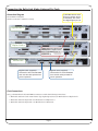
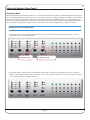
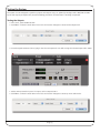
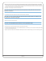
www.solidstatelogic.com
XLogic Delta-Link / Alpha-Link / Digidesign Pro Tools®
Get started quickly with a Delta-Link, Alpha-Link and Pro Tools combination
Setup Guide
V1.0
XLogic. This is SSL.
Document History
November 2009
V1.0
Initial Release
Contents
Introduction
1
Connecting the Delta-Link, Alpha-Links and Pro Tools
2
Connection Diagram
2
Clock Connections
2
MADI Connections
3
Digilink Connections
3
Power Connections
3
Alpha-Link Settings (Front Panel)
Connection Mode
WordClock
4
4
6
External Clock Source
6
Internal Clock Source
6
Audio I/O Routing
7
Getting Audio into Pro Tools
7
Getting Audio out of Pro Tools
7
Powering up the Delta-Link and Pro Tools System
8
Delta-Link Settings (Controlled from the Pro Tools Software)
8
Pro Tools Menu: Setup | Hardware
Pro Tools Menu: Setup I/O
Testing the System
8
10
13
Testing the Outputs
13
Testing the Inputs
15
Introduction
While the Delta-Link and Alpha-Link documentation provides detailed information about their respective features and
settings, this setup guide is intended to help you get started quickly with a Pro Tools, Delta-Link and Alpha-Link combination.
It would be impossible to describe every possible setting for every possible hardware configuration at all sample rates,
etc… so as an example we will focus on a system that includes:
• One Digidesign Pro Tools® HD2 system
• One SSL Delta-Link
• Two SSL Alpha-Links
Pro Tools 8 was used when writing this Setup Guide. The information therein also applies to Pro Tools 7
We want to set the system up to provide 64 inputs and outputs at 44.1 or 48kHz (24 Analogue and 8 AES/EBU or ADAT
inputs and outputs per Alpha-Link).
Please follow this guide to get started before moving on to more advanced settings, should you require them.
Page 1
Connecting the Delta-Link, Alpha-Links and Pro Tools
Connection Diagram
75 Ohm WordClock cable
from clock master device
(if available). This could
be a Digidesign Sync I/O.
Clock, MADI and Digilink
(Power connections omitted for clarity)
Alpha-Link 1
Alpha-Link 2
MADI cable pairs (Delta-Link
MADI port A to Alpha-Link 1,
Delta-Link MADI port B to
Alpha-Link 2)
Delta-Link
Digilink cable (supplied)
connected to Pro Tools HD CORE
card. Use the cable provided for
correct operation.
Digilink cable (supplied)
connected to Pro Tools HD ACCEL
card. Use the cable provided for
correct operation.
Clock Connections
Use 75 ohm WordClock cable with BNC connectors to make the following connections:
• WordClock Out from clock master device (e.g. Digidesign Sync I/O) to WordClock In of Alpha-Link 1
• WordClock Out from Alpha-Link 1 to WordClock In of Alpha-Link 2
• WordClock Out from Alpha-Link 2 to WordClock In of Delta-Link
Page 2
MADI Connections
Use 50/125 µm multimode fibre cables with SC connectors to make the following connections:
• Alpha-Link 1 MADI to Delta-Link MADI port A
• Alpha-Link 2 MADI to Delta-Link MADI port B
MADI cables are normally paired, and the input and output connectors at each end are keyed and linked, so that it is
almost impossible to insert them the wrong way around into the MADI head. The connectors may also be marked or
colour-coded to distinguish cable 1 from cable 2. However, if the connectors are not linked, it is possible to insert them the
wrong way around! Please be especially careful if you use non-paired cables.
Digilink Connections
Use the supplied Digilink cables to make the following connections:
• Delta-Link primary port A to Pro Tools HD Core card
• Delta-Link primary port B to Pro Tools HD Accel card
The maximum allowable length of the DigiLink cables varies as follows according to the Sample rate being used:
• 192 kHz operation: 45 cm (1.5')
• 96 kHz operation: 90 cm (3')
• 48 kHz operation: 180 cm (6')
IMPORTANT
The 90 cm cables supplied by SSL can only be used at up to 96kHz! In this setup guide we are
configuring the system for 44.1 or 48kHz, so this limitation is not relevant. But make sure you
take it into account if you work at 192kHz later.
Power Connections
The Alpha-Links, Delta-Link and Pro Tools computer must also be connected to the mains power. However, please do not
power them up at this point. We want to start the Alpha-Links in diagnostics mode to change their connection mode,
which requires a special routine (useful to know if you want to change global settings later).
We’ll start the Delta-Link and Pro Tools system when the Alpha-Links are ready.
Page 3
Alpha-Link Settings (Front Panel)
Connection Mode
By default, MADI input and output channels 1 to 24 of the Alpha-Link will be routed to its AES/EBU or ADAT outputs and
inputs, while MADI input and output channels 25 to 48 will be routed to its Analogue outputs and inputs. In this example
we want the Analogue inputs and outputs to be routed to the lower numbered MADI channels (as is the preference in
many studios), while the AES/EBU or ADAT inputs and outputs will be routed to the higher numbered MADI channels. This
means we have to change the ‘connection mode’, and this must be done in the Alpha-Link’s ‘diagnostics mode’.
This must be done on both Alpha-Links
1. Hold down the Clock and Sample Rate buttons for a few seconds while powering up the Alpha-Link, to start in
Diagnostics mode. The XS LED will flash.
Press and hold
while powering up
XS LED flashes to indicate
Diagnostics mode
2. By default, Option Switch 1 will be selected (indicated by LED 17 being lit in the Metering section). Pressing the
Meters button toggles between Option Switches 1 and 2, but you will not need to use it in this case (the connection
mode setting is Option 4 of Option Switch 1).
Page 4
3. Press the Output button three times to select Option 4 (indicated by LED 12 being lit in the Metering section).
Press repeatedly
Option 4 selected
4. Press the Input button to change the connection mode (LED 4 will be turned off ).
Option 4 status changes
Press
5. Press and release the Sample Rate and Clock buttons again to return to normal operation and save the new setting
(if you just power off the new setting will be lost). Now the Analogue inputs will be connected to the lower numbered
MADI channels.
Many other Alpha-Link parameters can be set in diagnostics mode: MADI mode (64 or 56 channels), SMUX mode
on or off for MADI, ADAT or AES/EBU, sample rate conversion on or off for AES/EBU, clock source for external
clock (MADI or WordClock), to name a few. Details are provided in the Alpha-Link User Guide.
Page 5
WordClock
At this point the connection mode has been set, and you should have returned the Alpha-Link to normal operation by
exiting diagnostics mode. You can move on to the clock and routing settings.
External Clock Source
If you have connected your Alpha-Links according to our connection diagram using an external clock
master device, both Alpha-Links are synchronized to an external source:
• The external clock source must be set to provide a 44.1 or 48kHz clock signal (as required for the
configuration in this example)
• Alpha-Link 1 receives the reference clock signal from the clock master device
• Alpha-Link 2 receives the clock signal from Alpha-Link 1
Both Alpha-Links therefore need to be set to ‘External’. To do this, simply press the CLOCK button
repeatedly until the EXT LED is lit.
This must be done on both Alpha-Links
Internal Clock Source
If you have chosen to use Alpha-Link 1 as a clock source for Alpha-Link 2 (typically, if you do not have a dedicated master
clock device):
• Alpha-Link 1 must be set to ‘Internal’ to lock to its on-board clock generator
• Alpha-Link 1 must also be set to 44.1 or 48kHz by pressing the SAMPLE RATE button (as required for the
configuration in this example)
• Alpha-Link 2 will receive the clock signal from Alpha-Link 1
Press the Alpha-Link 1 CLOCK button repeatedly until the INT LED is lit, then press the Alpha-Link 2 CLOCK button
repeatedly until the EXT LED is lit.
Alpha-Link 1
Alpha-Link 2
Page 6
Audio I/O Routing
Getting Audio into Pro Tools
Analogue and Digital inputs to MADI outputs:
In order to receive external signals in Pro Tools, the Alpha-Links’ Analogue and Digital
(AES/EBU or ADAT) inputs need to be routed to the Alpha-Link MADI outputs (the signals
will then reach the Delta-Link MADI inputs).
• Press the OUTPUT button repeatedly until the MADI output LED is lit, then hold
it down
• While holding the OUTPUT button, press the INPUT button repeatedly until the AES
or ADAT and ANA LEDs are lit
This must be done on both Alpha-Links
Getting Audio out of Pro Tools
In order to play back signals from Pro Tools, the Alpha-Links’ MADI inputs need to be
routed to the Alpha-Link Analogue and Digital (AES/EBU or ADAT) outputs.
MADI inputs to digital (AES/EBU or ADAT) outputs:
• Press the OUTPUT button repeatedly until the AES or ADAT output LED is lit, then
hold it down
• While holding the OUTPUT button, press the INPUT button repeatedly until the
MADI LED is lit
This must be done on both Alpha-Links
MADI inputs to Analogue outputs:
• Press the OUTPUT button repeatedly until the ANA output LED is lit, then hold it down
• While holding the OUTPUT button, press the INPUT button repeatedly until the
MADI LED is lit
This must be done on both Alpha-Links
Page 7
Powering up the Delta-Link and Pro Tools System
At this point you can start up the Delta-Link and Pro Tools computer and the Pro Tools software. However, do not load a
session with a different sample rate from the one received by the Alpha-Links and Delta-Link. The Delta-Link expects to
receive a clock signal at the sample rate determined by the session. If a session is opened at a different sample rate from
the current one, the Delta-Link Clock LED will flash until a clock signal at the appropriate sample rate is received. The
clock source in Pro Tools must also be set to ‘Internal’ for the first 192 unit (more about this later).
The settings and/or descriptions in this setup guide are applicable for a session at 44.1 or 48kHz only.
Delta-Link Settings (Controlled from the Pro Tools Software)
Pro Tools Menu: Setup | Hardware
Click ‘Hardware’ in the Pro Tools Setup menu to make the settings described in the following diagrams. First, check that
the Delta-Link is recognized as four Digidesign 192 units and set the Clock Source as described below.
1. Make sure you see four
192 peripherals. If not, check
the Digilink connections.
2 . The ‘Clock Source’ must be the first 192 unit (indicated by the dot in
front of its name), and must always be set to ‘Internal’ (indicated by the
tick), even though you may be using an external clock master device. In
reality the Delta-Link is always clocked externally, but the Pro Tools
software has no ‘knowledge’ of the Delta-Link.
Page 8
Output Trim settings are irrelevant to the Delta-Link because its inputs and outputs are all digital. We can therefore use
the Analog Out tab of the Pro Tools software’s Hardware Setup window to control internal Delta-Link settings.
4. Click the Analog Out tab, then apply the following settings:
• Set Ch 1 to ‘A’ to match the Alpha-Links setting, which defaults to 56
MADI channels (or see the manual to switch the Alpha-Links to 64 MADI
channels).
3. Make sure the first 192 is
selected while you change
settings, as the Delta-Link is
controlled via Primary Port A.
• Set Ch 2 to ‘B’. This selects the Delta-Link ‘Special Mode’, so that each
primary port is linked to one MADI port (in ‘Normal Mode’, the output
signals from both the Core and Accel cards would be duplicated on the
outputs of both Alpha-Links, but the signals received on the Alpha-Link
2 inputs would not reach Pro Tools!)
• Ch 3 to Ch 8 should be set to ‘A’.
5. When ready, click OK to exit the
Hardware Setup and save your settings.
Page 9
Pro Tools Menu: Setup I/O
Click ‘I/O’ in the Pro Tools Setup menu to make the settings described in this section.
Each Digidesign 192 unit provides 16 inputs and outputs. Therefore the first two 192 units in Pro Tools correspond
with Delta-Link primary port A and Alpha-Link 1, and the last two 192 units with Delta-Link primary port B and
Alpha-Link 2 (28 or 32 input and output channels down each Digilink cable, depending on MADI channel count).
2. Delete any existing audio paths by
selecting them in the column on the left
and clicking the Delete Path button.
Then create new default one-to-one paths
by pressing the Default button.
1. Make sure you see four 192
peripherals in the top row. If not,
check the Digilink connections.
Page 10
3. Think of the first two 192 units as one giant 32 channel 192. The first 24 inputs are Analogue inputs
1-24 of Alpha-Link 1. The last 8 are AES/EBU or ADAT inputs 1-8 of Alpha-Link 1.
For the other two 192 units, the first 24 inputs are Analogue inputs 1-24 of Alpha-Link 2 (analogue
inputs 25-48 of the system). The last 8 are AES/EBU or ADAT inputs 1-8 of Alpha-Link 2 (AES/EBU or
ADAT inputs 9 to 16 of the system).
In the column on the left hand side you can name the inputs as required.
4. Click the Output tab and make the
same changes for the outputs as you
have made for the inputs (delete any
existing paths, create default paths,
name the outputs as required).
5. When ready, click OK to exit the
I/O Setup and save your settings
Page 11
In our example Pro Tools inputs/outputs A1-B8 are ANA 1-24 of Alpha-Link 1, and Pro Tools B9-B16 are AES or ADAT
1-8 of Alpha-Link 1. Pro Tools C1-D8 are ANA 1-24 of Alpha-Link 2, and Pro Tools D9-D16 are AES or ADAT
1-8 of Alpha-Link 2. If you prefer to have all the Analogue inputs/outputs of both Alpha-Links listed first, followed
by the all the AES/EBU or ADAT of both Alpha-Links, select A9-B16 and B9-B16 in the left-hand side column and
click the Delete Path button. Then click the Default button again. The deleted paths will reappear at the bottom of
the list. The ‘first’ 48 inputs/outputs will be Analogue, and the ‘last’ 16 will be AES/EBU or ADAT. When you create
64 tracks in the Pro Tools mixer and increment the outputs, you will have all the Analogue on the left and all the
AES/EBU or ADAT on the right. Click the Settings button if you want to save this configuration so that you can
reload it later, for example when loading a session from another studio.
Page 12
Testing the System
The system is now configured to provide 64 inputs and outputs at 44.1 or 48kHz (24 Analogue and 8 AES/EBU or ADAT
inputs and outputs per Alpha-Link). Use the following procedures to check that it is working as expected.
Testing the Outputs
• In Pro Tools, open the Mix window
• Click ‘New…’ under the Track menu in Pro Tools and use the dialogue to create one Aux Input track
• Insert the Signal Generator (mono) plug-in into the aux input track. You will see signal in the Aux Input track’s meter
• Set the Aux Input track’s input to ‘no input’, and its output to Bus 1
• Click ‘New…’ under the Track menu in Pro Tools and use the dialogue to create 64 mono audio tracks
Page 13
• Make sure all the audio tracks are selected (not the aux input track!), so that the following changes can be applied
to audio tracks only. The track names should be highlighted to indicate that they are selected, which should be the
case just after they have been created. Otherwise, press and hold the Shift key (PC or Mac) and click the name field
of the first and last tracks to select the whole track range.
• Select Bus 1 as the input source for all audio tracks
On PC, Shift + Alt + click one of the selected audio tracks’ input button. On Mac, Shift + Alt + click one of the
input buttons. Select Bus 1.
• Increment the audio track outputs (the audio tracks must still be selected)
On PC, Shift + Ctrl + Alt + click the output button of the first audio track. On Mac, Shift + Alt + Command + click
the output button. Select the first output path.
• Monitor the inputs of all audio tracks
On PC, Alt + click an Input Monitor button. On Mac, Alt + click an Input Monitor button.
• At this point, you should see signal in the Pro Tools audio track meters
• On the front panel of the Alpha-Link, press the METERS button to select D/A, you should see the metering LEDs light
up as they are receiving the signal
• Signals output via the Alpha-Link’s AES/EBU or ADAT outputs must be checked through your audio monitoring system
Page 14
Testing the Outputs
Audio track inputs set to Bus 1
(to receive signal from the
Signal Generator plug-in
inserted in the aux track)
Partial view of the Pro Tools Mixer
Signal Generator plug-in
Aux track input
(no input selected)
Aux track output (Bus
1 selected to feed the
audio tracks)
Audio track outputs (incremented
to transmit signal to the first 32
channels of each Alpha-Link. The
names will be different if you have
renamed the audio paths)
Input Monitor buttons
(input monitoring
must be on)
Testing the Inputs
The procedure to test the inputs depends largely on your available sound sources.
Essentially, you need to connect sound sources to the Analogue and AES/EBU or ADAT inputs of both Alpha-Links, set
Pro Tools tracks to use the corresponding audio paths as inputs, and monitor the incoming signals. The inputs can be
tested individually, or several can be tested at the same time, depending on the external sound sources available to you.
You can also connect the outputs of Alpha-Link 1 to the inputs of Alpha-Link 2, and check that signals output from
Pro Tools via Alpha-Link 1 are received back via Alpha-Link 2 (the track inputs and outputs need to be set accordingly in
Pro Tools). Then the same test can be carried out the other way around.
Page 15
Visit SSL at: www.solidstatelogic.com
© Solid State Logic
All Rights reserved under International and Pan-American Copyright Conventions
Alpha-Link and Delta-Link are trademarks of Solid State Logic
All other product names and trademarks are the property of their respective owners and are
hereby acknowledged
No part of this publication may be reproduced in any form or by any means, whether mechanical
or electronic, without the written permission of Solid State Logic, Oxford, OX5 1RU, England
As research and development is a continual process, Solid State Logic reserves the right to
change the features and specifications described herein without notice or obligation.
Solid State Logic cannot be held responsible for any loss or damage arising directly or indirectly
from any error or omission in this manual.
E&OE