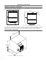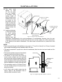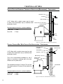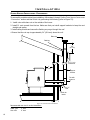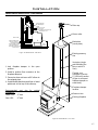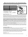
1
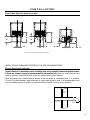
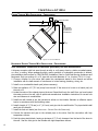
PLEASE KEEP THESE INSTRUCTIONS FOR FUTURE REFERENCE PELLET STOVE DAVENPORT Freestanding and Fireplace Insert OWNER’S MANUAL Contact your building or fire officials about restrictions and installation inspection requirements in your area. PLEASE READ THIS ENTIRE MANUAL BEFORE INSTALLATION AND USE OF THIS PELLET-BURNING ROOM HEATER. FAILURE TO FOLLOW THESE INSTRUCTIONS COULD RESULT IN PROPERTY DAMAGE, BODILY INJURY OR EVEN DEATH. 16621 THIS MANUAL IS PRINTED ON RECYCLED PAPER. 50-2322 Table of Contents introduction .............................................................................................................3 rating pellet label location................................................................................................3 quality............................................................................................................3 important safety data..................................................................................................4 safety dimensions & warnings and recommendations...........................................................................4 specifications......................................................................................................6 dimensions dimensions - freestanding............................................................................................6 fireplace insert.......................................................................................6 s p e c i f i c at i o n s .....................................................................................6 i n s ta l lat i o n .................................................................................................7 deciding where to locate your pellet appliance................................................................7 removing your pellet stove from the pallet......................................................................7 clearances to combustibles alcove clearances - - freestanding.........................................................................8 - fireplace insert....................................................................9 freestanding....................................................................................8 clearances to combustibles mobile home installation - freestanding...........................................................................9 vent termination requirements.....................................................................................10 exhaust and fresh air intake locations............................................................................11 outside fresh air connection.......................................................................................11 corner through wall installation - freestanding..............................................................12 horizontal exhaust through wall installation - freestanding...............................................12 - freestanding (recommended)...........14 - freestanding.....................................14 inside vertical installations - freestanding........................................................................15 outside vertical installations - freestanding...................................................................16 hearth mount installation - freestanding.......................................................................17 masonry fireplace installation - fireplace insert...............................................................18 positive flue connection without a full reline - fireplace insert (usa only)..........................19 installation of the control panel in the surround panel - fireplace insert...............................20 installation of insert surround panel - fireplace insert......................................................20 thermostat installation..............................................................................................21 slider/damper set-up..................................................................................................21 operating instructions.........................................................................................................22 control board functions...........................................................................................22 automatic safety features of your pellet stove............................................................22 operating your pellet stove......................................................................................22 turning your pellet stove off.....................................................................................23 adjusting the vacuum using the slider/damper..................................................................24 guidelines for fine-tuning for fuel quality..............................................................24 routine cleaning and maintenance..........................................................................................25 t r o u b l e s h o ot i n g .......................................................................................28 wiring diagram....................................................................................................................31 parts diagram fs....................................................................................................................32 parts diagram fpi...................................................................................................................33 parts diagram options............................................................................................................34 parts list............................................................................................................................35 warranty ................................................................................................................37 installation data sheet.........................................................................................................38 vertical rise with horizontal termination installation through concrete wall with vertical rise installation 2 Introduction Rating Label Location: Freestanding: The rating label is located on the inside of the hopper lid. Insert: The rating label is located on the hopper cover. Pellet Quality: Pellet quality is important, please read the following: Your Hudson River pellet stove has been designed to burn wood pellets only. Do not use any other type of fuel, as this will void any warranties stated in this manual. The performance of your pellet stove is greatly affected by the type and quality of wood pellets being burned. As the heat output of various quality wood pellets differs, so will the performance and heat output of the pellet stove. Caution: It is important to select and use only pellets that are dry and free of dirt or any impurities such as high salt content. Dirty fuel will adversely affect the operation and performance of the unit and will void the warranty. The Pellet Fuel Industries (P.F.I.) has established standards for wood pellet manufacturers. We recommend the use of pellets that meet or exceed these standards. Ask your dealer for a recommended pellet type. P.F.I. PELLET STANDARDS: Fines (fine particles)......1% maximum through a ⅛” screen Bulk Density..................40 pound per cubic foot minimum Size..............................¼” to 5/16” diameter ½ – 1½” long maximum Ash Content..................1% maximum (Premium grade) ..................3% maximum (Standard grade) Moisture Content...........8% maximum Heat Content.................approximately 8200 Btu per pound minimum ASH: The ash content of the fuel and operation of your stove will directly determine the frequency of cleaning. The use of high ash fuels may result in the stove needing to be cleaned daily. A low ash fuel may allow longer intervals between cleaning. CLINKERING: Clinkers are silica (sand) or other impurities in the fuel that will form a hard mass during the burning process. This hard mass will block the air flow through the Burn Pot Liner and affect the performance of the stove. Any fuel, even approved types, may tend to clinker. Check the Burn-Pot Liner daily to ensure that the holes are not blocked with clinkers. If they become blocked, remove the liner (when the unit is cold) and clean/scrape the clinkers out. Clean the holes with a small pointed object if required. Refer to the Routine Cleaning and Maintenance section of this manual. PELLET FEED RATES: Due to different fuel densities and sizes, pellet feed rates may vary. This may require an adjustment to the slider damper setting or to the auger feed trim setting on low heat levels. Since Hudson River Stove Works has no control over the quality of pellets that you use, we assume no liability for your choice in wood pellets. Store pellets at least 36” (1 m) away from the pellet stove. 3 Introduction Important Safety Data: Please read this entire Owner’s Manual before installing or operating your HUDSON RIVER Pellet Stove. Failure to follow these instructions may result in property damage, bodily injury or even death. Contact your local building or fire official to obtain a permit and any information on installation restrictions and inspection requirements for your area. To prevent the possibility of a fire, ensure that the appliance is properly installed by adhering to the installation instructions. A HUDSON RIVER dealer will be happy to assist you in obtaining information with regards to your local building codes and installation restrictions. Be sure to maintain the structural integrity of the home when passing a vent through walls, ceilings, or roofs. The stove’s exhaust system works with negative combustion chamber pressure (vacuum) and a slightly positive chimney pressure. It is very important to ensure that the exhaust system be sealed and airtight. The ash pan and viewing door must be locked securely for proper and safe operation of the pellet stove. Do not burn with insufficient combustion air. A periodic check is recommended to ensure proper combustion air is admitted to the combustion chamber. Setting the proper combustion air is achieved by adjusting the slider damper located on the left side of the stove. When installing the stove in a mobile home, it must be electrically grounded to the steel chassis of the home and bolted to the floor. Make sure that the structural integrity of the home is maintained and all construction meets local building codes. Minor soot or creosote may accumulate when the stove is operated under incorrect conditions such as an extremely rich burn (black tipped, lazy orange flames). If you have any questions with regard to your stove or the above-mentioned information, please feel free to contact your local dealer for further clarification and comments. Safety Warnings And Recommendations: Caution: Do not connect to any air distribution duct or system. Do not burn garbage or flammable fluids such as gasoline, naptha or engine oil. Unit hot while in operation. Keep children, clothing and furniture away. Contact may cause skin burns. FUEL: This pellet stove is designed and approved to only burn wood pellet fuel with up to 3% ash content. Dirty fuel will adversely affect the operation and performance of the unit and may void the warranty. Check with your dealer for fuel recommendations. THE USE OF CORDWOOD IS PROHIBITED BY LAW. SOOT: Operation of the stove with insufficient combustion air will result in the formation of soot which will collect on the glass, the heat exchanger, the exhaust vent system, and may stain the outside of the house. This is a dangerous situation and is inefficient. Frequently check your stove and adjust the slider/ damper as needed to ensure proper combustion. See: “Adjusting the vacuum using the slider/damper”. CLEANING: There will be some build up of fly ash and small amounts of creosote in the exhaust. This will vary due to the ash content of the fuel used and the operation of the stove. It is advisable to inspect and clean the exhaust vent semi-annually or every two tons of pellets. 4 Introduction ASHES: Disposed ashes should be placed in a metal container with a tight fitting lid. The closed container of ashes should be stored on a non-combustible floor, well away from all combustible materials pending final disposal. If the ashes are disposed of by burial in soil or otherwise locally dispensed, they should be retained in the closed container until all cinders have been thoroughly cooled. ELECTRICAL: The use of a surge protected power bar is recommended. The unit must be grounded. The grounded electrical cord should be connected to a standard 115 volts (3.3 Amps), 60 hertz electrical outlet. Be careful that the electrical cord is not trapped under the appliance and that it is clear of any hot surfaces, sharp edges, and is accessible. If this power cord should become damaged, a replacement power cord must be purchased from the manufacturer or a qualified HUDSON RIVER dealer. This unit’s maximum power requirement is 400 watts. GLASS: Do not abuse the glass by striking or slamming the door. Do not attempt to operate the stove with broken glass. The stove uses ceramic glass. Replacement glass must be purchased from an HUDSON RIVER dealer. Do not attempt to open the door and clean the glass while the unit is in operation or if glass is hot. To clean the glass, use a soft cotton cloth and mild window cleaner, gas or wood stove glass cleaner, or take a damp paper towel and dip into the fly ash. This is a very mild abrasive and will not damage the glass. FLAMMABLE LIQUIDS: Never use gasoline, gasoline-type lantern fuel, kerosene, charcoal lighter fluid, or similar liquids to start or “freshen up” a fire in the heater. Keep all such liquids well away from the heater while it is in use. SMOKE DETECTOR: Smoke detectors should be installed and maintained in the structure when installing and operating a pellet burning appliance. OPERATION: The ash pan, door, and hopper lid must be closed securely for proper and safe operation of the pellet stove. Ensure all gaskets and seals are checked regularly and replaced when necessary. KEEP ASH PAN FREE OF RAW FUEL. DO NOT PLACE UNBURNED OR NEW PELLET FUEL IN THE ASH PAN. A FIRE IN THE ASH PAN MAY OCCUR. INSTALLATION: Be sure to maintain the structural integrity of your home when passing a vent through walls, ceilings, or roofs. It is recommended that the unit be secured into its position in order to avoid any displacement. DO NOT INSTALL A FLUE DAMPER IN THE EXHAUST VENTING SYSTEM OF THIS UNIT. DO NOT CONNECT THIS UNIT TO A CHIMNEY FLUE SERVING ANOTHER APPLIANCE. FRESH AIR: Outside Fresh Air connection is optional BUT MUST be connected to all units installed in Mobile and “Air Tight Homes” (R2000) or where required by local codes. Consider all large air moving devices when installing your unit and provide room air accordingly. Limited air for combustion may result in poor performance, smoking and other side effects of poor combustion. If you have any questions with regards to your stove or the above-mentioned information, please feel free to contact your local dealer for further clarification and comments. Since HUDSON RIVER STOVE WORKS has no control over the installation of your stove, HUDSON RIVER STOVE WORKS grants no warranty implied or stated for the installation or maintenance of your stove. Therefore, HUDSON RIVER STOVE WORKS assumes no responsibility for any consequential damage(s). SAVE THIS INSTRUCTION MANUAL FOR FUTURE REFERENCE 5 Specifications Dimensions - Freestanding: 1 26 2 " 1 22 4 " 1 33 2 " 3 34 16 " 5 20 8 " 3 21 8 " 20" Dimensions - Fireplace Insert: Figure 1: Davenport Freestanding Dimensions. 25 58 " 22" 5 14 8 " 22 34 " Specifications: Figure 2: Davenport Fireplace Insert Dimensions. Input rating: 42,500BTU Table 1: Davenport Specifications. Description Residential Pellet Heater Fuel type 6mm (¼”) dia. Wood Pellets Voltage 110 - 120 V Current 3.3 Amps Max Power 400 Watts Frequency 60 Hz Hopper Capacity FS / FPI 60 lbs / 40 lbs Consumption on Low 1.5 lb/hr Testing Standard ASTM 1509-04 Weight** FS Ped/ FS Legs / FPI 290 lbs / 300 lbs / 250 lbs Consumption on High 5 lb/hr *Consumption will vary with the type of fuel used. 6 **With Full Hopper. Installation Deciding Where to Locate your Pellet Appliance: 1. Check clearances to combustibles (see Installation - Clearances to Combustibles - Freestanding, Installation - Alcove Clearances - Freestanding, and Installation Clearances to Combustibles - Fireplace Insert. 2. Do not obtain combustion air from an attic, garage or any unventilated space. Combustion air may be obtained from a ventilated crawlspace. 3. Do not install the stove in a bedroom. 4. You can vent the stove through an exterior wall behind the unit or connect it to an existing masonry or metal chimney (must be lined if the chimney is over 6” (15 cm) diameter, or over 28 inches² (180 cm²) cross sectional area). An interior vent can be used with approved pipe passing through the ceiling and roof. 5. Locate the stove in a large and open room that is centrally located in the house. This will optimize heat circulation. 6. The power cord is 8 feet (2.43 m) long and may require a grounded extension cord to reach the nearest electrical outlet. Removing Your Pellet Stove From the Pallet: To remove your new stove from its pallet, remove the two (2) screws securing the bottom to the pallet. Freestanding: 1. Remove access cover from front of unit. 2. Remove the two (2) T-20 Torx screws each side holding the cabinet sides closed. 3. Open the side cabinets. The screw holding the unit to the pallet are now accessible. Fireplace Insert: 1. The screws are accessible from the back side of the unit. Figure 3: Removing Freestanding Stove From the Pallet. 7 Installation Clearances to Combustibles - Freestanding: These dimensions are minimum clearances but it is recommended that you ensure sufficient room for servicing, routine cleaning, and maintenance. Back wall 2" Adjacent wall Side wall 2" 6" 9” MINIMUM Figure 4: Davenport on Floor Protection. Figure 5: Minimum Clearances to Combustibles for Freestanding Davenport. This pellet stove requires floor protection. The floor protection must be non-combustible, extending beneath the stove the full width and depth of the unit including 9“ in front for ember protection. Alcove Clearances - Freestanding: Minimum Width 36" Minimum Height 48" Maximum Depth 30" Figure 6: Alcove Clearances Freestanding Davenport. 8 Installation Clearances to Combustibles - Fireplace Insert: The fireplace insert must be installed into a masonry fireplace. This model includes a surround faceplate and a pedestal. From the body of the heater to the side wall: 9 inches minimum From the body of the heater to the Facing on masonry fireplace: 8 inches minimum From the body of the heater to the 10” (203 mm) mantle: 8 inches minimum Mobile Home Installation - Freestanding: ● Secure the heater to the floor using the holes in the pedestal of the appliance. ● Ensure the unit is electrically grounded to the chassis of your home (permanently). WARNING: Do not install in a room people sleep in. CAUTION: The structural integrity of the manufactured home floor, wall and ceiling/roof must be maintained • Outside fresh air is mandatory. Secure outside air connections directly to fresh air intake pipe and secure with three (3) screws evenly spaced. Hearth Pad Flooring Steel Frame 1/4" Lag bolts securely fastened Ground wire directly connected to metal chassis. Figure 7: Mobile Home Install Mounting. 9 Installation Vent Termination Requirements: IT IS RECOMMENDED THAT YOUR PELLET STOVE BE INSTALLED BY AN AUTHORIZED DEALER/INSTALLER. Table 2: Use in conjunction with Figure 13 for allowable exterior vent termination locations. Letter Minimum Clearance Description A 24 in (61 cm) B 48 in (122 cm) Above grass, top of plants, wood, or any other combustible materials. C 12 in (30 cm) Above any door or window that may be opened. (9” (23 cm) if outside fresh air installed.) D 24 in (61 cm) To any adjacent building, fences and protruding parts of the structure. E 24 in (61 cm) Below any eave or roof overhang F 12 in (30 cm) To outside corner. To inside corner, combustible wall (vertical and horizontal terminations). From beside/below any door or window that may be opened. G 12 in (30 cm) H 3 ft (91 cm) within a height of 15 ft (4.5 m) above the meter/ regulator assembly I 3 ft (91 cm) J 12 in (30 cm) Clearance to non-mechanical air supply inlet to building, or the combustion air inlet to any appliance. K 24 in (61 cm) Clearance above roof line for vertical terminations. L 7 ft (2.13 m) Clearance above paved sidewalk or paved driveway located on public property. 1.Do not terminate the vent in any enclosed or semi-enclosed areas such as a carport, garage, attic, crawlspace, narrow walkway, closely fenced area, under a sundeck or porch, or any location that can build up a concentration of fumes such as stairwells, covered breezeway, etc. To each side of center line extended above natural gas or propane meter/ regulator assembly or mechanical vent. From any forced air intake of other appliance G K E D F B Opens G Opens B A Termination Cap Air Supply Inlet G C I G Gas Meter Opens Restriction Zone L H (Termination not allowed) Figure 8: Use in conjunction with Table 1 for allowable exterior vent termination locations. 2.Vent surfaces can become hot enough to cause burns if touched by children. Non-combustible shielding or guards may be required. 3.Termination must exhaust above the inlet elevation. It is recommended that at least five feet of vertical pipe be installed outside when the appliance is vented directly through a wall, to create some natural draft to prevent the possibility of smoke or odor during appliance shut down or power failure. This will keep exhaust from causing a nuisance or hazard from exposing people or shrubs to high temperatures. In any case, the safest and preferred venting method is to extend the vent through the roof vertically. 4.Distance from the bottom of the termination and grade is 12” (30 cm) minimum. This is conditional upon the plants and nature of grade surface. The exhaust gases are hot enough to ignite grass, plants and shrubs located in the vicinity of termination. The grade surface must not be lawn. 5.If the unit is incorrectly vented or the air to fuel mixture is out of balance, a slight discoloration of the exterior of the house might occur. Since these factors are beyond the control of Hudson River Stove Works, we grant no guarantee against such incidents. 10 NOTE: Venting terminals shall not be recessed into walls or siding. Installation Exhaust And Fresh Air Intake Locations: 1 16 2 " 3 10 4 " 1" 1 17 8 " 3 11 8 " 3 54" 1" 3 54" 3 38" 3 54" 1" 1 98" Figure 9: Davenport Inlet and Outlet Location. INSTALL VENT AT CLEARANCES SPECIFIED BY THE VENTING MANUFACTURER Outside Fresh-Air Connection: Outside fresh air is mandatory when installing this unit in airtight homes and mobile homes. A Fresh-air intake is strongly recommended for all installations. Failure to install intake air may result in improper combustion as well as the unit smoking during power failures. When connecting to an outside fresh air source, do not use plastic or combustible pipe. A 2” minimum (51 mm) ID (inside diameter) steel, aluminum or copper pipe should be used. It is recommended, when you are installing a fresh air system, to keep the number of bends in the pipe to a minimum. Outside Wall 2" ID (51 mm) Optional Elbow Figure 11: Outside Air Connection. 11 Installation Corner Through Wall Installation - Freestanding: Fresh Air Intake 3" (7.5 cm) Wall thimble manufactured by pellet vent manufacturer. 3" (7.5 cm) Figure 12: Corner Installation. Horizontal Exhaust Through Wall Installation - Freestanding: Vent installation: install vent at clearances specified by the vent manufacturer. A chimney connector shall not pass through an attic or roof space, closet or similar concealed spaces, or a floor, or ceiling. Where passage through a wall or partition of combustible construction is desired, the installation shall conform to CAN/CSA-B365 Installation Code for Solid-Fuel-Burning Appliances and Equipment. Only use venting of L or PL type with an inside diameter of 3 or 4 inches (7.6 or 10.1 cm). 1. Choose a location for your stove that meets the requirements stated in this manual and allows installation with the least amount of interference to house framing, plumbing, wiring, etc. 2. Install a non-combustible hearth pad (where necessary). 3. Place the appliance 15” (37.5 cm) away from the wall. If the stove is to be set on a hearth pad, set the unit on it. 4. Locate the center of the exhaust pipe on the stove. Extend that line to the wall. Once you have located the center point on the wall, refer to pellet vent manufacturer installation instructions for correct hole size and clearance to combustibles. 5. Install the wall thimble as per the instructions written on the thimble. Maintain an effective vapour barrier in accordance with local building codes. 6. Install a length of 3” (76 mm) or 4” (101 mm) vent pipe into the wall thimble. The pipe should install easily into the thimble. 7. Install the fresh air intake (see Installation - Outside Fresh Air Connection). 8. Connect the exhaust vent pipe to the exhaust pipe on the stove. Seal the connection with high temperature silicone. 9. Push the stove straight back, leaving a minimum of 2” (5 cm) clearance from the back of the stove to the wall. Seal the vent pipe to the thimble with high temperature silicone. 12 Installation 10. The pipe must extend at least 12” (30 cm) away from the building. If necessary, bring another length of pipe (PL type) to the outside of the home to connect to the first section. Do not forget to place high temperature silicone around the pipe that passes through the thimble. Exhaust Tube 3" (75mm) or 4" (100mm) "PL" or "L" vent Wall Thimble 45° Elbow with screen or Termination Cap 11. Install a vertical pipe, or if all requirements for direct venting Fresh Air Intake High Temperature RTV are met, install vent Silicone Required termination. The Figure 13: Straight through wall Installation. stainless steel cap termination manufactured by the vent manufacturer is recommended. However, when the vent terminates several feet above ground level and there are no trees, plants, etc. within several feet, a 45° elbow can be used as termination. The elbow must be turned down to prevent rain from entering. NOTE: • Some horizontal through wall installations may require a “T” and 3 to 5 feet (91 to 152 cm) of vertical pipe outside the building to help naturally draft in the unit. • This may be required if a proper burn cannot be maintained, after the stove has been tested and the airflow set. • This is due to the back pressure in the exhaust caused by airflow around the structure. • All sections of pipe must have three (3) screws evenly spaced and all horizontal and vertical vent sections located within the house must have a bead of high temperature silicone installed on the male end of the pipe before installation to create a gas tight seal. • The termination must be 12 inches (30 cm) from the outside wall and 12 inches (30 cm) above the ground. • A 45° elbow with a rodent screen may be used in place of the termination cap (or stainless steel termination hood). Wall framing Horizontal frame for thimble Vent pipe Termination cap Wall thimble Figure 14: Straight through Wall Installation - Side View. 13 Installation veRticaL RiSe With hoRizontaL teRmination inStaLLation (RecommenDeD) - fReeStanDing: Termination cap 90°elbow Wall framing A 45° elbow with a rodent screen may be used in place of the termination cap (or stainless steel Vertical section of vent pipe termination hood). Horizontal frame for thimble Wall strap Recommended vent size for vertical installation: Under 15ft: 3” Vent Over 15ft: 4” Vent Clean out tee Wall thimble Figure 15: Through Wall with Horizontal Termination. thRough concRete WaLL With veRticaL RiSe inStaLLationS - fReeStanDing: Horizontal frame for thimble A 45° elbow with a rodent screen may be used in place of the termination cap (or stainless steel termination hood). Termination cap Wall thimble 90°elbow Wall framing This is the recommended installation to use if there is a concrete or retaining wall in line with exhaust vent on pellet stove. The termination must be 12 inches (30 cm) from the outside wall and 12 inches (30 cm) above the ground. Vertical section of vent pipe Concrete Wall Recommended vent size for vertical installation: Under 15ft: 3” Vent Over 15ft: 4” Vent Clean out tee Figure 16: Vertical rise with Horizontal Termination. 14 Installation Inside Vertical Installations - Freestanding: 1. Choose a stove location that is ideal. See the section “Installation - Deciding Where to Locate your Pellet Appliance.” 2. Place the unit on the hearth pad (if installed on a carpeted surface) and space the unit in a manner so when the pellet vent is installed vertically, it will be 3” (76 mm) away from a combustible wall. 3. Locate the center of the fresh air intake pipe on the unit. Match that center with the same point on the wall and cut a hole about 2” (51 mm) in diameter. Rain cap - ensure cap is at least 2 feet (610mm) above the roof at the lowest point Storm collar Roof flashing Roof rafter Fire stop with Support Collar Ceiling joist 4. Install the fresh air intake pipe. 5. Install the tee with clean out. 6. Install the pellet vent upward from there. When you reach the ceiling, make sure that the vent goes through the ceiling fire stop. Maintain a 3” (76 mm) distance to combustibles and keep attic insulation away from the vent pipe. Maintain an effective vapor barrier. Vertical vent pipe Clean out tee with Pipe adapter NOTE: All vent sections must maintain 3" (76 mm) clearances to combustibles. Unless otherwise specified by the vent manufacturer’s instructions. 7. Finally, extend the pellet vent to go through the roof flashing. 8. Ensure that the rain cap is approximately 24” (610 mm) above the roof. Figure 17: Inside Vertical Installation. Recommended vent size for vertical installation: Under 15ft: 3” Vent Over 15ft: 4” Vent 15 Installation Outside Vertical Installations - Freestanding: To accomplish a outside vertical pipe installation, follow steps 1 through 5 in the “Inside Vertical Installations - Freestanding” section and then finish it by performing the following (refer to Figure 23). 1. Install a tee with clean out on the outside of the house. 2. Install PL vent upward from the tee. Make sure that you install support brackets to keep the vent straight and secure. 3. Install ceiling thimble and secure the flashing as you go through the roof. 4. Ensure that the rain cap is approximately 24” (610 mm) above the roof. Rain cap Flashing 24" (61 cm) 3" (7.5 cm) Clearance 3" (7.5cm) Support bracket Tee with cleanout Type "L" vent Fresh air intake Figure 18: Outside Vertical Installation. Recommended vent size for vertical installation: 16 Under 15ft: 3” Vent Over 15ft: 4” Vent Installation Hearth Mount Installation - Freestanding: Damper Removed or Fastened Open Rain cap Mantel Minimum 8" (20 cm) from top of stove NOTE: Hopper lid will not open fully with less than 13.5”. Storm collar Clean-out tee Min 9" Fresh-air intake should come from chimney. If holes already exist fresh-air intake can be taken through back of the fireplace or through the ash dump. Floor Protection Masonry Fireplace Combustible Floor Figure 19: Hearth Mount - Side View. 1.Lock fireplace damper in the open position. 2.Install a positive flue connector at the fireplace dampers. 3.Connect a clean-out tee or a 90° elbow to the exhaust pipe. 4.Install flexible stainless steel liner or listed pellet vent to the top of the chimney. Recommended installation: vent Under 15ft: 3” Vent Over 15ft: 4” Vent size for Seal plate (cover plate) vertical Existing masonry flue Vent pipe (single wall stainless flex pipe or solid PL vent) Flexible vent connector (use this 5' [1520 mm] section of pipe to vent past fireplace damper or small shelf) Fireplace damper location Clean out tee Existing fireplace Figure 20: Hearth Mount - Over View. 17 Installation Masonry Fireplace Insert Installation - Fireplace Insert: The Fireplace insert model requires a surround faceplate and a pedestal. When installing this unit, ensure that the pedestal is removed from the inside of the hopper and installed on the bottom of the unit (Refer to Installation - Installation of Pedestal and Leveling Legs - Fireplace Insert). Adjust hopper height (see Installation - Installing Hopper Cover and Adjusting Hopper Height - Fireplace Insert) and assemble surround panel (see Installation - Installation and Removal of Control Panel in The Surround Panel - Fireplace Insert and Installation - Assembly and Installation of Insert Surround Panels - Fireplace Insert) before starting installation. Rain Cap A noncombustible hearth pad must cover combustible flooring underneath, as well as 9” in front of the heater and 6” to the side of the heater Fresh-air intake Steel Plate or Flashing Flexible or Rigid 6" Stainless Steel Liner 1. Install the hearth pad. 2.Lock the fireplace damper in the open position. 3.Install a positive flue connector at the fireplace damper. 4.Connect a tee or 90° degree elbow to the exhaust pipe. 5.This fireplace insert must be installed with a continuous chimney liner of 3 or 4” diameter extending from the fireplace insert to the top of the chimney. The liner must conform to type 3 requirements of CAN/ULC S635. 6.(Recommended) Install fresh air intake either through the back of the fireplace or through the positive flue connector. When installing the insert into a Damper Removed or Fastened Open Flexible stainless steel pipe connection Mantel Minimum 8" (20 cm) from top of stove Surround Panel Clean-out tee Min 9" If holes already exist fresh-air intake can be taken through the back of the fireplace or through the ash dump. Floor Protection Masonry Fireplace Combustible Floor Figure 21: Installation of Fireplace Insert. masonry fireplace DO NOT remove any bricks or masonry, with the following exception; masonry or steel, including the damper plate, may be removed from the smoke shelf and adjacent damper frame if necessary to accommodate a chimney liner. Provided that their removal will not weaken the structure of the fireplace and chimney, and will not reduce protection for combustible materials to less than that required by the national building code. When installing the fireplace insert into a zero clearance fireplace, DO NOT cut or modify any factory firebox parts. If the fireplace insert does not fit into a zero clearance fireplace we recommend you use an ENVIRO freestanding model and install as a hearth mounted unit. Install a 3” (76 mm) flex pipe from the stove to the top of the chimney (see “Installation - Hearth Mount Installation - Freestanding”). 18 Installation Positive Flue Connection without a Full Reline - Fireplace Insert (USA Only): This unit does not require a full reline (in USA only) when installing into a masonry fireplace, however, it is recommended to ensure proper drafting of the appliance. IMPORTANT: Ensure the chimney and firebox are cleaned and free of all debris, including soot and ashes, before proceeding with this installation. If it is not clean soot maybe blown into the room through the unit’s blower. Ensure the fireplace and chimney have not deteriorated in any way. If there is any sign of corrosion or damage in the chimney the unit can not be installed. This unit can be installing in a masonry fireplace built to (UBC 37 or ULC S628 standards) or a factory built fireplace (built to UL 127 or ULC S610 standards). 1. If installing the Empress with a skirt, the skirt must be installed before the installation. 2. Install the hearth pad. The floor 9” in front of the unit and 6” to each side of the unit must be protected with a non-combustible hearth pad. 3.The vent connector from the insert must extend a minimum of 18” above the chimney seal plate. The chimney seal plate area must be sealed to prevent the exhaust from the chimney from coming back into the fireplace and prevent air from the fireplace from entering the chimney which will affect proper drafting of appliance. The existing chimney can not be corroded or damaged in any way. Chimney must be completely sealed with a non-combustible material and maybe removed annually for cleaning. Top of vent pipe must be 18" (45.7cm) minimum above the chimney seal plate. 8" (203mm) Mantle Minimum 8" (203mm) from body of the heater. Surround Panel A qualified installer should evaluate the existing fireplace to determine the best method for achieving a positive flue connection between the vent pipe or liner and the chimney. Whatever method used must effectively seal the area to prevent room air passage to the chimney cavity of the fireplace. A couple examples of Approved Methods of Achieving a Positive Flue Connection are: a) Secure 22-gage masonry masonry Optional Exhaust Starter Elbow (or Exhaust Starter with Clean-out Tee). a seal-off plate (i.e. sheet steel) in the fireplace throat using screws. b)Pack non-combustible material (i.e. rockwool) around the vent pipe or using a flue adapter. Min 9" Floor Protection Masonry Fireplace Combustible Floor Figure 22: Masonry fireplace positive flue installation. 4.Set leveling leg to approximate height. 5.Connect the Exhaust Starter Quick Connect, straight or elbow, to the exhaust pipe. IMPORTANT: The chimney seal plate must be removed for the annually chimney cleaning as ash will build up on top of the plate. 19 Installation Installation of Control Panel in The Surround Panel - Fireplace Insert: Tools Required: Torx T-20 Screwdriver 1. Remove the control panel from the shipping position on the unit by removing one 8-32 x 3/8” Torx screw. A 2. Align the control panel with the two holes in the surround panel and fasten using two (2) 8-32 x 3/8” Torx screws. Figure 24: Attaching the Control Panel Figure 23: Removing the control panel from the unit Installation of Insert Surround Panel - Fireplace Insert: Tools Required: None 1. Attach the control panel to the surround panel (see “Installation of Control Panel in the Surround Panel - Fireplace Insert”) 2. Slip the surround panel down behind the unit as shown in Figure 32. 3. Hook the keyholes on the surround panel on the standoffs located on the side panels of the unit. 4. Connect the control panel to the wiring harness. The power cord can be routed to either side of the unit, the surround panel has a knock-out on each side to allow for passage of the power cord. The surround panel must be removed to perform maintenance on the internal components of the unit. Reverse the above steps to remove the surround panel. 20 Figure 25: Attaching the Surround Panel Installation Thermostat Installation: 1. Install the wall thermostat in a location that is not to close too the unit but will effectively heat the desired area. 2. Install a 12 or 24 Volt Thermostat using an 18 x 2 gauge wire from the unit to the thermostat. Remove jumper wire and install thermostat wires here. Figure 26: Thermostat wire placement. If the unit has been placed in the HI / LOW mode, the unit will be taken to a low or idle setting when the thermostat is not calling for heat. When the thermostat calls for heat, the unit will go to the setting that is displayed on the control board Heat Indicator. If the heating load is not great enough when the stove is on low, the high limit switch will turn the stove off and the switch will have to be manually reset. To reset the high limit switch, remove the right cabinet side. The switch is found behind the control panel. Avoid setting off the high limit switch. Slider/Damper Set-Up: The Slider / Damper must be set at time of installation, it is used to regulate the airflow through the pellet stove. A Qualified Service Technician or Installer must set the Slider Damper. The slider damper is used to regulate the airflow through the pellet stove and is located behind the left cab side (refer to Figure 40). On freestanding model loosen the two 8-32 x 3/8” Torx screws, one on the side of the unit and one behind the removable panel, swing open left panel to access. On insert model remove the two (2) 8-32 x 3/8” Torx screws, one on the side of the unit and one behind the removable panel, and the one T-20 at the top of the cab side under the top front. The combustion exhaust blower is a variable speed blower controlled by the heat output button. This blower will decrease the vacuum pressure inside Exhaust Blower the stove and as the heat output button is turned down. The vacuum pressure inside the firebox will increase as the combustion exhaust blower increases in speed (higher heat output setting). Exhaust Channel Slider Damper The slider damper is used to regulate the airflow through the pellet stove. The slider damper is used to regulate the airflow through the pellet stove! The slider damper is used to regulate the airflow through the pellet stove!!!!!!!!!!!!!!!!! Note: Some parts have been removed in order to see components more clearly. Figure 27: Slider / Damper 21 Operating Instructions contRoL boaRD functionS: 1. AUGER LIGHT: This green light will flash in conjunction with the auger pulse. 2. MODE LIGHT: Responsible for signaling the state of the control board. When the light is flashing the stove is in an automatic start mode or the thermostat has control of the unit. When the light is solid, the Heat Level Setting can be altered. 3. THERMOSTAT SWITCH: Used to set the unit’s controls to one of three mode settings; manual, high/low, or auto/off. 4. FEED RATE TRIM BUTTON: Used to change the feed rate trims in ¼ second increments for all feed settings. When this button is pressed, all the lights will light up on the Heat Output Indicator except for the one that shows the current setting; the default setting is the number 4 light. To adjust AUGER 1 the setting hold the Feed Rate Trim button down and press the Heat Level up or down buttons. MODE 2 8 5. COMBUSTION BLOWER TRIM BUTTON: Used to change the 3 Combustion Blower trims in 5 volt increments for all feed settings until it reaches line voltage. When this button is pressed, all the light s will light up on the Heat Output Indicator except for the one that 4 FEED RATE shows the current setting; the default setting is the number 2 light. HEAT LEVEL 7 TRIM To adjust the setting hold the Combustion Blower Trim button down 5 and press the Heat Level up or down buttons. COMBUSTION BLOWER TRIM 6. ON/OFF BUTTON: Used to turn the unit ON and OFF. 6 7. HEAT LEVEL ADJUSTMENT BUTTONS: When pressed, will ON/OFF change the heat level setting of the unit up or down. 8. HEAT OUTPUT INDICATOR: Shows the present heat output setting. AUTO/OFF HIGH/LOW MANUAL C-12225 Figure 28: Circuit Board Control Panel Decal. automatic Safety featuReS of youR PeLLet Stove: A. If the fire goes out (exhuast temperature drops below 120°F); the unit will automatically shut down. B. This unit is equipped with a high temperature safety switch. If the temperature of the hopper reaches 200°F, the auger will automatically stop and the unit will shut down. Once the exhaust temperature cools below 120°F the #4 light on the control board will flash. Refer to the Troubleshooting section of this manual if this occurs. C. The unit is equipped with a vacuum switch to monitor the exhuast venting; if the unit is unable to establish sufficient vacuum for operation this switch will turn off the auger and the #2 light on the control board will flash. Refer to the Troubleshooting section of this manual if this occurs. oPeRating youR PeLLet Stove: PRE-BURN INSTRUCTIONS: The burn pot liner holes must be clear and the liner installed properly against the ignitor tube for proper operation. Check the hopper for enough pellets to start the unit. DO NOT OPERATE THE UNIT WITH THE DOOR OR ASH PAN OPEN. Note: The thermostat mode can be changed during normal operation. 22 Operating1 Instructions AUGER AUGER MANUAL MODE: MODE MODE 2 9 circuit board function is adjusted at the circuit board. All control of AUTO/OFF AUTO/OFF To START: Press the ON / OFF button. The stove will turn on. The HIGH/LOW HIGH/LOW 3 system light will flash. The Auger Light will flash with each pulse of the MANUAL MANUAL auger (the Auger Feed Rate is pre-programmed during start-up). The Heat Level Indicator will show the Heat Level 4that the stove will run at after start-up and can be adjusted; but the change will not take affect Figure 29: ThermostatFEED Switch FEED RATE RATE in HEAT LEVEL HEAT LEVEL until the start has finished. 8 -up TRIM TRIM MANUAL position. If this is the first time the unit has been started or the unit has run out 5 of fuel, the auger will need to be primed. This can be done by restarting the unit five (5) minutes into its COMBUSTION COMBUSTION start-up or by putting a small hand full TRIM of pellets into the burnpot. BLOWER BLOWER TRIM To OPERATE: When a fire has been established, the System Light will turn solid (after approximately 10 6 7 - 15 minutes) and the Auger Light will continue to flash to the corresponding Heat Level setting. ROOM AIR ON/OFF ROOM AIR ON/OFF The convection blower (room air blower) will turn on. The speed of this blower controlled by the setting FAN ON/OFF FANis ON/OFF of the heat level output indicator. 1 AUGER AUGER HIGH/LOW MODE: (Requires MODE a thermostat) MODE C-11625 C-11625 2 9 INITIAL START-UP: See manual mode above. AUTO/OFF AUTO/OFF OPERATION: When the thermostat calls for heat (contacts are closed) HIGH/LOW HIGH/LOW 3 the stove settings are adjustable When the MANUAL as per Manual Mode. MANUAL thermostat contacts open, the HEAT LEVEL and Fans will drop down to the LOW setting until the thermostat contacts4close again. *The LOW heat setting can be adjusted for different Figure 30: ThermostatFEED Switch FEED RATE fuel qualities (see “Operating RATE in 1 AUGER AUGER HEAT LEVEL HEAT LEVEL TRIM TRIM HIGH/LOW position. Instructions8 - Control Board Functions ”). The stove will come back to the previous HEAT LEVEL setting when the thermostat contacts close 5 MODE MODE 2 again. 9 COMBUSTION COMBUSTION BLOWER AUTO/OFF TRIM BLOWER AUTO/OFF TRIM AUTO/OFF MODE: (RequiresHIGH/LOW a thermostat) 3 HIGH/LOW 6 7 MANUAL MANUAL INITIAL START-UP: See manual mode above. ROOM AIR ON/OFF ROOM AIR ON/OFF OPERATION: When the thermostat contacts close, the unit will light FAN ON/OFF FAN ON/OFF 4 automatically. Once up to temperature, the stove operates the same Figure 31: ThermostatFEED Switch FEED RATE RATE in as in MANUAL. When the thermostat contacts open, the stove’s HEAT HEAT LEVEL HEAT LEVEL 8 ON/OFF position. TRIM TRIM LEVEL and Fans will drop down to the LOW setting for 30 minutes. If 5 C-11625 C-11625 the thermostat contacts close within the 30 minutes, the HEAT LEVEL will return to the previous MANUAL COMBUSTION COMBUSTION setting. If the thermostat contacts remain open the stove automatically begins its shutdown routine. The BLOWER TRIM BLOWER TRIM ON / OFF button can be pressed at any time to immediately shut down the unit. The stove will re-light when the thermostat contacts close again. 6 7 ROOM AIR FAN ON/OFF Turning Your P ellet Stove Off: ON/OFF ROOM AIR FAN ON/OFF ON/OFF • MANUAL and HI / LOW mode: To turn the unit OFF, simply press the ON / OFF button. This will stop the feed of pellets. The blowers will continue to operate and cool the stove down. When cool enough, C-11625 C-11625 the stove will turn off. • AUTO / OFF mode: To turn the unit OFF, turn the thermostat down or off. NOTE: The unit will run on low for three (3) minutes before it turns off. DO NOT unplug the unit while Combustion fan is operating. This may lead to smoke escaping from the stove. 23 Operating Instructions Slider/Damper Set-Up: The Slider / Damper must be set at time of installation. A Qualified Service Technician or Installer must set the Slider Damper. This is used to regulate the airflow through the pellet stove. The slider damper knob is located on the left cab side (see Figure 7). If the fire should happen to go out and the heat output indicator has been set on the lowest setting, the Slider Damper should be pushed in slightly, decreasing the air in the firebox. If, after long periods of burning, the fire builds up and overflows the burn pot or there is a build up of clinkers, this would be a sign that the pellet quality is poor, this requires more primary air, the slider damper must be pulled out to compensate. Pulling the slider damper out gives the fire more air. The easiest way to make sure that an efficient flame is achieved is to understand the characteristics of the fire. • A tall, lazy flame with dark orange tips requires more air – Open slider (pull out) slightly. • A short, brisk flame, like a blowtorch, has too much air – Close slider (push in) slightly. • If the flame is in the middle of these two characteristics with a bright yellow/orange, active flame with no black tips then the air is set for proper operation, refer to Figure 8. Figure 32: Slider / Damper Knob. The combustion exhaust blower is a variable speed blower controlled by the heat output button. This blower will decrease the vacuum pressure inside the stove when the heat output level is turned down. SPECIAL NOTES: Pellet quality is a major factor in how the Pellet stove will operate. If the pellets have a high moisture content or ash content the fire will be less efficient and has a higher possibility of the fire building up and creating clinkers (hard ash build-up). Figure 33: Efficient Flame. Guidelines For Fine-Tuning For Fuel Quality: Due to fuel quality the slider damper and control board trims may need to be fine-tuned. 1.If the unit builds up on all settings, the slider damper rod should be pulled out in small increments to give the unit more air. 2.If the unit has excesses ash build-up in the liner on the lower feed settings, the Combustion Blower Trim should be increased one setting at a time until the problem improves (Factory Setting is #2). 3.If the fire is going out on low because the airflow is too great, the Combustion Blower Trim can be lowered to the #1 setting. 4.If the stove has excesses ash build-up in the liner on the higher settings the Feed Rate Trim should be trimmed down a setting at a time until the problem improves (Factory setting is #4). 5.If you need more heat and the fuel has long pellets, the majority are over 1” (2.5cm) in length, the Feed Rate Trim can be moved up to the #5 setting. NOTE: Only do this if the fuel burns without building up. 24 24 Routine Cleaning and Maintenance The following list of components should be inspected and maintained routinely to ensure that the appliance is operating at its optimum and giving you excellent heat value: 2-3 Days / Weekly Burn Pot and Liner Ash Pan Inside Firebox Door Glass Heat exchanger tubes Ash pan and Door gaskets Door Latch Semi-annually or 2 Tons of Fuel Exhaust Vent Fresh air Intake Tube Blower Mechanisms Heat exchanger tubes Behind firebox liners All Hinges Post Season Clean-up Burn Pot Liner Ignitor Air Intake Tube TOOLS REQUIRED TO CLEAN UNIT Burn Pot • Torx T-20 Screwdriver • Brush • Soft Cloth 5 • /16” Wrench or Socket • Vacuum with fine filter bag BURN POT AND LINER (2-3 days) Figure 34: Burn pot assembly. Cleaning of the burn pot and liner must only be done when stove is cold. To remove the burn pot and burn pot liner, open the door using the door handle provided (located on the right-hand side of the stove). Swing the door open. Lift the liner from the burn pot. Lift the burn pot from the firebox by gently lifting up the front of the burn pot, then sliding the assembly from the air intake tube and the ignitor cartridge. This is the ‘pot’ where the pellets are burned. Every two (2) to three (3) days (when the unit is cold), remove the burn-pot liner from the stove and inspected it to ensure proper air flow through the liner. Failure to keep the liner clean may cause a build up of fuel past the burn pot liner and up the drop tube. This will cause the auger to jam and may result in pellets burning in the drop tube and hopper. Using the metal scraper tool provided, remove material that has accumulated or is clogging the liner’s holes. Then dispose of the scraped ashes from the liner and from inside the burn-pot. Place the burn-pot back into the stove, making sure that the pipes are properly inserted into the burn pot. Place the liner back into the burn-pot, making sure that the ignitor hole in the liner is aligned with the ignitor tube. Press the liner up against the ignitor tube. If, after long periods of burning, the fire continually builds up and overflows the burn pot or there is a build up of clinkers, this is an indication that the pellet fuel quality is poor or the stove may need cleaning. Check the stove for ash build up (clean if required) and adjust the slider / damper to produce the proper clean combustion. DOOR GLASS CLEANING (2-3 days) Cleaning of the glass must only be done when stove is cold. Open the door by lifting the handle. The glass can be cleaned by wiping down the outside and inside of the glass with a dry soft cloth. If the glass has build up that can not be removed with only the cloth, clean the glass using paper towel and a gas appliance glass cleaner, this may be purchased through most dealers. If a gas appliance glass cleaner is not available, use a damp paper towel dipped in fly ash to clean the glass. After the glass has been cleaned use the dry soft cloth to wipe down the outside and inside of the glass DOOR LATCH (2-3 days) Check the door latch every time the door is opened or closed to ensure proper movement. 25 Routine Cleaning and Maintenance ASH PAN AND DOOR GASKETS (weekly) After extended use the gasketing may come loose. To repair this, glue the gasketing on using hightemperature fiberglass gasket glue available from your local HUDSON RIVER dealer. This is important to maintain an airtight assembly. ASH PAN (weekly) The ash pan is located under the burner. Dump the ashes into a metal container stored away from combustibles. Monitor the ash level every week. Remember that different pellet fuels will have different ash contents. Ash content is a good indication of fuel efficiency and quality. Refer to “Introduction Safety Warnings And Recommendations” for disposal of ashes. Freestanding: To remove the ash pan, simply turn the knob and pull out towards the front. Insert: To remove the ash pan, remove the ash pan cover. Use a blade screwdriver to unlock the ash pan from the unit. Pull the ash pan out of the DO NOT PLACE UNBURNED OR RAW PELLET FUEL IN ASH PAN. HEAT EXCHANGER TUBES (weekly) The heat exchanger tube cleaning rod is located oon the front of the unit. Pull this rod in and out a few times to remove any fly ash that may have accumulated on the heat exchanger tubes. Different qualities of fuels will produce varying amounts of fly ash; so cleaning of the heat exchanger tubes should be done on a regular basis. NEVER TOUCH THE TUBE CLEANING ROD WHEN THE UNIT IS HOT. FRESH AIR INTAKE (season) Figure 35: Heat Exchanger Tube Cleaner. Inspect periodically to be sure that it is not clogged with any foreign materials. EXHAUST VENT (season) This vent should be cleaned every year or every two (2) tons of pellets. We recommend contacting your dealer for professional cleaning. To clean the vent pipe, tap lightly on the pipe to dislodge any loose ash. Open the bottom of the “T” to dump the ash, then vacuum as much of the ash out of the vent pipe as possible. BLOWER MECHANISMS (season) Unplug the stove then open the right and left side panels to access the two blowers. Vacuum all dust from motors. DO NOT lubricate the motors. Check gaskets and replace if needed. ALL HINGES (season) Check all the hinges on the unit to ensure proper movement. 26 Routine Cleaning and Maintenance EXHAUST PASSAGES (season) Removal of the firebox backing for biannual cleaning (refer to Figure 10): • Open the door by lifting the handle, remove the burn pot and burn pot liner. • Lubricate all screws with penetrating oil. • Remove the two (2) port covers. Remove the four (4) screws that hold the brick liner in place. Remove brick liner. Remove the four (4) screws that hold the baffles in place. Remove side baffles by sliding them forward then out. • Pull the center baffle out. • Vacuum and clean thoroughly. Installation of firebox backing: • Insert center baffle with backing. • Place the two (2) side baffles back into the firebox and reinstall the four (4) screws that hold them in place. • Replace brick liner with four (4) screws. • Replace the two (2) port covers. • Replace the burn pot and burn pot liner • Close the door and secure. Figure 36: Firebox Components Removal. POST SEASON CLEAN-UP Once you are finished using the pellet appliance for the season, unplug the stove for added electrical protection. It is very important that the stove be cleaned and serviced as stated above. CLEANING PLATED SURFACES Painted surfaces should be wiped with a damp cloth periodically. It is important to note that fingerprints and other marks can leave a permanent stain on plated finishes. To avoid this, give the surface a quick wipe with denatured alcohol on a soft cloth BEFORE lighting the fireplace. Never clean surfaces when they are hot. Do not use other cleaners or abrasives as they may leave a residue or scratches, which can become permanently etched into the surface. FIREBOX PANEL The paint on the steel firebox panels may peel. This is due to extreme conditions applied to the paint and is in no way covered by warranty. REPLACING DOOR GLASS It is recommended that your HUDSON RIVER dealer replace the glass if broken. The door glass is made of high temperature PYRO CERAMIC 5 mm thick. Replace only with part# EF-061. 27 Troubleshooting DO NOT: ● Service the stove with wet hands. The stove is an electrical appliance, which may pose a shock hazard if handled improperly. Only qualified technicians should deal with possible internal electrical failures. ● Remove any screws from inside the firebox without first applying a penetrating oil lubrication. WHAT TO DO IF: 1. The stove will not start. 2. The stove will not operate when hot. 3. The exhaust blower will not function normally. 4. Light # 2 on Heat output bar flashing. 5. Auger light flashes but auger motor does not turn at all 6. The 200 °F (93 °C) high limit temperature sensor has tripped. 7. The convection blower will not function normally. 8. Ignitor- the pellets will not light. 9. Control settings (Heat Level) has no effect on the fire. 10. The stove keeps going out. *NOTE: All troubleshooting procedures should be carried out by qualified technicians or installers. 1. The stove will not start. Make sure the stove is plugged in and the wall outlet is supplying power. If the Control Board has been placed in the ON /OFF thermostat mode, then turn the thermostat up to call for heat. Ensure the burn pot liner is correctly placed in the burn pot Check the Heat Level Indicator. - If the # 2 light is flashing (see the # 2 light is flashing) Check the fuse on the circuit board. If the unit still does not start, contact your local service dealer for service. 2. The stove will not operate when hot. Check the Heat Level Indicator if a fire is not detected, or if the fire has gone out the #3 light will flash because the Exhaust Temperature Sensor’s contacts have opened. Check the hopper for fuel. Incorrect air damper setting. - Excessive air may consume the fire too quickly before the next drop of fuel, leaving completely unburned fuel in the burn pot liner. - Insufficient air will cause build up, further restricting the air flow through the Burn Pot Liner. This in turn will cause the fuel to burn cold and very slowly. Fuel may build up and smother the fire. In this case clean the burn pot. (NOTE: unit may require a change to the vent system or installation of fresh air to correct Air to Fuel ratio problems). Combustion Blower failure. - The Combustion Blower is not turning fast enough to generate the proper vacuum in the fire box. Visual Check – is the blower motor turning. Check the Exhaust Blower voltage across the blower wires (>=114 V on #5 setting and >= 82 on #1 setting). – Replace the Circuit Board if the Voltage reading is less than 82 V. with a line voltage >115 V AC. 28 Troubleshooting Check Vacuum levels in the exhaust channel by bypassing the Vacuum Switch, then remove the Vacuum hose from Vacuum Switch. Check exhaust vacuum readings by placing the open end of the Vacuum Hose on a Magnahelic Gauge (readings must be above .10” W.C. on low fire). If the motor fails to reach a 0.10” W.C. readings, then replace the Combustion Blower. Poor Quality Fuel – Insufficient energy in the fuel to produce enough heat to keep the stove burning or operational. Exhaust Temperature Sensor failure. – Bypass sensor located on Exhaust Blower if stove now operates properly, the unit may require cleaning or a new sensor. Contact your local dealer for service. Check the fuse on the circuit board. 3. The exhaust motor will not function normally. Open the left side access panel; check all connections against the wiring diagram. See “2. The stove will not operate when hot.” section. 4. Light # 2 on Heat output bar flashing (The Vacuum Switch contacts have opened for more than 15 sec.) Pinch, break or blockage in Vacuum Hose - Check hose for pinch points or damage, replace or re-route as required. Blow out Vacuum Hose Blocked Hose Barb on Exhaust Channel - Use a paper clip to clean out Hose Barb or remove the Vacuum Hose from the Vacuum Switch and blow into the hose to remove blockage. Blocked exhaust / venting system - Have stove and venting cleaned and inspected. Severe negative pressure in area where unit is installed - Check the operation by opening a window, does this solve the problem? If it does, install fresh air intake to unit or room. Venting system may require vertical section to move termination into a low pressure zone. Vacuum Switch failure - Bypass the vacuum switch, if this corrects the problem check for above problems before replacing the Vacuum Switch. Damage to gray wires between Circuit Board and Vacuum Switch - Inspect wires and connectors Combustion Blower failure - The Combustion Blower is not turning fast enough to generate the proper vacuum in the Exhaust Channel. Visual Check; is the blower motor turning? Check the Exhaust Blower voltage across the blower wires (>=114 V on #5 setting and >= 82 V on #1 setting). – Replace the Circuit Board if the Voltage reading is less than 82 V. with a line voltage >114 V AC. Check Vacuum levels in the exhaust channel by bypassing the vacuum switch, then remove the Vacuum hose from Vacuum Switch. Check exhaust vacuum readings by placing the open end of the Vacuum Hose on a Magnahelic Gauge. (readings must be above .10” W.C. on low fire). If the motor fails to reach a 0.10” W.C. readings, then replace the Combustion Blower To reset Circuit Board after a trouble code - push the ON/OFF button 5. Auger light flashes but auger motor does not turn at all. If the Auger gear box does not turn but the motor’s armature does try to spin then the auger is jammed. – Try to break apart jam by poking at the jam through the drop tube. If this fails then empty the hopper and remove the Auger Cover **Remember to re-seal the cover after installation** Check the fuse on the circuit board. 29 Troubleshooting 6. The 200 °F ( 93 °C) high limit temperature sensor has tripped. Reset sensor and determine cause – was it Convection Blower failure or 160 °F ( 71 °C) Temperature Sensor failure? Bypass the 160 °F ( 71 °C) sensor, does the Convection blower come on high if not replace the blower? If yes, replace sensor (located on the left side of the firewall). Check the fuse on the circuit board. 7. The convection blower will not function normally. Clean all grill openings at the back and below unit . Press the fan button; does the fan come on? Press again to verify that the blower turns on; if, not contact your local dealer for service. 8. Ignitor- the pellets will not light. Everything else in the stove operates but the ignitor will not light the pellets. Make sure the burn pot liner is up tight and square to the ignitor tube by pushing the burn pot back against the ignitor tube. Check to see if the exhaust blower is operating. If not, contact your local dealer for service. Check the fuse on the circuit board. NOTE: The ignitor should be bright orange in color. If not replace the ignitor. 9. Control settings (Heat Level) has no effect on the fire. NOTE: If the system light is flashing the Control Board has complete control of the unit. When the units system light becomes solid then control of the unit is given back to the operator. If there is no control of the Heat Level button make sure the thermostat is calling for heat. Call your local dealer for service. 10. The stove keeps going out. If the stove goes out and leaves fresh unburned pellets or cigarette-like ashes in the burn pot liner, the fire is going out before the stove shuts off. Check to see that the Slider / Damper is in the correct position. Turn the Heat Level up slightly (poor quality pellets will require slightly higher settings). Set the auger trim till the #1 and #5 lights are illuminated. If the stove goes out and there are partially burned pellets left in the burn pot liner, the stove has shut down due to a lack of air, exhaust temperature, or power failure. Adjust the Slider / Damper. Check to see if the stove needs a more complete cleaning. Turn the Heat Level up slightly (poor quality pellets will require slightly higher settings). Did the power go out? Contact your local Dealer for service. 30 Wiring Diagram Grey Grey Combustion Blower Vacuum Switch White Blue Brown Exhaust Temperature Sensor Power Cord Brown Ground 115V Black 115V White Red White Black Black Thermostat 5 Amp Fuse Black White Orange Orange Purple Blue Yellow Red Grey Grey Brown Brown Red Red Connect Thermostat Here Hot Common Ignitor Convection Temperature Sensor Purple White Yellow White Orange Orange Convection Blower Auger Motor High Limit Temperature Sensor 31 32 54 1 2 21 31 35 33 5 8 7 40 44 37 39 36 48 15 16 9 18 24 12 10 51 3 47 29 49 17 30 41 42 45 32 34 6 46 4 43 38 22 50 23 Parts diagram - fs 16 30 21 52 15 50 14 9 28 35 39 36 33 40 8 44 48 13 38 20 11 24 19 46 45 49 51 3 42 41 32 47 4 34 5 7 43 6 29 23 22 2 31 1 54 Parts diagram - fPI 33 53 53 27 26 25 55 Parts diagram - OPTIONS 34 ITEM NO. PartNo OPTION 20-036 DESCRIPTION EF2/3/4/SOLUS/HUDSON RIVER LOG SET (ONE PIECE) 1 EF-021 2 50-1067 IGNITOR 300W IGNITION BURN POT 3 50-1068 SLIDER DAMPER SET COLLAR KIT 4 50-1107 FORMED EXHAUST BLOWER HOUSING 50-1254 BURN POT SCRAPER TOOL 5 50-1346 AUGER 50-1380 MANUAL BAG - INCLUDING BOLTS AND SCREWS (SPECIFY UNIT) 50-1383 OPTION HARDWARE BAG INCLUDING BOLTS AND SCREWS (SPECIFY OPTION) 50-1410 AUGER TUBE COVER 6 50-1448 EXHAUST STARTER TUBE GASKET 7 50-1780 AUGER BRASS BUSHING AND PLATE 8 50-1806 5/8" ID AUGER BRASS BUSHINGS (SET OF 2) 9 50-1929 CIRCUIT BOARD 50-1971 PELLET THERMOSTAT OPTION 50-2222 DAVENPORT FPI REG SURROUND PANEL OPTION 50-2223 HUDSON RIVER FS PEDESTAL OPTION 50-2224 HUDSON RIVER FS LEG KIT 50-2322 DAVENPORT OWNERS TECHNICAL MANUAL 10 50-2323 DAVENPORT FS HOPPER LID (OLD SERIALIZED PART MUST BE RETURNED) 11 50-2324 DAVENPORT FPI HOPPER COVER (OLD SERIALIZED PART MUST BE RETURNED) 12 50-2325 DAVENPORT FS TOP 13 50-2326 DAVENPORT FPI HOPPER LID 14 50-2327 DAVENPORT FPI TOP 15 50-2328 DAVENPORT DOOR ASSEMBLY COMPLETE 16 50-2329 DAVENPORT GLASS RETAINER 17 50-2330 DAVENPORT FS CABINET SIDE LEFT 18 50-2331 DAVENPORT FS CABINET SIDE RIGHT 19 50-2332 DAVENPORT FPI CAB SIDE LEFT 20 50-2333 DAVENPORT FPI CAB SIDE RIGHT 21 50-2334 DAVENPORT ASH PAN COVER 22 50-2335 DAVENPORT TUBE SCRAPER ROD 23 50-2336 DAVENPORT BRICK LINER 24 50-2337 DAVENPORT CONTROL PANEL CW DECAL 25 50-2338 DAVENPORT LEG KIT ASH PAN 26 50-2339 DAVENPORT LEG KIT DOOR C/W DECAL 27 50-2340 DAVENPORT PED ASH DRAWER C/W DECAL 28 50-2341 DAVENPORT ASH PAN COVER MAGNET (SET 2) 29 50-2342 DAVENPORT FIREBOX LINER CW INSULATION 30 50-2343 DAVENPORT LOUVER SET 50-554 MAGNAHELIC GAUGE & KIT 50-587 BURN POT LINER HIGH ASH 50-754 PELLET/GAS MECH & ELEC FASTENER BAG 31 32 EF-161A 33 50-968 COMBUSTION BLOWER MOTOR WITH IMPELLER ONLY 5/8" ID AUGER COLLAR (WITH SCREW) 35 34 EC-001 120F (49C) Ceramic Fan Temperature Sensor 35 EC-042 DOMESTIC POWER CORD 115V 36 EC-044 HEYCO STRAIN RELIEF 37 EC-054 1 X 1 CABINET SIDE HINGE (1) EC-058 WINDOW CHANNEL TAPE- 72IN 38 EF-001 AUGER MOTOR 1 RPM 39 EF-002 CONVECTION BLOWER 115V EF-004 CONVECTION BLOWER IMPELLER EF-006 CONVECTION BLOWER INSULATOR (GASKET) 40 EF-008 COMBUSTION MAIN IMPELLER 1" x 4 1/2" 41 EF-011 COMBUSTION BLOWER MOUNTING GASKET 42 EF-012 COMBUSTION BLOWER HOUSING GASKET (CIRCULAR) 43 EF-013 TEMPERATURE SENSOR 160F 44 EF-016 HIGH LIMIT TEMP SENSOR 200F MANUAL RESET 45 EF-017 VACUUM SWITCH 46 EF-018 SILICONE HOSE (RED) 47 EF-019 ALUMINUM HOSE BARB 48 EF-030 DOOR HANDLE WITH KNOB, ROD, AND CAMS 49 EF-050 SLIDER DAMPER ROD W KNOB EF-057 .5IN ROUND DOOR GASKET (6FT) 50 EF-061 GLASS WITH TAPE (13 X 9) 51 EF-068 1IN KNOB 52 EF-105 FPI ASH PAN DRAWER WITH LATCH EF-126 FIREBOX CERAMIC WOOL INSULATION EF-156 PELLET STOVE CLEANING BRUSH 53 EF-178 ASH PAN LATCH 54 EF-194A EF-208 55 36 EFW-253 FIREBOX CLEANING PORT COVERS -PD PEDESTAL & ASH PAN GASKET - 10' CAST LEG (1) EF-125 SHOULDER BOLT & NUT (DOOR LATCH) 50-1730 ASH PAN LATCH (SCREWDRIVER TYPE) Warranty Limited Lifetime Warranty: Under this warranty, Hudson River Stove Works covers the body of the stove including all exterior metals. This warranty covers: Firebox, Heat Exchanger, Pedestals, Legs, and Door Assembly. Please see the exclusions and limitations section below as certain restrictions and exclusions apply to this warranty. Limited Two Year Warranty: Under this warranty, Hudson River Stove Works covers electrical components against defects in materials and workmanship for part repair and replacement for the first two years and labor for the first year only to the original purchaser. (Glass and all gaskets are not included under any part of this warranty.) Please see the exclusions and limitations section below as certain restrictions and exclusions apply to this warranty. There is no written or implied performance warranty on the stove, as the manufacturer has no control over the installation, daily operations, maintenance or the type of fuel burned. This warranty does will not apply if the stove has not been installed, operated and maintained in strict accordance with the manufacturer’s instructions. This warranty does not cover damage or breakage due to misuse, improper handling or modifications. All Claims under this warranty must be made through the dealer in which the stove was originally purchased from. If an inspection by the dealer indicated that a warranty claim is justified, and that all conditions of this warranty have been met, the manufacturer’s total responsibilities and liabilities shall be to repair or replace the defective part(s). All costs of removal, shipment to and from the dealer of manufacturer, any losses during shipment and reinstallation and any other losses due to the stove being removed shall be covered by the owner of the stove. Here is how our Warranty works If you have any concerns with your Hudson River product please contact the dealer where you purchased the fireplace or stove. Your dealer shall make all claims under this warranty in writing. To the Dealer When filling out a warranty claim please complete the following information on an official warranty claim form: Customer information: Name, address and telephone number of purchaser and date of purchase. Dealer information: Date of installation, name of installer and dealer, serial number of the appliance, nature of complaint, defects or malfunction, description and part numbers of any parts replaced. To the Distributor Sign and verify that work and information are correct. 37 Installation Data Sheet The following information must be recorded by the installer for warranty purposes and future reference. NAME OF OWNER: NAME OF DEALER: _________________________________________ _________________________________________ ADDRESS: ADDRESS: _________________________________________ _________________________________________ _________________________________________ _________________________________________ _________________________________________ _________________________________________ PHONE:___________________________________ PHONE:___________________________________ MODEL: NAME OF INSTALLER: DAVENPORT SERIAL NUMBER:___________________________ DATE OF PURCHASE: _____________ _________________________________________ (dd/mm/yyyy) DATE OF INSTALLATION:___________(dd/mm/yyyy) ADDRESS: MAGNEHELIC AT INSTALL:___________________ _________________________________________ INSTALLER’S SIGNATURE: _________________________________________ _________________________________________ _________________________________________ PHONE:___________________________________ MANUFACTURED FOR HUDSON RIVER STOVE WORKS BY: SHERWOOD INDUSTRIES LTD. 6782 OLDFIELD RD. SAANICHTON, BC, CANADA V8M 2A3 September 22, 2011 C-12242 38