1
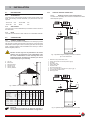
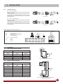
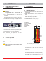
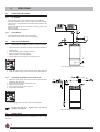
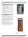
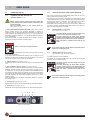
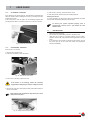
delta
performance
Combination boiler
25 / 35 / 45 / 55
delta
performance
F25 / F35 / F45 / F55
G25 / G35 / G45 / G55
Installation, Operating and
Servicing Instructions
excellence in hot water
11/06/2004 - 66400000
INDEX
1
1
INTRODUCTION
2
1.1
1.2
1.3
1.4
People who should read these instructions
Symbols
Applicable standards
Warnings
2
2
2
2
2
INSTALLATION
3
2.1
2.2
2.3
2.4
Boiler room
Connections
Oil supply
Electrical connections
3
3
5
6
3
STARTING UP
7
3.1
3.2
Filling the heating and domestic hot water circuits
Troubleshooting the burner
7
7
4
SERVICING
7
4.1
4.2
4.3
4.4
4.4
4.6
4.7
Recommendation
Servicing the gas boiler
Servicing the oil boiler
Servicing the safety devices
Servicing the burner
Emptying the boiler
Spare parts
7
7
7
7
8
8
8
5
DESCRIPTION
9
5.1
5.2
5.3
Overview
Description of operation
Build features
9
9
10
6
TECHNICAL SPECIFICATIONS
11
6.1
6.2
6.3
6.4
6.5
6.6
Effective dimensions
Maximum operating conditions
Domestic hot water performance
Boiler without burner
Boiler with ACV oil burner
Boiler with ACV BG 2000-S gas burner
11
11
11
11
12
13
7
USER GUIDE
14
7.1
7.2
Using the boiler
Boiler room
14
15
1.1
INTRODUCTION
PEOPLE WHO SHOULD READ THESE
INSTRUCTIONS
These instructions should be read by:
1.2
-
the specifying engineer
the installation engineer
the user
servicing technicians
SYMBOLS
The following symbols are used in these instructions:
Essential to ensure that the system works
properly.
Essential for personal safety and
environmental protection.
Danger of electrocution.
Danger of burns.
1.3
APPLICABLE STANDARDS
The products have been granted the “EC” certificate in accordance
with the standards in force in different countries (European Directives,
92/42/EEC “efficiency” and 90/396/ECC “gas devices”). These
products have also been granted the Belgian “HR+”(gas boilers) and
“OPTIMAZ” (oil boilers) marks.
1.4
WARNINGS
These instructions are an integral part of the equipment to which they
refer and the user must be provided with a copy.
The product must be installed and serviced by qualified engineers, in
compliance with current standards.
ACV cannot accept liability for any damage resulting from incorrect
installation or from the use of components or fittings not specified by ACV.
Any failure to follow instructions relating to tests and
test procedures may result in personal injury or risks of
pollution.
Because of their high level of performance our boilers
produce flue gas discharge at low temperatures. This
can cause condensation in some chimney flues. Your
installing engineer will advise you whether you need to
install a flue pipe in your chimney.
2
N.B.
ACV reserves the right to change the technical specifications and
components of its products without prior notice.
2
2.1
INSTALLATION
BOILER ROOM
2.2.2
2.2.2.1
Examples of basic circuit configurations
The drain cock and safety valve must be connected to the waste
water disposal system.
2.1.1
ACCESSIBILITY
The boiler room must be large enough to allow proper access to the
boiler. The following minimum distances (mm) around the boiler are
required:
- at the front
- at the rear
500
150
- at the sides
- above
CENTRAL HEATING CONNECTION
100
700
9
2.1.2
VENTILATION
The boiler room must be fitted with top and bottom vents as shown in
the table below.
2.2
3
CONNECTIONS
6
5
2.2.1
CHIMNEY CONNECTION
The boiler can be connected to a suitable flue or to chimney by a metal
pipe rising at an angle from the boiler to the chimney. It must be easily
removable in order to give access to the flue pipes when servicing the
boiler. A draught regulator must be installed on the chimney in order to
stabilise negative pressure.
10
Because of their high level of performance our boilers
produce flue gas discharge at low temperatures. This
can cause condensation in some chimney flues. Your
installing engineer will advise you whether you need to
install a flue pipe in your chimney.
Top vent
Bottom vent
Draught regulator
Inspection cover
Chimney height
Chimney diameter
Fig. 2: Hydraulic diagram showing circulator controlled
by a room thermostat.
1.
2.
3.
4.
5.
6.
7.
8.
9.
10.
F
E
A.
B.
C.
D.
E.
F.
7
4
2
2.1.3
BASE
The boiler must be laid on a base made of non-combustible materials.
9
Motorised 3-way manual mixer valve
Safety valve preset to 3 bar with pressure gauge
Circulator
Non-return valve
System filling valve
Expansion tank
Room thermostat (fig. 2)
ACV 13 controller (see controller kit on page 5) (fig. 3)
Central heating isolation valve
Discharge outlet
C
A
9
B
9
D
2
Fig. 1: Boiler room ventilation and chimney connection
Ventilation
25-F25
35-F35
45-F45
55-F55
G25
G35
G45
8
4
3
1
G55
6
Min. fresh air
requirement
m3/h
50/66
66/90
84/122
100/138
45
63
81
99
Top vent (A)
dm2
2
2
2
2
1,5
1,5
1,5
1,5
Bottom vent (B)
dm2
1,5
1,5
1,5
1,5/2,1
1,5
1,5
1,5
1,7
5
Chimney
E = 5m
Ø min.F
mm
158/182
182/213 208/248
226/266
160
189
215
236
E = 10m
Ø min.F
mm
133/153
153/179 175/209
190/223
135
159
181
199
E = 15m
Ø min.F
mm
130/138
138/162 158/188
172/202
130
143
163
179
Important
Boilers must be installed by an approved engineer, in
accordance with current local standards and regulations.
10
Fig. 3: Hydraulic diagram with motorised mixer valve
3
2
INSTALLATION
2.2.2.2
ACV hydraulic kit
ACV offers an optional pre-assembled hydraulic kit comprising:
- A circulator.
- A motorised 3-way manual valve.
- Connecting pipes including an optional second circuit.
- Two isolation valves.
- Connectors for mounting the safety valve with pressure gauge
and the filling valve to the right or left of the expansion tank.
2.2.2.3
Discharge
The drain cock and safety valve must be connected to the waste
water system in accordance with current regulations.
Fig. 4: Assembly with the ACV hydraulic kit
2.2.3
DOMESTIC HOT WATER CONNECTION
2.2.3.1
Pressure reducer
If the water mains pressure is greater than 6 bar, a pressure
reducer calibrated to 4.5 bar must be fitted.
5
2
7
4
8
1
2.2.3.2
Safety unit
The tank safety unit must be ACV approved and calibrated to 7
bar. The valve discharge must be connected to the waste water
system in accordance with current regulations.
9
6
2.2.3.3
Domestic hot water expansion tank
Installing a hot water expansion tank avoids any risk of pressure
surges due to waterhammer.
2.2.3.4
Hot water circulation
If the tank is located a long way from the point of use, then
installing a closed recirculation circuit ensures that a faster supply
of hot water is always available.
2.2.3.5
1.
2.
3.
4.
5.
6.
7.
8.
9.
Fig. 5a: Connection without thermostatic mixing valve
Description
Safety unit
Pressure reducer
Thermostatic mixing valve
Hot water circulator
Non-return valve
Domestic hot water type expansion tank
Inlet valve
Draw-off valve
Bleed valve
5
2
7
4
8
1
3
9
6
IMPORTANT
As a safety measure against burns, we strongly advise
installing a thermostatic mixing valve (recommended
temperature: 60° C).
This is available as an optional accessory
Safty unit
Pressure reducer
Thermostatic mixing valve
Expansion tank
4
Ø 3/4”
Ø 3/4”
Ø 3/4”
5 litres
Fig. 5b: Connection with thermostatic mixing valve
2
2.2.4
INSTALLATION
CONTROLLER KITS
KIT 1: ACV 13.00 / Basic
Basic kit for regulating initial flow temperature according to
weather conditions.
It comprises: a temperature regulator with analogue clock,
wall-mounted water temperature sensor (-30/130° C), external
sensor (-30/50° C), 3-pin servomotor SQY 31 230 V and an
intermediate base.
Fig. 5b: kit 1
KIT 1: ACV 13.00 / Standard
Basic kit for regulating initial flow temperature according to
weather conditions.
It comprises: a temperature regulator with analogue clock,
wall-mounted water temperature sensor (-30/130° C), external
sensor (-30/50° C), 3-pin servomotor SQY 349,230 V and an
intermediate base.
Fig. 5b: kit 2
Wiring diagram for ACV controller kits (fig. 7)
SQK 349
B2.
B9.
B5.
P1.
Wall-mounted temperature detector
External sensor
Analogue/digital room thermostat
Central heating pump
Y1/Y2/N.
Mixing valve (SQK349)
bl.
n/z.
br.
Blue N
Black Y2
Brown. Y1
230V
P1
B5
B9
B3
B2
QAAD50
(QAAD70) QAC32
QAD22
bl n/z br
20
19
18
17
16
15
14
13
N
12
11
10
9
8
7
6
5
4
3
2
L1
1
230V / 50 Hz
20
19
18
17
16
15
14
13
N Y2 Y1
2.3
OIL SUPPLY
2.3.1
INSTALLATION WITHOUT RETURN
12
11
10
9
P1
8
7
6
B5
5
4
B9
3
B3
1
2
B2
Ø int.
H (m)
8 mm
10 mm
0,5
10
20
1
20
40
1,5
40
80
2
H
L1
Fig. 8a: Oil supply without return
100
INSTALLATION WITH RETURN
L1
L (m)
H
Ø int.
Ø int.
H (m)
8 mm
10 mm
0
35
100
0,5
30
100
1
25
100
1,5
20
90
2
15
70
2
8
30
3,5
6
20
max 4m
2.3.2
60
max 4m
L (m)
Ø int.
H
L1
Fig. 8b: Oil supply with return from either top
or bottom mounted tank
5
2
2.4
INSTALLATION
ELECTRICAL CONNECTION
It is important to switch the boiler off before carrying out
any work.
2.4.1
DESCRIPTION OF POWER SUPPLY
The boiler operates on single phase 230 V – 50 Hz. An on-off switch
box with 6 A fuses must be fitted outside the boiler to allow power to
be shut off during servicing and before any repairs are carried out on
the boiler.
1
3
2 4
5
2.4.2
COMPLIANCE
Boiler installation must comply with current local standards and
legislation.
2.4.3
SAFETY
The stainless steel tank must be earthed separately.
2.4.4
BURNER ELECTRICAL CONNECTION
The burner is powered through a 3-core cable, which is plugged into
the connector in the lower right hand corner of the burner chamber
plate. Details of how to connect it up aregiven in the technical
instructions for the burner.
10
N T1 T2 S3 B4
L1
M
1
1
2
C
T
M
O
3
B
6
N
O
Fig. 9 Control panel
1.
2.
3.
4.
5.
6.
7.
8.
9.
10.
11.
PH:
N:
M:
VM 1:
VM 2:
PF:
T:
AL:
CF:
M.
O.
N.
B.
T.
G.
J.
Boiler thermostat (60/90° C)
On/off switch
Summer/Winter selector switch
Thermometer
Controller (optional)
Safety thermostat (95° C max.)
Safety thermostat (103° C max.)
Plug for power and control
Central heating circulator connection
Burner connection
Room thermostat
Phase
Neutral
Motor
Magnetic valve 1
Magnetic valve 2
Oil preheating
Ignition transformer
Alarm
Photoelectric cell
CF
M VM2
VM1 PF
B
7
T
AL
PH N
O
1 2 3 4 5 6 7 8 9 10 11 12
N
B
2
10
M
L1
B
L1
N T1 T2 S3 B4
Fig. 10 b: Oil burner
N T1 T2 S3
1 2 3 4 5 6 7 8 9 10 11 12
L1 N
L1
N T1 T2 S3
M
BV
B
N
JGM
G
M
230V-50 Hz
6A
8
11
9
Fig. 10 a: Boiler wiring
6
10
L1
N
B
M V
J
N T1 T2 S3 B4
Fig. 10 c: Gas burner
Brown
Orange
Black
Blue
Green-yellow
Grey
Yellow
3
3.1
STARTING UP
FILLING THE HEATING AND DOMESTIC
HOT WATER CIRCUITS
1. Fill the domestic hot water circuit and bring it up to pressure.
4
4.1
RECOMMENDATION
ACV recommend that boilers should be serviced at least once a year.
The burner must be serviced and tested by a competent engineer.
4.2
2. Fill the heating circuit taking care not to exceed the 2 bar
pressure limit.
3. Bleed the air from the top of the boiler.
4. After bleeding the air out of the system, bring the pressure up to the
static pressure (height) plus 0.5 bar: 1.5 bar = 10 m – 2 bar = 15 m.
5. Check the power connection, the boiler room ventilation and ensure
that there are no leaks in the flue gas discharge pipes.
6. Set the thermostat (1) to between 60 and 90° C.
3
SERVICING THE BOILER
1 - Switch the power off at the mains switch outside the boiler and
close the gas tap.
2 - Set the on/off switch on the control panel to the OFF position.
3 - Release and remove the chimney flue (1) to free the top of the
boiler.
4 - Remove the jacket top (2) and lift off the flue reducer (3).
5 - Remove the baffles (4) from the flue pipes (5) for cleaning.
Replace them if they are in poor condition.
6 - Remove the chamber plate (6).
7 - Brush the flue pipes (5).
8 - Clean the burner chamber (7) and the burner (8).
9 - Check the insulation on the chamber plate (6)
IMPORTANT
The hot water tank must be pressurised before the
heating circuit is filled.
1
SERVICING
2
1.
2.
3.
4.
5.
6.
7.
8.
Chimney flue
Jacket cover
Chimney flue reducer
Baffles
Flue pipes
Chamber plate
Combustion chamber
Burner
1
2
3
Fig. 11: Control panel
7.
8.
9.
10.
Set the Summer/Winter selector switch (3) to the desired position.
Switch the on/off switch (2) to the ON position.
Check the pressure of the gas supply when starting up.
For the oil burner check the oil supply (and return).
Carry out any bleeding, measuring and adjustment work which
may be necessary.
5
3.2
4
TROUBLESHOOTING THE BURNER
3.2.1
ACV BG 2000-S GAS BURNER
Please refer to the servicing and troubleshooting instructions for the
burner.
6
8
7
3.2.2
ACV OIL BURNER
Please refer to the servicing and troubleshooting instructions for the
burner.
Before carrying out any servicing or repair work, switch
the power off at the mains switch fitted in the boiler room
by the electrician.
Fig. 12: Description of the main components
which require servicing.
4.3
-
4.4
-
-
SERVICING THE OIL BOILER
Switch the power off at the mains switch outside the boiler and
close the oil inlet.
Proceed following instructions 2 to 9 in paragraph (4.2 Servicing
the gas boiler).
SERVICING THE SAFETY DEVICES
Check that all thermostats and safety devices are working properly:
boiler thermostat, cut-off thermostat and manually reset safety
thermostat.
Check the safety valves on both the central heating and the hot
water circuits.
7
4
SERVICING
4.5
SERVICING THE BURNER
4.5.1
OIL BURNER
-
Check the main filter on the oil line and clean it if necessary.
Check the nozzle line: check, clean or change the nozzle and filter,
check that it is clean and that the electrodes and flame holder are
properly set.
Replace the whole unit and check that the safety devices are
working properly
Adjust the combustion parameters.
-
4.5.2
-
1
1
GAS BURNER
Check and clean the burner and the electrodes.
Check that the safety devices are working properly.
4.6
EMPTYING THE BOILER
4.6.1
EMPTYING THE PRIMARY CIRCUIT (CENTRAL HEATING):
1. Switch the power to the boiler off at the mains switch installed by
the electrician.
2. Close the boiler system’s isolating valves (1).
3. Connect a hose to the drain cock (2).
Make sure that it is properly attached.
4. Open the drain cock and let the hot water drain out.
2
Fig. 13a: Emptying the primary circuit
5. When the boiler is empty, return the valves to their initial positions
4.6.2
EMPTYING THE DOMESTIC HOT WATER TANK:
1. Switch the mains power to the boiler off at the external switch
installed by the electrician.
2. Remove the pressure from the primary circuit.
3. Close valves (A) and (B).
4. Open valves (C) and (D) (first C then D).
5. Let the water drain away.
6. After emptying, return the valves to their initial positions.
To allow the tank to be emptied, valve (C) must be
situated at ground level.
4.7
SPARE PARTS
Please refer to the specific document available from ACV or your
distributor.
8
B
A
D
C
Fig. 13b: Emptying the hot water circuit
5
5.1
•
•
•
•
•
•
•
•
•
DESCRIPTION
OVERVIEW
Combination boiler (central heating and domestic hot water).
Designed for connection to a chimney.
TANK-IN-TANK indirect storage type domestic hot water production.
Fittings required to connect the hydraulic kit for feeding the heating
circuit (available as an optional extra).
Control panel with on/off switch, adjustable thermostat,
thermometer, Summer/Winter selector and knockout for fitting ACV
integrated control system (optional).
DELTA Performance 25, 35, 45 and 55 models - with effective
outputs adjustable between 22 and 62 kW - are shipped without
burners. They can be fitted with most gas or oil burners available
on the market.
DELTA Performance F25, F35 and F45 models - with effective
outputs adjustable between 22 and 54 kW - are shipped with an
ACV BM R oil burner.
DELTA Performance F55 models - with effective outputs adjustable
between 45 and 62 kW - are shipped with an ACV BM oil burner.
DELTA Performance G25, G35, G45 and G55 models - with
effective outputs adjustable between 22.5 and 49 kW - are shipped
with a BG 2000-S gas burner.
5.2
DESCRIPTION OF OPERATION
5.2.1
THE TANK-IN-TANK CONCEPT
Fig. 14: Stainless steel domestic hot water tank
The DELTA Performance series differs from traditional hot water
producers in that it has a ring-shaped tank immersed in the primary
fluid contained in the outer body. When hot water from the central
heating system or the domestic hot water system is needed, the
thermostat starts up the burner. The combustion gases quickly heat up
the primary fluid, thus creating a natural circulation around the tank.
4
5.2.2
INDIRECTLY HEATING DOMESTIC HOT WATER
This circulation allows easier heat exchange between the primary fluid
and the domestic water, all over the tank surface. The corrugations on
the inner and outer shells of the ring-shaped tank increase the area of
heat exchange still further and thus speed up the process of heating
the domestic water.
5.2.3
EASY TO SET AND SAFETY ASSURED
With a single command, the water temperature of both the primary
circuit and the domestic hot water circuit can be set by the adjustable
thermostat situated underneath the tank in the primary circuit.
A cut-off thermostat, placed on the top of the boiler automatically
switches off the burner when the temperature of the water in the
primary circuit reaches 95° C. A manually reset safety thermostat
switches off the burner if the temperature reaches 103° C.
2
4
1
3
5
Fig. 15: Brief description of the boiler
1. Primary fluid
2. Domestic hot water
3. Combustion chamber
4. Control thermostat
5. Burner
9
5
5.3
DESCRIPTION
BUILD FEATURES
5.3.1
OUTER BODY
The outer body containing the primary fluid is made of STW 22 steel.
5.3.2
TANK-IN-TANK TYPE EXCHANGER ACCUMULATOR
The ring-shaped inner tank with its large heating surface, used for
producing domestic hot water, is built using Chrome/Nickel 18/10
stainless steel. It is corrugated all the way up to the top using an
exclusive production process and entirely argon arc welded using the
TIG (Tungsten Inert Gas) method.
5.3.3
COMBUSTION GAS CIRCUIT
The combustion gas circuit is protected by a coat of paint. The
combustion gas circuit comprises:
5.3.3.1
Flue pipes
Depending on output, the various DELTA Performance models
contain either 4 or 8 steel flue pipes with an inner diameter of 64
mm. Each pipe is fitted with a special steel baffle designed to
improve heat exchange and reduce the flue gas temperature.
1.
2.
3.
4.
5.
6.
7.
8.
9.
10.
11.
12.
13.
14.
15.
16.
17.
18.
19.
Inner ring-shaped tank containing the domestic hot water
External body containing central heating circuit
Insulation
Jacket
Flue pipes
Baffles
Thermostat adjustable between 60° and 90° C
Lower central heating return
Combustion chamber
Chamber plate
Emptying the boiler
Upper central heating flow pipe and return
Chimney connection
Control panel
Domestic hot water outlet
Domestic cold water inlet
Cut-off thermostat 95° C / Thermometer
Manually reset 103° C safety thermostat
Gas or oil burner
5.3.3.2
Combustion chamber
All DELTA Performance models feature a fully water-cooled
combustion chamber.
5.3.4
INSULATION
The boiler body is fully insulated by rigid polyurethane foam with a high
thermal insulation coefficient. This is sprayed onto the tank without
using any CFCs.
5.3.5
JACKET
The boiler is covered by a steel jacket which has been scoured and
phosphated before being stove finished at 220° C.
13
17
4
15
7
14
12
16
18
5.3.6
BURNER
DELTA Performance F25 and F35 boilers are shipped with the ACV BM
R 31 gas burner, F45 boilers are fitted with the ACV BM R 51
burner and the F55 boiler can be fitted with the ACV BM 101 burner.
These new generation burners incorporate the latest technological
developments and meet all safety, efficiency and clean combustion
requirements. They come fitted with a preheating device, with the
exception of the BM 101. DELTA G25, G35, G45 and G55 performance
boilers all ship with the ACV BG 2000-S gas burner.
1
2
3
5
6
IMPORTANT
For assembly, the various settings, start-up and servicing
please see the technical instructions which come with
the burner.
7
10
8
9
19
11
5.3.7
1
2
3
4
5
-
CONTROL PANEL (FIG. 17)
Thermostat adjustable between 60° and 90° C
On/off switch
Summer/Winter selector switch
Thermometer
Knockout for control system (optional).
Fig. 16: The boiler
1
3
2 4
Fig. 17: Control panel
10
5
6
6.1
TECHNICAL SPECIFICATIONS
EFFECTIVE DIMENSIONS
Units are shipped fully assembled, tested and packed on a timber base
with shockproof edges and protected by a heat-shrunk plastic film.
On reception and after unpacking, check the equipment for any damage.
For transportation purposes, please see the weights and dimensions
given below:
200
MAXIMUM OPERATING CONDITIONS
160
6.2
B
570
A
Maximum operating pressure (tank full of water)
- Primary circuit: 3 bar
- Secondary circuit: 10 bar
C
118 158
Test pressure (tank full of water)
- Primary circuit: 4.5 bar
- Secondary circuit: 13 bar
Operating temperature
- Maximum temperature: 90° C
542
D
Fig. 18: Effective dimensions
Dimensions
25
35
45
55
F25
F35
F45
F55
G25
G35
G45
G55
A
1497
1697
1497
1697
1497
1697
1497
1697
1497
1697
1497
1697
B
130
130
150
150
130
130
150
150
130
130
150
150
C
360
360
390
390
360
360
390
390
360
360
390
390
D
565
565
565
565
818
818
818
848
755
755
755
755
Kg
145
156
168
200
157
168
180
212
159
170
182
214
6.3
DOMESTIC HOT WATER PERFORMANCE
Domestic hot water performance
25 - F25 - G25
35 - F35 - G35
45 - F45 - G45
55 - F55 - G55
OPERATING AT 80° C
Peak flow at 40° C
(∆ T = 30° C)
l/10’
268
285
316
362
Peak flow at 40° C
(∆ T = 30° C)
l/60’
806
1035
1284
1533
Continuous flow 40° C
(∆ T = 30° C)
l/h
645
900
1161
1405
Start-up
minutes
32
29
16
16
After drawing off 140 l at 45° C
minutes
15
11
9
7
25
35
45
55
50/69
OPERATING AT 80° C
6.4
BOILERS WITHOUT BURNER
Heat release rate (input)
kW
25/33
33/45
42/61
Effective rated output (output)
kW
22/29
29/40
38/54
45/62
%
1,36/1
1/0,79
0,8/0,56
0,75/0,6
Maintenance loss at 60°C as % of rated value
Total capacity
l
157
178
132
162
Primary circuit capacity
l
83
104
70
82
Central heating connection
Ø
1”
1”
1”
1”
Domestic hot water connection
Ø
3/4”
3/4”
3/4”
3/4”
Hot water tank heat exchange surface
m2
1,59
1,59
1,99
2,46
Weight when empty
Kg
145
156
168
200
11
6
TECHNICAL SPECIFICATIONS
Chamber plate (oil)
The chamber plate has 4 screws
(M 10 x 20) for the fixing of the
burner. It is protected from the
radiation of the flame by an
insulation blanket.
18
4 x Ø6.5 (M8)
Ø28
Ø112
53
53
275
53
53
Fig. 19: Combustion chamber door detail
6.5
BOILERS WITH ACV OIL BURNER
6.5.1
GENERAL SPECIFICATIONS
F25
F35
F45
F55
Heat release rate (input)
kW
25/33
33/45
42/61
50/69
Effective rated output (output)
kW
22/29
29/40
38/54
45/62
Combustion efficiency
%
91,7
90,5
91
92,5
Maintenance loss at 60°C as % of rated value
%
1,36/1
1/0,79
0,8/0,56
0,6/0,45
g/sec.
11
14,3
18,1
28,9
%
13
13
13,3
13
Total capacity
litres
157
178
132
151
Primary circuit capacity
82
Mass flow rate of combustion products
Average CO2
litres
83
104
70
Central heating connection
Ø
1”
1”
1”
1”
Domestic hot water connection
Ø
3/4”
3/4”
3/4”
3/4”
Hot water tank heat excange surface
m2
1,59
1,59
1,99
2,46
Weight when empty
Kg
157
168
180
214
F25
F35
F45
F55
BM R 31
BM R 31
BM R 51
BM 101
12/48
12/48
42/60
55/130
W
150
150
150
185
gal/h
0,6
0,75
0,85
1,50
60°
60°
60° B
60° B
Kg/h
2,18
2,84
3,60
5,76
bar
11,2
12
15
10
Flue gas index
0,6
0,3
0,4
0,5
Air flap setting
4,5
4,8
4,5
5
1
2,83
4 at 5
0,02/0,09
0,08/0,09
0,01/0,08
0,02/0,05
12
12
12
14
6.5.2
OIL BURNER SPECIFICATIONS
BRULEUR
Output
Electrical power
Nozzle
kW
Nozzle angle
Oil flow rate
Pump pressure
Combustion head setting
Flue pressure drop
Weight
mbar
Kg
Fig. 20: ACV oil burner specifications
12
A
B
C
D
E
F
G
L
LK
mm
mm
mm
mm
mm
Ø
Ø
Ø
BM R 31
BM R 51
BM 101
240
270
215
280
60 - 130
M8
80
85
140 - 165
240
270
215
280
60 - 130
M8
80
85
140 - 165
260
300
250
310
60 - 150
M8
90
95
125 - 180
6
TECHNICAL SPECIFICATIONS
6.6
BOILERS WITH ACV BG 2000-S GAS BURNER
6.6.1
BURNER SPECIFICATIONS / REFERENCE GAS
Burners
G25
G35
G45
G55
BG 2000-S/25
BG 2000-S/35
BG 2000-S/45
BG 2000-S/55
Heat release rate (input)
kW
25
34,9
45
55
Effective rated output (output)
kW
22,45
31,35
40,5
49
Combustion efficiency
%
91,7
91,5
92,4
92
CO2 natural gas
%
9,1
9
8,9
9
Flow
Upstream gas pressure
m /h
2,65
3,70
4,76
5,8
mbar
20
20
20
20
3,07
4,3
5,52
7,98
25
25
25
25
m3/h
Upstream gas pressure
mbar
FR
I 2Er
AT - DK
I 2H
IT - PT
IE - SE
Gas G25 - 20 mbar - I 2ELL / 25 mbar - I 2L
Flow
I 2E(S)B
ES - GB
Gas G20 - 20 mbar - I 2E(S)B - I 2Er - I 2H - I 2ELL - I 2E
3
BE
BE - FR
ES - GB
I 3P
IE - PT
Gas G31 - 30/37/50 mbar - I 3P
Flow
Upstream gas pressure
m3/h
1,02
1,43
1,84
2,25
mbar
37/50
37/50
37/50
37/50
Net T° of burnt gases
°C
170
173
153
165
Flow
%
1,36
1
0,8
0,7
Kg
159
170
182
214
B23
B23
B23
B23
Upstream gas pressure
Type of chimney connection
6.6.2
ACV BG 2000-S AIR/GAS PREMIX GAS BURNERS
The air/gas premix BG 2000-S burner is fitted with a Honeywell gas
valve, a venturi tube and an electrical control relay. The gas valve has
been specially developed for low NOx air/gas premix burners with
automatic lighting and flame detection by ionisation.
The pressure at the gas valve outlet is equal to the air pressure at the
neck of the venturi tube, reduced as the offset is adjusted. The fan
sucks in the combustion air through the venturi tube which the gas inlet
leads into. As it goes through, the air creates a vacuum to the right of
the neck of the venturi tube and sucks in the gas at the venturi tube
outlet. A perfect air/gas mix then goes through the fan and then goes
on towards the ramp.
Venturi
NL
I 2L
DE
I 2ELL
LU
I 2E
Fan
Air/gas
mix
Air
Offset adjustement
screw
Gas
Gas flow
adjustement screw
Fig. 21: Wiring diagram
The electrical control relay built into the gas valve ensures that the
flame on the burner is properly it and controlled.
This principle guarantees silent and totally safe operation:
N
O
P
Q R
• if there is not enough air, the vacuum in the venturi tube falls, the gas
flow is reduced, the flame goes out and the gas valve is closed. The
burner is locked out.
• if there is any restriction in the discharging of the burnt gases, the air
flow drops and this leads to the same reactions as those described
above leading to the burner being shut down, locked out.
S
N.
O.
P.
Q.
R.
S.
T.
Burner ramp
Ignition electrodes
Chamber plate insulation
Gas valve
Reset
Ionisation electrode
Venturi tube
T
Fig. 22a: Side view of the 2000-S
The BG 2000-S burner is factory preset to
natural gas.
U.
V.
W.
X.
Conversion to propane:
Relay
Gas inlet
Fan
Burner connector
Prohibited in Belgium.
Conversion kit enclosed with the burner
comprising:
- Gate disk(s)
- Rating plate(s).
- Settings sticker.
- Assembly instructions.
U
V
W
X
Fig. 22b: Frontal view of the BG 2000-S
13
7
USER GUIDE
7.1
USING THE BOILER
7.1.2
7.1.1
LEARNING YOUR WAY AROUND THE
CONTROL PANEL (FIG. 23)
Your system is fitted with a central heating safety valve, set to 3 bar,
which is fitted with a pressure gauge.
First make sure that the water in the system is still pressurised. When
cold and after the air in the system has been bled, the pressure gauge
should show a pressure of between 1 and 2, depending on the height
of the building: (1 bar = 5m / 1.5 bar = 10 m and 2 bar = 15 m).
To add water, open the filling valve (Fig. 2 and 3 on page 3). Make sure
the valve is properly closed after filling. Bleed the air in the system to
get an accurate water pressure reading.
Before carrying out any work on the boiler, switch the
power off at the mains switch installed in the boiler room
by the electrician.
Turn the ON/OFF switch on the control panel off.
(item marked 2, Fig. 23)
1 - Thermostat adjustable between 60 and 90° C (item marked 1, Fig. 23)
Central heating systems are generally designed to operate at
amaximum of 80° C. When used at lower temperatures, a 3-way mixer
valve installed on the heating flow pipe (see Fig. 3 on page 3) allows the
temperature to be set manually or, if you decide to install a regulator (§
2.2.4), automatically.
We recommend that you set the thermostat to the maximum values to
get the best out of the domestic hot water system.
7.1.3
2 - ON/OFF switch (item marked 2, Fig. 23)
This must be used to switch the boiler off before carrying out any work
on it.
3 - Summer/Winter selector switch (item marked 3, Fig. 23)
“Winter” position: provides both domestic hot water and central heating
functions. “Summer” position: The room thermostat or regulator (§ 2.2.4)
is switched off. The central heating circulator is also switched off. Only
the domestic hot water function is provided. You can use the thermostat
(1) to reduce the temperature and save energy. If there is not enough
hot water available, we recommend setting the thermostat (1) to its
maximum value.
When the weather turns cold again, simply select “Winter” to reactivate
the heating system.
4 - Thermometer (item marked 4, Fig. 23)
Reads the boiler primary circuit (central heating) temperature directly.
5 - Controller (item marked 5, Fig. 23)
Please refer to the enclosed instructions if you have chosen this option.
1
3
2 4
Fig. 23: Control panel
14
5
SAFETY VALVE (central heating)
(item marked 2, Fig. 3 on page 3)
The water, which may flow out of the safety valve
is very hot and may cause serious burns.
The pipe discharging to waste water disposal
systeme should be open to the atmosphere and
installed in accordance with current regulations.
Make sure there is nobody near the flow of hot
water.
There is a risk of burns from hot water!
The water stored in the domestic hot water tank in the boiler can be at
a very high temperature.
In all cases, install the thermostatic mixer (Fig. 5b on page 4) on the
domestic hot water flow pipe which must not exceed 60° C. A mixer or
mixing valve at each point of use is recommended.
CENTRAL HEATING SYSTEM GAUGE PRESSURE
If you notice anything unusual after this short trial, please
inform the installing engineer.
7.1.4
SAFETY UNIT (domestic hot water)
(item marked 1, Fig. 5a and 5b on page 4)
A monthly inspection is recommended:
Lift the lever on the emptying device for a few seconds to ensure that
the safety valve is working properly.
The water flowing out of the safety unit may be
extremely hot.
The pipe discharging to waste water disposal
systeme should be open to the atmosphere and
installed in accordance with current regulations.
Make sure there is nobody near the flow of hot
water.
If you notice anything unusual after this short trial, please
inform the installing engineer.
7
7.1.5
USER GUIDE
OIL BURNER - RESETING
If the red light on the burner lights up, this indicates an operating fault.
Wait five minutes before resetting the burner by pressing the button
located on the cover.
If the burner fails to start up again, call the installing engineer after
ensuring that the fault is not due to a power cut or low oil in the tank.
5. If the burner is working, replace the burner cover.
6. If the fault persists, please notify the installing engineer.
Starting the burners.
In normal operation, the gas burner starts up automatically provided
that the boiler temperature falls below the set point.
To ensure your system operates properly, have it
professionally serviced once a year before the cold
weather starts.
7.1
•
•
•
•
Fig. 24: Oil burner reset button
7.1.6
BOILER ROOM
Keep vents free at all times.
Do not store any inflammable products in the boiler room.
Take care not to store any corrosive products, such as paints,
solvents, chlorine, salt, soap and other cleaning products, near the
boiler.
If you smell gas, do not switch on the light or light a flame. Turn off
the mains gas tap at the meter and inform the appropriate
services immediately.
GAS BURNER - RESETING
If the burner is not working:
1. Remove the protective cover.
2. Press the “red” button to start the burner.
Fig. 25: Gas burner reset button
3. If the burner is working, replace the cover.
If the burner is not working, isolate the electricity
supply before attempting to reset the safety thermostat.
4. Remove the front panel and reset the safety thermostat located on
the top of the boiler.
Wait until the boiler temperature drops below 60°C. Then
replace the front panel.
Fig. 26: Safety thermostat reset button.
15
www.acv-world.com
excellence in hot water
INTERNATIONAL
FRANCE
SLOVAK REPUBLIC
ACV international n.v
KERKPLEIN, 39
B-1601 RUISBROEK - BELGIUM
TEL.: +32 2 334 82 20
FAX: +32 2 378 16 49
E-MAIL: [email protected]
ACV FRANCE sa
31, RUE AMPERE - Z.I MI - PLAINE
F-69680 CHASSIEU - FRANCE
TEL.:+33 4 72 47 07 76
FAX:+33 4 72 47 08 72
E-MAIL: [email protected]
ACV SLOVAKIA s.r.o.
PLUHOVÁ 49
831 04 BRATISLAVA - SLOVAK REPUBLIC
TEL.:+421 2 444 62 276
FAX:+421 2 444 62 275
E-MAIL: [email protected]
BELGIUM
ITALIA
SLOVENIA
ACV BELGIUM nv/sa
KERKPLEIN, 39
B-1601 RUISBROEK-BELGIUM
TEL.: +32 2 334 82 40
FAX: +32 2 334 82 59
E-MAIL: [email protected]
ACV ITALIA
VIA PANA 92
I-48018 FAENZA (RA) - ITALIA
TEL.:+39 0546 64 61 44
FAX:+39 0546 64 61 50
E-MAIL: [email protected]
ACV D.O.O. SLOVENIA
OPEKARNA 22b
1420 TRBOVLJE - SLOVENIA
TEL.:+386 356 32 830
FAX:+ 386 356 32 831
E-MAIL: [email protected]
CHILE
NEDERLAND
UK
ALBIN TROTTER Y ACV LTDA
SAN PABLO 3800
QUINTA NORMAL - SANTIAGO - CHILE
TEL.:+56 2 772 01 69
FAX:+56 2 772 92 62/63
E-MAIL: [email protected]
ACV NEDERLAND bv
POSTBUS 350
NL-2980 AJ RIDDERKERK - NEDERLAND
TEL.:+31 180 42 10 55
FAX:+31 180 41 58 02
E-MAIL: [email protected]
ACV UK Ltd
ST. DAVID’S BUSINESS PARK
DALGETY BAY - FIFE - KY11 9PF
TEL.:+44 1383 82 01 00
FAX:+44 1383 82 01 80
E-MAIL: [email protected]
CZECH REPUBLIC
POLAND
USA
ACV CR SPOL. s.r.o
NA KRECKU 365
CR-109 04 PRAHA 10 - CZECH REPUBLIC
TEL.:+420 2 720 83 341
FAX:+420 2 720 83 343
E-MAIL: [email protected]
ACV POLSKA sp. z.o.o.
UL.WITOSA 3
87 - 800 WLOCLAWEK - POLAND
TEL.:+48 54 412 56 00
FAX:+48 54 412 56 01
E-MAIL: [email protected]
TRIANGLE TUBE PHASE III
FREEWAY CENTER - 1 TRIANGLE LANE
BLACKWOOD NJ 08012 - USA
TEL.:+1 856 228 8881
FAX:+1 856 228 3584
E-MAIL: [email protected]
DEUTSCHLAND
PORTUGAL
ACV WÄRMETECHNIK GMBH & CO KG
GEWERBEGEBIET GARTENSTRASSE
D-08132 MÜLSEN OT ST. JACOB - DEUTSCHLAND
TEL.:+49 37601 311 30
FAX:+49 37601 311 31
E-MAIL: [email protected]
BOILERNOX LDA
RUA OUTEIRO DO POMAR
CASAL DO CEGO, FRACÇÃO C,
PAVILHÃO 3 - MARRAZES
2400-402 LEIRIA - PORTUGAL
TEL.:+351 244 837 239/40
FAX:+351 244 823 758
E-MAIL: [email protected]
ESPAÑA
ACV ESPAÑA
C/DE LA TEIXIDORA, 76
POL. IND. LES HORTES
E-08302 MATARÓ - ESPANA
TEL.:+34 93 759 54 51
FAX:+34 93 759 34 98
E-MAIL: [email protected]
RUSSIA
ACV RUSSIA
1/9, MALYI KISELNYI
103031 MOSCOW - RUSSIA
TEL.:+7 095 928 48 02 / +7 095 921 89 79
FAX:+7 095 928 08 77
E-MAIL: [email protected]
ARGENTINA
DENMARK
NEW ZEALAND
TECNOPRACTICA
ALFEREZ BOUCHARD 4857
1605 CARAPACHAY - BUENOS AIRES
TEL.: +54 11 47 65 33 35
FAX: +54 11 47 65 43 07
E-MAIL: [email protected]
VARMEHUSET
FRICHSVEJ 40 A
8600 SILKEBORG - DENMARK
TEL.:+45 86 82 63 55
FAX:+45 86 82 65 03
E-MAIL: [email protected]
ENERGY PRODUCTS INTERNATIONAL
8/10 BELFAST PLACE
PO BOX 15058 HAMILTON - NEW ZEALAND
TEL.:+64 7 847 27 05
FAX:+64 7 847 42 22
E-MAIL: [email protected]
AUSTRALIA
ESTONIA
ÖSTERREICH
TERMOX AS
TAHE 112A
51013 TARTU - ESTONIA
TEL.:+372 736 73 39
FAX:+372 736 73 44
E-MAIL: [email protected]
PROTHERM HEIZUNGSTECHNIK Gmbh
TRAUNUFERSTRASSE 113
4052 ANSFELDEN - ÖSTERREICH
TEL.:+43 7229 804 82
FAX:+43 7229 804 92
E-MAIL: [email protected]
GREECE
ROMANIA
ESTIAS
MARASLI STREET 7
54248 THESSALONIKI - GREECE
TEL.:+30 23 10 31 98 77 / +30 23 10 32 03 58
FAX:+30 23 10 31 97 22
E-MAIL: [email protected]
SC TRUST EURO THERM SA
D.N PIATRA NEAMT - ROMAN
km 2 C.P 5 O.P 3 jud. Neamt
5600 PIATRA NEAMT - ROMANIA
TEL.:+40 233 20 62 06
FAX:+40 233 20 62 00
E-MAIL: [email protected]
HUNT HEATING PTY LTD
10 GARDEN BOULEVARD
3172 VICTORIA - AUSTRALIA
TEL.: +61 3 9558 7077
FAX: +61 3 9558 7027
E-MAIL: [email protected]
BRAZIL
SIMETAL INDUSTRIA E COMERCIO
DE FERRAMENTAS LTDA
RUA GERSON ANDREIS 535
95112 - 130 CAXIAS DO SUL - BRAZIL
TEL.: +55 54 227 12 44
FAX: +55 54 227 12 26
E-MAIL: [email protected]
BULGARIA
PROXIMUS ENGINEERING LTD
7 BIAL KREM STR.
9010 VARNA - BULGARIA
TEL.:+359 52 500 070
FAX:+359 52 301 131
E-MAIL: [email protected]
CHINA
BEIJING HUADIAN HT POWER TECHNOLOGY
DEVELOPMENT CO. LTD
ROOM B-912, TOWER B, COFCO PLAZA
N°. 8, JIANGUOMENNEI AVENUE
BEIJING 100005 - PEOPLE’S REPUBLIC OF CHINA
TEL.:+86 10 652 30 363/393 EXT 101
FAX:+86 10 652 27 071
E-MAIL: [email protected]
SHANGHAI COOLTECH LTD
14/F E. CHINA MERCHANTS PLAZA
N°. 333 CHENGDU ROAD (N)
200041 SHANGHAI - CHINA
TEL.:+86 21 52 98 11 22 - 820
FAX:+86 21 52 98 13 58
E-MAIL: [email protected]
ÎLE MAURICE
SOTRATECH
29, RUE MELDRUM
BEAU BASSIN - ÎLE MAURICE
TEL.:+230 46 76 970
FAX:+230 46 76 971
E-MAIL: [email protected]
TUNISIE
LITHUANIA
UKRAINE
UAB “GILIUS IR KO”
SAVARNORIU PR. 192
3000 KAUNAS - LITHUANIA
TEL.:+370 37 308 930
FAX:+370 37 308 932
UKRTEPLOSERVICE LTD
PR. LAGUTENKO 14
83086 DONETSK - UKRAINE
TEL.:+38 062 382 60 47/48
FAX:+38 062 335 16 89
MAROC
CASATHERM
PLACE EL YASSIR
20300 CASABLANCA - MAROC
TEL.:+212 22 40 15 23
FAX:+212 22 24 04 86
SO.CO.ME CHAUMAX
BOÎTE POSTALE N°44
1002 TUNIS - TUNISIE
TEL.:+216 71 78 15 91
FAX:+216 71 78 87 31