1
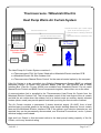
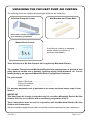
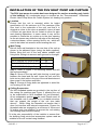
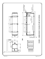
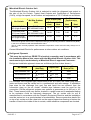
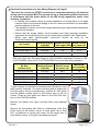
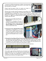
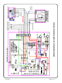
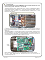
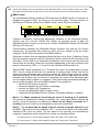
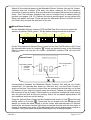
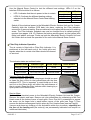
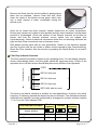
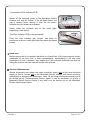
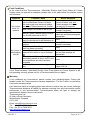
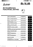
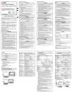
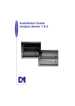
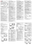
PHV HEAT PUMP RANGE AIR CURTAINS
INSTALLATION, OPERATION & MAINTENANCE INSTRUCTIONS
PLEASE READ THESE INSTRUCTIONS CAREFULLY BEFORE ATTEMPTING INSTALLATION
Thermoscreens Ltd
St. Mary’s Road Nuneaton
Warwickshire England
CV11 5AU
Email: [email protected]
Tel: +44 (0) 24 7638 4646
Fax: +44 (0) 24 7638 8578
www.thermoscreens.com
9901025-1
UK
Page 1 of 17
Thermoscreens / Mitsubishi Electric
Heat Pump Warm Air Curtain System
Communications Link
Manual On/Off Control and
Permanent 400V / 3ph / 50Hz supply
(from local switched spur) for
x Defrost Electric Heating Elements
x Fans
x Mitsubishi Electric Interface PCB
Heat Setting Control
Heat Pump
Air Curtain
Optional
BMS Control
Interface Board
Mitsubishi Electric
Outdoor Unit
Manual Room
Control
Procon
A32/M
The Heat Pump Air Curtain System consists of :• a Thermoscreens 'PHV Air Curtain' fitted with a Mitsubishi Electric Interface PCB
• a Mitsubishi Electric 'Mr Slim Outdoor Unit'
• a Thermoscreens 'Manual Room Control' for the manual control option by the occupant
If the Air Curtain is to be controlled via a Building Management System (BMS) an optional
Mitsubishi Electric 'A-Control Sub Interface Board' (Part No. PAC-SK82SI) and a 'BMS
Interface Box' (Part No. Procon A32/M) are available from Mitsubishi Electric. Do not install
Manual Room Control and BMS Control components together, have either one or the other.
A communications link is supplied to the Thermoscreens Heat Pump Air Curtain from the
Mitsubishi Electric Outdoor Unit. This link provides control of the heat output of the air curtain
and tells the air curtain when the outdoor unit is in defrost mode so auxiliary electric element
heaters (where used) can provide partial heat back-up during the few minutes of defrost.
The Air Curtain requires a permanent 3 phase electrical supply (3L+N+E) from a local
switched spur to provide power to the defrost cycle electric heating elements, the air curtain
fans and the Mitsubishi Electric Interface PCB. If the defrost cycle electric elements are not
required they can be permanently disconnected, see 'Electrical Connections', and a 1 phase
electrical supply used instead.
High and Low Output in this document refers to the heat pump heating capacity of the Air
Curtain, not to any electrical rating.
9901025-1
Page 2 of 17
UNPACKING THE PHV HEAT PUMP AIR CURTAIN
The following items are supplied and packaged within the air curtain box.
PHV Heat Pump Air Curtain
Wall Brackets and Fixing Bolts
Please note end caps are supplied loose
to be fitted during installation
Manual Room Control
If anything is missing or damaged
please contact your place of
purchase immediately.
There will also be a 'Mr Slim Outdoor Unit' supplied by Mitsubishi Electric.
The complete Thermoscreens/Mitsubishi Electric heat pump system, to provide a heat
pump warm air curtain over a doorway, including wiring, fridge pipework, etc. is to be
installed only by an approved Mitsubishi Electric refrigeration contractor.
For your records
Date of Purchase……………………………..
Place of Purchase…………………………….
Serial Number…………………………………
For warranty purposes proof of purchase is necessary so please keep a copy of your
invoice.
IMPORTANT
This Heat Pump Air Curtain in intended only for use with a Mitsubishi Electric Mr Slim
Outdoor Unit, for use on R410a with a condensing temperature of 49°C.
These instructions must be read in conjunction with the Mitsubishi Electric Mr Slim
Outdoor Unit instructions.
(All documentation supplied with each unit should be stored and kept for future reference.)
9901025-1
Page 3 of 17
INSTALLATION OF THE PHV HEAT PUMP AIR CURTAIN
The PHV heat pump air curtain has been designed for surface mounting only inside
of the building. No condensate pump is required as the Thermoscreens / Mitsubishi
Electric Heat Pump Warm Air Curtain System is a heating only product.
Location
Ensure that the unit is mounted within its height
specification of 1.8m minimum to 3.75m maximum (from
floor level to the underside of the unit) and that it is
situated as close to the door as possible. Leave at least
a 250mm air gap above the air curtain to allow for pipe
work brazing operations. In some cases it may not be
possible to locate the air curtain up to the door opening
as the air stream may strike the top edge of the doorway,
a structural beam, a door opening device, etc., which will
need to be taken into account when locating the unit.
250mm min
Wall Fixing
Bolt all three wall brackets to the rear face of the unit as
shown in the adjacent figure (using the bolts supplied).
Before fitting the unit to the wall obtain suitable wall
fixing bolts, taking into account wall type and unit weight.
Air Curtain
Weight (kg)
PHV1500DXE HO (High Output)
60
PHV2000DXE LO (Low Output)
78
PHV2000DXE HO (High Output)
80
Step 1. Refer to Figure 1 for mounting details and drill
the wall accordingly.
Step 2. Screw in the top wall bolts leaving a small gap
between the head and the wall. Lower the unit onto the
bolts via key hole slots in the top of the wall brackets and
then screw in the bottom wall bolts.
Step 3. Ensure all fixing bolts are tightened to avoid the
unit coming off the wall.
Ceiling Suspension
Six M10 threaded inserts are provided in the top face of
the casing (for positions see Figure 1) allowing the unit
to be suspended on M10 threaded rod (not provided).
All six suspension points must be used. Ensure each of
the threaded rods is secured on to a suitable structure
that can support the weight of the unit (see table
above)*. When fitting the threaded rod ensure that it
does not interfere with internal components. Ensure the
threaded rods are engaged by a minimum of 20mm and
fit locking nuts (not supplied) to prevent the rod rotating
and coming away from the casing.
* It is the sole responsibility of the installer to ensure that
the building fixing points and suspension system used are
suitable for the air curtain being installed.
9901025-1
Page 4 of 17
250 min.
for pipes
9901025-1
255
1746
1400
700
1300
650
A (mm)
B (mm)
C (mm)
D (mm)
E (mm)
168
36
M10 inserts x 6
C
E
B
A
D
Hot Gas
Refrigerant Connection
C
E
FIGURE 1 – DIMENSIONS OF PHV HEAT PUMP AIR CURTAIN
912
1824
948
1896
2296
PHV1500DXE PHV2000DXE
377
100
295
Page 5 of 17
Liquid line
Refrigerant Connection
Electrical Supply and
Control Wiring Inlets
Mitsubishi Electric Outdoor Unit
The Mitsubishi Electric Outdoor Unit is selected to match its refrigerant heat output to
the size of the Air Curtain. Typical Heat Outputs and Coefficients of Performance
(CoPs), at high fan speed, for an outdoor air temperature of 7/6 ºC db/wb are as follows:
Full
Heat
Half
Heat
Coefficient of
Performance
Full
Half
Heat
Heat
PUHZRP140VHA2/YHA2
14.35
8.27
2.50
3.65
PHV2000 DXE
LO (Low Output)
PUHZRP100VHA2/YHA2
14.08
7.91
2.86
3.65
PHV2000 DXE
HO (High Output)
PUHZ-RP200YHA2
21.28
11.20
2.36
3.17
Air Curtain
Mr Slim Outdoor
Unit
PHV1500 DXE
HO (High Output)
Heat Output (kW)
Indoor Air Temperature = 20ºC
Performance figures derived from independent testing by the Building Research Establishment (BRE)
in the UK in accordance with test standard EN 14511
The air curtain normally operates under automatic temperature control and will nearly always run at
part load.
Contact Mitsubishi Electric for performance at other outdoor air conditions.
Refrigerant Pipework
This must be carried out PRIOR TO electrical connection and in accordance with
the Installation Manual that comes with the Mitsubishi Electric Outdoor Unit. This
work must only be undertaken by a Mitsubishi Electric approved Contractor.
Refrigerant installation pipework sizes are as follows (air flow is also shown) :Air Curtain
Discharge Line
(Hot Gas)
PHV1500DXE HO
5
PHV2000DXE LO
5
PHV2000DXE HO
Liquid Line
in. O.D
3
in. O.D
3
1 1 in. O.D
3
8
8
8
8
8
8
Air Volume Flow
Rate (m3/h)
in. O.D
2600
in. O.D
3300
in. O.D
3130
It is intended that refrigerant pipe connections to the air curtain are made using brazed
joints and these must be carried out in a professional and safe manner. If installation
pipe sizes for the discharge (hot gas) line and liquid line are different from the
connection sizes on the air curtain, suitable pipe reducers must be used for the
connection. R410a refrigerant systems can operate at pressures up to 660 psi (c. 45
Bar). These brazed joints may well be located in a public area and a weakness leading
to an explosion could be extremely dangerous. The air curtain with its coil is
manufactured in accordance with the Pressure Equipment Directive and the installation
must be carried out to a good standard of workmanship. Remove protective plastic film
on top of air curtain and use a heat sink on the copper pipes when brazing to reduce the
transfer of heat to the inside of the air curtain, where sensitive components are located.
9901025-1
Page 6 of 17
Electrical Connections (see also Wiring Diagram on Page 9)
This must be carried out AFTER connection of refrigerant pipework. All electrical
wiring and connections MUST be carried out by a competent qualified electrician
in accordance with the latest edition of the IEE wiring regulations and/or local
statutory regulations.
• A 3 phase local isolator having a contact separation of at least 3mm on all poles
must be fitted in the electrical supply to the air curtain and located in an accessible
position adjacent to the unit.
• The appliance must be connected using cables having an appropriate temperature
rating (heat resistant).
• Ensure that the supply cables, circuit breakers and other electrical installation
equipment are correctly sized for the air curtain being installed. See Table below.
• 20mm size cable glands/conduit connectors should be used for the
Electrical/Controls inputs.
Air Curtain
PHV1500 DXE HO
PHV2000 DXE LO
PHV2000 DXE HO
Electrical Supply Rated Electrical Rated Current
(V/ph/Hz)
Power Input (kW) per phase (A)
400/3/50
400/3/50
400/3/50
7.8
9.5
9.5
12.7
15.7
15.7
If defrost electric elements are not required and are disconnected (i.e. converting a
DXE into a DX) then Electrical Supply is 230V/1ph/50Hz and Rated Current is 1.8A
for PHV1500DX units and 2.7A for PHV2000DX units (see also wiring diagram).
Mr Slim
Outdoor Unit
Electrical Supply
(V/ph/Hz)
Rated Current
per phase (A)
PUHZ-RP100VHA2
PUHZ-RP100YHA2
PUHZ-RP140VHA2
PUHZ-RP140YHA2
PUHZ-RP200YHA2
230/1/50
415/3/50
230/1/50
415/3/50
415/3/50
28.0
13.0
29.5
13.0
19.0
Mitsubishi
recommended
Fuse size (A)
32
16
40
16
25
To gain access for electrical connections the left-hand air inlet
grille must be removed. For ease of working and to inspect the
unit thoroughly during commissioning, remove all inlet grilles
and the bottom access panel at the bottom face of the air
curtain. Three air inlet grilles are fitted on the PHV1500 unit,
four on the PHV2000 models.
Remove the plastic end caps if already fitted (see adjacent
figure).
Remove air inlet grilles with filters by unfastening a M4 Pozi
Head screw at the bottom corner of each grille; use a Pozi
No.1 screwdriver to access the screw via the larger hole in
each bottom corner of the grille (see adjacent figure).
9901025-1
Page 7 of 17
To remove the bottom access panel unfasten the access panel
securing screws, one at each end and two in the centre, and
slide the panel out forwards.
Please note the panels of the air curtain are coated in a
protective film which should be removed before use.
location
of screw access panel
Wiring to the air curtain should be carried out according to the
wiring diagram on the next page. The figure below shows the
completed wiring to terminals S2, S3, N, L1, L2, L3 and E for BMS Control. If the
Manual Room Control is to be used instead of BMS Control there is additional wiring to
terminals 1-4. NB. Do not fit Manual Room Control and BMS Control together, they can
interfere with each other.
1) Connection from Mitsubishi Electric
Outdoor Unit
Connections to terminals S2 and S3
provide a communications link between
the Mitsubishi Electric Outdoor Unit and
the Air Curtain. S1 in the Mitsubishi
Electric Outdoor Unit is not used at all for
this Air Curtain Indoor Unit.
2
1
3
2) Connection from 400V/3ph/50Hz supply
Connections to terminals L1, L2, L3, N
and E provide 3-phase electrical supply
to power the electric heating elements
during the defrost cycle, the air curtain
fans and the Mitsubishi Electric interface
pcb.
3) Connection from Manual Room Control (required only for manual control)
Two differently coloured, separate, 2 core, 230v mains rated double insulated cables
should be used: one wired to terminals 1 & 2 (Heat Setting - signal voltage), the other
to terminals 3 & 4 (On/Off switch - 230v). This is to comply with IEE regulations and
to prevent mixing mains voltage with controls signal voltage.
Recommended wire size for electrical connections are tabulated below.
1
1.0mm2
2
2.5mm max for access
2
3
0.75mm2
Cable sizes for the electrical installation should be in
accordance with IEE regulations.
If the defrost cycle electric elements are not required (i.e.
converting a DXE into a DX), they should be permanently
disabled. The blue wire connected to terminal A2 on
contactor K1 should be removed and terminated safely in a
terminal block as shown in the adjacent figure.
9901025-1
Page 8 of 17
9901025-1
K1
K1
2-core double insulated flex
(carries signal voltages)
WIRING DIAGRAM – PHV HEAT PUMP AIR CURTAIN
PROCON
A32/M
1
2
A-CONTROL SUB
INTERFACE
E S1 S2 S3
3
4
Electrical Supply for
Outdoor Unit
400V/3ph/50Hz
or 230V/1ph/50Hz
L1 L2 L3 N
SITE WIRING
Local Electrical Supply for Defrost
Electric Heaters, Fans & PCB
PHV1500 = 12.7A per phase
PHV2000 = 15.7A per phase
400V/3ph/50Hz
2-core double
insulated flex
(carries 230v ac)
not used
ON/OFF
Ambient (Closed)
Heat (Open)
AUTO
Page 9 of 17
Commissioning
Ensure electrical power to both the Mitsubishi Electric Outdoor Unit and the local
electrical supply to the Air Curtain is switched off.
The thermal overheat cut-out switch and air sensor should be located as shown below.
Check that the thermal overheat cut-out switch has not previously tripped. Check by
pushing down on the red button on the top of the thermal overheat switch. If it has
tripped it will click back on.
Interface PCB
Thermal
overheat
cut-out
switch
Air sensor
3 speed fan switch
A Mitsubishi Electric Interface PCB is located within the Thermoscreens Air Curtain to
provide communication between the Mitsubishi Electric Outdoor Unit and the Air Curtain
Indoor Unit.
The Interface PCB on its mounting plate is locked in place by a screw located in the lefthand end panel of the air curtain under the left-hand plastic end cap. Remove the screw
and carefully slide the pcb partially out. For greater freedom of movement of the pcb the
connection to the filter indicator may be temporarily removed.
FILTER
INDICATOR
CONNECTION
LEDS
2-5
Fixing
screw
LED 1
DIP
SWITCHES
BMS FAN-RUN
CONNECTION
Set the discharge grille vanes so they point straight downwards over the doorway.
Now go to either “BMS Control” or “Manual Room Control” to continue with the
Commissioning of the unit.
9901025-1
Page 10 of 17
NB. The Mr Slim Outdoor Unit can be Test Run using dip switch SW4-1 on the outdoor unit pcb (air curtain
also needs electrical power turned on) do not run for more than 5 minutes as it will operate in cooling.
BMS Control
On the Mitsubishi Electric Interface PCB check that the BMS Fan-Run Connection is
plugged into position CNX1 (as shown on the previous page). The dip switches on
the Interface PCB are factory set for BMS Control, check they are as follows:
SW1
1
2
3
4
5
SW2
6
7
8
1
2
3
4
5
SW3
6
7
8
1
ON
ON
ON
OFF
OFF
OFF
2
3
4
5
6
7
8
- White rectangle indicates the moveable head of the dip switch
Connect a computer, running the appropriate software, to the Mitsubishi Electric
outdoor unit via a Procon A32/M unit. Switch on electrical power to both the
Mitsubishi Electric outdoor unit and the Air Curtain. WARNING! Interface PCB Board
will have 230 volts on it.
Communication between the Mitsubishi Electric Outdoor Unit and the Air Curtain
commences ~30 seconds after power-up. After this time, switch on the air curtain
using the 'On Off Write' parameter of the BMS software.
Once the air curtain fans are operating check that they run at Low (I), Medium (II) and
High (III) speeds using the manual 3 speed fan switch inside the left hand end of the
air curtain. Check there is no excessive mechanical noise coming from the fans and
that all fans are working. Select the fan speed appropriate to the site conditions and
leave on this setting. LEDs 1, 2, 3 and 5 on the Interface PCB should be lit.
Set the BMS 'Mode' parameter to 2. Provided the return air temperature is below
28ºC, the air curtain should now be operating in heating mode. Check that the air
stream from the discharge grille warms up across the whole length of the air curtain
after approximately 20 minutes and that the air stream reaches right down across the
doorway with the door open or closed. If necessary the vanes of the discharge grille
can be angled either inwards or outwards if this gives better penetration/warming of
any incoming draughts. Set up the BMS schedule. It is possible to:
• switch the Air Curtain on and off
• determine whether the Air Curtain is operating
• monitor the Return Air Temperature
• monitor any Mitsubishi Electric system errors
• read/write the Mitsubishi Electric Outdoor Unit Mode (heating or ambient)
Note 1: The 'Mode' parameter should only be set to '2' (heating) or '6' (ambient).
The system is designed for heating or ambient only, using other 'Mode' settings will
result in incorrect operation or malfunction. Never set the 'Mode' parameter to '1'
(cooling) as the air curtain is not designed to cope with condensate.
Note 2: The set point and fan speed of the air curtain cannot be altered through
the BMS. The set point is hard coded to 28ºC * via dip switch SW2 on the Mitsubishi
Interface PCB in the air curtain. The fan speed is set manually at commissioning
using the 3 speed fan switch inside the air curtain, as described above.
* for Set Point 26°C use dip switch settings SW2-3 ON, SW2-4 OFF, SW2-5 ON
* for Set Point 24°C use dip switch settings SW2-3 OFF, SW2-4 OFF, SW2-5 ON
9901025-1
Page 11 of 17
Switch off the electrical power to the Mitsubishi Electric Outdoor Unit and Air Curtain.
Carefully slide the Interface PCB back into place, replacing the Filter Indication
connection if removed earlier. Ensure cables are not trapped inside and refit retaining
screw. The Filter Indicator Schedule can now be changed from its default setting if
required (see pages 14 & 15). Replace the bottom access panel, air inlet grilles (with
filters) and plastic end caps. Power-up both the Mitsubishi Electric Outdoor Unit and
Air Curtain and re-check the operation of the unit.
Manual Room Control
On the Mitsubishi Electric Interface PCB the BMS Fan-Run Connection should be
'parked' at position CNX5 (green). The dip switch settings should be as follows:
SW1
1
2
3
4
5
SW2
6
7
8
1
2
3
4
5
SW3
6
7
8
1
ON
ON
ON
OFF
OFF
OFF
2
3
4
5
6
7
8
- White rectangle indicates the moveable head of the dip switch
On the Thermoscreens Manual Room Control set the Fan On/Off switch to Off '0' and
the Ambient/Heat switch to Ambient ' '. Switch on electrical power to the Mitsubishi
Electric outdoor unit and the Air Curtain. WARNING! Interface PCB will have 230
volts on it.
Room Control
Heat setting switch
• automatic
• full heat
• half heat
Fan On/Off switch
I 0
Ambient/Heat switch
Communication between the Mitsubishi Electric Outdoor Unit and the Air Curtain
commences ~30 seconds after power-up. After this time, use the Room Control to
switch on the fans. Once the air curtain fans are operating check that they run at Low
(I), Medium (II) and High (III) speeds using the manual 3 speed fan switch inside the
left hand end of the air curtain. Check there is no excessive mechanical noise coming
from the fans and that all fans are working. Select the fan speed appropriate to the
site conditions and leave on this setting.
Using the Manual Room Control set the Ambient/Heat switch to Heat ' ' and the heat
setting switch to Full Heat ' '. Check that the air stream from the discharge grille
warms up across the whole length of the air curtain after approximately 20 minutes
and that the air stream reaches right down across the doorway with the door open or
closed. If necessary the vanes of the discharge grille can be angled either inwards or
outwards if this gives better penetration/warming of any incoming draughts.
9901025-1
Page 12 of 17
Use the Manual Room Control to test the different heat settings. LEDs 1-5 on the
Interface PCB should be lit as follows.
Heat setting
LEDs lit
•
LED 1 indicates that there is power to the air curtain
ambient
1
half heat
1,3
•
LEDS 2-5 indicate the different heating settings
full heat
1,3,5
selected via the Manual Room Control heat setting
switch
automatic
1,2,3,5
Switch off the electrical power to the Mitsubishi Electric Outdoor Unit and Air Curtain.
Carefully slide the Interface PCB back into place, replacing the Filter Indication
connection if removed earlier. Ensure cables are not trapped inside and refit retaining
screw. The Filter Indicator Schedule can now be changed from its default setting if
required (see pages 14 & 15). Replace the bottom access panel, air inlet grilles (with
filters) and plastic end caps. Power-up both the Mitsubishi Electric Outdoor Unit and
Air Curtain and re-check the operation of the unit via the Manual Room Control.
Filter Dirty Indicator Operation
The air curtain is fitted with a Filter Dirty Indicator. It is
positioned at the left-hand end of the outlet grille and
signals when the air curtain inlet filters should be cleaned
or serviced.
The indicator states are outlined below:
Indicator State
Indicator Light
Action Required
Reset Button
GREEN FLASH
RED ON
RED FLASH
On 0.5s; Off 3s
On permanently
On 0.5s; Off 0.5s
None
Vacuum inlet
Service filters
N/A
Quick reset
Press for 5s
Vacuum Clean Air Inlet Grilles
A vacuum cleaner with a brush attachment should be used
to clean the face of the air inlet grilles/filters with the fans
switched OFF. This is important to avoid build-up of dust
and lint on the filters which will affect the performance of
the air curtain. Reset the Filter Indicator after cleaning by a
quick press of the Reset Button.
Service filters
Switch off the electrical power to the Mitsubishi Electric Outdoor Unit and Air Curtain.
Remove the plastic end-caps. Remove air inlet grilles/filters by unfastening a M4 Pozi
Head screw at the bottom corner of each grille; use a Pozi No.1 screwdriver to access
the screw via the larger hole in each bottom corner of the grille (see Page 7).Then
remove the bottom access panel held in place by Pozi Head screws (see top Page 8).
Vacuum and clean any build-up of dirt and debris within the air-curtain, especially on
the face of the heating coil (the motor(s) are permanently lubricated and require no
additional lubrication).
9901025-1
Page 13 of 17
Remove the filters from the air inlet grilles by gently prizing
them free as indicated. Vacuum clean and refit. Wipe
clean the inside of the bottom access panel, which may
see a small amount of water condensate during the
defrost cycle.
Once the air curtain has been cleaned, visually inspect the air curtain components.
Ensure pipe sensors are located in their pockets and any foam insulation covering these
pockets is un-damaged. Check the location of the thermal overheat cut-out and air
sensor and that the thermal overheat cut-out switch has not tripped (see
Commissioning). Check all electrical connections within the unit ensuring terminals are
tight and that crimp connections have not become loose.
Refit bottom access panel and air inlet grilles/filters. Switch on the electrical supplies
and fully function test the air curtain to ensure correct operation (see Commissioning).
Reset the Filter Indicator after the service by pressing the Reset Button for at least 5
seconds.
Filter Dirty Indicator Schedule
START
120 hrs
RED ON: Quick reset
120 hrs
480 hrs
Fan operating hours
The Filter Indicator Schedule is based on fan operating hours. For the default schedule,
shown schematically below, the inlet grilles should be vacuumed every 120hrs of fan
operation and a full filter service should take place every 480hrs of fan operation.
RED ON: Quick reset
120 hrs
RED ON: Quick reset
120 hrs
RED FLASH: Hold 5s to reset
The factory set default schedule is suitable for most applications. However, the actual
frequency of cleaning required will depend on the environment. Two alternative indicator
schedules are available, and can be selected by changing the ‘jumper’ position (marked
1, 2 or 3) on the Filter Indicator PCB.
Filter Indicator Schedule
Jumper position
9901025-1
Doublefrequency
Default
Halffrequency
• • • •
• • • •
• • • •
1 23
1 23
1 23
Inlet grille vacuum interval
60 hrs
120 hrs
240 hrs
Filter service interval
240 hrs
480 hrs
960 hrs
Page 14 of 17
To access the Filter Indicator PCB:
Switch off the electrical power to the Mitsubishi Electric
Outdoor Unit and Air Curtain. If the left-hand plastic end
cap is already fitted, remove it from the air curtain.
Unfasten the two screws as indicated.
Fixing
screws
Gently lower the left-hand end of the outlet grille,
supporting it from below.
The Filter Indicator PCB is now accessible.
Indicator
PCB
Once the filter indicator pcb ‘jumper’ has been repositioned, push the outlet grille back into place and fasten
screws.
Hand-over
Before leaving site it is important that there is a 'Hand-Over' of the heat pump air curtain
installation to the end user or their representative, incorporating a full and clear
explanation of how it operates. Also explain the Filter Indicator Schedule and that the
inlet grille must be vacuum cleaned and the unit serviced.
Service & Maintenance
Always disconnect and isolate the mains electricity supply both at the local electrical
supply to the Air Curtain and to the Mitsubishi Electric outdoor unit before servicing,
maintaining or repairing this equipment. Note: All servicing/ maintenance/repairs must
be carried out by Thermoscreens Service Agent. It may be necessary to involve a
Mitsubishi Electric Service Agent if any work is to be carried out on the Mitsubishi
Electric Heat Pump System.
9901025-1
Page 15 of 17
Fault Conditions
In the event that the Thermoscreens / Mitsubishi Electric Heat Pump Warm Air Curtain
System does not operate as expected, please refer to the table below for possible causes
and solutions.
Symptom
Possible Cause
Action Required
Switch on power to Mitsubishi
Electric Outdoor Unit and
Thermoscreens Air Curtain
Air curtain
and wait for 30 seconds
does not
Check BMS schedule and
BMS Control: Air curtain is set to 'Off'.
operate
amend if necessary
Use Manual Room Control to
Manual Control: Manual Room Control,
adjust fan and heat settings as
Fan On/Off switch set to Off '0'
appropriate
Air curtain has been running for less
None
than 20 minutes and is still warming up
BMS Control: Air curtain is set to
Check BMS schedule and
Ambient
amend if necessary
BMS Control: Fixed Temperature set
None
point has been exceeded
Air curtain is Manual Control: Manual Room Control, Use Room Control to adjust
discharging Ambient/Heat switch is set to Ambient
fan and heat settings as
cold air
' '
appropriate
Manual Control: Manual Room Control,
heat setting switch is set to 'AUTO' and
None
the temperature set point has been
exceeded
Air Curtain filters and/or heating coil is Service filters as described on
dirty.
pages 13 & 14
Electrical power is not switched on at
both the Mitsubishi Electric Outdoor
Unit and at the local electrical isolator
next to the Thermoscreens Air Curtain
If the Thermoscreens / Mitsubishi Electric Heat Pump Warm Air Curtain System is still
not operating correctly please call for a Thermoscreens Service Agent.
Warranty
If any problems are encountered, please contact your installer/supplier. Failing this
please contact the Thermoscreens warranty department. The Air Curtain is covered by
a two year warranty period.
Care has been taken in compiling these instructions to ensure they are correct, although
Thermoscreens disclaims all liability for damage resulting from any inaccuracies and/or
deficiencies in this documentation. Thermoscreens retain the right to change the
specifications stated in these instructions.
Thermoscreens Ltd
St. Mary’s Road Nuneaton
Warwickshire England
CV11 5AU
Email: [email protected]
Tel: + 44 (0) 24 7638 4646
Fax: + 44 (0) 24 7638 8578
www.thermoscreens.com
9901025-1
Page 16 of 17
Thermoscreens Ltd
St. Mary’s Road
Nuneaton
Warwickshire
CV11 5AU
United Kingdom
Telephone: +44 (0)24 7638 4646
Fax: +44 (0)24 7638 8578
EC DECLARATION OF CONFORMITY
as defined by the EC Council Directive on Machinery 2006/42/EC, the Low Voltage Directive 73/23/EEC,
the Electromagnetic Compatibility Directive 89/336/EEC and the Pressure Equipment Directive 97/23/EC
Herewith we declare that the air movement equipment designated below, on the basis of its design and
construction in the form brought onto the market by us in accordance with the relevant safety, health and
performance requirements of the Machinery.
If alterations are made to the machinery without prior consultations with us, this declaration becomes invalid.
Designation of Equipment :
THERMOSCREENS AIR CURTAINS
Series Type :
PHV1500 DXE HO, PHV1500R DXE HO, PHV1500 DXE LO,
PHV1500R DXE LO, PHV2000 DXE HO, PHV2000R DXE HO,
PHV2000 DXE LO, PHV2000R DXE LO
Relevant EC Council
the Machinery Directive (2006/42/EC)
the Low Voltage Directive (73/23/EEC as amended by 93/68/EEC)
the Electromagnetic Compatibility Directive (89/336/EEC as amended by
91/31/EEC and 93/68/EEC)
the Pressure Equipment Directive (97/23/EC)
Applied Harmonised
Standards :
Machinery - EN 292-1, EN 292-2, EN 294, EN 394, EN 414
LVD - EN 60335-1, EN 60335-2-30
EMC - EN55011, EN 61000-3-2, EN 61000-3-3, EN 61000-4-2,
EN 61000-4-4, EN61000-4-5, EN61000-4-11, EN61000-6-4
PED - EN 13134, EN 13133
Basis of Self Attestation :
Quality Assurance to BS EN ISO 9001 : 2000
B.S.I. Registered Firm Certificate Number FM 85224
Responsible Person :
Mr. M. Francis, Managing Director, Thermoscreens Limited
Date :
25th February 2008
Signed :
9901025-1
Page 17 of 17