1
Technical Reference Guide
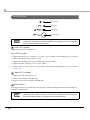
Product Overview
Describes features and general specifications for the product.
Setup
Describes setup and installation of the product and peripherals.
Application Development Information
Describes how to control the printer and necessary information
when you develop applications.
Handling
Describes how to handle the product.
Replacement of the TM-T20
Describes precautions for replacement.
Appendix
Describes interfaces, connectors, and character code tables.
M00056901
Rev. B
Cautions
• No part of this document may be reproduced, stored in a retrieval system, or transmitted in any form
or by any means, electronic, mechanical, photocopying, recording, or otherwise, without the prior
written permission of Seiko Epson Corporation.
• The contents of this document are subject to change without notice. Please contact us for the latest
information.
• While every precaution has been taken in the preparation of this document, Seiko Epson Corporation assumes no responsibility for errors or omissions.
• Neither is any liability assumed for damages resulting from the use of the information contained
herein.
• Neither Seiko Epson Corporation nor its affiliates shall be liable to the purchaser of this product or third
parties for damages, losses, costs, or expenses incurred by the purchaser or third parties as a result of:
accident, misuse, or abuse of this product or unauthorized modifications, repairs, or alterations to this
product, or (excluding the U.S.) failure to strictly comply with Seiko Epson Corporation’s operating
and maintenance instructions.
• Seiko Epson Corporation shall not be liable against any damages or problems arising from the use of
any options or any consumable products other than those designated as Original EPSON Products or
EPSON Approved Products by Seiko Epson Corporation.
Trademarks
EPSON and ESC/POS are registered trademarks of Seiko Epson Corporation in Japan and other
countries/regions.
Microsoft and Windows are registered trademarks of Microsoft Corporation.
ESC/POS® Command System
EPSON ESC/POS is a proprietary POS printer command system that includes patented or patentpending commands. ESC/POS is compatible with most EPSON POS printers and displays.
ESC/POS is designed to reduce the processing load on the host computer in POS environments. It
comprises a set of highly functional and efficient commands and also offers the flexibility to easily make
future upgrades.
Copyright © 2013 Seiko Epson Corporation. All rights reserved.
2
For Safety
Key to Symbols
The symbols in this manual are identified by their level of importance, as defined below. Read
the following carefully before handling the product.
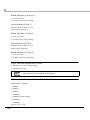
You must follow warnings carefully to avoid serious bodily injury.
WARNING
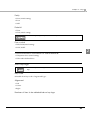
CAUTION
Provides information that must be observed to prevent damage to the equipment or loss of
data.
Possibility of sustaining physical injuries.
Possibility of causing physical damage.
Possibility of causing information loss.
Provides information that must be observed to avoid damage to your equipment or a
malfunction.
Provides important information and useful tips.
3
Warnings
WARNING
4
To avoid risk of electric shock, do not set up this product or handle cables during a
thunderstorm
Never insert or disconnect the power plug with wet hands.
Doing so may result in severe shock.
Handle the power cable with care.
Improper handling may lead to fire or electric shock.
Do not modify or attempt to repair the cable.
Do not place any heavy object on top of the cable.
Avoid excessive bending, twisting, and pulling.
Do not place the cable near heating equipment.
Check that the plug is clean before plugging it in.
Be sure to push the plug all the way in.
Be sure to use the specified power source.
Connection to an improper power source may cause fire or shock.
Do not place multiple loads on the power outlet.
Overloading the outlet may lead to fire.
Shut down your equipment immediately if it produces smoke, a strange odor, or
unusual noise.
Continued use may lead to fire. Immediately unplug the equipment and contact your
dealer or a Seiko Epson service center for advice.
Never attempt to repair this product yourself.
Improper repair work can be dangerous.
Never disassemble or modify this product.
Tampering with this product may result in injury or fire.
Do not allow foreign matter to fall into the equipment.
Penetration by foreign objects may lead to fire.
If water or other liquid spills into this equipment, do not continue to use it.
Continued use may lead to fire. Unplug the power cord immediately and contact your
dealer or a Seiko Epson service center for advice.
Do not use aerosol sprayers containing flammable gas inside or around this
product.
Doing so may cause fire.
Cautions
CAUTION
Do not connect cables in ways other than those mentioned in this manual.
Different connections may cause equipment damage or fire.
Be sure to set this equipment on a firm, stable, horizontal surface.
The product may break or cause injury if it falls.
Do not use this product in locations subject to high humidity or dust levels.
Excessive humidity and dust may cause equipment damage or fire.
Do not place heavy objects on top of this product. Never stand or lean on this
product.
Equipment may fall or collapse, causing breakage and possible injury.
Take care not to injure your fingers on the manual cutter
When you remove printed paper
When you perform other operations such as loading/replacing roll paper
Do not open the roll paper cover without taking the necessary precautions, as this
can result in injury from the autocutter fixed blade.
To ensure safety, unplug this product before leaving it unused for an extended
period.
Restriction of Use
When this product is used for applications requiring high reliability/safety, such as
transportation devices related to aviation, rail, marine, automotive, etc.; disaster prevention
devices; various safety devices, etc.; or functional/precision devices, etc., you should use this
product only after giving consideration to including fail-safes and redundancies into your
design to maintain safety and total system reliability. Because this product was not intended for
use in applications requiring extremely high reliability/safety, such as aerospace equipment,
main communication equipment, nuclear power control equipment, or medical equipment
related to direct medical care, etc., please make your own judgment on this product's suitability
after a full evaluation.
5
About this Manual
Aim of the Manual
This manual was created to provide information on development, design, and installation of
POS systems and development and design of printer applications for developers.
Manual Content
The manual is made up of the following sections:
Chapter 1
Product Overview
Chapter 2
Setup
Chapter 3
Application Development Information
Chapter 4
Handling
Chapter 5
Replacement of the TM-T20
Appendix
Specifications of Interface and Connector
Character Code Tables
6
Contents
■ For Safety...............................................................................................................................3
Key to Symbols ....................................................................................................................................... 3
Warnings ................................................................................................................................................. 4
Cautions.................................................................................................................................................. 5
■ Restriction of Use ..................................................................................................................5
■ About this Manual ................................................................................................................6
Aim of the Manual................................................................................................................................. 6
Manual Content .................................................................................................................................... 6
■ Contents ................................................................................................................................7
Product Overview ........................................................................11
■ Features ...............................................................................................................................11
■ Product Configurations ......................................................................................................12
Interface ............................................................................................................................................... 12
Colors .................................................................................................................................................... 12
Accessories........................................................................................................................................... 12
■ Part Names and Functions.................................................................................................13
Power Switch ........................................................................................................................................ 13
Roll paper cover/Cover open lever .................................................................................................. 13
Control Panel ....................................................................................................................................... 14
Offline .................................................................................................................................................... 15
Connectors........................................................................................................................................... 16
■ Error Status ...........................................................................................................................17
Automatically Recoverable Errors ..................................................................................................... 17
Recoverable Errors............................................................................................................................... 17
Unrecoverable Errors ........................................................................................................................... 18
■ NV Memory (Non-Volatile Memory) ................................................................................19
NV Graphics Memory.......................................................................................................................... 19
User NV Memory .................................................................................................................................. 19
Memory Switches................................................................................................................................. 19
R/E (Receipt Enhancement) .............................................................................................................. 20
User-defined Page ............................................................................................................................... 20
Maintenance Counter ........................................................................................................................ 20
7
■ Product Specifications ....................................................................................................... 21
Printing Specifications..........................................................................................................................22
Character Specifications.....................................................................................................................23
Paper Specifications ............................................................................................................................25
Printable Area.......................................................................................................................................26
Printing and Cutting Positions..............................................................................................................27
Electrical Characteristics.....................................................................................................................28
Environmental Conditions ...................................................................................................................29
External Dimensions and Mass............................................................................................................30
Setup .............................................................................................31
■ Flow of Setup....................................................................................................................... 31
■ Installing the Printer............................................................................................................ 32
Installing the Printer Vertically .............................................................................................................33
Hanging the Printer on a Wall .............................................................................................................34
Attaching Cover on the Power Switch...............................................................................................36
■ Changing the Paper Width................................................................................................ 37
■ Connecting the Printer to the Host Computer ................................................................. 38
For Serial Interface................................................................................................................................38
For USB Interface...................................................................................................................................40
For Ethernet Interface ..........................................................................................................................42
■ Connecting to the Power Source...................................................................................... 44
Connecting the AC cable ..................................................................................................................44
■ Setting the Memory Switches/Receipt Enhancement.................................................... 46
Functions ...............................................................................................................................................47
■ Connecting the Optional External Buzzer........................................................................ 55
Connecting the Buzzer Unit.................................................................................................................56
■ Connecting the Cash Drawer ........................................................................................... 58
Required specifications of cash drawers...........................................................................................58
Connecting the DK cable...................................................................................................................59
Application Development Information......................................61
■ How to Control the Printer.................................................................................................. 61
Selecting a Driver .................................................................................................................................61
ESC/POS Commands ...........................................................................................................................62
■ Software and Manuals ....................................................................................................... 68
Printer Drivers ........................................................................................................................................68
Utilities ....................................................................................................................................................70
How to Get Drivers, Manuals, and the Utility.....................................................................................71
8
■ Setting/Checking Modes...................................................................................................72
Self-test Mode ...................................................................................................................................... 72
NV Graphics Information Print Mode ................................................................................................ 74
Receipt Enhancement Information Print Mode............................................................................... 76
Software Setting Mode ....................................................................................................................... 78
Hexadecimal Dumping Mode ........................................................................................................... 80
Handling .......................................................................................81
■ Installing and Replacing Roll Paper..................................................................................81
■ Removing Jammed Paper.................................................................................................83
■ Cleaning the Printer............................................................................................................85
Cleaning the Printer Case .................................................................................................................. 85
Cleaning the Thermal Head/Platen Roller........................................................................................ 85
■ Preparing for Transport .......................................................................................................86
Replacement of the TM-T20 ........................................................87
■ Additional Functions and Functional Improvements ......................................................87
Print Speed ........................................................................................................................................... 87
Appendix......................................................................................89
■ Specifications of Interface and Connector .....................................................................89
USB (Universal Serial Bus) Interface .................................................................................................... 89
RS-232 Serial Interface ......................................................................................................................... 90
Ethernet Interface................................................................................................................................ 92
■ Setting Conditions for Software Setting Mode..................................................................93
9
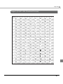
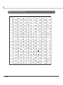
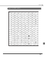
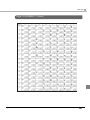
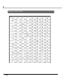
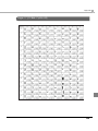
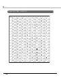
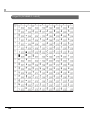
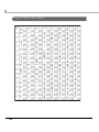
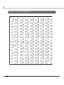
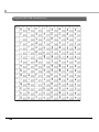
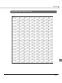
■ Character Code Tables ..................................................................................................... 96
Common to All Pages..........................................................................................................................96
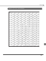
Page 0 [PC437: USA, Standard Europe].............................................................................................97
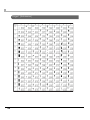
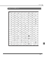
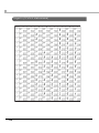
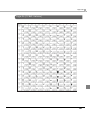
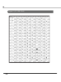
Page 1 (Katakana)...............................................................................................................................98
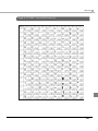
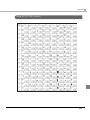
Page 2 (PC850: Multilingual) ...............................................................................................................99
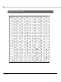
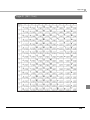
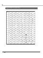
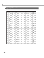
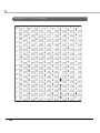
Page 3 (PC860: Portuguese) .............................................................................................................100
Page 4 (PC863: Canadian-French)..................................................................................................101
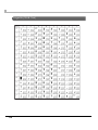
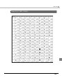
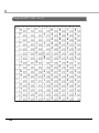
Page 5 (PC865: Nordic) .....................................................................................................................102
Page 11 (PC851: Greek) ....................................................................................................................103
Page 12 (PC853: Turkish)....................................................................................................................104
Page 13 (PC857: Turkish)....................................................................................................................105
Page 14 (PC737: Greek) ....................................................................................................................106
Page 15 (ISO8859-7: Greek) ..............................................................................................................107
Page 16 (WPC1252) ...........................................................................................................................108
Page 17 (PC866: Cyrillic #2) ..............................................................................................................109
Page 18 (PC852: Latin2) ....................................................................................................................110
Page 19 (PC858: Euro) .......................................................................................................................111
Page 20 (KU42: Thai) ..........................................................................................................................112
Page 21 (TIS11: Thai)...........................................................................................................................113
Page 26 (TIS18: Thai)...........................................................................................................................114
Page 30 (TCVN-3: Vietnamese) ........................................................................................................115
Page 31 (TCVN-3: Vietnamese) ........................................................................................................116
Page 32 (PC720: Arabic) ...................................................................................................................117
Page 33 (WPC775: Baltic Rim) ..........................................................................................................118
Page 34 (PC855: Cyrillic) ...................................................................................................................119
Page 35 (PC861: Icelandic) ..............................................................................................................120
Page 36 (PC862: Hebrew) .................................................................................................................121
Page 37 (PC864: Arabic) ...................................................................................................................122
Page 38 (PC869: Greek) ....................................................................................................................123
Page 39 (ISO8859-2: Latin2)...............................................................................................................124
Page 40 (ISO8859-15: Latin9).............................................................................................................125
Page 41 (PC1098: Farsi) .....................................................................................................................126
Page 42 (PC1118: Lithuanian)...........................................................................................................127
Page 43 (PC1119: Lithuanian)...........................................................................................................128
Page 44 (PC1125: Ukrainian).............................................................................................................129
Page 45 (WPC1250: Latin 2) ..............................................................................................................130
Page 46 (WPC1251: Cyrillic) ..............................................................................................................131
Page 47 (WPC1253: Greek)...............................................................................................................132
Page 48 (WPC1254: Turkish) ..............................................................................................................133
Page 49 (WPC1255: Hebrew)............................................................................................................134
Page 50 (WPC1256: Arabic)..............................................................................................................135
Page 51 (WPC1257: Baltic Rim) ........................................................................................................136
Page 52 (WPC1258: Vietnamese) ....................................................................................................137
Page 53 (KZ1048: Kazakhstan) ..........................................................................................................138
Page 255 (User-Defined Page)..........................................................................................................139
International Character Sets.............................................................................................................140
10
Chapter 1 Product Overview
Product Overview
This chapter describes features and general specifications of the product.
Features
Printing
• High speed receipt printing is possible (200 mm/s maximum).
• Shifting from 80 mm width paper printing to 58 mm width paper printing is available.
1
• Paper-saving function is supported.
Handling
• Easy drop-in paper loading
Software
• Command protocol is based on the ESC/POS® Proprietary Command System.
• Windows printer drivers, OPOS ADK, OPOS for .NET ADK, JavaPOS ADK and other drivers
(Linux CUPS, Mac driver) are available.
• Printing of various types of bar codes, GS1-DataBar, and two-dimensional symbols (PDF417,
QR code, MaxiCode, Composite Symbology) is supported.
• A maintenance counter function is supported.
• 42-column mode is supported.
Others
• Various installation layouts (horizontal, vertical, and wall-hanging installation) are selectable.
• Optional external buzzer is available.
11
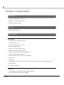
Product Configurations
Interface
• Serial + USB interface model
• Ethernet + USB interface model
• Ethernet interface model
Colors
EDG (Epson Dark Gray)
Accessories
Included
• Roll paper (for operation check)
• Power switch cover
• Power switch waterproof cover
• Wall hanging bracket
• Screws for wall hanging bracket
• Rubber feet for vertical installation
• Control panel label for vertical installation
• 58-mm width paper guide plate
• Interface cable (only for serial + USB model)
• AC adapter
• AC cable
• TM-T20II Software & Documents Disc containing drivers, utilities, and documentation
• Setup Guide
• Warranty certificate
Options
• Affixing tape for fixing the printer (Model: DF-10)
• External buzzer unit (Model: OT-BZ20)
12
Chapter 1 Product Overview
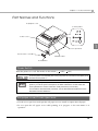
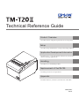
Part Names and Functions
Roll paper cover
Control panel
Cutter cover
1
Cover open lever
Power switch cover
Manual cutter
Power switch
Power Switch
Turns the printer on or off. The marks on the switch: (
: OFF/
: ON)
To turn the printer on immediately after turning the printer off, wait until the LED lights go off,
and then turn the power on.
Before turning the printer off, it is recommended to send a power-off command to the
printer. If you use the power-off sequence, the latest maintenance counter values are
saved. (Maintenance counter values are usually saved every two minutes.)
For information about ESC/POS commands, see the ESC/POS Quick Reference or the
ESC/POS Command Reference.
Roll paper cover/Cover open lever
• Use the cover open lever and open the roll paper cover to install or replace the roll paper.
• Do not open the roll paper cover while printing is in progress or the auto-cutter is in
operation.
13
Control Panel
Power LED
Error LED
Paper LED
Feed button
When installing the printer vertically or hanging the printer on a wall, be sure to attach the
included control panel label for vertical installation on the roll paper cover. The control panel
label for vertical installation is upside down.
Power LED (green)
Lights when the power supply is on.
Error LED (orange)
• Lights after the power is turned on or after a reset (offline). Automatically goes out after a
while to indicate that the printer is ready.
• Lights when printing has stopped (offline) due to paper end.
• Lights when the roll paper cover is open (offline).
• Flashes when an error occurs. (For information about the flashing patterns, see "Error Status"
on page 17.)
Paper LED (orange)
• Lights when the roll paper is out.
• Flashes when Self-test standby state.
• Flashes when macro execution standby state.
Feed button
Pressing this button once feeds the roll paper by one line. Holding this button down feeds the
roll paper continuously.
Enabling/disabling of Feed button can be selected by a command. If the command is set to
disable this button, it does not function. For information about ESC/POS commands, see
the ESC/POS Quick Reference or the ESC/POS Command Reference.
14
Chapter 1 Product Overview
Offline
The printer automatically goes offline under the following conditions:
• During power on until the printer is ready
• During the self-test
• While roll paper is fed using the Feed button
• When the roll paper cover is open
• When the printer stops printing due to a paper end
• During a macro execution standby state
• When an error has occurred (See "Error Status" on page 17.)
1
15
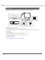
Connectors
All cables are connected to the connector panel on the lower rear of the printer.
UIB
(Universal interface board)
DK (Drawer kickout) connector
RS-232
10BASE-T/100BASE-TX
Power supply
connector
USB
(Built-in)
• DK (Drawer kick-out) connector:
Connects the cash drawer or the optional external buzzer.
See "Connecting the Cash Drawer" on page 58, and "Connecting the Optional External Buzzer"
on page 55.
• Interface connector:
Connects the printer with the host computer interface.
See "Connecting the Printer to the Host Computer" on page 38.
• Power supply connector:
Connect the AC adapter.
See "Connecting to the Power Source" on page 44.
16
Chapter 1 Product Overview
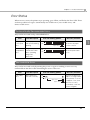
Error Status
When an error occurs, the printer stops operating, goes offline, and flashes the Error LED. There
are three possible error types: automatically recoverable errors, recoverable errors, and
unrecoverable errors.
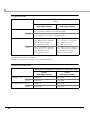
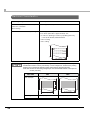
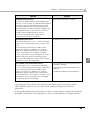
Automatically Recoverable Errors
They can be recovered easily, as described below.
Error
Error description
Roll paper
cover open
error
The roll paper cover
was opened during
printing.
Print head
temperature
error
A high temperature
outside the head
drive operating
range was
detected.
Error LED flashing pattern
Recovery measure
Approx. 160 ms
Recovers automatically
when the roll paper
cover is closed.
Approx. 160 ms
Recovers automatically
when the print head
cools.
LED ON
LED OFF
LED ON
LED OFF
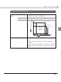
Recoverable Errors
They can be recovered easily by turning the power on again or sending an error recovery
command from the driver after eliminating the cause of the error.
Error
Autocutter
error
Error description
Autocutter does
not work correctly.
Error LED flashing pattern
LED ON
LED OFF
Approx. 2.56 s
Approx. 160 ms
Recovery measure
Remove the jammed
paper or foreign matter
in the printer, close the
roll paper cover, send
the error recovery
command, or turn the
power on again.
17
1
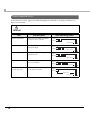
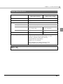
Unrecoverable Errors
If the same error occurs again even after turning the power back on, contact your dealer or a
Epson service center.
Turn off the power immediately when an unrecoverable error occurs.
CAUTION
Error
Memory R/W error
Error description
After R/W checking, the printer
does not work correctly.
Error LED flashing pattern
LED ON
LED OFF
Approx. 160 ms
High voltage error
The power supply voltage is
extremely high.
LED ON
LED OFF
Approx. 160 ms
Low voltage error
The power supply voltage is
extremely low.
LED ON
LED OFF
Approx. 160 ms
CPU execution error
The CPU is executing an
incorrect address.
LED ON
LED OFF
Approx. 160 ms
Internal circuit
connection error
Internal circuits are not
connected correctly.
LED ON
LED OFF
Approx. 2.56 s
Approx. 160 ms
18
Chapter 1 Product Overview
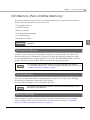
NV Memory (Non-Volatile Memory)
The printer's NV memory stores data even after the printer power is turned off. NV memory
contains the following memory areas for the user:
• NV graphics memory
• User NV memory
• Memory switches
• R/E (Receipt Enhancement)
• User-defined page
• Maintenance counter
As a guide, NV memory rewriting should be used 10 times or less a day when you program
applications.
NV Graphics Memory
Graphics, such as shop logos to be printed on receipts, can be registered. Even with a serial
interface model whose communication speed is low, high speed graphic printing is possible.
Use the TM-T20II Utility to register graphics. You can also use the TM-T20II Utility or the NV
graphics information print mode to print and confirm the registered graphics.
For information about the TM-T20II Utility, see the TM-T20II Utility User’s Manual.
For information about how to use the NV graphics information print mode, see "NV
Graphics Information Print Mode" on page 74.
User NV Memory
You can store and read text data for multiple purposes, such as for storing a note including
customizing or maintenance information of the printer.
Use ESC/POS commands to store and read the text data.
For information about ESC/POS commands, see the ESC/POS Quick Reference or the
ESC/POS Command Reference.
Memory Switches
With the memory switches, which are software switches for the printer, you can configure
various settings of the printer. For information about the memory switch, see "Setting the
Memory Switches/Receipt Enhancement" on page 46.
19
1
R/E (Receipt Enhancement)
Graphics, such as shop logos can be printed on top or bottom of receipts by setting R/E (Receipt
Enhancement). For information about R/E, see "Setting the Memory Switches/Receipt
Enhancement" on page 46.
User-defined Page
You can store character data in the user-defined page (character code table: page 255) so that you
can also print characters not resident in the printer.
For the character code table, see "Character Code Tables" on page 96.
Maintenance Counter
With this function, printer information, such as the number of lines printed, the number of
autocuts, and printer operation time after the printer starts working, is automatically stored in
NV memory. You can read the information with the Status API of the APD, OPOS ADK, or ESC/
POS commands to use it for periodical checks or part replacement.
You can also check the head running length and number of times of autocutting with the
self-test (see "Self-test Mode" on page 72.) and the TM-T20II Utility.
20
Chapter 1 Product Overview
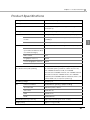
Product Specifications
Printing method
Thermal line printing
Printing direction
Unidirectional with friction feed
Paper feed speed
200 mm/s {7.87"/s} (continuous paper feeding with the
Feed button)
Cutting method
Partial cut (cutting with one point in left edge left uncut)
Interface
Serial + USB interface models
Serial (RS-232), USB [USB 2.0, Full-speed (12 Mbps)]
Ethernet + USB interface
models
Ethernet (10BASE-T/100BASE-TX), USB [USB 2.0, Full-speed
(12 Mbps)]
Ethernet interface models
Ethernet (10BASE-T/100BASE-TX)
Receive buffer
4 KB/45 bytes (selectable using the memory switch)
Downloaded buffer
(user-defined characters and
user-defined images)
12 KB
Macro buffer
2 KB
NV graphics memory
256 KB
Download graphics memory
208 KB
User NV memory
1KB
Buffers
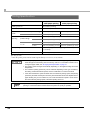
1
Barcode/
two-dimensional symbol printing
UPC-A, UPC-E, JAN 8 (EAN 8), JAN 13 (EAN 13), CODE 39,
ITF, CODABAR (NW-7), CODE 93, CODE 128, GS1-128,
GS1 DataBar Omnidirectional, GS1 DataBar
Truncated,GS1 DataBar Stacked, GS1 DataBar Stacked
Omnidirectional,GS1 DataBar Limited, GS1 DataBar
Expanded,GS1 DataBar Expanded Stacked, PDF417, QR
CODE, MaxiCode, Composite Symbology
Operating voltage
DC 24V ± 7%
Life
Printer mechanism
15,000,000 lines (printing + paper feeding)
Thermal head
100 million pulses,100 km
Autocutter
1,500,000 cuts
MTBF
360,000 hours
MCBF
60,000,000 lines
Overall dimensions (H × W × D)
146 × 140 × 199 mm {5.75 × 5.51 × 7.83"}
Weight (mass)
Approx. 1.7 kg {3.74 lb}
21
Printing Specifications
80 mm
width paper printing
Printing method
Thermal line printing
Dot density
203 × 203 dpi
Paper
width
Character
spacing
58 mm
width paper printing
Standard mode (initial setting)
72.0 mm {2.83"}, 576 dots
52.5 mm {2.07"}, 420 dots
42 column mode
68.3 mm {2.69"}, 546 dots
47.3 mm {1.86"}, 378 dots
Standard mode
(initial setting)
Font A
0.25 mm {0.0098"} (2 dots)
Font B
0.25 mm {0.0098"} (2 dots)
42 column
mode
Font A
0.38 mm {0.015"} (3 dots)
0.25 mm {0.0098"} (2 dots)
Font B
0.25 mm {0.0098"} (2 dots)
0.25 mm {0.0098"} (2 dots)
Line spacing
3.75 mm {1/5"} (initial setting, programmable by
command)
Maximum print speed*
200 mm/s {7.87"/s}
dpi: dots per inch
*: when the printer prints with the standard print density level at 25°C {77°F} and 24V.
To change the paper width, you need to install the 58-mm width paper guide plate and to
make the paper width setting with the memory switch. For information about how to
change the paper width, see "Changing the Paper Width" on page 37.
The printing speed changes automatically depending on the applied voltage and head
temperature.
The maximum printing speed may not be achieved depending on the type of interface,
the setting of data transmission speed, and the combination of control commands.
If the data transmission speed is slower than the maximum printing speed, the printing
speed may fluctuate and the print result may become shaded and/or dot displacement in
paper feeding may occur.Furthermore, if the data transmission speed is much slower
than the maximum printing speed, intermittent printing will occur.
Especially when using a serial interface, low transmission speed may cause intermittent
printing. It is recommended to transmit data to the printer as quickly as possible.
22
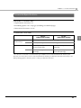
Chapter 1 Product Overview
Character Specifications
Number of characters
• Alphanumeric characters: 95
• Extended graphics: 128 × 43 pages (including user-defined page)
• International characters: 18 sets
Character structure
80 mm
width paper printing
58 mm
width paper printing
1
Standard mode
(initial setting)
Font A
12 × 24 (including 2-dot horizontal spacing)
Font B
9 × 17 (including 2-dot horizontal spacing)
42 column mode
Font A*
13 × 24 (including 3-dot
horizontal spacing)
9 × 17 (including 2-dot horizontal
spacing)
Font B
9 × 17 (including 2-dot horizontal
spacing)
12 × 24 (including 2-dot
horizontal spacing)
*: 13 × 24 font is a font with a 1-dot horizontal space added to Font A of the standard mode. Therefore, the
character size is the same as Font A of the standard mode and the space between characters increases by 1 dot.
When printing graphics characters, there is 1-dot space between characters.
23
Character size
Standard/Double-height/Double-width/Double-width, double-height
W×H
80 mm
width paper printing
Standard mode
42 column mode
58 mm
width paper printing
Font A
1.25 × 3.00 mm/1.25 × 6.00 mm/2.50 × 3.00 mm/2.50 × 6.00 mm
{0.05 × 0.12"/0.05 × 0.24"/0.10 × 0.12"/0.10 × 0.24"}
Font B
0.88 × 2.13 mm/0.88 × 4.26 mm/1.76 × 2.13 mm/1.76 × 4.26 mm
{0.03 × 0.08"/0.03 × 0.17"/0.07 × 0.08"/0.07 × 0.17"}
Font A
1.25 × 3.00 mm/1.25 × 6.00 mm/
2.50 × 3.00 mm/2.50 × 6.00 mm
{0.05 × 0.12"/0.05 × 0.24"/
0.10 × 0.12"/0.10 × 0.24"}
0.88 × 2.13 mm/0.88 × 4.26 mm/
1.76 × 2.13 mm/1.76 × 4.26 mm
{0.03 × 0.08"/0.03 × 0.17"/
0.07 × 0.08"/0.07 × 0.17"}
Font B
0.88 × 2.13 mm/0.88 × 4.26 mm/
1.76 × 2.13 mm/1.76 × 4.26 mm
{0.03 × 0.08"/0.03 × 0.17"/
0.07 × 0.08"/0.07 × 0.17"}
1.25 × 3.00 mm/1.25 × 6.00 mm/
2.50 × 3.00 mm/2.50 × 6.00 mm
{0.05 × 0.12"/0.05 × 0.24"/
0.10 × 0.12"/0.10 × 0.24"}
Note:
Space between characters is not included.
Characters can be scaled up to 64 times as large as the standard sizes.
Characters per line
Standard/Double-height/Double-width/Double-width, double-height
80 mm
width paper printing
Standard mode
42 column mode
24
58 mm
width paper printing
Font A
48/48/24/24
35/35/17/17
Font B
64/64/32/32
46/46/23/23
Font A
42/42/21/21
42/42/21/21
Font B
60/60/30/30
31/31/15/15
Chapter 1 Product Overview
Paper Specifications
80 mm
width paper printing
Paper types
Specified thermal paper
Form
Roll paper
Size
58 mm
width paper printing
Roll paper diameter
83 mm {3.27"} maximum
Roll paper core
Inside: 12 mm {0.47"}, Outside: 18 mm {0.71"}
Roll width when taken up
80 + 0.5/-1.0 mm
{3.15 + 0.02/-0.04"}
58 + 0.5/-1.0 mm
{2.28 + 0.02/-0.04"}
Paper width
79.5 ± 0.5 mm {3.13 ± 0.02"}
57.5 ± 0.5 mm {2.26 ± 0.02"}
Specified roll paper type
NTP080-80
NTP058-80
Specified original paper type
TF50KS-E, TF60KS-E (NIPPON Paper Industries Co., Ltd.)
1
PD150R, PD160R, PD190R (OJI Paper Mfg. Co., Ltd.)
P220AGB-1 (Mitsubishi Paper Mills Limited.)
P350 (Kanzaki Specialty Papers)
AF50KS-E (Jujo Thermal Oy)
F5041 (Mitsubishi HiTec Paper Flensburg GmbH)
KT55F20, KT48F20 (Koehler Paper Group)
Paper must not be pasted to the roll paper core.
25
Printable Area
80 mm paper width printing
The maximum printable area of paper with a width of 79.5 ± 0.5 mm is 72.0 ± 0.2 mm (576 dots)
and the approximate space is 3.0 mm on the left side on the left side and 4.5 mm on the right side.
79.5 ± 0.5 mm {3.13 ± 0.02”}
72.0 ± 0.2 mm {2.83 ± 0.008”}
3.0 mm {0.12”}
4.5 mm {0.18”}
58 mm paper width printing
The maximum printable area of paper with a width of 57.5 ± 0.5 mm is 52.5 ± 0.2 mm (420 dots),
and the approximate space is 3.0 mm on the left side and 2.0 mm on the right side.
57.5 ± 0.5 mm {2.26 ± 0.02”}
52.5 ± 0.2 mm {2.07 ± 0.008”}
3.0 mm {0.12”}
26
2.0 mm {0.079”}
Chapter 1 Product Overview
Printing and Cutting Positions
Manual-cutter position
Approx. 27.1 mm {1.07"}
Autocutter blade position
Approx. 10.5 mm {0.41"}
1
Center of the print dotline
Paper feed direction
The values above may vary slightly as a result of paper slack or variations in the paper.
Take this into account when setting the cutting position of the autocutter.
27
Electrical Characteristics
Operating voltage
DC 24V ± 7%
Current consumption
Standby
Mean: Approximately 0.1 A
(24V, 25°C, standard
print density)
Operating
Mean: Approximately 1.8 A
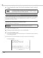
Note: When print ratio is approximately 18%
Continuous printing for 50 lines (repeating 20H-7FH)
Font A, 48 columns, ASCII character
5 line feeding
Autocutting
ABCDE
BCDE
6789
67890
48 columns
If printing is continuously performed with a high ratio, the overcurrent protection may be
activated and result in uneven print density or a low voltage error. Therefore, the printing
length must not exceed the following values when printing with high print ratio.
Print ratio: Number of dots being energized per one dot line/Total number of dots per one
dot line (576 dots)
Print ratio
80%
100%
Print example
58 mm {2.28"}
Print length
28
30 mm {1.18"}
72 mm {2.83"}
20 mm {0.79"}
Chapter 1 Product Overview
Environmental Conditions
Temperature/
Humidity
Operating
5 to 45°C {41 to 113°F}, 10 to 90% RH (See the operating
temperature and humidity range below.)
Storage
-10 to 50°C {14 to 122°F}, 10 to 90% RH (except for paper)
Relative humidity
[%RH]
34°C, 90%
90
80
40°C, 65%
60
Operating
environment
range
40
45°C, 50%
1
20
10
0
Acoustic noise (operating)
0
10
20
30
40
50 [°C]
Ambient temperature
Approximately 55 dB (bystander position)
Note:
The values above are measured in the Epson evaluation
condition.
Acoustic noise differs depending on the paper used, printing
contents, and the setting values, such as print speed or print
density.
29
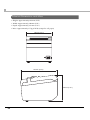
External Dimensions and Mass
• Height: Approximately 146 mm {5.75"}
• Width: Approximately 140 mm {5.51"}
• Depth: Approximately 199 mm {7.83"}
• Mass: Approximately 1.7 kg {3.74 lb} (except for roll paper)
140 mm {5.51"}
199 mm {7.83"}
146 mm {5.75"}
30
Chapter 2 Setup
Setup
This chapter describes setup and installation of the product and peripherals.
Flow of Setup
This chapter consists of the following sections along with the setup flow of the product and
peripherals.
1. Installing the Printer (page 32)
2. Changing the Paper Width (page 37)
2
3. Connecting the Printer to the Host Computer (page 38)
4. Connecting to the Power Source (page 44)
5. Setting the Memory Switches/Receipt Enhancement (page 46)
6. Connecting the Optional External Buzzer (page 55)
7. Connecting the Cash Drawer (page 58)
31
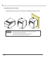
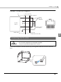
Installing the Printer
You can install the printer horizontally on a flat surface (with the paper exit on top) or vertically
(with the paper exit at the front). Also, you can hang it on a wall using the included accessories.
Horizontal installation
Vertical installation
Hanging on a wall
Take measures to prevent the printer from moving by vibration during paper cutting and
when using a drawer. Affixing tape (Model: DF-10) is provided as an option.
Do not place the printer in dusty locations.
Do not knock or strike the printer. This may cause defective print.
Do not catch cables or foreign matter under the printer.
32
Chapter 2 Setup
Installing the Printer Vertically
When installing the printer vertically, be sure to attach the included control panel label for
vertical installation on the roll paper cover, and attach 4 rubber feet in the rectangular indents in
the printer case, as shown in the illustration below.
Control panel label for
vertical installation
Rubber feet
Vertical installation
You can install the printer so that the roll paper cover is upright to the mounting surface using
the included wall hanging bracket.
1
2
3
4
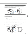
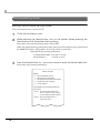
Attach the control panel label for vertical installation on the roll paper
cover.
Install the wall hanging bracket on the printer, and fix it using 2 included
screws.
Attach 2 rubber feet in the rectangular indents in the printer case, and
attach 2 rubber feet within the scribed line on the hanging bracket.
Place the printer with the wall-hanging-bracket-side down.
3
Control panel label
for vertical installation
Rubber feet
1
207 mm
{8.15"}
2
Wall hanging
bracket
33
2
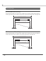
Hanging the Printer on a Wall
To hang the printer on the wall, follow the steps below.
To fix the printer securely, hang the printer on a wall made of wood, concrete, or metal.
The thickness of the wall should be 10 mm or more.
Be sure to use metallic screws.
The screws on the wall side must have a pull-out strength of 150 N (15.3 kgf) or more.
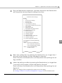
1
Attach the included control panel label for vertical installation on the roll
paper cover.
Control panel label
for vertical installation
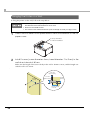
2
Install 2 screws (screw diameter: 4 mm, head diameter: 7 to 9 mm) in the
wall at an interval of 80 mm.
Make sure the length of the screw's body in the wall is 10 mm or more, and the length outside the wall is 3 to 4 mm.
R
3 - 4 mm
{0.12 - 0.16"}
80 mm
{3.15"}
7 - 9 mm
{0.28 - 0.35"}
4 mm
{0.16"}
10 mm {0.39"}
or more
34
Chapter 2 Setup
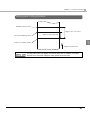
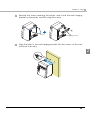
3
Remove the screws retaining the printer case, install the wall hanging
bracket on the printer, and fix it using the screws.
Screws
Wall hanging bracket
4
Align the holes in the wall hanging bracket with the screws on the wall,
and hook it securely.
2
35
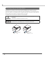
Attaching Cover on the Power Switch
Install the power switch cover that comes with the TM-T20II onto the printer to prevent
inadvertent operation of the power switch and to prevent tampering. To reset the printer when
the power switch cover is installed, insert a long, thin object (such as the end of a paper clip) into
the hole in the power switch cover and press the power switch.
A waterproof cover for the power switch can also be attached.
WARNING
If an accident occurs with the power switch cover attached, unplug the AC cable
immediately.
Continued use of the printer may cause fire or shock.
Use the power switch waterproof cover if the printer is installed in a humid location or
exposed to water. If current leakage occurs, it could result in electric shock.
To use these covers, install them as shown in the illustration below.
Power switch
cover
36
Power switch
waterproof cover
Chapter 2 Setup
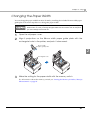
Changing the Paper Width
You can change the paper width from 80 to 58 mm by installing the included 58-mm width paper
guide plate. Follow the steps below to change the paper width.
Because some parts of the print head and the autocutter contact the platen and they may
become worn out, once you change the paper width from 80 to 58 mm and use the printer,
you cannot change it back to 80 mm.
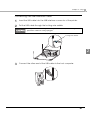
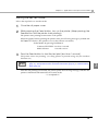
1
2
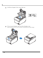
Open the roll paper cover.
Align 3 projections on the 58-mm width paper guide plate with the
rectangular holes in the printer, and push it downwards.
58-mm width
paper guide plate
2
Rectangular holes
3
Make the setting for the paper width with the memory switch.
For information about the memory switch, see "Setting the Memory Switches/Receipt
Enhancement" on page 46.
37
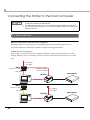
Connecting the Printer to the Host Computer
The printer uses a modular connector specifically designed for the cash drawer. Do not
connect the connector to a telephone line.
For USB interface models, do not turn on the printer before installing the printer driver.
For Ethernet interface models, do not connect a telephone line or DK cable to the
Ethernet connector.
For Serial Interface
Serial interface connection diagram
When this printer is connected to a host computer by the serial interface, there are two
connection methods; stand alone connection and pass-through connection.
Stand alone connection
This printer is connected to the host computer directly via the serial port. When a customer
display (DM-D) is to be connected, connect it to the host computer via the serial port or USB
port.
AC Adapter
+ AC cable
DM-D
(Serial I/F model)
Extension cable
for power supply
Serial cable
Cash drawer
TM-T20II
Serial cable
DK cable
DM-D
(USB I/F model)
AC Adapter
+ AC cable
USB cable
Cash drawer
TM-T20II
Serial cable
38
DK cable
Chapter 2 Setup
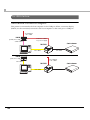
Pass-through connection
This printer is connected to the host computer through the serial interface via the customer
display (DM-D).
AC Adapter
+ AC cable
Extended
power cable
DK cable
Serial cable
Serial cable
DM-D
TM-T20II
Cash drawer
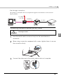
Connecting the serial interface (RS-232) cable
Be sure to turn off the power supply for both the printer and host computer before
connecting the cables.
WARNING
1
2
3
2
Insert the serial cable connector firmly into the serial interface
connector.
When using connectors equipped with screws, tighten them to secure
the connectors firmly.
Connect the other end of the serial cable to the host computer.
39
For USB Interface
USB interface connection diagram
This printer is connected to the host computer via the USB port. When a customer display
(DM-D) is to be connected, connect it to the host computer via the serial port or USB port.
AC Adapter
+ AC cable
DM-D
(Serial I/F model)
Extension cable
for power supply
Serial cable
Cash drawer
TM-T20II
USB cable
DK cable
DM-D
(USB I/F model)
AC Adapter
+ AC cable
USB cable
Cash drawer
TM-T20II
USB cable
40
DK cable
Chapter 2 Setup
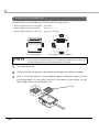
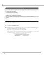
Connecting the USB interface cable
1
Insert the USB cable into the USB interface connector of the printer.
2
Put the USB cable through the locking wire saddle.
Putting the USB cable through the locking wire saddle, as shown in the figure below,
prevents the cable from coming unplugged.
Locking wire saddle
2
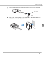
3
Connect the other end of the USB cable to the host computer.
41
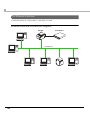
For Ethernet Interface
Connect the printer to a network by a LAN cable via a hub.
Ethernet interface connection diagram
TM-T20II
Cash drawer
DK cable
10/100BASE-T
42
Chapter 2 Setup
Connecting the LAN cable
CAUTION
When LAN cables are installed outdoors, make sure devices without proper surge
protection are cushioned by being connected through devices that do have surge
protection.
Otherwise, the devices can be damaged by lightning.
Never attempt to connect the customer display cable, DK cable, or a telephone
line cable to the 10/100BASE-T LAN connector.
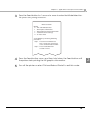
To use the Ethernet interface, EpsonNet Config is required. For detailed information about
the setup methods, see the EpsonNet Config Operations Guide.
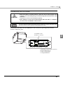
Connect the LAN cable to the 10/100BASE-T LAN connector by pressing firmly until the
connector clicks into place.
10/100BASE-T LAN
interface connector
2
NOT FOR TELECOMMUNICATION USE
KEIN TELEFONANSCHLUSS M6
LED (Green)
LED (Yellow)
Button
A push button is provided to perform
the following functions.
Status sheet printing
Setting initialization
43
Connecting to the Power Source
WARNING
Never insert the AC cable plug into a socket that does not meet the rated voltage
requirements of the printer.
Doing so may result in damage to the printer.
Should a fault ever occur, immediately turn off the power to the printer and unplug
the AC cable from the wall socket.
Connecting the AC cable
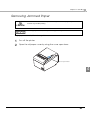
1
Make sure the printer is turned off.
2
Connect the AC cable to the AC adapter.
AC adapter
AC cable
3
44
Connect the DC cable of the AC adapter to the power supply
connector.
Chapter 2 Setup
4
Insert the AC plug into a wall socket.
2
45
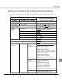
Setting the Memory Switches/Receipt Enhancement
With the memory switch and R/E (receipt enhancement) function, which are software settings
for this printer, you can set the various functions.
For an outline of the functions, see the following section. Use the methods shown in the table
below; TM-T20II Utility, Software Setting Mode, or ESC/POS commands, to set the memory
switches and R/E functions.
Software
Setting Mode
ESC/POS
Commands
Receive buffer capacity
✔
✔
BUSY condition
✔
✔
Processing when data receive error
✔
✔
USB power-saving function
✔
✔
Release condition of receive buffer BUSY
✔
✔
TM-T20II
Utility
Paper width
✔
✔
✔
Print density
✔
✔
✔
Print speed
✔
✔
✔
Character code table default
✔
✔
✔
International character default
✔
✔
✔
Interface selection*1
✔
✔
✔
Power supply unit capacity
✔
✔
✔
Number of columns
✔
✔
✔
Autocutting after closing cover
✔
✔
✔
Paper reduction
✔
✔
✔
Font A auto replacement
✔
✔
Font B auto replacement
✔
✔
Optional buzzer
✔
✔
✔
Logo 180 dpi emulation mode
✔
✔
✔
Communication condition of serial interface
✔
✔
✔
Communication condition of USB interface
✔
✔
✔
Receipt
Enhancement
Memory Switches
Customized Values
Item\Method
Auto top logo
Auto bottom logo
Auto top/bottom logo extended functions
dpi: dots per inch
*1: Enabled only for serial + USB model, and ethernet + USB model
*2: Excluding some function.
46
✔*2
✔
✔
✔
✔*2
✔
Chapter 2 Setup
For information about the TM-T20II Utility, see the TM-T20II Utility User’s Manual.
For information about how to use the software setting mode, see "Software Setting
Mode" on page 78.
For information about ESC/POS commands, see the ESC/POS Quick Reference or the
ESC/POS Command Reference.
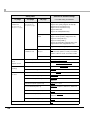
Functions
Receive buffer capacity
• 4KB (initial setting)
• 45 bytes
BUSY condition
2
• Receive buffer full/Offline (initial setting)
• Receive buffer full
Processing when data receive error
• Prints “?” (initial setting)
• Ignored
USB power-saving function
• Disabled
• Enabled (initial setting)
The USB power-saving function is valid only when the USB interface communication
condition is set to the vendor-defined class and the system configuration is set so that the
USB driver can support the USB power-saving function.
Release condition of receive buffer BUSY
• Releases when the remaining receive buffer capacity becomes 256 bytes (initial setting)
• Releases when the remaining receive buffer capacity becomes 138 bytes
This function is enabled only when Receive buffer capacity is set to 4KB.
47
Paper width
• 80 mm (initial setting)
• 58 mm
To change the paper width, you need to install the 58-mm width paper guide plate. For
information about how to change the paper width, see "Changing the Paper Width" on page
37.
Print density
Selectable from levels 1 to 7 (85% 115%).
Initial setting: level 4 (100%)
Depending on the paper type, it is recommended to set the print density as shown in the table
below for the best print quality.
Original Paper type
Density Level
TF50KS-E, TF60KS-E, PD150R, PD160R, PD190R,
P220AGB-1, P350, AF50KS-E, KT55F20, KT48F20
4 (100%)
F5041
5 (105%)
When the print density level is increased, printing speed may be reduced.
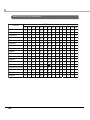
Print speed
Selectable from levels 1 to 13 (Slow Fast)
Initial setting: level 13
Depending on print conditions, such as print duty, print head temperature, and data
transmission speed, print speed is automatically adjusted, which may cause white lines due
to intermittent print (the motor sometimes stops). To avoid this, keep the print speed
constant by setting it lower, or set the transmission speed higher for the serial interface.
48
Chapter 2 Setup
Character code table default
Selectable from 43 pages including user defined page
Initial setting: Page 0 (PC437: USA, Standard Europe)
For the character code table, see "Character Code Tables" on page 96.
International character default
Selectable from 18 sets
Initial setting: USA
For the character code table, see "International Character Sets" on page 140.
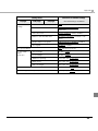
Interface selection (only for serial + USB model, and ethernet + USB
model)
The tables below describe the modes you can set for the printer to control the dual interfaces.
Automatic selection:
The interface for UIB (Universal Interface Board) or Built-in USB to which data is transmitted
first is selected.
When using the Ethernet + USB model, however, the built-in USB is not available for Automatic
selection mode. Select "Fixed to built-in USB" to use the USB interface.
The selected interface is enabled until the power is turned off or the printer is reset.
For serial + USB interface models
Interface mode
Serial
Built-in USB
Automatic selection (initial setting)
Available
Available
Fixed to serial
Available
Not available
Not available
Available
Fixed to built-in USB
For ethernet + USB interface models
Interface mode
Ethernet
Built-in USB
Automatic selection (initial setting)
Available
Not available
Fixed to ethernet
Available
Not available
Not available
Available
Fixed to built-in USB
49
2
Power supply unit capacity
Selectable from levels 1 to 3 (Low High)
Initial setting: level 3
Number of columns
• Standard mode (initial setting)
• 42 column mode
Autocutting after closing cover
• Cuts (initial setting)
• Does not cut
Paper reduction
Extra upper space reduction
• Disabled (initial setting)
• Enabled
Extra lower space reduction
• Disabled (initial setting)
• Enabled
Line space reduction rate
• Not reduced (initial setting)
• 25%
• 50%
• 75%
Line feed reduction rate
• Not reduced (initial setting)
• 25%
• 50%
• 75%
50
Chapter 2 Setup
Barcode height reduction rate
• Not reduced (initial setting)
• 25%
• 50%
• 75%
Font A auto replacement
• Does not replace (initial setting)
• Font B
This function is enabled only when Number of columns is set to Standard mode.
Font B auto replacement
2
• Does not replace (initial setting)
• Font A
This function is enabled only when Number of columns is set to Standard mode.
Optional buzzer
For information about how to connect the optional external buzzer, see "Connecting the
Optional External Buzzer" on page 55.
When the optional external buzzer is enabled, a cash drawer cannot be used. Be sure to
disable it when you use a cash drawer.
Enables/disables
• Disabled (initial setting)
• Enabled
Buzzer frequency (Error)
• Does not sound
• Sounds 1 time
• Sounds continuously (initial setting)
Sound pattern (Autocut)
Selectable from Patterns A to E
Initial setting: Pattern A
51
Buzzer frequency (Autocut)
• Does not sound
• Sounds 1 time (initial setting)
Sound pattern (Pulse 1)
Selectable from Patterns A to E
Initial setting: Pattern A
Buzzer frequency (Pulse 1)
• Does not sound
• Sounds 1 time (initial setting)
Sound pattern (Pulse 2)
Selectable from Patterns A to E
Initial setting: Pattern B
Buzzer frequency (Pulse 2)
• Does not sound
• Sounds 1 time (initial setting)
Logo 180 dpi emulation mode
• Standard logo mode (initial setting)
• 180 dpi logo mode
Set to 180 dpi logo mode when you register graphics for 180 dpi so that the print result (203
dpi) is the same as one printed with a 180 dpi printer.
Communication condition of serial interface
Transmission speed
• 2400 bps
• 4800 bps
• 9600 bps
• 19200 bps
• 38400 bps (initial setting)
• 57600 bps
• 115200 bps
[bps: bits per second]
52
Chapter 2 Setup
Parity
• None (initial setting)
• Even
• Odd
Data bit
• 7 bits
• 8 bits (initial setting)
If set to 7 bits, printing from a printer driver is not possible.
Flow control
• DTR/DSR (initial setting)
• XON/XOFF
2
Communication condition of USB interface
• USB printer class (initial setting)
• USB vendor-defined class
Auto top logo
TM-T20II Utility does not support the function for Number of lines to be deleted below top
logo.
Key-code
Selectable from key-codes of registered logos
Alignment
• Left
• Center
• Right
Number of lines to be deleted below top logo
53
Auto bottom logo
Key-code
Selectable from key-codes of registered logos
Alignment
• Left
• Center
• Right
Auto top/bottom logo extended functions
TM-T20II Utility does not support the following functions.
Top logo print while paper feeding to the cutting position
Top logo print while clearing the buffer to recover from a recoverable error
Top logo print after paper feeding with the Feed button has finished
Top logo print while paper feeding to the cutting position
• Disabled (initial setting)
• Enabled
Top logo print when printer is powered on
• Disabled (initial setting)
• Enabled
Top logo print when roll paper cover is closed
• Disabled
• Enabled (initial setting)
Top logo print while clearing the buffer to recover from a recoverable error
• Disabled
• Enabled (initial setting)
Top logo print after paper feeding with the Feed button has finished
• Disabled (initial setting)
• Enabled
54
Chapter 2 Setup
Connecting the Optional External Buzzer
When the optional external buzzer (model: OT-BZ20) is connected to the DK connector of the
printer, you can set the printer so that it beeps when you send commands, when an error occurs,
when executed autocutting, and when detected paper end. Settings for sound patterns and
frequency depending on the occasions the buzzer beeps are also available.
You need to set the memory switches for buzzer enable/disable setting, sound pattern setting,
and frequency setting. For information about the memory switches, see "Setting the Memory
Switches/Receipt Enhancement" on page 46.
Be sure to turn off the printer before you connect/disconnect the optional external
buzzer.
Do not connect both the optional external buzzer and the cash drawer to the printer at
the same time by using a branched connector.
2
Volume adjustment knob
55
Connecting the Buzzer Unit
The buzzer unit is recommended to be installed in the following positions.
• When using the printer horizontally: either side
• When using the printer vertically:
side or top
• When using the printer on the wall:
side, top, or bottom
Horizontal installation
Vertical/Wall-hanging installation
Do not install the buzzer unit at the roll paper exit.
To prevent liquid from entering inside, it is recommended to install the buzzer unit so that
the volume adjustment knob is positioned sideways or downward.
1
Turn off the printer.
2
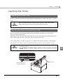
Clean and dry the printer case where the buzzer unit will be installed.
3
With 2 included pieces of the affixing tape combined, peel off the
backing paper on one side, and stick the tape in the center of the
attaching surface of the buzzer unit.
Affixing tape
56
Chapter 2 Setup
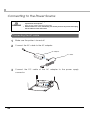
4
Connect the cable of the buzzer unit to the DK connector on the printer.
DK connector
5
Peel off the backing paper on the other side of the affixing tape, and
attach the buzzer unit to the printer case.
Printer case
2
57
Connecting the Cash Drawer
Do not connect both the optional external buzzer and the cash drawer to the printer at
the same time by using a branched connector.
When the optional external buzzer is enabled with the memory switch (see "Setting the
Memory Switches/Receipt Enhancement" on page 46), a cash drawer cannot be used.
Be sure to disable it when you use a cash drawer.
Two driver transistors cannot be energized simultaneously.
Leave intervals longer than 4 times the drawer driving pulse when sending it
continuously.
Required specifications of cash drawers
Specifications of drawers differ depending on makers or models. When you use a drawer other
than specified, make sure its specification meets the following conditions.
Otherwise, devices may be damaged.
• The load, such as a drawer kick-out solenoid, must be connected between pins 4 and 2 or pins
4 and 5 of the DK connector.
• When the drawer open/close signal is used, a switch must be provided between DK connector
pins 3 and 6.
• The resistance of the load, such as a drawer kick-out solenoid, must be 24
input current must be 1A or less.
or more or the
• Be sure to use the 24V power output on drawer-kick out connector pin 4 for driving the equipment.
58
Chapter 2 Setup
Drawer Connection Diagram
F.G
1 DK connector
With shielded
2
3
Drawer
kick-out
solenoid
+24V 4
Control
device
5
6
Printer side
Drawer open/
close switch
6 5 4 3 2 1
User side
[Drawer kick-out side]
2
Connecting the DK cable
WARNING
Use a shield cable for the DK cable.
Do not insert a telephone line into the DK connector.
Doing so may damage the telephone line or printer.
Connect the DK cable to the DK connector by pressing firmly until the connector clicks into
place.
59
60
Chapter 3 Application Development Information
Application Development Information
This chapter describes how to control the printer and gives information useful for printer
application development.
How to Control the Printer
Use a driver or ESC/POS commands to control the printer.
Selecting a Driver
Choose one of the drivers listed in "Printer Drivers" on page 68, depending on the application
operating environment. You cannot control a single printer with more than one driver.
For information about the driver operating environment, see the installation manual for each
driver.
When you newly develop an application
• Use APD if you want to print TrueType fonts or print many graphics.
• OPOS ADK is recommended for system extensibility. An OPOS driver is provided for various
peripherals and it is a POS industry standard now. It enables POS system efficiency, reduction
of development cost, and effective use of application assets.
You can use all functions, including ones not supported by OPOS ADK or APD, by using
ESC/POS commands through your driver. Use the DIRECT I/O function of OPOS ADK, the
control A command of APD, or Status API to send ESC/POS commands from each driver.
(See "ESC/POS command functions" on page 62.)
61
3
ESC/POS Commands
ESC/POS is the Epson original printer command system. With ESC/POS commands, you can
directly control all the TM printer functions, but detailed knowledge of printer specifications or
combination of commands is required, compared to using a driver.
The ESC/POS command functions are listed as follows. For detailed information about ESC/
POS commands, see the ESC/POS Quick Reference or the ESC/POS Command Reference.
You can view the ESC/POS Command Reference by accessing the URL described in the "How to
Get Drivers, Manuals, and the Utility" on page 71 with a user ID that has been registered as an
account.
ESC/POS command functions
Commands for printing
Print and line feed
Print and return to standard mode (in page mode)
Print and carriage return
Print data in page mode
Print and feed paper
Print and feed n lines
Commands for line spacing
Set line spacing
Select default line spacing
Commands for print character
Cancel print data in page mode
Set right-side character spacing
Select print mode(s)
Select/cancel user-defined character set
Define user-defined characters
Turn underline mode on/off
Cancel user-defined characters
Turn emphasized mode on/off
Turn double-strike mode on/off
62
Chapter 3 Application Development Information
Select character font
Select an international character set
Turn 90° clockwise rotation mode on/off
Select character code table
Turn upside-down print mode on/off
Select character size
Turn white/black reverse print mode on/off
Turn smoothing mode on/off
Commands for panel buttons
Enable/disable panel buttons
Commands for print positions
Horizontal tab
Set absolute print position
Set horizontal tab positions
Select print direction in page mode
3
Set print area in page mode
Set relative print position
Select justification
Set absolute vertical print position in page mode
Set left margin
Set print area width
Set relative vertical print position in page mode
Commands for bit image
Select bit-image mode
Transmit the NV graphics memory capacity
Print the graphics data in the print buffer
Transmit the remaining capacity of the NV graphics memory
Transmit the remaining capacity of the download graphics memory
Transmit the key code list for defined NV graphics
Delete all NV graphics data
63
Delete the specified NV graphics data
Define the NV graphics data (raster format)
Print the specified NV graphics data
Transmit the key code list for defined download graphics
Delete all download graphics data
Delete the specified download graphics data
Define the downloaded graphics data (raster format)
Print the specified download graphics data
Store the graphics data in the print buffer (raster format)
Define downloaded bit image
Print downloaded bit image
Define Windows BMP NV graphics data
Define Windows BMP download graphics data
Commands for status
Transmit real-time status
Enable/disable Automatic Status Back (ASB)
Transmit status
Commands for barcode
Select print position of HRI characters
Select font for HRI characters
Set barcode height
Print barcode
Set barcode width
Commands for two-dimensional codes
PDF417: Set the number of columns in the data region
PDF417: Set the number of rows
PDF417: Set the width of module
PDF417: Set the row height
PDF417: Set the error correction level
PDF417: Select the options
64
Chapter 3 Application Development Information
PDF417: Store the data in the symbol storage area
PDF417: Print the symbol data in the symbol storage area
PDF417: Transmit the size information of the symbol data in the symbol storage area
QR Code: Select the model
QR Code: Set the size of module
QR Code: Select the error correction level
QR Code: Store the data in the symbol storage area
QR Code: Print the symbol data in the symbol storage data area
QR Code: Transmit the size information of the symbol data in the symbol storage area
MaxiCode: Select the mode
MaxiCode: Store the data in the symbol storage area
MaxiCode: Print the symbol data in the symbol storage area
MaxiCode: Transmit the size information of the symbol data in the symbol storage area
Two-dimensional GS1 DataBar: Set the width of module
Two-dimensional GS1 DataBar: Set the maximum width of GS1 DataBar Expanded Stacked
3
Two-dimensional GS1 DataBar: Store the data in the symbol storage area
Two-dimensional GS1 DataBar: Print the symbol data in the symbol storage area
Two-dimensional GS1 DataBar: Transmit the size information of the symbol data in the symbol
storage area
Composite Symbology: Set the width of module
Composite Symbology: Set the maximum width of GS1 DataBar Expanded Stacked
Composite Symbology: Select font for HRI characters
Composite Symbology: Store the data in the symbol storage area
Composite Symbology: Print the symbol data in the symbol storage area
Composite Symbology: Transmit the size information of the symbol data in the symbol storage
area
Commands for mechanical control
Select cut mode and cut paper
Commands for customization
Write to NV user memory
Read from NV user memory
65
Change into the user setting mode
End the user setting mode session
Set values for the memory switch
Transmit the setting of the memory switch
Set the customized setting values
Transmit the customized setting values
Set conditions for serial interface communication
Transmit conditions for serial interface communication
Set conditions for USB interface communication
Transmit conditions for USB interface communication
Commands for macro function
Start/end macro definition
Execute macro
Commands for receipt enhancement
Cancel set values for top/bottom logo printing
Transmit set values for top/bottom logo printing
Set top logo printing
Set bottom logo printing
Make extended settings for top/bottom logo printing
Enable/disable top/bottom logo printing
Miscellaneous commands
Send real-time request to printer
Generate pulse in real-time
Execute power-off sequence
Control buzzer (optional external buzzer)
Clear buffer(s)
Sound buzzer (sound pattern specified) (optional external buzzer)
Select peripheral device
Initialize printer
Select page mode
66
Chapter 3 Application Development Information
Select standard mode
Generate pulse
Execute test print
Enable/disable real-time command
Specifies the process ID response
Select the print control mode
Select the print speed
Transmit printer ID
Set horizontal and vertical motion units
Initialize maintenance counter
Transmit maintenance counter
3
67
Software and Manuals
The following software and manuals are provided for application development.
Printer Drivers
Software
EPSON Advanced Printer Driver (APD):
APD Install Manual
In addition to ordinary Windows driver functions, this
driver has controls specific to POS, such as controls for
paper cut, a cash drawer, and customer display. The
Status API (Epson original DLL) that monitors printer
status and sends ESC/POS commands is also
attached to this driver.
APD TM/BA/EU Printer Manual
EPSON OPOS ADK:
OPOS Installation Manual
This OCX driver can control POS peripherals using OLE
technology*1. Because controlling POS peripherals
with original commands is not required on the
application side, efficient system development is
possible.
User’s Manual
APD Printer Specification
Status API Manual
Devmode API/PRINTERINFO Manual
Sample Program Guide
TM-T20II Software User’s Manual
Application Development Guide
UnifiedPOS Retail Peripheral Architecture*2
Sample Program Guide
EPSON OPOS ADK for .NET:
OPOS ADK for .NET Installation Guide
OPOS ADK for .NET allows you to develop
applications that are compatible with Microsoft POS
for .NET.
User's Reference (SetupPOS)
When developing applications, use a separate
development environment such as Microsoft Visual
Studio .NET.
UnifiedPOS Retail Peripheral Architecture*2
EPSON JavaPOS ADK (Windows/Linux):
JavaPOS ADK Installation Guide
JavaPOS is the standard specification which defines
an architecture and device interface (API) to access
various POS devices from a Java based system. Using
JavaPOS standard API allows control with Javabased applications of functions inherent to each
device. A flexible design with Java language and
JavaPOS enables many different types of computer
systems, such as stand alone or network
configuration, to use a same application. You can
use JavaPOS to build applications and drivers
independently of platforms. This allows flexible
configurations using thin clients to meet the system
requirements.
68
Manual
Application Development Guide
(POSPrinter TM-T20II)
Chapter 3 Application Development Information
Software
EPSON TM Virtual Port Driver:
Manual
TM Virtual Port Driver User’s Manual
This driver is a Serial-USB/Ethernet and Parallel-USB/
Ethernet conversion driver to make an EPSON TM/BA/
EU printer connected via USB/Ethernet accessible
from a POS application through virtual COM ports
and a virtual LPT port. Without making changes in the
POS application that controls devices connected
through serial or parallel interfaces, devices
connected via USB/Ethernet can be directly
controlled with ESC/POS commands.
TM-T20II Mac Printer Driver:
TM-T20II Mac Printer Driver User's Manual
Mac printer driver allows you to control the TM-T20II
using Common UNIX Printing System (CUPS) on Mac
OS X.
This is a full raster printer driver. It is able to print
images, text, and vector graphics etc., that an
application displays. With this driver many printer
controls are possible, such as paper cut timing
control, cash drawer control, printing speed control,
blank line skip, and upside-down printing. It also
provides API and dialogues for print setting, sample
applications, and logo setting utility.
Epson TM/BA Series Thermal Printer Driver:
This driver allows you to control the TM-T20II using
Common UNIX Printing System (CUPS) on GNU/Linux.
This is a full raster printer driver. It is able to print
images, text, and vector graphics etc., that an
application displays. With this driver many printer
control are possible, such as paper cut timing control,
cash drawer control, printing speed control, blank
line skip, and upside-down printing.
3
Epson TM/BA Series Thermal Printer Driver
Installation Manual
Epson TM/BA Series Thermal Printer Driver
Manual
TM-T20II Thermal Printer Driver Manual
*1: OLE technology developed by Microsoft divides software into part blocks. The OPOS driver
is presupposed to be used with a development environment such as Visual Basic, unlike
ordinary Windows drivers. It is not a driver to be used for printing from commercial
applications.
*2: This guide describes general information on how to control printers using the OPOS ADK (in
the chapter “POS Printer” and “Appendix-A”). It does not describe Epson’s specific functions.
69
Utilities
Software
Manual
TM-T20II Utility:
TM-T20II Software User’s Manual
Use for the following functions:
Checking current settings
Operation check
Storing logos
Coupon settings
Paper reduction settings
Automatic paper cut settings
Printing control settings
Font settings
Optional buzzer settings
Communication I/F settings
Backup/restore
TM-T20II Utility User’s Manual
EpsonNet Config:
EpsonNet Config Operations Guide
Use for IP address setting.
EpsonNet Simple Viewer:
EpsonNet Simple Viewer User’s Manual
Use for checking the status of EPSON printers
connected to a network and EPSON TM/BA printers
connected to computers on a network.
TM/BA/EU Printer Remote Configuration Tool:
This is a package of EpsonNet Simple Viewer and
TM-T20II Utility. First install this software in the
computer with the administrator's authority, and set
up the firewall. Next, install the printer driver in each
client computer and set up the firewall. Then you
can check the status of and configure the printer
connected to a client computer on the network
from the computer with the administrator's authority.
70
TM/BA/EU Printer Remote Configuration Tool
User’s Manual
Chapter 3 Application Development Information
How to Get Drivers, Manuals, and the Utility
Drivers, manuals, and the TM-T20II Utility can be installed by the TM-T20II installer in the
included TM-T20II Software & Documents Disc.
• For customers in North America, go to the following web site:
http://www.epsonexpert.com/
• For customers in other countries, go to the following web site:
http://download.epson-biz.com/?service=pos
3
71
Setting/Checking Modes
Besides the ordinary print mode, the printer has the following modes to set or check settings of
the printer.
• Self-test Mode
• NV Graphics Information Print Mode (page 74)
• Receipt Enhancement Information Print Mode (page 76)
• Software Setting Mode (page 78)
• Hexadecimal Dumping Mode (page 80)
Self-test Mode
In the self-test mode, the printer prints the current printer status and a rolling pattern test print
of resident characters.
The current status print includes the following information:
• Control ROM version
• Interface type
• Receive buffer size
• BUSY condition
• Resident fonts
• Print density
• Maintenance counter information (head running length, number of times of autocutting)
• Memory switch settings
72
Chapter 3 Application Development Information
Starting the self-test mode
Follow the steps below to run this mode.
1
2
Close the roll paper cover.
While pressing the Feed button, turn on the printer. (Keep pressing the
Feed button until the printer starts printing.)
The printer starts printing current status of the printer.
When the printer finishes printing the printer status, the following message is printed and
the Paper LED flashes. (The printer is now in the self-test wait mode.):
“Select Modes by pressing Feed button.
Continue SELF-TEST: Less than 1 second
Mode Selection:
3
1 second or more”
Press the Feed button to start the test print (less than 1 second).
The printer starts test printing. (A rolling pattern is printed using only the resident
character set.)
If you select “Mode Selection,” the printer goes to "NV Graphics Information Print Mode"
(page 74), "Receipt Enhancement Information Print Mode" (page 76), or "Software Setting
Mode" (page 78).
After the test printing has finished, the printer prints the following message, and then the
printer is initialized and returned to the normal mode.
“*** completed***”
73
3
NV Graphics Information Print Mode
You can confirm the following information by running the NV graphics information print mode:
• Capacity of the NV graphics
• Used capacity of the NV graphics
• Unused capacity of the NV graphics
• Number of NV graphics that are registered
• Key code, number of dots in X direction, number of dots in Y direction, number of colors to be
defined.
• NV graphics data
Starting the NV graphics information print mode
Follow the steps below to run this mode.
1
2
Close the roll paper cover.
While pressing the Feed button, turn on the printer. (Keep pressing the
Feed button until the printer starts printing.)
The printer starts printing current status of the printer.
When the printer finishes printing the printer status, the following message is printed and
the Paper LED flashes. (The printer is now in the self-test wait mode.):
“Select Modes by pressing Feed button.
Continue SELF-TEST: Less than 1 second
Mode Selection:
74
1 second or more”
Chapter 3 Application Development Information
3
Press the Feed button for 1 second or more to enter the Mode Selection.
The printer starts printing instructions.
Mode Selection
Modes
0 : Exit and Reboot Printer
1 : NV Graphics Information
2 : Receipt Enhancement Information
3 : Customize Value Settings
4 : or more: None
Select Modes by executing following
procedure.
step 1. Press the Feed button less
than 1 second as many times
as the selected mode number.
step 2. Press Feed button for 1
second or more.
4
5
Press the Feed button once, and then hold down the Feed button until
the printer starts printing the NV graphics information.
Turn off the printer or select "Exit and Reboot Printer" to exit this mode.
75
3
Receipt Enhancement Information Print Mode
You can confirm the following information by running the R/E information mode:
• Automatic top logo setting
• Automatic bottom logo setting
• Extended settings for automatic top/bottom logo
Starting the R/E information print mode
Follow the steps below to run this mode.
1
2
Close the roll paper cover.
While pressing the Feed button, turn on the printer. (Keep pressing the
Feed button until the printer starts printing.)
The printer starts printing current status of the printer.
When the printer finishes printing the printer status, the following message is printed and
the Paper LED flashes. (The printer is now in the self-test wait mode.):
“Select Modes by pressing Feed button.
Continue SELF-TEST: Less than 1 second
Mode Selection:
76
1 second or more”
Chapter 3 Application Development Information
3
Press the Feed button for 1 second or more to enter the Mode Selection.
The printer starts printing instructions.
Mode Selection
Modes
0 : Exit and Reboot Printer
1 : NV Graphics Information
2 : Receipt Enhancement Information
3 : Customize Value Settings
4 : or more: None
Select Modes by executing following
procedure.
step 1. Press the Feed button less
than 1 second as many times
as the selected mode number.
step 2. Press Feed button for 1
second or more.
4
5
Press the Feed button twice, and then hold down the Feed button until
the printer starts printing the R/E information.
Turn off the printer or select "Exit and Reboot Printer" to exit this mode.
77
3
Software Setting Mode
Starting the Software setting mode
Follow the steps below to run this mode.
1
2
Close the roll paper cover.
While pressing the Feed button, turn on the printer. (Keep pressing the
Feed button until the printer starts printing.)
The printer starts printing current status of the printer.
When the printer finishes printing the printer status, the following message is printed and
the Paper LED flashes. (The printer is now in the self-test wait mode.):
“Select Modes by pressing Feed button.
Continue SELF-TEST: Less than 1 second
Mode Selection:
3
1 second or more”
Press the Feed button for 1 second or more to enter the Mode Selection.
The printer starts printing instructions.
Mode Selection
Modes
0 : Exit and Reboot Printer
1 : NV Graphics Information
2 : Receipt Enhancement Information
3 : Customize Value Settings
4 : or more: None
Select Modes by executing following
procedure.
step 1. Press the Feed button less
than 1 second as many times
as the selected mode number.
step 2. Press Feed button for 1
second or more.
78
Chapter 3 Application Development Information
4
Press the Feed button three times, and then hold down the Feed button
until the printer starts printing the setting instructions.
Customize Value Settings
Modes
0 : Exit
1 : Print Current Settings
2 : Print Density
3 : Printing Speed
4 : Serial Interface Settings
5 : Auto Paper Feed&Cut at cover close
6 : Paper Width
8 : Default Character
9 : Embedded Font Replacement
10 : USB Interface Settings
11 : Buzzer Control
12 : Column Emulation
13 : Interface Settings
15 : Logo Emulation
16 : Automatic Paper Reduction
17 : Interface Selection
18 : Power Supply Unit Capacity
Select Modes by executing following
procedure.
step 1. Press the Feed button less
than 1 second as many times
as the selected mode number.
step 2. Press Feed button for 1
second or more.
5
6
3
Select the setting item by pressing the Feed button (no longer than 1
second) for the number of times indicated on the print.
Then hold down the Feed button until the printer starts printing the setting condition.
Select the setting condition by pressing the Feed button (no longer than
1 second) for the number of times indicated on the print.
Then hold down the Feed button until the printer starts printing the setting result.
When one setting has been completed, the printer stores the setting.
See "Setting Conditions for Software Setting Mode" on page 93 for the selectable items.
79
7
Turn off the printer or select "Exit" and "Exit and Reboot Printer" to exit this
mode.
To select the item number 0, hold down the Feed button until the printer starts printing.
If you pressed the button for the number of times that is not listed on the print, the
operation is invalid, and the same result is printed again.
Hexadecimal Dumping Mode
In the hexadecimal dumping mode, the printer prints the data transmitted from a host computer
in hexadecimal numbers and their corresponding characters. It enables you to check if data is
transmitted to the printer correctly.
Starting the hexadecimal dumping mode
Follow the steps below to run this mode.
If there is no character corresponding to print data, “.” is printed.
If print data is less than one line, press the Feed button to print the line.
1
Open the roll paper cover.
2
While pressing the Feed button, turn on the printer.
3
Close the roll paper cover.
The printer starts printing data received from then on in hexadecimal numbers and their
corresponding characters.
Turn off the printer or press the Feed button three times to return to the normal mode.
Printing example:
Hexadecimal Dump
To terminate hexadecimal dump,
press FEED button three times.
1B 21 00 1B 26 02 40 40 1B 69 . ! . . & . @ @ . i
1B 25 01 1B 63 34 00 1B 30 31 . % . . c 4 . . 0 1
41 42 43 44 45 46 47 48 49 4A A B C D E F G H I J
***
80
completed
***
Chapter 4 Handling
Handling
This chapter describes basic handling of the printer.
Installing and Replacing Roll Paper
CAUTION
Do not open the roll paper cover during printing or autocutting.
The printer may be damaged.
Do not touch the manual cutter with your hands when installing or replacing the
roll paper.
Otherwise, you may be injured because the manual cutter blade is sharp.
Use roll paper that meets the printer specification. For details about paper specification,
see "Paper Specifications" on page 25.
Paper must not be pasted to the roll paper core.
1
Open the roll paper cover by using the cover open lever.
4
Cover open lever
2
Remove the used roll paper core, if it is installed.
81
3
Install the roll paper in the correct direction.
4
Pull out some roll paper, and close the roll paper cover.
When the printer power is on, the roll paper is automatically cut. (initial setting)
2
1
82
Chapter 4 Handling
Removing Jammed Paper
Do not touch the thermal head. (See "Cleaning the Printer" on page 85.)
It can be very hot after printing.
CAUTION
When a paper jam occurs, never pull out the paper forcibly.
If a paper jam occurred, follow the steps below to recover.
1
Turn off the printer.
2
Open the roll paper cover by using the cover open lever.
Cover open lever
4
83
3
If the cover cannot be opened, move the stuck auto cutter blade with
the following method.
Remove the cutter cover by sliding toward the front.
Cutter cover
Indent
Turn the knob in the direction of the arrow until the triangle mark is appeared in the opening. (This returns the cutter blade to the standby position.)
Triangle
Knob
Attach the cutter cover.
84
4
Remove the jammed paper.
5
Close the roll paper cover and turn on the printer.
Chapter 4 Handling
Cleaning the Printer
Cleaning the Printer Case
Be sure to turn off the printer, and wipe the dirt off the printer case with a dry cloth or a damp
cloth.
Never clean the product with alcohol, benzine, thinner, or other such solvents.
Doing so may damage or break the parts made of plastic and rubber.
CAUTION
Cleaning the Thermal Head/Platen Roller
Epson recommends cleaning the thermal head periodically (generally every 3 months) to
maintain receipt print quality.
Depending on the roll paper used, paper dust may stick to the platen roller and the paper may
not be fed correctly. To remove the paper dust, clean the platen roller.
Turn off the printer, open the roll paper cover, and clean the thermal elements of the thermal
head/platen roller with a cotton swab moistened with an alcohol solvent (ethanol or IPA).
CAUTION
After printing, the thermal head can be very hot. Do not touch it and let it cool
before you clean it.
Do not damage the thermal head by touching it with your fingers or any hard
object.
Thermal element of
the thermal head
Platen roller
85
4
Preparing for Transport
Follow the steps below to transport the printer.
86
1
Turn off the printer.
2
Disconnect the AC cable from the socket.
3
Remove the roll paper.
4
Pack the printer upright.
Chapter 5 Replacement of the TM-T20
Replacement of the TM-T20
The TM-T20II is designed so that it can smoothly replace the TM-T20. This chapter describes
precautions for the replacement.
Additional Functions and Functional Improvements
Print Speed
The TM-T20II has increased its print speed up to a maximum of 200 mm/s.
Maximum print speed
TM-T20II
TM-T20
200 mm/s {7.87"/s}
150 mm/s {5.91"/s}
Note: When the printer prints text (built-in fonts) with the default print density level at 24 V and
25°C {77°F}.
Depending on print conditions such as print duty, print head temperature, and data
transmission speed, print speed is automatically adjusted.
5
87
88
Appendix
Appendix
Specifications of Interface and Connector
USB (Universal Serial Bus) Interface
USB interface connector
Has a USB upstream port connector (USB type-B connector)
USB transmission specifications
USB function
Overall specifications
According to USB 2.0 specifications
Transmission speed
USB Full-Speed (12 Mbps)
Transmission method
USB bulk transmission method
Power supply specifications
USB self power supply function
Current consumed by USB bus
2 mA
USB packet size (with full-speed
connection)
USB bulk OUT (TM)
64 bytes
USB bulk IN (TM)
64 bytes
USB device class
Select USB printer class or USB vendordefined class with the memory switch.
USB descriptor
USB vendor-defined class
USB printer class
Vendor ID
04b8h
04b8h
Product ID
0202h
0E15h
Manufacturer
EPSON
EPSON
Product
TM-T20II
TM-T20II
Serial number
Character string based on
the product serial number
Character string based on
the product serial number
String Descriptor
89
RS-232 Serial Interface
Interface board specifications (RS-232-compliant)
Item
Specifications
Data transfer method
Serial
Synchronization
Asynchronous
Handshake
Select one of the following with the memory switch:
DTR/DSR
Signal level
XON/XOFF
MARK
-3V to -15V logic “1”/OFF
SPACE
+3V to +15V logic “0”/ON
Transmission speed
Select one of the following with the memory switch:
2400/4800/9600/19200/38400/57600/115200 bps
[bps: bits per second]
Bit length
Select one of the following with the memory switch:
7 bit
Parity
Select one of the following with the memory switch:
None
Stop bit
8 bit
Even
Odd
1 or more bits
However, the stop bit for data transfer from the printer is fixed to 1 bit.
Connector
90
DSUB 25-pin (female) connector
Appendix
Functions of each connector pin
Pin no.
Signal name
Signal direction
Function
1
FG
—
Frame ground
2
TXD
Output
Transmission data
3
RXD
Input
Reception data
4
RTS
Output
Equivalent to DTR signal
6
DSR
Input
This signal indicates whether the host computer can
receive data.
SPACE indicates that the host computer can receive
data. MARK indicates that the host computer
cannot receive data.
When DTR/DSR control is selected, the printer
transmits data after confirming this signal (except if
transmitted using some ESC/POS commands).
When XON/XOFF control is selected, the printer does
not check this signal.
The printer is reset when the signal remains MARK for
a pulse width of 1 ms or more.
7
SG
—
Signal ground
20
DTR
Output
1) When DTR/DSR control is selected, this signal
indicates whether the printer is BUSY.
SPACE status
Indicates that the printer is ready to receive data.
MARK status
Indicates that the printer is BUSY. Set BUSY conditions
with the memory switch.
2) When XON/XOFF control is selected, the signal
indicates that the printer is properly connected and
ready to receive data from the host. The signal is
always SPACE, except in the following cases:
During the period from when power is turned on to
when the printer is ready to receive data.
During the self-test.
25
INT
Input
The printer is reset if the signal remains at SPACE for a
pulse width of 1 ms or more.
91
XON/XOFF
When XON/XOFF control is selected, the printer transmits the XON or XOFF signals as follows.
The transmission timing of XON/XOFF differs, depending on the setting of the memory switch.
Memory switch 1-3
Signal
XON
XOFF
Printer status
1 (ON)
0 (OFF)
1) When the printer goes online after turning on the power
Transmit
Transmit
2) When the receive buffer is released from the buffer full state
Transmit
Transmit
3) When the printer switches from offline to online
—
Transmit
4) When the printer recovers from an error using some ESC/POS
commands
—
Transmit
Transmit
Transmit
—
Transmit
5) When the receive buffer becomes full
6) When the printer switches from online to offline
Code
The hexadecimal numbers corresponding to the XON/XOFF codes are shown below.
• XON code: 11H
• XOFF code: 13H
When the printer goes from offline to online and the receive buffer is full, XON is not
transmitted.
When the printer goes from online to offline and the receive buffer is full, XOFF is not
transmitted.
Ethernet Interface
For information about the ethernet interface, see the UB-E03 Technical Reference Guide.
92
Appendix
Setting Conditions for Software Setting Mode
For information about setting the Software Setting Mode, see "Software Setting Mode" on page
78.
Setting Items
1st page
Selection of software settings
2nd page
The initial setting is underlined.
3rd page
1: Print Current Settings
-
2: Print Density
85%, 90%, 95%, 100%, 105%, 110%, 115%
1: Monochrome
3: Printing Speed
4: Serial
Interface
Settings
Level 1(Slow) to Level 13(Fast)
1: Baud Rate
2400bps, 4800bps, 9600bps, 19200bps,
38400bps, 57600bps, 115200bps
2: Parity
None, Odd, Even
3: Handshaking
DTR/DSR, XON/XOFF
4: Data Bits
7 bits, 8 bits
5: Data Receive Error
Print "?", Ignored
5: Auto Paper Feed&Cut at cover close
Enable, Disable
6: Paper Width
80mm, 58mm
8: Default
Character
1: Code Page
1: Western
Europe,
Southern Europe
Page0:PC437(USA,Standard Europe),
Page3:PC860(Portuguese),
Page11:PC851(Greek),
Page14:PC737(Greek),
Page15:ISO8859-7(Greek),
Page16:WPC1252, Page18:PC852(Latin2),
Page19:PC858, Page34:PC855(Cyrillic),
Page38:PC869(Greek),
Page39:ISO8859-2(Latin2),
Page40:ISO8859-15(Latin9),
Page45:WPC1250, Page47:WPC1253
2: Eastern
Europe,
Northern Europe
Page5:PC865(Nordic),
Page17:PC866(Cyrillic#2),
Page33:WPC775,
Page35:PC861(Icelandic),
Page42:PC1118(Lithuanian),
Page43:PC1119(Lithuanian),
Page44:PC1125(Ukrainian),
Page46:WPC1251, Page51:WPC1257
3: USA Canada
Page0:PC437(USA,Standard Europe),
Page4:PC863(Canadian-French)
93
Setting Items
1st page
8: Default
Character
(Continued from
the previous page)
2nd page
1: Code Page
3rd page
The initial setting is underlined.
4: Asia
Page1:Katakana, Page20:KU42,
Page21:TIS11(Thai), Page26:TIS18(Thai),
Page30:TCVN-3(Vietnamese),
Page31:TCVN-3(Vietnamese),
Page52:WPC1258,
Page53:KZ-1048(Kazakhstan)
5: Turkey, Arabia,
Israel
Page12:PC853(Turkish),
Page13:PC857(Turkish), Page32:PC720,
Page36:PC862(Hebrew),
Page37:PC864(Arabic),
Page41:PC1098(Farsi), Page48:WPC1254,
Page49:WPC1255, Page50:WPC1256
6: Others
Page2:PC850(Multilingual)
1: The Americas,
Europe
USA, France, Germany, Britain, Denmark I,
Sweden, Italy, Spain I, Norway, Denmark II,
Spain II, Latin America, Slovenia/Croatia
2: Asia, Arabia
Japan, Korea, China, Vietnam, Arabia
(Continued from
the previous page)
2: International
Character Set
9: Embedded
Font
Replacement
1: Font A Replacement
Font A(No Replacement), Font B
2: Font B Replacement
Font A, Font B(No Replacement)
10: USB Interface
Settings
1: Class
Vendor Class, Printer Class
2: USB Power Saving
Enabled, Disabled
11: Buzzer
Control
1: Option Buzzer
Enable, Disable
2: Buzzer Frequency(Error)
Continuous, 1 time, No sound
3: Sound Pattern(Autocut)
Pattern A, Pattern B, Pattern C, Pattern D,
Pattern E
4: Buzzer Frequency(Autocut)
1 time, No sound
5: Sound Pattern(Pulse 1)
Pattern A, Pattern B, Pattern C, Pattern D,
Pattern E
6: Buzzer Frequency(Pulse 1)
1 time, No sound
7: Sound Pattern(Pulse 2)
Pattern A, Pattern B, Pattern C, Pattern D,
Pattern E
8: Buzzer Frequency(Pulse 2)
1 time, No sound
12: Column Emulation
94
Selection of software settings
Off, 42 Column Mode
Appendix
Setting Items
1st page
13: Interface
Settings
2nd page
3rd page
The initial setting is underlined.
1: Receive Buffer Capacity
4KB, 45 bytes
2: BUSY Condition
Receive Buffer Full or Offline, Receive
Buffer Full
3: Auto Line Feed
Always disabled, Always enabled
4: State to cancel buffer BUSY
Not BUSY = 256 bytes, Not BUSY = 138
bytes
5: Output Paper-end Signals
Paper End Sensor Enabled, Disabled
6: Error Signal
Enabled, Disabled
15: Logo Emulation
16: Automatic
Paper
Reduction
Selection of software settings
Off, 180 Dpi Logo Mode
1: Upper Margin
Enable, Disable
2: Lower Margin
Enable, Disable
3: Blank Line Spacing
25%, 50%, 75%, Not Reduce
4: Blank Space
25%, 50%, 75%, Not Reduce
5: Barcode Height
25%, 50%, 75%, Not Reduce
17: Interface Selection
UIB, Built-in USB, Auto
18: Power Supply Unit Capacity
Level 1(Low) to Level 3(High)
95
Character Code Tables
The character code tables show only character configurations. They do not show the
actual print pattern.
“SP” in the table shows a space.
Common to All Pages
When International character set (See "International Character Sets" on page 140.) is USA:
96
Appendix
Page 0 [PC437: USA, Standard Europe]
97
Page 1 (Katakana)
98
Appendix
Page 2 (PC850: Multilingual)
99
Page 3 (PC860: Portuguese)
100
Appendix
Page 4 (PC863: Canadian-French)
101
Page 5 (PC865: Nordic)
102
Appendix
Page 11 (PC851: Greek)
103
Page 12 (PC853: Turkish)
104
Appendix
Page 13 (PC857: Turkish)
105
Page 14 (PC737: Greek)
106
Appendix
Page 15 (ISO8859-7: Greek)
107
Page 16 (WPC1252)
108
Appendix
Page 17 (PC866: Cyrillic #2)
109
Page 18 (PC852: Latin2)
110
Appendix
Page 19 (PC858: Euro)
111
Page 20 (KU42: Thai)
112
Appendix
Page 21 (TIS11: Thai)
113
Page 26 (TIS18: Thai)
114
Appendix
Page 30 (TCVN-3: Vietnamese)
115
Page 31 (TCVN-3: Vietnamese)
116
Appendix
Page 32 (PC720: Arabic)
117
Page 33 (WPC775: Baltic Rim)
118
Appendix
Page 34 (PC855: Cyrillic)
119
Page 35 (PC861: Icelandic)
120
Appendix
Page 36 (PC862: Hebrew)
121
Page 37 (PC864: Arabic)
122
Appendix
Page 38 (PC869: Greek)
123
Page 39 (ISO8859-2: Latin2)
124
Appendix
Page 40 (ISO8859-15: Latin9)
125
Page 41 (PC1098: Farsi)
126
Appendix
Page 42 (PC1118: Lithuanian)
127
Page 43 (PC1119: Lithuanian)
128
Appendix
Page 44 (PC1125: Ukrainian)
129
Page 45 (WPC1250: Latin 2)
130
Appendix
Page 46 (WPC1251: Cyrillic)
131
Page 47 (WPC1253: Greek)
132
Appendix
Page 48 (WPC1254: Turkish)
133
Page 49 (WPC1255: Hebrew)
134
Appendix
Page 50 (WPC1256: Arabic)
135
Page 51 (WPC1257: Baltic Rim)
136
Appendix
Page 52 (WPC1258: Vietnamese)
137
Page 53 (KZ1048: Kazakhstan)
138
Appendix
Page 255 (User-Defined Page)
139
International Character Sets
Country
ASCII code (Hex)
23
24
25
2A
40
5B
5C
5D
5E
60
7B
7C
7D
7E
]
^
`
{
|
}
~
USA
France
#
$
%
*
@
[
#
$
%
*
à
°
ç
§
^
`
é
ù
è
¨
Germany
#
$
%
*
§
Ä
Ö
Ü
^
`
ä
ö
ü
β
U.K.
£
$
%
*
@
[
]
^
`
{
|
}
~
Denmark I
#
$
%
*
@
Æ
Ø
Å
^
`
æ
ø
å
~
Sweden
#
¤
%
*
É
Ä
Ö
Å
Ü
é
ä
ö
å
ü
Italy
#
$
%
*
@
°
é
^
ù
à
ò
è
ì
Spain I
Pt
$
%
*
@
¡
Ñ
¿
^
`
¨
ñ
}
~
Japan
#
$
%
*
@
[
¥
]
^
`
{
|
}
~
Norway
#
¤
%
*
É
Æ
Ø
Å
Ü
é
æ
ø
å
ü
Denmark II
#
$
%
*
É
Æ
Ø
Å
Ü
é
æ
ø
å
ü
Spain II
#
$
%
*
á
¡
Ñ
¿
é
`
í
ñ
ó
ú
Latin America
Korea
#
$
%
*
á
¡
Ñ
¿
é
ü
í
ñ
ó
ú
#
$
%
*
@
[
W
]
^
`
{
|
}
~
Slovenia/Croatia
#
$
%
*
Ž
Š
Đ
Ć
Č
ž
š
đ
ć
č
China
Vietnum
#
Ұ
%
*
@
[
]
^
`
{
|
}
~
₫
$
%
*
@
[
]
^
`
{
|
}
~
Arabia
#
$
%
*
@
[
]
^
`
{
|
}
~
140