1
CONFIDENTIAL
SERVICE MANUAL
Impact Receipt Printer
BTP-M280
Shandong New Beiyang Information Technology Co., Ltd.
Confidential
BTP-M280 Service Manual
Revision Sheet
Date
Version No.
Description
Distributor
2007-05-16
V1.0
Release
Mr. zheng lei
Mr. zhao zhenxing
Mr. Yao Xingmao
Mr. Yu zhuanlong
2008-2-20
V1.01
Adjust the format of 1.2
Mr. Yu zhuanlong
-1-
Confidential
BTP-M280 Service Manual
Declaration
Information in this document is subject to change without notice. SHANDONG NEW BEIYANG
INFORMATION TECHNOLOGY CO., LTD. (hereinafter referred to as “SNBC”) reserves the right to
improve product as new technology, components, software, and firmware become available. If users need
further data about this products or have any doubt about safety issues that might arise from using it, please
feel free to contact SNBC or your local agents.
No part of this document may be reproduced or transmitted in any form or by any means, electronic or
mechanical, for any purpose without the express written permission of SNBC.
Copyright
Copyright © 2007 by SNBC
Printed in China
Version 1.01
Trademark
SNBC registered trademarks:
Warning and Caution
Warning: Items shall be strictly followed to avoid damages to body and equipment.
Caution: Items with important information and prompts for operating the printer.
The quality control system of SNBC has been approved of the following certification.
(DNV)ISO9001:2000
The environmental control system of SNBC has been approved of the following certification.
(DNV)ISO14001:2004
-2-
Confidential
BTP-M280 Service Manual
Notes
1)
Use this manual to troubleshoot printer faults.
2)
Do not plug or pull out the signal cable, change print head or do maintenance to the printer when the
printer and the computer are powered on.
3)
Please take anti-static application when you maintain print head and other electronics component.
4)
After turning off the printer, you should wait for at least 20 seconds if you want to turn on the printer
again.
5)
Do not print without paper and ribbon; otherwise you may damage the print head iron mat and print
head.
-3-
Confidential
BTP-M280 Service Manual
Contents
1 FEATURES AND SPECIFICATIONS ........................................................................................................1
1.1 FEATURES ............................................................................................................................................1
1.2 TECHNICAL SPECIFICATIONS..................................................................................................................2
2 PRINTER OVERVIEW ..............................................................................................................................3
2.1 MAIN CONTROL BOARD UNIT BLOCK DIAGRAM .......................................................................................3
3 MAIN CONTROL BOARD DESCRIPTION ...............................................................................................5
3.1 USB INTERFACE ...................................................................................................................................5
3.1.1 Parameter ...................................................................................................................................5
3.1.2 Interface signal............................................................................................................................5
3.1.3 USB interface connection............................................................................................................5
3.2 SERIAL INTERFACE ...............................................................................................................................5
3.2.1 Parameter ...................................................................................................................................5
3.2.2 Interface connection and signal function .....................................................................................6
3.2.3 Serial connection.........................................................................................................................6
3.3 PARALLEL INTERFACE ...........................................................................................................................6
3.3.1 Parameter ...................................................................................................................................6
3.3.2 Time Sequence of the Parallel Interface Module.........................................................................6
3.3.3 Pin assignment............................................................................................................................7
3.3.4 Parameter ...................................................................................................................................8
3.3.5 Effect of printer’s status on parallel interface...............................................................................8
3.4 ETHERNET INTERFACE ..........................................................................................................................8
3.4.1 Interface character ......................................................................................................................8
3.4.2 Protocol supported ......................................................................................................................9
3.4.3 Electrical character......................................................................................................................9
3.4.4 Frame type ..................................................................................................................................9
3.4.5 Pin assignment............................................................................................................................9
3.5 WLAN INTERFACE................................................................................................................................9
3.5.1 Interface character ......................................................................................................................9
-4-
Confidential
BTP-M280 Service Manual
3.5.2 Protocol supported ....................................................................................................................10
3.5.3 Electrical character....................................................................................................................10
4 DISASSEMBLY AND ASSEMBLY..........................................................................................................11
4.1 MAINTENANCE TOOLS .........................................................................................................................11
4.2 DISASSEMBLE THE PRINTER ................................................................................................................12
4.2.1 Disassemble the Cover of Printer..............................................................................................12
4.2.2 Disassemble the Main Control Board Cover .............................................................................14
4.2.3 Disassemble the Stationary Blade Cutter Module .....................................................................15
4.2.4 Disassemble the Platen Roller Module (Without Rewinder) ......................................................16
4.2.5 Disassemble the Paper Cabinet Module ...................................................................................18
4.2.6 Disassemble the Print Module...................................................................................................22
5 PRINTER MAINTENANCE .....................................................................................................................26
5.1 MAIN PART REPLACING ........................................................................................................................26
5.1.1
Print head replacing................................................................................................................26
5.1.2
Cutter replacing ......................................................................................................................27
5.1.3
Main control board replacing ..................................................................................................28
5.1.4
Paper feed motor replacing ....................................................................................................29
5.1.5
CR motor replacing.................................................................................................................29
5.1.6
Upper mark sensor replacing..................................................................................................30
5.1.7
Lower mark sensor replacing..................................................................................................31
5.1.8
HP sensor replacing ...............................................................................................................32
5.1.9
Paper sensor replacing...........................................................................................................32
5.2 PRINTER ADJUSTMENT ........................................................................................................................33
5.2.1 Print distance adjustment ..........................................................................................................33
5.2.2 Tight denti-form belt of carriage ................................................................................................33
6 ERROR TYPES AND PROCESSING .....................................................................................................34
7 TROUBLESHOOTING............................................................................................................................35
7.1 PRINT EFFECT ABNORMAL ...................................................................................................................35
7.2 PAPER DETECTION ABNORMAL .............................................................................................................35
-5-
Confidential
BTP-M280 Service Manual
7.3 PRINTING WITH NOISE .........................................................................................................................35
7.4 RIBBON ACTION ABNORMAL .................................................................................................................36
7.5 CUTTER ACTION ABNORMAL .................................................................................................................36
7.6 PRINTER DOESN’T WORK .....................................................................................................................37
7.7 PROBLEM DURING THE PRINTING PROCESS ..........................................................................................37
APPENDIX .................................................................................................................................................38
APPENDIX 1 HEXADECIMAL DUMP MODE ...................................................................................................38
APPENDIX 2 COMMAND LIST ......................................................................................................................39
APPENDIX 3 EEPROM SETTING TABLE ......................................................................................................41
APPENDIX 4 SPARE PART LIST ...................................................................................................................42
APPENDIX 5 EXPLODED DRAWING OF THE PRINTER .....................................................................................45
APPENDIX 6 PART LIST ..............................................................................................................................48
APPENDIX 7 OUTLINE DRAWING .................................................................................................................51
APPENDIX 8 MAIN BOARD LAYOUT .............................................................................................................52
APPENDIX 9 LUBRICATION .........................................................................................................................53
-6-
Confidential
BTP-M280 Service Manual
1 Features and Specifications
1.1 Features
The BTP-M280 is a 9 pin serial dot matrix receipt impact printer. Features include such as good print
quality, high speed printing and stable performance. It is widely used for receipt applications such for POS,
Kitchen and Finance terminal.
The BTP-M280 can be connected to host computers via a Serial interface, Parallel interface, USB interface,
Ethernet interface, WLAN interface. USB is the standard interface and other interfaces are optional.
The BTP-M280 offers drivers and applications under WINDOWS 98/NT4.0 /2000/2003/XP/Vista.
-1-
Confidential
BTP-M280 Service Manual
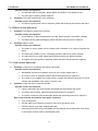
1.2 Technical Specifications
Item
Specification
Print mode
9-pin serial impact dot matrix
Print speed
Max. 4.7LPS (400 dots/line)
Print width
Max. 400(half dots)/200(full dots)
Paper type
Paper
Character
Data
buffer
Single layer
Continuous paper or marked paper
Paper width: 80±0.5mm, 76±0.5mm, 69.5±0.5mm, 57.5±0.5mm;
Paper thickness: 0.06—0.085mm
Multi-layer paper
Paper width: 80±0.5mm, 76±0.5mm, 69.5±0.5mm, 57.5±0.5mm;
(1 original+1 copies)
Paper thickness: 0.05—0.08mm, total thickness≤0.14 mm
Character type
Font A: 9×9 Font B: 7×9
Chinese: 16×16
80/76mm
69.5mm
57.5mm
Font A
33 CPL
30 CPL
25 CPL
Font B
40 CPL
36 CPL
30 CPL
Chinese
22 CPL
20 CPL
16 CPL
Characters/line (Default)
Character size (Default)
Font A: 1.6×3.1mm
Font B: 1.2×3.1mm Chinese: 2.7×2.9mm
Characters/inch (Default)
Font A: 13.3CPI
Font B: 16CPI
Receive buffer
8KB
NV bit image data area
128KB
User NV memory
8KB
Ribbon specification
Ribbon lifetime
Chinese: 8.9CPI
ERC-38 ribbon cartridge
ERC-38(P)
4,000,000 characters
ERC-38(B)
3,000,000 characters
Black: 1,500,000 characters
ERC-38(B/R)
Red: 750,000 characters
Communication interface
USB (Fixed) + IEEE1284/RS-232/Ethernet / Wi-Fi interface (optional)
Cash drawer connector
1~2 cash drawers
Power supply
DC 24V±5% average current 1.5 A
Reliability
Printing Mechanism lifetime
10,000,000 lines
Print head lifetime
150,000,000 characters
Cutter
1,500,000 times(partial cut, paper thickness:0.07mm)
1,000,000 times(full cut , paper thickness:0.07mm)
Operating temperature and humidity
5~45℃,20~90%RH (40℃)
Storage temperature and humidity
-40~60℃,20%~93%RH (40℃)
Dimensions
160mm(W)×245mm(D)×145mm(H)
Weight
2.9kg
-2-
Confidential
BTP-M280 Service Manual
2 Printer Overview
The BTP-M280 printer consisits of the following parts:
Pinter mechanism part, NDLF main control board, extended interface board.
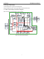
2.1 Main Control Board Unit Block Diagram
Carriage motor
drive chip
Communication interface
connector
1.8V
Motor drive signal
Paper feed motor
drive chip
5V
Print head drive signal
Main control board unit block diagram is shown as below:
FLASH
3.3V
Main Control Board Unit Block Diagram
-3-
Confidential
BTP-M280 Service Manual
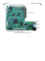
Position of all the sockets in the main control board
-4-
Confidential
BTP-M280 Service Manual
3 Main Control Board Description
BTP-M280 can be connected to another device with USB, serial, parallel, Ethernet or WIFI interface. The
USB interface is fixed and other is optional.
3.1 USB interface
3.1.1 Parameter
¾
Data transfer:Supports USB1.1 Protocol
¾
Socket:
USB A type standard socket
3.1.2 Interface signal
Pin
Signal
Function
1
VBUS
+5V
2
DATA-
Data-
3
DATA+
Data+
4
GND
Ground
3.1.3 USB interface connection
Host
Printer
VBUS..................................…VBUS
DATA- ................................…DATADATA+................................... DATA+
GND .......................................GND
3.2 Serial interface
3.2.1 Parameter
¾
Data transmission:
Asynchronous serial communicate
¾
Handshaking:
DTR/DSR or XON/XOFF
¾
Voltage:
MARK = -3 to -15V: Logic "1"/ OFF
¾
SPACE = +3 to +15V:Logic "0"/ ON
¾
Baud rate:
¾
[bps: bits per second]
¾
Data bit:
7 bit or 8 bit
¾
Parity bits:
No
¾
Stop bit:
1 bit or 2 bit
¾
Socket:
D-SUB 25PIN hole socket
1200, 2400, 4800, 9600, 19200, 38400, 57600 bps
Notice:
Handshaking, baud rate, data bit and stop bit can be set by EEPROM and feed button.
-5-
Confidential
BTP-M280 Service Manual
3.2.2 Interface connection and signal function
Signal and function:
Pin
Signal Name
Signal Direction
Function
1
FG
—
Frame ground
2
TXD
OUTPUT
Data output
3
RXD
INPUT
Data input
4
RTS
OUTPUT
Ask for sending
6
DSR
INPUT
Host ready
7
SG
—
Signal ready
20
DTR
OUTPUT
Data terminal ready
3.2.3 Serial connection
Host
Printer
TXD---------------RXD
RXD---------------TXD
DSR---------------DTR
CTS---------------RTS
RTS---------------CTS
DTR---------------DSR
FG -----------------FG
SG -----------------SG
3.3 Parallel interface
Parallel interface works under IEEE1284 compatible mode and bi-direction mode.
3.3.1 Parameter
¾
Data transmission:
8 bit parallel
¾
Synchronized mode:
Externally supplied nStrobe signals
¾
Handshaking mode:
Busy Signal
¾
Handshaking pressure:
TTL compatible
¾
Connector:
IEEE 1284-B(CENTRONICS) socket
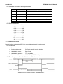
3.3.2 Time Sequence of the Parallel Interface Module
Time Sequence of
Parallel Interface(Compatible mode)
-6-
Confidential
BTP-M280 Service Manual
Signal
Min.
Max.
tSetup
750
-
tReady
0
-
tStb
750
-
tBusy
0
500
tHold
750
-
Time Request of Parallel Interface
3.3.3 Pin assignment
Pin
Signal source
Signal definition
Pin
1
H
nStrobe
19
Signal Ground
2
H
Data 0 (Least Significant Bit)
20
Signal Ground
3
H
Data 1
21
Signal Ground
4
H
Data 2
22
Signal Ground
5
H
Data 3
23
Signal Ground
6
H
Data 4
24
Signal Ground
7
H
Data 5
25
Signal Ground
8
H
Data 6
26
Signal Ground
9
H
Data 7 (Most Significant Bit)
27
Signal Ground
10
P
Ack
28
Signal Ground
11
P
Busy
29
Signal Ground
12
P
PError
30
Signal Ground
13
P
Select
31
H
nInit
14
H
nAutoLF
32
P
nFault
15
Not defined
33
Signal Ground
16
Logic Gnd
34
Not defined
17
Chassis Gnd
35
Not defined
Peripheral Logic High
36
18
P
Signal source
H
Signal definition
nSelectIn
Parallel Interface Pin Assignment
Notice:
H stands for host end, P stands for printer end.
Parallel interface signal adopting TTL pressure. Please make sure that both ascending and
descending time of the host end are less than 0.5μs when using the printer to print.
When data transmitting, the host end should not neglect the Busy signal, otherwise the
printing data will be lost.
The parallel interface signal cable should be as short as possible.
-7-
Confidential
BTP-M280 Service Manual
3.3.4 Parameter
3.3.5 Effect of printer’s status on parallel interface
Status
/nFault
PE
Normal status
High
Low
Paper end
Low
High
Rear cover open
Low
Low
Cutter error
Low
Low
Input voltage abnormal
Low
Low
Print head overheated
Low
Low
HP error
Low
Low
Notice:
When the above error occurs, user can inquire the printer’s status from the Pin of parallel.
3.4 Ethernet interface
3.4.1 Interface character
¾
Support
10BASE-T communicate
¾
Ethernet II frame type compatible
¾
LED indicates the net connection status and data transmission status
¾
Support
¾
Support auto status back
9100 port printing
-8-
Confidential
BTP-M280 Service Manual
¾
Support parameter configuration
¾
Support firmware update online
¾
Support printer status inquire and interface module maintenance based in HTTP mode
3.4.2 Protocol supported
¾
IP
¾
ARP
¾
ICMP
¾
TCP
¾
UDP
¾
DHCP
¾
TFTP
¾
HTTP
3.4.3 Electrical character
Output signal:
¾
Available differential mode voltage is bigger than 450Mv and peak voltage is no more than
13V.
¾
Peak voltage of common mode voltage is no more than 2.5V.
Input signal:
The signal is effective only when the differential mode voltage is bigger than 160mv.
3.4.4 Frame type
Ethernet II frame type compatible.
3.4.5 Pin assignment
The interface use 10BASE-T standard which comply to IEEE802.3.
Pin
Signal Name
Description
1
TX+
Data sending +
2
TX-
Data sending-
3
RX+
Data receiving+
4
NC
Reserved
5
NC
Reserved
6
RX-
Data receiving-
7
NC
Reserved
8
NC
Reserved
3.5 WLAN Interface
3.5.1 Interface character
¾
Support 802.11b/g protocol
¾
Support 9100 port printing and LPR printing
¾
Support auto status back
¾
Easy configuration
¾
Firmware update online
¾
Support HTTP function
-9-
Confidential
BTP-M280 Service Manual
3.5.2 Protocol supported
¾
IP
¾
ARP
¾
ICMP
¾
TCP
¾
UDP
¾
DHCP
¾
TFTP
¾
HTTP
3.5.3 Electrical character
Comply to 802.11b/g protocol.
- 10 -
Confidential
BTP-M280 Service Manual
4 Disassembly and Assembly
Cautions:
1)
Do not disassemble, assemble or adjust the printer if it works properly. Do not loosen any
screw unless necessary.
2)
When disassembling and assembling, avoid damaging all wires and cables. Do not place them
in a narrow space or improper position.
3)
When handling the print head or electronic component, make sure to take some measures to
protect it from electrostatic charge.
4)
During maintenance, be careful not to leave parts or screws loose inside the printer.
5)
During maintenance, be careful not to damage the print head surface and the HP iron mat.
4.1 Maintenance Tools
Maintenance Tools:
¾
Screw Driver (Cross-shaped type)
¾
Sharp-nose pliers
¾
Wire clamp pliers
Assistant materials:
¾
Lubricant
¾
Alcohol
¾
Absorbent cotton
- 11 -
Confidential
BTP-M280 Service Manual
4.2 Disassemble the Printer
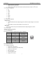
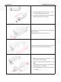
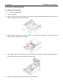
4.2.1 Disassemble the Cover of Printer
Instructions
Pictures
Top view of printer.
1)
Unscrew the two screws (M3x7) as shown with the
2)
Push the lock frame of lower cover with a moderate
screw driver;
force as the arrow shown in the figure and take it
off.
Note:
Please use a moderate force to avoid damage to the
lower cover when disassembling the lock frame.
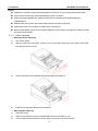
1)
Unscrew the two screws (2.9x8) as shown with the
screw driver;
2)
Push the lock frame of upper cover with a
moderate force as shown and take it off.
Note:
Please use a moderate force to avoid damage to the
upper cover when disassembling the upper cover.
- 12 -
Confidential
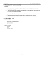
BTP-M280 Service Manual
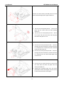
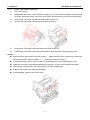
Unscrew the four screws (Four ST2.9x6) as shown with
the screw driver and take the front cover off.
Note:
Please use a moderate force to avoid damage to the font
cover when disassembling the front cover.
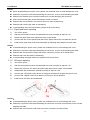
1)
Unscrew the two screws (M3x7) as shown with the
screw driver;
2)
Unplug the connection wire of Feed button and
that of main control board;
3)
Push the lock frame of middle cover with a
moderate force as shown and take it off;
4)
Take the middle cover holder off with a moderate
force.
Note:
Please use a moderate force to avoid damage to
the middle cover when disassembling the lock
switch;
Please do not pull the connection wire to avoid
damage to the wire when pluging and unplugging
the connection wire.
Unscrew the two screws (ST2.9x6) as shown with the
screw driver and take the Feed button board off.
- 13 -
Confidential
BTP-M280 Service Manual
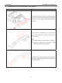
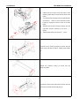
4.2.2 Disassemble the Main Control Board Cover
Instructions
Pictures
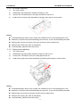
Unscrew two screws (M2.5x5) as shown and take the
interface module off.
Note:
Please use a moderate force to avoid bending the
interface
connector
pins
when
connecting
or
disconnecting the interface board.
1)
Unplug all the wires in the main control board with
a moderate force;
2)
Unscrew the four screws (M3 x 5) with the screw
driver and take the board off.
Note:
Please keep the main control board safely to avoid
scratching and short circuit.
Please do not pull the connection wire to avoid
damaging the wire when pluging and unplugging
the connection wire.
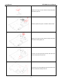
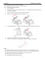
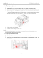
1)
Unscrew the two screws (M2x8) as shown item ①
of the figure with the screw driver and take the
micro switch off;
2)
Unscrew the two sink screws (M3x5) as shown
item ② of the figure with the screw driver and take
the guide plate off;
3)
Take the power switch off as the arrow shown in
the figure.
Unscrew the three screws (M3x5) as shown with the
screw driver and take the interface plate off as the arrow
shown in the figure.
- 14 -
Confidential
BTP-M280 Service Manual
4.2.3 Disassemble the Stationary Blade Cutter Module
Instructions
Pictures
Offload one E-ring from one side of the stationary blade
shaft with the sharp-nose pliers and pull the shaft as the
arrow shown in the fugure, take the stationary blade
module off.
Unscrew the two screws (M3x5) as shown with the
screw driver, separate the cutter holder and the
stationary blade.
Note:
Handle the stationary blade carefully to avoid injury.
Handle the stationary blade carefully to avoid
damaging the blade with hard material.
Unscrew the two screws (ST2.9x6) as shown with the
screw driver, separate right holder and the left holder of
the stationary blade.
- 15 -
Confidential
BTP-M280 Service Manual
4.2.4 Disassemble the Platen Roller Module (Without Rewinder)
Instructions
Pictures
1)
Cut off the tie wire of the cutter wire with wire clamp
pliers;
2)
Offload the E-ring in the side of the back shaft and
the E-ring in the middle with sharp-nose pliers, pull
the back shaft as the arrow shown in the figure,
take the platen roller module off (without rewinder).
1)
Unscrew the two screws (ST2.9x6) as shown with
the screw driver.
2)
Move the moving blade as the arrow shown in the
figure (Move forward and then move upward),
separate the moving blade module.
Unscrew the two screws (M3x5) as shown with the screw
driver, separate the moving blade and moving blade
fixed plate.
1)
Unscrew the four screws (ST2.9x6) as shown item
① with the screw driver;
2)
Separate the platen roller module as the arrow
shown in the figure;
3)
Unscrew one screw (ST2.9x6) as shown item ②
with the screw driver and take the micro switch
press plate off.
- 16 -
Confidential
BTP-M280 Service Manual
1)
Offload the three E-rings as shown item ① and ②
in the figure with the sharp-nose pliers;
2)
Pull the latch shaft as the arrow shown in the figure,
separate the latch and cover spanner.
1) Offload one E-ring as shown in the figure with the
sharp-nose pliers;
2) Separate the transition gear and gear 31-17.
Unscrew the three screws (ST2.6x6) as shown with the
screw driver and take the upper channel plate off.
1)
Offload the three E-rings as shown item ① in the
figure with the sharp-nose pliers;
2)
Take one bush off as the arrow shown item ② in the
figure;
3)
Take one platen roller gear and one bush off as the
arrow shown item ③ in the figure;
4)
Take one platen roller off as the arrow shown item
④ in the figure.
- 17 -
Confidential
BTP-M280 Service Manual
Unscrew the four screws (ST2.9x6) as shown with the
screw driver and take the print padding plate off.
When equipped the black mark sensor, unscrew the two
screws (ST2.2x4) as shown with the screw driver,
separate the black mark sensor and sensor dustproof
cover off.
4.2.5 Disassemble the Paper Cabinet Module
Instructions
Pictures
1)
Cut off the tie wire of all wires with wire clamp
pliers;
2)
Unscrew the four screws (ST2.9x6) as shown with
the screw driver and take the paper cabinet module
off from the main control board box.
Unscrew the two screws (ST2.9x6) as shown with the
screw driver and take the floatable wheel plate module
off.
- 18 -
Confidential
BTP-M280 Service Manual
1)
Offload the three E-rings as shown with the
sharp-nose pliers, separate the floatable wheel
shaft and floatable wheel;
2)
Unscrew the two screws (ST2.6x6) with the screw
driver and take the carriage spring plate off.
Unscrew the two screws (ST2.6x6) with the screw driver
and take the paper force spring plate off.
Unscrew the two screws (ST2.9x6) with the screw driver
and take the vertical paper cabinet off.
1)
Unscrew the two screws (ST2.6x6) as item ①
shown in the figure with the screw driver, separate
the paper end sensor and paper end sensor press
plate.
2)
When euipped the black mark sensor, unscrew the
two screws (ST2.2x4) as item ② shown in the
figure with the screw driver, separate the black
mark sensor and sensor dustproof cover.
- 19 -
Confidential
BTP-M280 Service Manual
Unscrew the three screws (ST2.9x6) with the screw
driver and take the right plate of paper cabinet off.
1)
Unscrew one screw (M3x6) as item ① shown in the
figure with the screw driver and take damping
washer off;
2)
Unscrew the two screws (M3x8) as item ② shown
in the figure with the screw driver, take the paper
feed motor and gear 31-17 off.
1)
Unscrew one screw (ST2.6x6) as item ① shown in
the figure with the screw driver, pull the lock frame
in a moderate force outwards and take horizontal
paper near end sensor off;
2)
Unscrew one screw (ST2.6x6) as item ② shown in
the figure with the screw driver, pull the lock frame
in a moderate force and take vertical paper near
end sensor off.
1)
Unscrew the two screws (ST2.6x4) as shown with
the screw driver and take the paper near end
sensor press plate off;
2)
Separate the horizontal paper near end sensor
plate holder and the vertical paper near end sensor
hoder as the arrow shown in the figure.
- 20 -
Confidential
BTP-M280 Service Manual
1)
Take the paper guide upwards in a moderate force
off as the arrows shown in the figure;
2)
Take the paper near end sensor adjustment
spanner off as the arrows shown in the figure.
Take the paper roller platen shaft off as the arrow shown
in the figure.
Unscrew the three screws (ST2.9x6) as shown with the
screw driver and take the right plate of paper cabinet off.
Unscrew the two screws (ST1.7x10) as shown with the
screw driver and take the micro switch off.
- 21 -
Confidential
BTP-M280 Service Manual
4.2.6 Disassemble the Print Module
Instructions
Pictures
Unscrew the four screws (ST2.9x6) as shown with the
screw driver and take the print module off.
1)
Offload the extension spring as shown with the
sharp-nose pliers;
2)
Offload one E-ring as shown with the sharp-nose
pliers;
3)
First move the ribbon support plate 4mm to the left
side in the horizontal direction as the arrow shown,
then lift up the ribbon support plate so as to take the
ribbon support plate off.
Unscrew the two screws (ST2.6x10) as shown with the
screw driver, separate the print head and the ribbon
direction guide.
- 22 -
Confidential
BTP-M280 Service Manual
1)
Offload the two E-rings at the both sides of the
direction guide shaft as shown with the sharp-nose
pliers;
2)
Turn the eccentric bushing in left and right direction
as the arrow ① shown so as to make the eccentric
bushing to superpose with the notch of the side
plate;
3)
Separate the left side eccentric bushing and the
right side eccentric bushing as the arrow ②,③
shown;
4)
Take the lead shaft off as the arrow ③ shown.
Unscrew the two screws (ST2.9x6) as shown with the
screw driver and take the ribbon support plate module
off.
Offload the extension spring as shown with the
sharp-nose pliers.
Unscrew the three screws (ST2.9x6) as shown with the
screw driver and take the left side plate off.
- 23 -
Confidential
BTP-M280 Service Manual
Unscrew the three screws (ST2.9x6) as shown with the
screw driver and take the right side plate off.
Unscrew the two screws (ST2.9x6) as shown with the
screw driver and take gear dustproof cover off.
Unscrew the two screws (ST2.9x6) as shown with the
screw driver, separate the tight plate and sync dentiform
belt.
Offload one E-ring as shown with the sharp-nose pliers
and take the tight wheel.
Offload one E-ring as shown with the sharp-nose pliers,
separate the transition gear and balance wheel module.
- 24 -
Confidential
BTP-M280 Service Manual
Offload one E-ring as shown with the sharp-nose pliers
and take the gear off.
Separate upwards the gear 1 and ribbon rotation wheel.
Offload one E-ring as shown with the sharp-nose pliers
and take the driving pulley off.
Unscrew one screw (ST2.9x6) as shown with the screw
driver and take the HP sensor off.
Unscrew the two screws (M3x8) as shown with the screw
driver and take the carriage motor off.
- 25 -
Confidential
BTP-M280 Service Manual
5 Printer maintenance
5.1 Main part replacing
5.1.1 Print head replacing
1)
Turn off the printer.
2)
Open the front cover of printer and take off the ribbon, and then disassemble the E-ring on right side of
ribbon support plate as shown in the figure.
3)
Move the ribbon holder 4mm in shown direction ① and then lift it in direction ② and take the ribbon
spring off, then take off the ribbon holder.
4)
Open upper cover, then unscrew the two screws (ST2.6x10) and take off ribbon guide plate, take off
the print head from carriage and detach print head cable.
5)
Install a new print head following these steps in inverse order.
- 26 -
Confidential
BTP-M280 Service Manual
Notice:
Please do not pull the cable when detaching the connector, so as to avoid breaking the cable.
Print head is thermal part, please disassembly it after cool down.
Print head is damageable part, please avoid injuring or damage when disassembling or
reassembling it.
Please make sure that the print head cable connects the print head firmly.
Please take care of the position of cables when connecting it.
When reassembling the print head, please position the print head on carriage and ribbon correctly
and fix the screws firmly.
5.1.2
Cutter replacing
¾ Stationary blade replacing
1)
Turn off the power.
2)
After the print head cool down, open the front cover and unscrew the four screws (ST2.9X6) ,
then take off the front cover.
3)
Unscrew the two screws (M3X5) and take the stationary blade off.
4)
Install a new stationary blade and reassemble.
¾ Moving blade replacing
1)
Close the power.
2)
After the print head cool down, disassemble the cover according to 4.2.1.
3)
Cut the cable ties and detach the cutter cable off from the main control board.
- 27 -
Confidential
BTP-M280 Service Manual
4)
Unscrew the 2 ST2.9X6 screws and disassemble the cutter fixes plate and moving blade.
5)
Unscrew the two screws (M3X5) and take off the moving blade module.
6)
Install a new moving blade module and reassemble by following these steps in reverse order.
Notice:
When disassembling the cover, please use moderate force to avoid damage the cover.
Please do not pull the cable when detaching the connector, so as to avoid breaking the cable.
Print head is thermal part, please disassembly it after cool down.
Please make sure that the cutter cable connects into the socket firmly.
Please avoid crushing the cable in reassembly.
In reassembling the cutter, please position the cutter on fix plate correctly and fix screws firmly.
5.1.3 Main control board replacing
1)
Close the power and detach the communication cable.
2)
Unscrew the two screws (M3X7) and push the hook out in shown direction (first Fig), then take
the lower cover off in shown direction.
3)
Detach all cable connector on main control board, then unscrew the two screws (M2.5X5) and
take off the interface board in shown direction, then unscrew the four screws (M3X5) and take off
the main control board.
4)
Install a new control board and reassemble by following these steps in reverse order.
- 28 -
Confidential
BTP-M280 Service Manual
Notice:
When disassembling the printer cover, please use moderate force to avoid damage the cover.
Please do not pull the cable when detaching the connector, so as to avoid breaking the cable.
Please use moderate force to pull the interface off to avoid damaging the connector.
Print head is thermal part, please disassembly it after cool down.
Please make sure that all the connectors connect to their sockets firmly.
Please avoid crushing the cable in reassembly.
In reassembling the main control board, please fix all screws firmly.
5.1.4
Paper feed motor replacing
1)
Turn off the power.
2)
After the print head cool down, disassemble the cover according to steps in 4.2.1;
3)
Detach the paper feed motor cable from main control board.
4)
Unscrew the two screws (M3X8) and take off the Paper feed motor in thedirection shown.
5)
Install a new paper feed motor and reassemble by following these steps in reverse order..
Notice:
In disassembling the printer cover, please use moderate force to avoid damage the cover.
Please do not pull the cable when detaching the connector, so as to avoid breaking the cable.
Please make sure that all the Paper feed motor connectors connect to its socket firmly.
Please avoid crush the cable in reassembly.
In reassembling the paper feed motor, please fix all screws firmly.
5.1.5
CR motor replacing
1)
Turn off the power.
2)
After the print head cool down, disassemble the cover according to steps in 4.2.1.
3)
Detach the CR motor, HP sensor and print head cable from the main control board.
4)
Disassemble the transmission module according to steps in 4.2.6.
5)
Unscrew the 2 ST2.9X6 screws shown in the figure and take off the gear dust proof cover.
6)
Unscrew the 2 M3X8 screws, then take the CR motor in shown direction.
7)
Install a new CR motor and reassemble.
Notices:
In disassembling the printer cover, please use moderate force to avoid damage the cover.
Please do not pull the cable when detaching the connector from main control board, so as to avoid
breaking the cable.
Please make sure that all the CR motor connector connects to its socket firmly.
- 29 -
Confidential
BTP-M280 Service Manual
Please avoid crushing the cable in reassembly.
In reassembling the CR motor, please fix all screws firmly.
5.1.6
Upper mark sensor replacing
1)
Turn off the power.
2)
Disassemble the printer cover according to steps in 4.2.1, then detach the mark sensor connector
form main control board.
3)
Unscrew the 2 ST2.9X6 and take the moving blade module off.
4)
Take off the E-ering, then take off gear 30 and gear 31-17.
5)
Cut the wire tie shown in ①, unscrew the 2 ST2.6X6 and take off the upper channel module.
6)
Unscrew the 2 ST2.2X4 screws,then take the mark sensor off.
7)
Install a new mark sensor and reassemble by following these steps in reverse order.
Notice:
In disassembling the printer cover, please use moderate force to avoid damage the cover.
Please do not pull the cable when detaching the connector, so as to avoid breaking the cable.
Please make sure that all the connectors connect to their sockets firmly.
Please avoid crushing the cable in reassembly.
In reassembling, please fix all screws firmly.
- 30 -
Confidential
5.1.7
BTP-M280 Service Manual
Lower mark sensor replacing
1)
Turn off the power.
2)
Disassemble the printer cover according to steps in 4.2.1, then detach the paper near end sensor,
CR motor, paper end sensor, rear cover micro-switch and mark sensor from main control board.
3)
Unscrew the 4 ST2.9X6 and take the paper holder module off.
4)
Unscrew the 2 ST2.9X6 and take the float wheel module off.
5)
Unscrew the 2 ST2.2X4 screws and take lower mark sensor off.
6)
Install a new lower mark sensor and reassemble by following these steps in reverse order.
Notice:
When the lower mark sensor is fixed in position ①, please replace sensor in above step. When the
lower mark sensor is fixed in position ②③④, please over the step 4 above.
In disassembling the printer cover, please use moderate force to avoid damaging the cover.
Please do not pull the cable when detaching the connector, so as to avoid breaking the cable.
Please make sure that all the connectors connect to their sockets firmly.
Please avoid crushing the cable in reassembly.
In reassembling, please fix all screws firmly.
- 31 -
Confidential
5.1.8
BTP-M280 Service Manual
HP sensor replacing
1)
Turn off the power.
2)
Disassemble the transmission module according to 4.2.5.
3)
Unscrew the ST2.9X6 shown in the figure and take HP sensor off.
4)
Install a new HP sensor and reassemble by following these steps in reverse order.
Notice:
In disassembling the printer cover, please use moderate force to avoid damaging the cover.
Please do not pull the cable when detaching the connector, so as to avoid breaking the cable.
Please make sure that HP sensor connector connects to their sockets firmly.
Please avoid crushing the cable in reassembly.
In reassembling, please fix all screws firmly.
5.1.9
Paper sensor replacing
1)
Turn off the power.
2)
Disassemble the paper holder module according to step in 4.2.5.
3)
Unscrew the 2 ST2.6X6 screws, then take paper sensor off.
4)
Install a new paper sensor and reassemble by following these steps in reverse order.
.
Notice:
In disassembling the printer cover, please use moderate force to avoid damaging the cover.
Please do not pull the cable when detaching the connector, so as to avoid breaking the cable.
Please make sure that all connectors connect to their sockets firmly.
Please avoid crushing the cable in reassembly.
In reassembling, please fix all screws firmly.
- 32 -
Confidential
BTP-M280 Service Manual
5.2 Printer adjustment
5.2.1 Print distance adjustment
1)
Turn off the power.
2)
Disassemble the cover according to step in chap. 4.2.1 after the print head cool down.
3)
Measure the print distance by gauge and compare with standard distance(0.5±0.05mm), if the
distance is bigger than standard distance, please rotate the eccentric wheel both side in direction
① until the print distance measures up; If the print distance is less than standard distance, please
rotate the eccentric wheel both side in direction ② until the print distance measures up.
4)
Fix the eccentric wheel with glue.
5)
Install the cover according to chapter 4.2.1.
Notice:
In disassembling the printer cover, please use moderate force to avoid damaging the cover.
In reassembling, please fix all screws firmly.
5.2.2 Tight denti-form belt of carriage
1)
Turn off the power.
2)
After the print head cool down, open the front cover and take ribbon off.
3)
Unscrew the 2 ST2.9X6 screws, tighten the denti-form belt in shown direction(apx 1~2 kg), then
fix the 2 screws.
- 33 -
Confidential
BTP-M280 Service Manual
6 Error Types and Processing
Errors
ERROR LED
PAPER LED
Buzzer
Recovery
Hold the FEED button, or
HP Error
send command DLE ENQ
Off
2, or turn off & on the
printer.
Print head
overheateded
Voltage
abnormal
Turn off printer power
Off
and wait for normal print
head temperature
Turn off printer power
Off
and check input voltage
Hold FEED buton, or send
Cutter error
Off
command DLE ENQ 2, or
turn off & on the printer.
Upper cover open
(unrecoverable)
Upper cover open
Off
about
3.2S
Send command DLE ENQ
2 after closing upper cover
Off
Close upper cover
Front cover open
Off
Close front cover
Paper end
On
(recoverable)
Paper near
end
about
3.2S
On
Replace roll paper
Replace roll paper
Note:
The priority sequence of errors output from high level to low level is shown as below:
HP Error > Print head overheateded > Voltage abnormal > Cutter error > Upper cover open
Front cover open > Paper end > Paper near end.
The execution method of upper cover open error can be set by command GS ( E.
When the cutter error occurs due to the paper jam, please turn off & on the printer after clearing
paper jam.
- 34 -
Confidential
BTP-M280 Service Manual
7 Troubleshooting
If the printer works abnormally, consult this chapter below. If there are still problems that can not be solved,
please contact your local dealer for assistance.
7.1 Print effect abnormal
1)
Problems: Characters are not clear.
Possible causes and solutions:
¾
Ribbon ink is out, please change ribbon.
¾
There might be a lot of dust on the print head, please clear it up.
¾
Needles of the printer may be damaged. Please ask technical personnel to change
printing distance or change print head.
2)
Problems: Some characters dots are omitted.
Possible causes and solutions:
3)
¾
Print head cable damaged, please ask technical personnel to change it.
¾
Needles of the printer may be damaged, please ask technical personnel to change it.
Problems: Print color is mixed
Possible causes and solutions:
¾
The ribbon is loose, please turn the ribbon knob clockwise for 2-3 times to tighten the
ribbon.
¾
The nature life of ribbon is off, please change a new ribbon.
¾
The ribbon is not installed in the right position, please install the ribbon again.
¾
The dentiform belt is loose, please ask technical personnel to tighten it.
¾
The print space is too small, please ask technical personnel to adjust the space.
¾
The ribbon support plate is distorted, please ask technical personnel to modify or change
it.
¾
The paper force spring plate is distorted, please ask technical personnel to change it.
7.2 Paper detection abnormal
1)
Problems: Printer alarm paper out mistakenly.
Possible causes and solutions:
¾
The paper end sensor is damaged, please check whether the sensor is normal or not, if
abnormal, please replace the sensor;
¾
The main control board is damaged, please replace the main control board.
7.3 Printing with noise
1)
Problems: Noise is abnormal when feeding.
Possible causes and solutions:
2)
¾
The paper feed motor is distorted,please replace it;
¾
The paper feeding gear is damaged, please replace it.
Problems: The noise of carriage is abnormal.
- 35 -
Confidential
BTP-M280 Service Manual
Possible causes and solutions:
3)
¾
The dentiform belt is too tighten, please adjust the position of the dentiform belt;
¾
The print gear is attrited, please replace it.
Problems: The noise is abnormal in color-switching.
Possible causes and solutions:
¾
The ribbon support plate is lack of lubricant, please ask technical personnel to add some.
7.4 Ribbon action abnormal
1)
Problems: The ribbon is action less in printing.
Possible causes and solutions:
2)
¾
The resistance of ribbon transmission is too big, please change a new ribbon cassette;
¾
The ribbon driving gear is damaged, please ask technical personnel to replace it.
Problems: Ribbon crush.
Possible causes and solutions:
¾
The ribbon is loose, please turn the ribbon knob clockwise for 2-3 times to tighten the
ribbon.
¾
The nature life of ribbon is worn or damaged, please install a new ribbon cassette.
¾
The print space is too small, please ask technical personnel to adjust the space.
¾
The paper force spring plate is distorted, please ask technical personnel to replace it.
7.5 Cutter action abnormal
1)
Problems: Cutting is not completely and noise is abnormal.
Possible causes and solutions:
¾
Wastepaper and dust accumulates too much in the cutter, please clean it;
¾
The cutter is worn or damaged, please ask technical personnel to replace it;
¾
The cutter is not installed in the right position, please ask technical personnel to check
whether the installation of the cutter is correct or not.
2)
Problems: Cutter can not be reset and sounds.
Possible causes and solutions:
¾
Paper is jammed in the cutter, please clear paper jam and repower the printer;
¾
The cutter wire is broken, please ask technical personnel to replace it;
¾
The sensor inside the cutter is damaged, please ask technical personnel to replace it.
Note: How to handle the problem when paper is jammed:
¾
Turn off the printer;
¾
Pull the upper cover spanner to open the front cover and upper cover;
¾
Close the upper cover after clearing paper jam;
¾
Keep away from the moving cutter blade to avoid damage due to blade reset, then power
on the printer and the cutter is automatically reset.
- 36 -
Confidential
BTP-M280 Service Manual
Note:
Please do not touch the stationary blade and the moving blade of the cutter to avoid
damage when power on the printer.
7.6 Printer doesn’t work
1)
Problems: The printer doesn’t work when power switch is on.
Possible causes and solutions:
¾
The power supply is not connected. Please check whether both sides power cable are
connected correctly or not. If not, please connect it; Check whether the Host computer
and the power supply are powered. If not, please connect it;
¾
The main control board is damaged, please replace it.
7.7 Problem during the printing process
1)
Problems: HP error.
Possible causes and solutions:
¾
The tension of dentiform belt is too big, please adjust the tension (1kg~2kg force);
¾
The tension of dentiform belt is too small, please adjust the tension (1kg~2kg force);
¾
The space between the direction guide shaft and the bushing is too big, please replace
the bushing;
¾
The load of carriage driving is too big, please check whether foreign body exists in the
gears or not. If so, please clear it;
¾
The installation positon of HP sensor is not correct, please ask technical personnel to
install it again;
2)
¾
The wire of HP sensor is broken, please ask technical personnel to replace it;
¾
HP sensor is damaged, please ask technical personnel to replace it;
¾
The main control board is damaged, please ask technical personnel to replace it.
Problems: Paper out action is abnormal.
Possible causes and solutions:
¾
Paper is jammed, please clear paper jam;
¾
The load of paper feed driving is abnormal, please check whether foreign body exists in
the gears or not. If so, please clear it;
3)
¾
The wire of paper feed motor is damaged, please ask technical personnel to replace it;
¾
The paper feed motor is damaged, please ask technical personnel to replace it;
¾
The main control board is damaged, please ask technical personnel to replace it.
Problems: Paper feeding is continuously.
Possible causes and solutions:
¾ The current paper type is not accordant with the printer setting, please print self-test page
to confirm the printer setting and use the correct paper.
- 37 -
Confidential
BTP-M280 Service Manual
Appendix
Appendix 1 Hexadecimal Dump Mode
This feature allows the printer print in hexadecimal format after got data from host.
To use the hex dump mode, follow these steps:
¾
After you make sure that the printer is off, open the rear cover, then hold down the FEED button
while you turn on the printer, after carriage was verified, release the FEED button. Close the rear
cover after confirming there is paper, then the printer will enter into dump mode;
¾
Send command “1D 28 41 02 00 00 01”, the printer will enter into dump mode.
To exit Hexadecimal Dump mode, follow these step:
¾
Close the printer or push FEED button three times.
- 38 -
Confidential
BTP-M280 Service Manual
Appendix 2 Command list
Code
Hex
Dec
Function
HT
09
009
Horizontal tab
LF
0A
010
Print and line feed
CR
0D
013
Print and carriage return
DLE EOT n
10 04 n
016 004 n
Real-time status transmission
DLE ENQ n
10 05 n
016 005 n
Real-time request to printer
DLE DC4
10 14
016 020
Generate pulse at real-time
XON
11
017
Allow data back
XOFF
13
019
Forbid data back
ESC SP n
1B 20
027 032 n
Set right-side character spacing
ESC !
n
1B 21
027 033 n
Select print mode(s)
ESC % n
1B 25
027 037 n
Select/cancel user-defined character set
ESC &
1B 26
027 038
Define user-defined characters
ESC *
1B 2A
027 042
Select bit-image mode
027 045 n
Turn underline mode on/off
027 050
Select default line spacing
027 051 n
Set line spacing
ESC -
n
n
n
1B 2D
n
ESC 2
1B 32
ESC 3 n
1B 33
ESC <
1B 3C
027 060
Select peripheral device
1B 3D n
027 61 n
Cancel user-defined characters
027 063 n
Initialize printer
ESC =
n
n
ESC ? n
1B 3F
ESC @
1B 40
027 064
Set horizontal tab positions
ESC D
1B 44
027 068
Turn emphasized mode on/off
ESC E n
1B 45
n
027 069 n
Turn double-strike mode on/off
ESC G n
1B 47
n
027 071 n
Print and feed paper
ESC J n
1B 4A n
027 074 n
Select page mode
ESC K n
1B 4B n
027 075 n
Select character font
ESC M n
1B 4D
n
027 077 n
Select an international character set
ESC R n
1B 52
n
027 082 n
Define user-defined characters
ESC U n
1B 55
n
027 085 n
Select /cancel unidirectional printing mode
ESC a n
1B 61
n
027 097 n
Select justification
ESC c 3 n
1B 63
33
n
027 099 051 n
Select paper sensor(s) to output paper-end signals
ESC c 4 n
1B 63
34
n
027 099 052 n
Select paper sensor(s) to stop printing
ESC c 5 n
1B 63
35
n
027 099 053 n
Enable/disable panel buttons
ESC d n
1B 64
n
027 100 n
Print and feed n lines
ESC e n
1B 65
n
027 101 n
Print and reverse feed n lines
ESC p m
1B 70
n
027 112 m
General pulse
ESC r n
1B 72
n
027 114 n
Select print color
ESC t n
1B 74
n
027 116 n
Select code page
ESC { n
1B 7B n
027 123 n
Select/cancel up-side printing
FS
p n m
1C 70 n m
028 112 n m
Print NV bit image
FS
q
1C 71
028 113
Download NV bit image
1D 0C
029 012
Locate marked paper
1D 28 41
029 040 065
Execute test print
GS FF
GS (
A
n
- 39 -
Confidential
GS (
C
GS (
GS (
GS (
BTP-M280 Service Manual
1D 28 43
029 040 067
Edit user date in NV
D
1D 28 44
029 040 068
Open/close real-time command
E
1D 28 45
029 040 069
User-defined command
F
1D 28 46
029 040 070
Set black mark adjustment value
GS V
1D 56
029 086
Select cutter mode and cut
GS a n
1D 61 n
029 097 n
Enable/Disable Auto Status Back(ASB)
GS r n
1D 72 n
029 114 n
Transmit status
FS
! n
1C 21 n
028 033 n
Set character mode(s) for Kanji
FS
&
1C 26
028 038
Select Kanji mode
FS
- n
1C 28 n
028 045 n
Select/ Cancel Kanji underline mode
FS
.
1C 2E
028 046
Cancel Kanji mode
FS
2
1C 32
028050
Define user-defined Kanji characters
FS
?
1C 3F
028 063
Cancel user-defined Kanji characters
FS
C
1C 43
028 067
Select Japanese character
FS
S
1C 53
028 083
Set left- and right-side Kanji character spacing
FS
W
1C 57
028 087
Turn duple-size mode on/off for Kanji characters
ESC i
1B 69
027 105
Partial cut
ESC m
1B 6D
027 109
Partial cut
ESC u n
1B 75
027 117 n
Transmit peripherals status
ESC v
1B 76
027 118
Transmit paper status
- 40 -
Confidential
BTP-M280 Service Manual
Appendix 3 EEPROM setting table
EEPROM Address(HEX)
Instruction
Description
04
Print width
0:76mm,1:69.5mm,2:57.5mm
06
Print speed
416-1000 Steps/Second
12
Paper type
0: Continuous paper, 1: Black mark paper
14
CR(0x0D)command mode
0: Paper not feed, 1: CR equivalent LF
16
Baud rate
0:9600,1:19200,2:38400,3:57600
17
Data bits
7: 7bits, 8: 8 bits
19
Stop bit(s)
1: 1 bit, 2: 2 bits
1B
Parity
0: None, 1: odd, 2: even
7D
Rx buffer size
0: 4096 Bytes,
2A
Distance from cutter to print head
Indicated by feeding steps
2C
Distance from sensor to print head
Indicated by feeding steps
2E
Max. length of marked paper
Indicated by feeding steps
30
Cutter enable
0:Disable, 1:Enable
35
Distance from printing place to the mark
Indicated by feeding steps
37
Distance from cutting place to the mark
Indicated by feeding steps
40
Serial software handshaking enable
0: DTR/DSR, 1: Xon/Xoff
44
Stop printing when paper near end
0: disable, 1: enable
58
Buzzer
0: disable
1: enable
7E
Sending data when powered on
0: disable
1: enable
1: 40 Bytes
User can configure EEPROM by command:
[Format]
[Range]
ASCII
ESC s
B
E
a1
a2 data1
data2
n
Hex
1B
73
42
45
92 9A data1
data2
n
Decimal
27
115
66
69
146 154 data1
data2
n
0≤n≤127
a1 = 92h
a2 = 9Ah
[Description] Write a WORD type data to EEPROM address indicated by n, data1 is low-bit data and
data2 is high-bit data.
The configuration will be effecitive only after restart the printer.
- 41 -
Confidential
BTP-M280 Service Manual
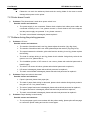
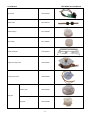
Appendix 4 Spare part list
Parts
Part No.
Impact head
3009-903780
Print head flexible cable
7101-905477
Ribbon drive gear
8203-900490
Upper mark sensor
7600-906357
Nether mark sensor
7600-905464
Front cover micro switch
7600-905460
Back cover micro switch
7600-905461
Paper end sensor
7600-905462
Paper near end sensor
7600-905525
- 42 -
Reference Picture
Confidential
BTP-M280 Service Manual
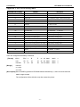
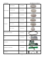
HP Sensor
7600-905463
Platen roller
8301-904701
Roller bushing
8211-900499
HP bushing
8211-900651
Paper guide part
8104-904621
Paper feed step motor
3200-904997
Printing step motor
3200-905905
Initiative gear
8203-900487
Tensioner
8203-900488
Belt gear
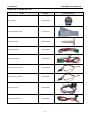
- 43 -
Confidential
Paper feed gear
Printing gear
BTP-M280 Service Manual
Platen roller gear
8203-900619
Transmission gear
8203-900594
Gear31-17
8203-901160
Transmission Gear(25-19)
8203-900489
Gear 3(42-17)
8203-901158
Gear 1(25-15)
8203-901159
Synchronization toothed belt
4930-901147
Cutter
7600-905432
Control board
7204-906053
Feed button and LED module
7600-905465
Keypad label
8205-904734
- 44 -
Confidential
BTP-M280 Service Manual
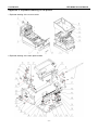
Appendix 5 Exploded drawing of the printer
1 Explored drawing of the cover module
2 Explored drawing of the main plate module
- 45 -
Confidential
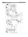
3 Explored drawing of stationary blade module
BTP-M280 Service Manual
4 Explored drawing of roller module
- 46 -
Confidential
5 Explored drawing of paper holder module
BTP-M280 Service Manual
6 Explored drawing of main control board module
- 47 -
Confidential
BTP-M280 Service Manual
Appendix 6 Part list
No
Part No
Drawing No
Name
Number
Remark
1.
8005- 904688
BTP-M280.01.02.16R
Spanner spring
1
2.
8209- 904680
BTP-M280.01.05.06R
Open button
1
8201- 904654
BTP-M280.01.05.01R
Rear cover(Without rewinder)
1
Black
8201- 904664
BTP-M280.01.05.01R
Rear cover(Without rewinder)
1
White
4.
4002- 901335
ST2.9×8
Pan head self-drilling screw
10
5.
4002- 900913
ST2.9×6
Pan head self-drilling screw
50
8201-904655
BTP-M280.01.05.02R
Front cover
1
Black
8201- 904665
BTP-M280.01.05.02R
Front cover
1
White
8201-904669
BTP-M280.01.05.07R
LOGO board
1
Black
8201-904668
BTP-M280.01.05.07R
LOGO board
1
White
8104- 904626
BTP-M280.01.07.01R
Manual cutter
1
8201- 904657
BTP-M280.01.05.04R
Lower cover
1
Black
8201-904667
BTP-M280.01.05.04R
Lower cover
1
White
Feed button
1
3.
6.
7.
8.
9.
10.
7600-905465
11.
8209- 900912
TH200.01.08R
Feed button cap
1
12.
8205- 904734
BTP-M280.BS.02R
Feed button label
1
8201- 904656
BTP-M280.01.05.03R
Middle cover
1
Black
8201-904666
BTP-M280.01.05.03R
Middle cover
1
White
8201- 904658
BTP-M280.01.05.05R
Middle cover plate
1
Black
8201-904663
BTP-M280.01.05.05R
Middle cover plate
1
White
15.
8299- 904675
BTP-M280.01.01.12R
Impact block
1
16.
4002- 900901
ST2.6*10
Pan head self-drilling screw
2
17.
8299- 904671
BTP-M280.01.01.17R
Ribbon guide plate
1
18.
3004-904961
Print head
1
19.
8099-904692
BTP-M280.01.01.09.03R
Dust proof woolen washer
2
20.
8211-900651
BTP-M270.01.06.14R
Left position bushing
2
21.
8299-904678
BTP-M280.01.01.16R
Carriage
1
22.
8104-904609
BTP-M280.01.01.09.01R
Carriage spring plate
1
23.
8299-904676
BTP-M280.01.01.14R
Eccentricity bushing
2
24.
8102-904610
BTP-M280.01.01.10.01R
Carriage holder plate
1
25.
8102-904602
BTP-M280.01.01.02.01R
Mechanism left plate
1
26.
4002- 900913
ST2.9×6
Pan head self-drilling screw
6
27.
8005- 902358
BK-S216.01.04.19R
Lock hook spring
1
28.
3200- 901678
Carriage motor
1
29.
4930- 901147
96 MXL 019
Dentform belt
1
30.
4400- 900292
Φ3.5
E-ring
7
31.
8203- 900488
BTP-M270.01.03.18.04R
Tight wheel
1
32.
8102- 904608
BTP-M280.01.01.08.01R
Fasten plate
1
33.
8102- 904606
BTP-M280.01.01.06.01R
Ribbon drive plate
3
34.
7600-905463
HP sensor
1
35.
4000- 900297
Screw module
6
13.
14.
M3×8
- 48 -
Confidential
BTP-M280 Service Manual
36.
8203-901159
BSC-2000A.01.24R
Scan gear 1
1
37.
8203-900490
BTP-M270.01.03.18.07R
Ribbon drive gear
1
38.
8203-901158
BX-7R
Gear 3
2
39.
8203-900487
BTP-M270.01.03.18.02R
Driving wheel
1
40.
8203-900489
BTP-M270.01.03.18.05R
Transmission gear
1
41.
4400-900294
Φ2
E-ring
2
42.
8299-904670
BTP-M280.01.01.15R
Gear dust proof cover
1
43.
8102-904601
BTP-M280.01.01.01.01R
Mechanism right plate
1
44.
8001-904643
BTP-1000PT.01.01.14R
Guide shaft
1
45.
8299-904674
BTP-M280.01.01.12R
Plastic swing block
1
46.
8102-904607
BTP-M280.01.01.07.01R
Ribbon support plate
1
47.
6101-901146
Ribbon
1
48.
4006-900295
Sphere head screw
2
49.
3100-905432
Stationary blade
1
50.
8299-905382
BTP-M280.01.01.22R
Stationary blade plate
1
51.
8102- 904603
BTP-M280.01.01.03.01R
Stationary blade plate
1
52.
8102- 904605
BTP-M280.01.01.05.01R
Stationary blade left support plate
1
53.
8102- 904604
BTP-M280.01.01.04.01R
Stationary blade right support plate
1
54.
8001-904642
BTP-M280.01.01.19R
Stationary blade shaft
1
55.
3100-905432
Moving blade
1
56.
8102- 904616
BTP-M280.01.02.05.01R
Moving blade fixing plate(Without rewinder)
1
57.
8102-904612
BTP-M280.01.02.01.01R
Roller holder
1
58.
8102-904613
BTP-M280.01.02.02.01R
Roll left holder
1
59.
8203-901160
BTP-L340.01.05.01.10-AR
Gear 31-17
1
60.
8203-900594
BK-L2163DKPV.01.01.01R
Transmission gear
1
61.
4400-900292
Φ3.5
E-ring
3
62.
8001-904647
BTP-M280.01.02.09R
Hook shaft
1
63.
8203-900619
BK-L2163DKPV.01.01.02R
Print roller gear
1
64.
4400-900627
Φ4
E-ring
4
65.
8301-904701
BTP-M280.01.02.11R
Roller
1
66.
8102-904615
BTP-M280.01.02.04.01R
Hook
1
67.
8299-904682
BTP-M280.01.02.13R
Upper channel plate
1
68.
8102-904617
BTP-M280.01.02.07.01R
Print underlay plate
1
69.
8102-904614
BTP-M280.01.02.03.01R
Roller tight holder
1
70.
8211-900499
BTP-M270.01.06.11R
Roller bushing
1
71.
8202-904679
BTP-M280.01.02.12R
Spanner
1
72.
8001-904648
BTP-M280.01.02.10R
Rear shaft
1
73.
8299-904708
BTP-M280.01.03.10R
Vertical paper holder
1
74.
8207-900508
BTP-R280.01.01.11R
Sensor holder(Horizontal)
1
75.
7600-905525
Paper near end sensor
2
76.
8299-900507
BSC-R280.01.01.01R
Paper near end sensor spanner
1
77.
8203-900484
BTP-M270.01.03.06R
Sensor spanner
1
78.
8102-904620
BTP-M280.01.03.04.01R
Paper holder left plate
1
79.
8302-904630
BTP-M280.01.03.14R
Damping washer
1
M3×5
- 49 -
Confidential
80.
3200-904997
81.
8207-900509
82.
BTP-M280 Service Manual
Paper feeding motor
1
BTP-R280.01.01.12R
Sensor holder(Vertical)
1
8203-901160
BTP-L340.01.05.01.10-AR
Gear 31-17
1
83.
8299-904683
BTP-M280.01.03.12R
Dust proof cover of sensor
1
84.
7600-905464
Lower mark sensor
1
85.
8001-904650
BTP-M280.01.03.16R
Press paper shaft
1
86.
4002-900282
ST2.2×4
Pan head self-drilling screw
2
87.
8102-904618
BTP-M280.01.03.02.01R
Press paper wheel plate
1
8299-904677
BTP-M280.01.03.07R
Press paper wheel
2
8399-904702
BTP-M280.01.03.15R
Press paper bushing
2
89.
8104-904622
BTP-M280.01.03.06.01R
Press paper wheel spring plate
1
90.
8299-904672
BTP-M280.01.03.11R
Paper sensor plate
1
91.
7600-905462
Paper sensor
1
92.
8104-904621
BTP-M280.01.03.05.01R
Paper guide sprint plate
1
93.
8102-904619
BTP-M280.01.03.03.01R
Paper holder right plate
1
94.
7600-905461
Mirco-switch for upper cover
1
95.
8299-904673
BTP-M280.01.03.13R
Paper roller guide
1
96.
8299-904681
BTP-M280.01.03.09R
Paper holder
1
97.
8299-901155
BTP-R280.01.01.10R
Paper roller shaft
3
98.
7204-905519
Main control board
1
99.
8102-904623
BTP-M280.01.04.02.01R
Interface plate
1
100.
8102-904627
BTP-M280.01.04.01.01R
Control board cover
1
8103-900250
BTP-2002CP.01.02.05R
USB plate
1
8103-900144
BTP-2002CP II.01.02.04R
36 Pin parallel interface plate
1
8103-900249
BTP-2002CP.01.02.06R
25 Pin serial interface plate
1
8103-900397
YTW-01.01R
Ethernet interface plate
1
4000-900988
M2.5×5
Pan head screw
2
7201-902227
EZUPORT1.2
USB interface board
1
7201-902228
EZPNIBPORT1.11
36 Pin bi-direction parallel interface board
1
7201-902277
IFWI1.01
JK-W01 WLAB interface board
1
7201-900520
S25PORT1.2
25 Pin serial interface board
1
104.
8210-900378
BTP-2000CPII.01.02.05R
Guide plate
1
105.
4001-900165
M3×5
Sink-head screw
2
106.
4000-900057
M2×8
Pan head screw
2
107.
7600-905460
Power switch for front cover
1
108.
4000-900300
Pan head screw
4
88.
101.
102.
103.
M3×6
- 50 -
Confidential
BTP-M280 Service Manual
Appendix 7 Outline drawing
- 51 -
Confidential
BTP-M280 Service Manual
Appendix 8 Main board layout
Top side of Main control board
Bottom side of Main control board
- 52 -
Confidential
BTP-M280 Service Manual
Appendix 9 Lubrication
Please lubricate the printer according to following principle:
1)
Please lubricate joint point of gear and gear shaft, do not lubricate gear tooth.
2)
Please do not lubricate platen roller and its bushing.
3)
Please lubricate the carriage guide shaft in maintenance.
Notice:
Lubricate is special kind (EM50), please ask reseller or manufacture for advice.
- 53 -