1
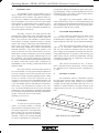
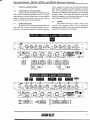
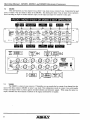
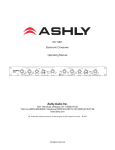
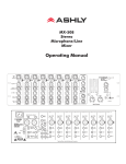
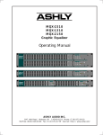
XR1001 XR2001 XR4001 Electronic Crossover Operating Manual Channel 1 XR1001 4 Stereo Two-Way Mono 3-Way El ec tr. Crossover 24 dB/ Oc tave U 6 Channel 2 U 4 3 7 8 2 8 0 H ig h 10 Lo w Mid Mute 12 6 8 1 XR2001 Four Channel Two Way Stereo Thre e Way Ele ctroni c Crossover 24 dB/ Oc tave U 4 8 1 9 Mute 0 H igh 10 Low Mid 12 Output Level dB 2 U 6 4 8 0 Range Channel 2 U 4 6 3 8 1 U 4 Mute 1 Stereo 2-way Mono 3-way 9 0 High 10 Lo w Mid Output Level 12 dB 400 40 2 4 8 9 Peak 0 U 4 Mute Stereo 2-way Mono 3-way U 2 dB 4 8 Output Level Range H igh 12 Peak Input Level Mono 3-Way Input Level 4 Norm 2 dB 4K 8K Hz 800 6 7 8 1 9 0 Crossover Frequency Response U 2 ÷1 0 400 40 9 10 3 2K 0 H igh 10 8 1K 9 7 0 Frequency 3 500 6 2 1 8K Hz 800 9 Mute U 3 Norm ÷1 0 7 10 Peak Input Level Range Mono 3-Way Input Level Crossover 6 6 2 8 9 0 4K 400 40 Response 1 9 0 Lo w 10 Input Level 12 H igh 3 7 1 10 9 7 1 2K 3 500 6 2 1K 9 Mute 0 H igh 10 6 Crossover Frequency 6 6 8 Channel 4 Mode 2 400 40 2 dB 4K 8K Hz 800 U 3 Norm ÷1 0 7 Output Level 3 7 1 Range Frequency 6 2 4K 8K Hz 800 Crossover Response U 3 Norm ÷1 0 3 500 Mute 9 0 Lo w 10 Power 2K 8 1 9 4 7 2 U 1 9 12 Response 2 0 Lo w 10 10 Input Level 1K 6 6 3 7 4 Mute 4 2K 3 500 H igh 3 7 1K 9 Mute 9 1 6 Channel 3 2 8 0 H igh 10 Mode 2 9 Peak 6 6 7 Output Level U U 3 Mute 2 9 3 7 1 8K Hz 800 Crossover Frequency Response 8 Mono 3-way 2 4K 400 40 4 7 0 Lo w 10 10 3 Norm ÷10 3 500 6 1 Peak Input Level 4 2K 9 9 0 Low 10 0 Range 7 2 Mute 9 1 U Mode 2 8 1K 6 6 3 7 4 3 7 Ste reo 2- way Crossover Frequency Response Channel 1 U 4 3 dB 6 2 4K 8K Hz 800 400 40 2 U 3 Norm ÷1 0 3 500 Output Level 2 4 2K 9 9 1 0 Lo w 10 Power 1K 7 Mute 2 9 1 6 6 3 Range 10 Peak Input Level Mono 3-Way Input Level Channel 1 4 U 6 3 U 6 3 9 10 0 Stereo F our Way El ectronic Crossover 24 dB/ Oc tave Lo w U 6 3 9 10 0 Low-Mid U 9 10 0 High-Mid 1K 6 6 3 7 8 2 1 Mute 4 7 8 2 1 Mute 4 7 8 2 1 XR4001 4 7 2 8 0 Mute 12 Mute H igh dB 2 Respons e Output Level Norm ÷1 0 3 500 9 10 1 6 2K 9 400 40 4K 8K Hz 800 1K 12 2 dB Range Low/Low-Mid Respons e Norm ÷1 0 3 500 400 40 4K 6 2K 9 4K 8K Hz 800 9 3 2 12 1.2K dB Low-Mid/Hi-Mid Range 2K 120 Respons e 4 8K Hz Norm ÷1 0 6 7 8 9 10 1 16K 24K 0 2 .4 K Hi-Mid/High U 3 2 Peak Input Level Range Channel 2 4 U 3 4 U 6 3 9 10 0 Lo w U 6 3 0 9 10 Low-Mid U 3 0 9 10 High-Mid Output Level 8 9 10 1 Mute 6 6 0 H igh Mute 6 1K 7 8 2 1 Mute 4 7 8 2 1 Mute 4 7 8 2 1 Power 6 7 2 2K 9 3 500 12 dB 2 Respons e 400 40 Norm ÷1 0 4K 8K Hz 800 Low/Low-Mid 2 dB Respons e 400 40 4K 6 2K 3 500 12 Range 1K 9 4 3 Norm ÷1 0 4K 8K Hz 800 Low-Mid/Hi-Mid Range 9 3 12 2 dB Respons e 2K 8K Norm ÷1 0 1.2K 120 Hz 24K Hi-Mid/High 8 0 2 .4 K Range 6 7 1 16K U 2 9 10 Peak Input Level ASHLY AUDIO INC. 847 Holt Road Webster, NY 14580-9103 Phone: (716) 872-0010 Toll-Free: (800) 828-6308 Fax: (716) 872-0739 Internet: http://www.ashly.com/ Operating Manual - XR1001, XR2001, and XR4001 Electronic Crossovers Table Of Contents 1 INTRODUCTION . . . . . . . . . . . . . . . . . . . . . . . . . . . . . . . . . . . . . . . . . . . . . . . . . . . . . . . . 3 2 UNPACKING . . . . . . . . . . . . . . . . . . . . . . . . . . . . . . . . . . . . . . . . . . . . . . . . . . . . . . . . . . . . 3 3 AC POWER REQUIREMENTS . . . . . . . . . . . . . . . . . . . . . . . . . . . . . . . . . . . . . . . . . . . 3 4 SECURITY COVERS . . . . . . . . . . . . . . . . . . . . . . . . . . . . . . . . . . . . . . . . . . . . . . . . . . . . 3 5 CONTROLS . . . . . . . . . . . . . . . . . . . . . . . . . . . . . . . . . . . . . . . . . . . . . . . . . . . . . . . . . . . . . 5.1 Power Switch . . . . . . . . . . . . . . . . . . . . . . . . . . . . . . . . . . . . . . . . . . . . . . . . . . . . . . . . 5.2 Input Level . . . . . . . . . . . . . . . . . . . . . . . . . . . . . . . . . . . . . . . . . . . . . . . . . . . . . . . . . . 5.3 Crossover Frequency . . . . . . . . . . . . . . . . . . . . . . . . . . . . . . . . . . . . . . . . . . . . . . . . . . 5.4 Response . . . . . . . . . . . . . . . . . . . . . . . . . . . . . . . . . . . . . . . . . . . . . . . . . . . . . . . . . . . . 5.5 Output Level . . . . . . . . . . . . . . . . . . . . . . . . . . . . . . . . . . . . . . . . . . . . . . . . . . . . . . . . . 5.6 Clip Indicator . . . . . . . . . . . . . . . . . . . . . . . . . . . . . . . . . . . . . . . . . . . . . . . . . . . . . . . . 4 4 4 4 4 5 5 6 AUDIO CONNECTIONS AND CABLES . . . . . . . . . . . . . . . . . . . . . . . . . . . . . . . . . . . 6.1 Balanced . . . . . . . . . . . . . . . . . . . . . . . . . . . . . . . . . . . . . . . . . . . . . . . . . . . . . . . . . . . . 6.2 Unbalanced . . . . . . . . . . . . . . . . . . . . . . . . . . . . . . . . . . . . . . . . . . . . . . . . . . . . . . . . . . 6.3 Inputs . . . . . . . . . . . . . . . . . . . . . . . . . . . . . . . . . . . . . . . . . . . . . . . . . . . . . . . . . . . . . . . 6.4 Outputs . . . . . . . . . . . . . . . . . . . . . . . . . . . . . . . . . . . . . . . . . . . . . . . . . . . . . . . . . . . . . . 6.5 Mono Low Output . . . . . . . . . . . . . . . . . . . . . . . . . . . . . . . . . . . . . . . . . . . . . . . . . . . . 6.6 System Phase . . . . . . . . . . . . . . . . . . . . . . . . . . . . . . . . . . . . . . . . . . . . . . . . . . . . . . . . 6 6 6 6 6 6 6 7 TYPICAL APPLICATIONS . . . . . . . . . . . . . . . . . . . . . . . . . . . . . . . . . . . . . . . . . . . . . . 7.1 Connecting Into a Sound System . . . . . . . . . . . . . . . . . . . . . . . . . . . . . . . . . . . . . . . 7.2 Speaker Placement . . . . . . . . . . . . . . . . . . . . . . . . . . . . . . . . . . . . . . . . . . . . . . . . . . . . 7.3 XR1001 . . . . . . . . . . . . . . . . . . . . . . . . . . . . . . . . . . . . . . . . . . . . . . . . . . . . . . . . . . . . . 7.4 XR2001 . . . . . . . . . . . . . . . . . . . . . . . . . . . . . . . . . . . . . . . . . . . . . . . . . . . . . . . . . . . . . 7.5 XR4001 . . . . . . . . . . . . . . . . . . . . . . . . . . . . . . . . . . . . . . . . . . . . . . . . . . . . . . . . . . . . . 7 7 7 7 8 8 8 TROUBLESHOOTING TIPS . . . . . . . . . . . . . . . . . . . . . . . . . . . . . . . . . . . . . . . . . . . . . 9 9 DIMENSIONAL DIAGRAM . . . . . . . . . . . . . . . . . . . . . . . . . . . . . . . . . . . . . . . . . . . . . . 9 10 SPECIFICATIONS . . . . . . . . . . . . . . . . . . . . . . . . . . . . . . . . . . . . . . . . . . . . . . . . . . . . . 10 11 WARRANTY INFORMATION . . . . . . . . . . . . . . . . . . . . . . . . . . . . . . . . . . . . . . . . . . . 10 12 SCHEMATICS . . . . . . . . . . . . . . . . . . . . . . . . . . . . . . . . . . . . . . . . . . . . . . . . . . . . . . 11-15 2 Operating Manual - XR1001, XR2001, and XR4001 Electronic Crossovers 1. INTRODUCTION Your ASHLY crossover is the product of an intensive research effort which combined a reexamination of traditional crossover theory with practical field use. Over the years, a number of refinements and new models have been added to our crossover series, but the original design goals have remained the same: to produce a crossover which is sonically accurate, is flexible enough to suit a wide variety of systems, and affords maximum protection for speakers and drivers. transportation damage should the unit again require packing and shipping. In the event that damage has occurred, immediately notify your dealer so that a written claim to cover the damages can be initiated. The right to any claim against a public carrier can be forfeited if the carrier is not notified promptly and if the shipping carton and packing materials are not available for inspection by the carrier. Save all packing materials until the claim has been settled. 3. All Ashly crossovers are based upon the same powerful state-variable filter circuit, which guarantees that two adjacent frequency band outputs always remain in phase. Our crossovers offer a number of useful and unusual features, including continuous tuning, a response control, and a unique output stage which maintains low noise at any level setting. These models also include a 200:1 tuning range, output mute switches, and both TRS and XLR connectors. Like other Ashly products, your crossover features low noise and distortion, active balanced inputs, a peak level indicator, a precision regulated power supply, protection against abnormal input or output conditions, and rugged mechanical construction. Conservative design and an unusually thorough procedure for quality control have earned Ashly a reputation for dependability in the recording, sound reinforcement, and broadcast fields. Due to the similarity of the operating controls on our various models, we have prepared this one manual to cover our complete crossover line. Specific notes on each model will be found in separate application notes. Many owners are unaware of the ease with which you can reconfigure your crossover for nonstandard operation. For example, a 4-way crossover can easily be used as a mono 2-way with tunable subsonic and ultrasonic cutoff filters, and a stereo 3-way can function as a mono 5-way crossover. No internal modifications are necessary, and audio performance is not compromised. In addition, this manual covers normal setup and operation and offers troubleshooting tips. Please take time to read it before operating your crossover. 2. AC POWER REQUIREMENTS Unless otherwise indicated on the back of the unit, all crossovers should be connected to a 3-wire grounded outlet supplying 120 Volts, 50-60 Hz. Some export models are 240 volts, and are labeled accordingly. This unit will perform normally from 92 to 130 volts AC. A “brownout” condition occurs when available AC power falls low enough to take the unit’s DC power supply out of regulation, increasing noise and lowering signal headroom. In general, avoid powering your audio system with AC circuits that additionally run large refrigeration compressors, air conditioners, electric heaters, lighting systems, etc. This unit has an internal line fuse. In the unlikely event that the fuse should blow, refer the product to a qualified service technician. Power consumption is 15 watts. 4. SECURITY COVERS For installations where it is desirable to protect the front panel controls from tampering or accidental misadjustment, use the Ashly security cover, which is available in both single and double rack space sizes. Installation is simple and does not require removal of the equipment from your rack. See your Ashly dealer for details. UNPACKING As a part of our system of quality control, every Ashly product is carefully inspected before leaving the factory to ensure flawless appearance. After unpacking, please inspect for any physical damage. Save the shipping carton and all packing materials , as they were carefully designed to reduce to minimum the possibility of Ashly Security Cover Installation 3 Operating Manual - XR1001, XR2001, and XR4001 Electronic Crossovers 5. CONTROLS Every Ashly crossover has the following controls: a Power Switch, an Input Level control, a Crossover Frequency (Hz) control and Range Switch for each dividing point, a Response (dB) control, Output Level controls with Mute Switches, and a Peak Indicator LED. The XR1001 and XR2001 also have a Mode Switch for selecting between 2-way and 3-way operation. Power Switch This switch connects AC power to the rest of the unit. You will know power is on when one of the crossover frequency range LED indicators is lit. If there is no light, check to see if the unit is plugged in to a live outlet. If there is still no light, the internal AC line fuse may have blown. Refer the unit to a qualified service technician for fuse replacement. To allow a wider tuning range, our crossovers use a recessed range switch for each frequency control. LED indicators provide range status as soon as the unit is powered on. The range switch divides the frequency indicated on the frequency control by 10 and gives a total range of 200:1 for each control. Avoid accidental damage to speakers by muting the outputs before changing the range switch. Carefully plan and check the frequency range selected to each driver before sending audio signals to your speakers. 5.1 5.2 Input Level This control can boost incoming signal up to +8dB before it reaches the filters, or attenuate the signal so that it is fully off. Maximum input level is +23dBu. The “U” shown at the 12:00 position indicates “unity gain” of the input section. We recommend setting this control at unity and controlling system levels either prior to the crossover or at the output level controls. 5.3 Crossover Frequency This infinitely variable control allows you to select an appropriate crossover point for your speakers. Turning the knob clockwise moves the crossover point to a higher frequency, while turning it counterclockwise moves it to a lower frequency. Crossover frequencies are marked on standard ISO 1/3 octave center frequencies with each octave calibrated. Calibration accuracy is very good, typically within 1/3 octave or better. If greater accuracy than this is necessary, measure the actual crossover frequency with an accurate oscillator/frequency counter. 4 The choice of crossover frequencies depends on the type of speakers being used, personal taste, room acoustics, and many other factors. Experiment to see what works best for you. CAUTION: High frequency compression drivers may be destroyed by the use of too low a crossover frequency. Follow the driver manufacturer’s recommendations carefully. Make sure the range switch is properly set. You may want to install a security cover if the unit is accessible to untrained people. 5.4 Response This control, found adjacent to the crossover frequency control, adjusts the damping of the filter affecting the response shape of the filters at the crossover point (see drawing). The dial calibrations refer to the amount of attenuation effected by the filter at the crossover frequency, i.e., a setting of 3dB means that the filter’s high-pass and low-pass outputs are each “rolled off 3dB at the crossover point”. This describes Butterworth filter response, or a gentle 3dB peak at the crossover point when the two filter output signals overlap. To obtain a flat signal, or “Linkowitz-Riley” response through the crossover region, set the Response control to “6”. This attenuates each output of the filter by 6dB at the crossover point (two identical signals added together yield a +6dB increase). To obtain a notch at the crossover point, turn down the response control past “6” to best suit your needs. Operating Manual - XR1001, XR2001, and XR4001 Electronic Crossovers The purpose of this control is to help offset the inaccuracies inherent in typical loudspeakers, thereby helping you to achieve a flat system response. If you use a spectrum analyzer to set up your system, adjust the response control to obtain the flattest response through the crossover region before any equalization is applied to the system. If adjusting by ear, we recommend an initial setting of 6dB. Adjust from this point if the system appears to have an excess or deficiency of level at the crossover point. NOTE: The Response control is not a “slope” control. A 12dB/octave crossover will always have a slope of 12dB/octave regardless of the setting of this control. Likewise, a 24dB/octave crossover will always have a slope of 24dB/octave. The Response control only affects filter response shape in the immediate vicinity of the crossover frequency; the ultimate crossover slope is a fixed parameter. 5.5 Output Level The crossover’s output stage operates at unity gain with the output level controls set at “U”. Max gain of the output stage is +15dB. In a typical setup, power amplifier input level controls should be run “full-on”, with level control being accomplished at the crossover. Adjust the crossover level controls for best system balance. Keep in mind that in any multi-amplified system, the higher frequency speakers tend to be more efficient. Expect to run the higher frequency level controls at a somewhat lower setting than the low frequency level controls to obtain proper frequency response. Note that horn and compression driver combinations are much more efficient than cone speakers, often by 12 to 20dB! When cones and compression drivers are used together, you should expect a much lower level setting for the horns (all other factors being equal) to compensate for this difference and obtain proper balance. Output Mute switches allow you to isolate individual or grouped outputs for listening tests without affecting the settings of any other outputs. 5.6 Clip Indicator Ashly crossovers feature a peak detection circuit which monitors signal level at several critical points in the crossover: input, filters, and outputs. The LED will flash when signal levels of +20dBu are reached anywhere in the crossover. Since our crossovers have a nominal 23dB of headroom referenced to a standard operating level of 0dBu (.77 Volts), a flashing LED warns you that you are only 3dB from clipping. Since peak levels are monitored at several key circuit points, the clip LED can be used to isolate the source of any overload. If the LED flashes even though all input and output levels are turned down, the signal being fed to the crossover is excessive. If the LED flashes when you turn the Input level control up (with the outputs still turned down), the overload is occurring in the filter sections, and you should back the Input level down a bit. If the LED first flashes when you turn the output level controls up, then the overload is occurring in the output stage. In this case, if your power amplifier controls are at full gain, you are probably severely overdriving your amplifier. 5 Operating Manual - XR1001, XR2001, and XR4001 Electronic Crossovers 6. AUDIO CONNECTIONS AND CABLES 6.1 Balanced Your crossover is provided with two different connector types, wired in parallel. 1/4 inch stereo phone jacks and three pin XLR type connectors will allow interfacing to most professional audio products, with pin 2 hot (+) and pin 3 (-). The inputs and outputs can be used either balanced or unbalanced. We recommend balanced connections between all components in your system, as this minimizes ground-loop or induced hum and noise. Tip (+) Ring (-) Sleeve (Ground) Stereo Phone Plug used for balanced Pins are numbered in the connector insert. 2 = (+) 3 = (-) 1 = (gnd) XLR Male 6.2 Unbalanced If either inputs or outputs are used unbalanced, the signal is on the (+) connection and the (-) connection must be tied to ground. A mono phone plug used as an unbalanced connection will automatically ground the ring of the jack which is the (-) connection. When using a stereo plug or XLR connector for unbalanced input or output connections, the signal (-) MUST be tied to ground, or loss of signal level may result. Tip (+) Sleeve (Ground) Mono Phone Plug used for unbalanced 2 = (+) 3 = (gnd) 1 = (gnd) XLR Male Unbalanced Audio Connectors 6 Inputs Inputs are 20KΩ active balanced, or 10KΩ unbalanced. 6.4 Outputs The outputs on Ashly crossovers are low impedance (200 ohms typical) pseudo-balanced type using both a 3-pin male XLR connector and standard 1/4" phone jack. Pseudo-balanced lines, while not carrying a truly differential signal, have an equivalent line impedance on both (+) and (-) lines. This allows for long cable runs from the crossover into balanced inputs without compromising common mode rejection of unwanted noise. To realize maximum headroom, terminate outputs into loads of 600 ohms or greater. 6.5 Balanced Audio Connectors Pins are numbered in the connector insert. 6.3 Mono Low Output Ashly models XR2001 and XR4001 have an additional jack labeled MONO LOW OUT. This output represents the sum of low frequency outputs of both channels, and is a function of BOTH low level controls. It is typically used for driving mono sub-woofers in a stereo system, reducing the number of power amps needed. Connectors and wiring are the same as the other outputs. If you are using a mono low output, you may also use the normal low frequency outputs to drive other speaker systems; any or all of the low frequency outputs may be used at any given time without interaction between outputs. 6.6 System Phase The outputs of all Ashly crossovers are in phase with the input. Assuming that your power amplifiers do not invert phase (most do not), the signals from all your amps should be in phase. If all speakers are the same brand, it is easy to keep them in phase. With different brands of speakers used together, phasing becomes a little more confusing. It is important to keep all the speakers within each band in phase with each other, and equally important to keep all bands of the system in phase as well. If this is not done, loss of level and pattern control at the crossover frequency will result. Phase of CONE speakers can be checked by connecting a 1.5 volt battery to the speaker and observing which way the cone moves. Don’t try this with compression drivers! The most common convention is that (+) voltage on the (+) terminal moves the cone forward. A notable exception to this convention is JBL. A (+) voltage on the red terminal of a JBL speaker moves the cone backward. If all your speakers are the same brand, just connect them all the same way; if not, it’s best to test. Unfortunately, compression drivers cannot be tested this way. Ask the driver manufacturer. Operating Manual - XR1001, XR2001, and XR4001 Electronic Crossovers 8.4 8. TROUBLESHOOTING TIPS 8.1 No Output Check AC power - are LED indicators on? Check in/out connections, are they reversed? Are you sure you have input signal? 8.2 Peak light flashes frequently The level is too high somewhere in the crossover. Try turning down individual output levels and then the input until the peak LED stays off. If the peak LED continues to flash when all of the crossover level controls are turned down, then the crossover is being fed excessively high levels from a previous piece of equipment. Turn down your driving source! 8.3 Distorted sound Is the peak light flashing? If it is, an overload is occurring within the crossover, and may also be occurring in other parts of the system. If the peak light is not flashing, the distortion is occurring somewhere outside the crossover. 9. Excessive hum or noise Hum will usually be caused by a “ground loop” between components. Try using the suggested balanced input and output hookups if the other pieces of equipment used in conjunction with your crossover have balanced inputs and outputs. Noise can be caused by insufficient drive signal. Ashly crossovers provide the best noise and headroom performance when the input signal is 0 to +4dBu level and power amplifier sensitivity is higher than 1 volt. Unshielded cables, improperly wired connections, and cable with broken strands (shorts, etc.) are the most common problems. Please properly maintain and inspect your wiring first. If you still need help, get in touch with your Ashly dealer or call Ashly direct - (800) 828-6308. In New York State dial (716) 872-0010. DIMENSIONAL DIAGRAM 9 Operating Manual - XR1001, XR2001, and XR4001 Electronic Crossovers 10. SPECIFICATIONS 10.1 Input Level Control 11. -∞ to +8.5dB 10.2 Damping/Response WARRANTY INFORMATION We thank you for expression of confidence in Ashly products. The unit you have just purchased is protected by a limited five year warranty. To establish the warranty, you must first complete and mail the warranty card attached to your product. 2dB - 12dB Fill out the information below for your records. 10.3 Output Level Control -∞ to +15dB 10.4 Input Impedance Model Number ______________________ Serial Number _______________________ 20KΩ Balanced Dealer _____________________________ 10.5 Output Impedance 200Ω Quasi-Balanced 10.6 Maximum Input Level Date of Purchase _____________________ Dealer’s Address _____________________ +23dBu ___________________________________ 10.7 Maximum Output Level +23dBu 10.8 Frequency Response 10.9 Distortion ±.5dB 20Hz-20KHz ___________________________________ Dealer’s Phone ______________________ Salesperson _________________________ <.05% THD (+10dBu 20Hz-20KHz) 10.10 Slew Rate 6V/µS 10.11 Hum and Noise <-90dBu unweighted 20Hz-20KHz 10.12 Power Requirements 120VAC 50-60Hz 92VAC Minimum 240VAC Available 15 Watts Max 10.13 10 Shipping Weight XR1001: XR2001: XR4001: 8 lbs. 10 lbs. 10 lbs. OTHER INFORMATION: Operating Manual - XR1001, XR2001, and XR4001 Electronic Crossovers 13. SCHEMATICS: 11 Block Diagram: XR-1001, XR-2001 Operating Manual - XR1001, XR2001, and XR4001 Electronic Crossovers 12 Schematic Diagram: XR-1001, XR-2001 Operating Manual - XR1001, XR2001, and XR4001 Electronic Crossovers 13 Block Diagram: XR-4001 Operating Manual - XR1001, XR2001, and XR4001 Electronic Crossovers 14 Schematic Diagram: XR-4001 Operating Manual - XR1001, XR2001, and XR4001 Electronic Crossovers 15 Operating Manual - XR1001, XR2001, and XR4001 Electronic Crossovers ASHLY AUDIO INC. 847 Holt Road Webster, NY 14580-9103 Phone: (716) 872-0010 Fax: (716) 872-0739 Toll Free (800) 828-6308 Internet: http://www.ashly.com/ 1997 by Ashly Audio Corporation. All rights reserved worldwide. Printed in USA 1/97 XR Rev 4