1
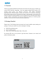
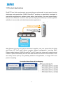
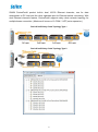
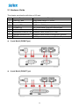
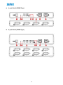
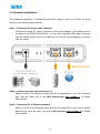
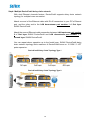
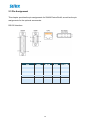
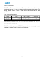
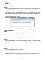
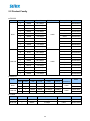
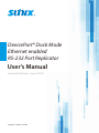
DevicePort® Dock Mode Ethernet enabled RS-232 Port Replicator User’s Manual S e con d Edit io n, J une 2014 w w w. s u n i x . c o m Driver & Manual Download Please visit SUNIX website http://www.sunix.com by searching keyword “DevicePort” or “DPKS” for detail. Scanning QR code on the product to get latest driver, firmware, user manual, and product information update. 1 User’s Manual Copyright Copyright© 2014 SUNIX Co., Ltd. All Rights Reserved. No part of this publication may be reproduced, transcribed, stored in a retrieval system, translated into any language, or transmitted in any from or by any means, photocopying, manual, or otherwise, without prior written permission from SUNIX Co., Ltd. Disclaimer SUNIX Co., Ltd. Shall not be liable for any incidental or consequential damages resulting from the performance or use of this equipment. SUNIX Co., Ltd. makes no representations or warranties regarding the contents of this manual. Information in this manual has been carefully checked for reliability; however, no guarantee is given as to the correctness of this content. In the interest of continued product improvement, this company reserves the right to revise the manual or include change in the specifications of the product described within it at any time without notice and without obligation to notify any person of such revision or changes. The information contained in this manual is provided for general use by the customers. Trademarks SUNIX is a registered trademark of SUNIX Co., Ltd. Other registered marks used herein are for identification purposes only and may be trademarks of their respective owners. Safety Information 1. Keep this User’s Manual for future reference. 2. Always read the safety information carefully. 3. Keep this equipment away from direct sunlight, or in humid or damp places. 4. Do not place this equipment in an unstable position, or on vibrating surface before setting it up. 5. Do not use or place this equipment near magnetic fields, televisions, or radios to avoid electronic interface that affects device performance. 6. Do not attempt to disassemble or repair the equipment or the warranty would be useless. 7. To avoid damaging your system and equipment, please make sure that your computer is off before you install the product. 2 Regulatory Compliance FCC Class B Declaration This equipment has been tested and found to comply with the limits for a Class B digital device, pursuant to part 15 of the FCC rules. These limits are designed to provide reasonable protection against harmful interference when the equipment is operated in a commercial environment. This equipment generates, uses and can radiate radio frequency energy and, if not installed and used in accordance with the instruction manual, may cause harmful interference to radio communications. Operation of this equipment in a residential area is likely to cause harmful interference in which case the user will be required to correct the interference at his own expense. Modifications not authorized by the manufacturer may void users authority to operate this device. This equipment meets the requirements of EC Electromagnetic Compatibility Directive (2004/108/EC) For EU (European Union) member users: According to the WEEE (Waste electrical and electronic equipment) Directive, do not dispose of this product as household waste or commercial waste. Waste electrical and electronic equipment should be appropriately collected and recycled as required by practices established for your country. For information on recycling of this product, please contact your local authorities, your household waste disposal service or the shop where you purchased the product. 3 Table of Contents Chapter 1 Introduction 1.1 Overview ........................................................................................................................................ 6 1.2 Package Checklist ........................................................................................................................... 6 1.3 Product Features ............................................................................................................................ 7 1.4 System Requirements .................................................................................................................... 7 1.5 Product Applications ...................................................................................................................... 8 1.6 Product Specifications.................................................................................................................. 10 Chapter 2 Hardware Installation 2.1 Hardware Guide ........................................................................................................................... 15 2.2 Hardware Installation................................................................................................................... 17 2.3 Pin Assignment ............................................................................................................................. 19 Chapter 3 Driver Installation 3.1 Windows Driver Installation ........................................................................................................ 22 3.2 Microsoft® .NET Framework 3.5 Installation ............................................................................... 28 3.3 Windows Driver Uninstallation .................................................................................................... 29 3.4 Verify Installation ......................................................................................................................... 30 Chapter 4 DevicePort® Configuration 4.1 SUNIX DevicePort Hardware Settings .......................................................................................... 32 4.2 Configure Serial Port Settings ...................................................................................................... 37 Chapter 5 Appendix 5.1 Troubleshooting ........................................................................................................................... 41 5.2 Product Family ............................................................................................................................. 46 5.3 Contact Information ..................................................................................................................... 47 4 1. Introduction SUNIX DevicePort® is the ideal choice to enable your current Legacy I/O devices networking. It works as a PCIe add-on card operation experience with Ethernet Hot-Plug capability. It can be installed in virtually any available PC system and compatible with Microsoft Windows operating systems. Users do not need to manually scan TCP/Socket or port mapping configuration when access legacy I/O port. SUNIX DevicePort® series is provided kinds of Legacy I/O ports for connecting terminals, modems, printers, scanners, cash registers, bar code readers, keypads, numeric displays, electrical scales, data acquisition equipment, and other serial devices for the PC and compatible systems. The following topics covered in this chapter: 1.1 Overview 1.2 Package Checklist 1.3 Product Features 1.4 System Requirements 1.5 Product Application 1.6 Product Specifications 5 1.1 Overview Thanks for purchasing SUNIX DevicePort® product that is the ideal choice to enable your current RS-232 devices networking. User can expand multiple RS-232 ports on PC windows based system over Ethernet connection. With SUNIX DPL2000Q High-Performance Ethernet-UART controller and exclusive I/O redirection technology, DevicePort® creates physical COM ports that support real time data communication and Ethernet-COM port hot-plug capability; user can expand RS-232 COM port easily without complex software configuration that improves deployment efficiency to achieve greater reliability in commercial and industrial automation applications. 1.2 Package Checklist Please check if the following items are present and in good condition upon opening your package. Contact your vendor if any item is damaged or missing. ■ ■ ■ SUNIX DevicePort® product Quick Installation Guide Power Jack to USB TyepA Male Cable, 120cm (4ft.) By scanning QR code on the product to get least driver, firmware, user manual, and product information update. 6 1.3 Product Features ■ Expands multiple RS-232 serial ports over Ethernet networking. ■ Works as a PCIe add-on card operating experience with Ethernet hot-plug and system auto-detect capability. ■ DevicePort® Dock mode supports secured connection between PC host and DevicePort®. (*Note 1) ■ Built-in SUNIX DevicePort® DPL2000Q High-Performance controller. ■ SUNIX DevicePort® proprietary Ethernet I/O Redirection Technology. - Port auto-mapping with real time data communication. - Physical COM port accessed via device manager. - Up to 12 COM ports working on windows system simultaneously. (*Note 2) ■ Accesses traditional COM port by using existing software and AP. ■ Low power consumption design for Green Environment. ■ 15KV ESD protection for all serial signals meets IEC-61000-4-2 standard. ■ Certified by CE, FCC, VCCI, C-Tick, BSMI, and Microsoft WHQL approval. Note: 1. To prevent on-line spy recording, DevicePort® Dock Mode limits specific Ethernet port connection, and it does not works on router or switch operation. 2. Ethernet I/O Redirection technology is SUNIX proprietary protocol for COM, LPT, and digital I/O expansion over categpry6/5 Ethernet cable. 1.4 System Requirements This section lists the hardware, operating system, and software requirements for SUNIX DevicePort. ■ ■ ■ ■ Intel® Pentium® processor 1G or above. System memory 256 MB RAM or above. Microsoft® Windows XP, 7, 8, 8.1 or above OS. Microsoft®.NET Framework 3.5 or 3.5 service pack1. (.NET Framework 4.0 or 4.5 does not support) 7 1.5 Product Applications Small PC form factor requirements grow and advance continuously to meet up-and-coming challenges and opportunities. SUNIX DevicePort® products are specifically developed to meet such requirements to replace current add-on card solution. User can expand legacy I/O ports over Ethernet connection that improves deployment efficiency to achieve greater reliability in commercial and industrial automation applications. With Ethernet hot-plug and system auto-detect capability, user can expand RS-232 COM and Printer LPT port easily without complex software configuration. Just plug RJ45 Ethernet cable between SUNIX DevicePort® and PC host side, system will create physical COM/LPT ports automatically with real time data transmit and receive communication. User can easily access port by using existing software and application, no longer TCP sock protocol compiling. DevicePort® Auto-Detect & Port-Mapping 8 SUNIX DevicePort® product built-in dual 10/100 Ethernet channels, one for data downstream to PC host and the other upstream port for Ethernet switch connecting. With dual Ethernet channels feature, DevicePort® supports daisy chain network topology for multiple boxes connection. (Maximum 4 boxes or 12 COM / 3 LPT ports expansion.) DevicePort® Daisy Chain Topology Type 1 DevicePort® Daisy Chain Topology Type 2 9 1.6 Product Specifications Serial Communication Interface RS-232 Baud rate 50bps ~115.2Kbps (Optional for 921.6Kpbs) Controller SUNIX DPL2000Q Stop bit 1, 1.5, 2 BUS Ethernet Parity even, odd, none, mark, space No. of Port 2, 4, 8, 16 or 32-port (Product Dependent) Flow Control Xon/Xoff (software) FIFO 1Kbyte Hardware / per port Connector DB9 Male Signal DCD, TxD, RxD, RTS, CTS, DTR, DSR, GND, RI Protection ±15KV ESD IEC6000-4-2 Air Discharge ±8KV ESD IEC61000-4-2 Contact Discharge ±4KV ESD IEC61000-4-2 Level2 Line-to-Line Ethernet Communication Speed 2-port (*Note 1) Upstream to Ethernet Switch Downstream to PC Host 10/100 Mbps, auto MDI/MDIX Connector RJ45 Magnetic Isolation Protection 1.0K Built-in Number of Ports Power Requirements Input Voltage 5 to 12VDC Power Consumption 2.5W @ 5VDC Connector DC-Jack Driver Support Microsoft Client XP / 7 / 8 / 8.1 (X86/X64) Microsoft Server 2003 / 2008 / 2012R2 (X64) Regulatory Approvals Hardware EMC Software Driver Microsoft WHQL Windows Microsoft Client: XP/7/8/8.1 (X86/X64) Microsoft Server: 2003/2008/2012R2 (X64) EUR: CE EN55022 Class B, EN55024 US: FCC Part 15 Class B TAIWAN: BSMI: CNS13438 AS/NZS: C-Tick: CISPR22 AS/NZS JAPAN: VCCI 10 Environment Operation Temperature 0 to 45°C (32 to 113°F) Operation Humidity 5 to 95% RH (non-condensing) Storage Temperature -20 to 85°C (-4 to 185°F) Physical Characteristics Housing ABS, PC, Metal Weight (Product Dependent) Dimensions (Product Dependent) 2-port Model (DB9M Type) 11 4-port Model (DB9M Type) 4-port Model (DB44F Type) 12 8-port RS-232 (DB9M Type) 13 2. Hardware Installation This chapter includes information about hardware installation for SUNIX DevicePort®. The following topics are covered: 2.1 Hardware Guide 2.2 Hardware Installation 2.3 Pin Assignments 14 2.1 Hardware Guide This chapter provides the definitions of I/O port. No. ① Function Power DC Jack Input power range +5~12VDC ② Power LED ACT when power on ③ Mapping LED ACT when COM port mapping ready in system ④ Tx Data LED ACT when serial COM port transmit data ⑤ Rx Data LED ACT when serial COM port receive data ⑥ Downstream Ethernet Port Ethernet cable connect to PC host ⑦ Upstream Ethernet Port Ethernet cable connect to switch hub (internet) ⑧ COM Port COM port number sequence (Product Dependent) 2-port Model (DB9M Type) 4-port Model (DB44F Type) Descriptions 15 4-port Model (DB9M Type) 8-port Model (DB9M Type) 16 2.2 Hardware Installation The hardware installation of SUNIX DevicePort® is easy to carry out. Follow the steps below to connect the related devices. Step1. Connecting the power cable (adapter). Connect the single DC output connector of the power adapter to the power jack on the back of the SUNIX DevicePort®. You can use enclosed USB cable to connect external +5VDC power from PC’s USB port or an AC/DC power adapter connection from AC outlet. Step2. Connecting SUNIX DevicePort® to PC. Attach one end of the Ethernet cable with RJ-45 connectors to your PC’s Ethernet port, and the other end to the LAN downstream port number 1 of SUNIX DevicePort®. Step3. Connecting PC to Ethernet network. Attach one end of the Ethernet cable with RJ-45 connectors to your Hub or switch Ethernet port, and the other end to the LAN upstream port number 2 of SUNIX DevicePort®. 17 Step4. Multiple DevicePort® daisy chain network. With dual Ethernet channels feature, DevicePort® supports daisy chain network topology for multiple boxes connection. Attach one end of the Ethernet cable with RJ-45 connectors to your PC’s Ethernet port, and the other end to the LAN downstream port number 1 of first layer SUNIX DevicePort®. Attach the second Ethernet cable connection between LAN upstream port number 2 of first layer SUNIX DevicePort® and LAN downstream port number 1 of second layer SUNIX DevicePort®. You can repeat above operation up to the fourth layer. SUNIX DevicePort® daisy chain network topology limits maximum 4 DevicePort® boxes or 12 COM / 3 LPT ports expansion. DevicePort® Daisy Chain Topology Type 1 DevicePort® Daisy Chain Topology Type 2 18 2.3 Pin Assignment This chapter provides the pin assignments for SUNIX DevicePort®, as well as the pin assignments for the optional accessories. RS-232 Interface: PIN DCD RxD TxD DTR GND DSR RTS CTS RI DB9M 1 2 3 4 5 6 7 8 9 DB25M 8 3 2 20 7 6 4 5 22 19 RJ45 7 6 3 2 4 8 1 5 - Pin Header 1 3 5 7 9 2 4 6 8 Ethernet RJ45 Interface: SUNIX DevicePort® is provided standard Ethernet ports. According to the link type, DevicePort® uses CAT 3, 4, 5,5e UTP cables to connect to any other network device (PCs, servers, switches, routers, or hubs). Please refer to the following table for cable specifications. Cable Types and Specifications Cable Type Max. Length Connector 10BASE-T Cat. 3, 4, 5 100-ohm UTP 100 m (328 ft) RJ-45 100BASE-TX Cat. 5 100-ohm UTP UTP 100 m (328 ft) RJ-45 With 100BASE-TX/10BASE-T cable, pins 1 and 2 are used for transmitting data, and pins 3 and 6 are used for receiving data. SUNIX DevicePort® supports auto MDI/MDI-X operation. You can use a straight- through 100BASE-TX/10BASE-T cable to connect PC to DevicePort®. 20 3. Driver Installation After connecting SUNIX DevicePort® to your system successfully, please follow the step by step software installation guide to confirm how to install appropriate driver and configure the serial port settings. By scanning QR code on the product or visiting SUNIX official website http://www.sunix.com to download least driver. The driver for SUNIX DevicePort® supports Windows operating systems, and you can select your requirement in the following chapter: The following topics covered in this chapter: 3.1 Windows Driver Installation 3.2 Microsoft®.NET Framework 3.5 Installation 3.3 Windows Driver Uninstallation 3.4 Verify Installation 21 3.1 Windows Driver Installation Please refer to following instructions to install SUNIX DevicePort® driver for the first time under Windows operation system. You will need to connect SUNIX DevicePort® to PC ready, before installing the driver. (1) You can download the latest driver from SUNIX official website (http://www.sunix.com) by searching “DevicePort” or “DPKS”. (2) Please execute Setup.exe to install driver. Driver InstallShield Wizard will show up and please wait for driver install procedure running. 22 (3) Click “Next” to continue driver installation steps. (4) Select SUNIX DevicePort Control Center Utility destination location. Click “Next” to continue driver installation steps. 23 (5) Click “Install” to continue driver installation steps. (6) System will install driver automatically. It takes about one minute. 24 (7) Click “Install” to continue driver installation steps. (8) Click “Finish” to end installation steps. 25 (9) If your operation system does not include Microsoft®.NET Framework 3.5 (or 3.5 service pack1) package, Windows 8/8.1 wizard will show this warning screen as below. Please click “Download and install this feature”. (10) System will search and download required files from internet. Be sure to connect your PC to internet and system will download it automatically. You may take 10~15 minutes downloading required files, and it depends on your internet connection performance. 26 (11) After downloading Microsoft®.NET Framework 3.5 ready, system will install it automatically. Please reboot your PC to enable this new feature. Note: Under Windows XP operation system, user will not read above Microsoft®.NET Framework 3.5 required wizards. User has to download and install Microsoft®.NET Framework 3.5 (or 3.5 service pack1) software package by themself. Please refer to chapter 3.2 Microsoft® .NET Framework 3.5 Installation for more detail. 27 3.2 Microsoft® .NET Framework 3.5 Installation SUNIX DevicePort application design bases on Microsoft®.NET Framework software, and Microsoft®.NET Framework 3.5 (or 3.5 service pack1) is required. The table in this topic provides the operating system for the Microsoft® .NET Framework editions. Operating System .NET Framework Edition Remarks Windows XP n.a. User has to install .NET Framework 3.5 Windows Vista .NET Framework 3 - Windows 7 .NET Framework 3.5 - Windows 8 / 8.1 .NET Framework 4 or 4.5 User has to install .NET Framework 3.5 Server 2008 .NET Framework 4 User has to install .NET Framework 3.5 Server 2012 .NET Framework 4 or 4.5 User has to install .NET Framework 3.5 Please note that Microsoft®.NET Framework 4 or 4.5 is NOT include previous editions. User has to install Microsoft®.NET Framework 3.5 or 3.5 Service Pack 1 separately. Due to Microsoft® licensed issue, .NET Framework 3.5 setup package is not included, user can go to Microsoft official website (http://www.microsoft.com/) or search keyword “.NET Framework 3.5” to download software package. 28 3.3 Windows Driver Uninstallation Please refer to following instructions uninstall SUNIX DevicePort® driver. (1) Click on the “Programs and Features” tab in the Windows Control Panel. Start > Controller Panel > Programs and Features (2) Entry Uninstall or change a program page, and double click “SUNIX DevicePort® Control Center” to process driver uninstallation procedure. 29 3.4 Verify Installation You can use Windows “Device Manager” to verify proper installation. (1) Click on the “Programs and Features” tab in the Windows Control Panel. Start > Controller Panel > Device Manager (2) In the Device Manager window, you should see SUNIX COM port under Ports (COM & LPT). (4-port DevicePort® in this example) (3) You also can check SUNIX DevicePort® box and COM/LPT port mapping status over SUNIX DevicePort® Control Center by executing dp icon on the windows desktop system tray. 30 4. DevicePort® Configuration This chapter shows SUNIX DevicePort® and Serial COM and Printer port settings that user came with usually, such as MAC address, device name, COM port number, baud rate, and other features. The following topics covered in this chapter: 4.1 SUNIX DevicePort Hardware Settings 4.2 Configure Serial Port Settings 31 4.1 SUNIX DevicePort Hardware Settings SUNIX DevicePort® supports Ethernet hot-plug, system auto-detect, and port auto-mapping features; user can expand RS-232 COM port conveniently. (1) DevicePort® Plug-n-Play Detection After SUNIX DevicePort® drivers are installed; connecting RJ45 Ethernet cable between SUNIX DevicePort® and PC host side. You will read “DevicePort Online” information shows up on the windows desktop system tray. Conversely, after removing Ethernet cable connection between SUNIX DevicePort® and PC, you will read “DevicePort Offline” information shows up on the windows desktop system tray. Note: Be sure to keep DevicePort Control Center utility alive in your system, please do NOT close, disable or remove it from windows startup process. (2) DevicePort® Control Center Access DevicePort® Control Center by double clicking dp icon on the windows desktop system tray. You can discover DevicePort® connection status on DevicePort® Control Center utility. This is an example for a 4-port DevicePort® screen shot. 1 32 Click “+” sub-tree to open DevicePort® detail. COM port mapping status will show up on DevicePort® Control Center “DevicePort List” table. This is an example for a 4-port DevicePort® screen shot. DevicePort® Control Center utility version and driver version shows in the “About” table. Right click the DevicePort® model number and click “Properties”. You can go to DevicePort® hardware advanced settings, including device name, MAC address, and firmware update. You can read DevicePort® model number, device name, MAC address, firmware version in the General table. 33 (3) Device Name DevicePort® “Device Name” is specially designed to allow easy identification of the multiple DevicePort® boxes which are connected to PC host. You can input maximum 20 characters. Click “Set Device Name” to save settings. (4) MAC Address MAC Address (Media Access Control Address) is a unique identifier assigned to network DevicePort® for communications on the physical network segment. To prevent MAC address conflict problem, user can modify it by himself. Click “Set MAC Address” to save settings. (3) (4) (5) 34 (5) Upgrade Firmware Download the latest firmware from SUNIX official website and click “Browse...” to select correct firmware “.bin” file. Click “Upgrade” to upgrade DevicePort® to the latest firmware version. Click “OK” to process DevicePort® firmware upgrade procedure. Users can check the progress of firmware upgrading process in status column. Please be patient of DevicePort® upgrading process. After FW upgrade process successfully, please reboot (power off and on) DevicePort®. Caution: Do NOT remove Ethernet connection or power-off DevicePort® when running firmware upgrade process. 35 (6) Export Log file When communication issue happens, user can export log file to analyze. Click icon and save log file to specified path. You could email log files to SUNIX technical support ([email protected]) to get help. 36 4.2 Configure Serial Port Settings After DevicePort® drivers are installed; please refer to following instructions to configure Serial COM settings. Please launch “DevicePort Control Center” utility first and open sub-tree of DevicePort® detail. There is COM port mapping detail on “DevicePort List” table. This is an example for a 4-port DevicePort® screen shot. Double click on the selected COM port, and users can configure serial port’s settings in this page, including Baud rate, Parity, Data bits, Stop bits, Flow Control, COM port number, RS-232 interface and Powered COM features. Click “Apply” to save settings. 37 (1) COM port Parameter Settings Baud Rate: (Default = 9600 bps) DevicePort® supports baud rate setting from 50bps to 115.2 Kbps. (High speed model up to 921.6Kbps) Data bits: (Default = 8 bits) DevicePort® supports data bits setting from 5 to 8 bit. Parity: (Default = None) DevicePort® supports parity setting including None, Even,Odd, Space, and Mark. Stop bits: (Default = 1 bit) DevicePort® supports stop bits setting 1, 1.5 or 2 bits. Stop bits will be set to 1.5 when Data bits is set to 5 bits. Flow Control: (Default = None) DevicePort® supports flow control setting including None, Hardware, and Xon/Xoff. (2) COM Port Number You can select COM Port number form COM1 to COM255. If this COM port is using now, there is a “in use” message shown. 38 (3) Interface (Product Dependent) DevicePort® supports kinds of models, including pure RS-232, pure RS-422/485 or 3-in-1 RS-232/422/485 interfaces. It depends on what kind of product you bought. (4) Powered COM (Product Dependent) DevicePort® supports COM port with +5VDC power output feature. User can enable Powered COM feature in this section. It depends on what kind of product you bought. 39 5. Appendix This chapter shows some problems that user came with usually. Also you can check it if the DevicePort® could not work properly in your system after following hardware and software installation steps. In addition, you could contact with us for detail technical product information. In this appendix, we cover the following topics: 5.1 Troubleshooting 5.2 Product Family 5.3 Contact Information 40 5.1 Troubleshooting 1. System fails to find the DevicePort® or COM/LPT port. Answer: It may cause by following issue: a. DevicePort® is not properly connected to the PC host. Be sure to use Ethernet downstream port number1 of DevicePort®. Please read chapter 2 hardware guide for detail b. Make sure DC power is properly connected to DevicePort®. You can identify it by Power LED on DevicePort®. Please read chapter 2 hardware guide for detail c. Make sure your PC’s Ethernet port is enable. You can read and check it by Controller Panel > Network and Internet > Network Connections d. After driver install ready, be sure to check “DevicePort® Control Center” service is working, you can check it on the windows desktop tray. Or you can access DevicePort® Control Center program from this link. C:\Program Files\SUNIX\DevicePort\ DevicePortControlCenter.exe e. DevicePort® hardware itself might be defective or crash. You can reset DevicePort® power again, try another PC to test it, or contact us for technical support. 41 2. My DevicePort® does not support plug-n-play feature. Answer: It may cause by following issue: a. Be sure to keep “DevicePort Control Center” utility alive in your windows desktop system tray, please do NOT close, disable or remove it. b. Be sure to keep “DevicePort Control Center” utility alive when windows startup, please do NOT disable or remove it from windows startup process. You can re-install SUNIX driver again to fix this problem. 3. There is no respond from “DevicePort Control Center”, after dis/connecting DevicePort® from/to PC host. Answer: It may cause by“DevicePort Control Center” utility crash, please reboot your computer to reset it. 42 4. How to install COM port on my system?. Answer: SUNIX DevicePort® supports Ethernet hot-plug and system auto-detect capability, user can expand RS-232 COM and LPT port easily. After driver installed ready at the first time, plug RJ45 Ethernet cable between SUNIX DevicePort® and PC host side, system will create physical COM/LPT ports automatically with real time data transmit and receive communication. User can easily access port by using existing software and application. DevicePort® runs procedure as below. Ethernet Connection ready > DevicePort® detecting > Port Mapping 5. Should I install driver for each DevicePort® boxes when Multiple DevicePort® daisy chain network. Answer: Driver install required only at the first time. So you do not need to re-install driver again for your second level DevicePort® connection. 6. How to expand more than 12 COM ports by using DevicePort® ? Answer: SUNIX DevicePort® daisy chain network topology limits maximum 4 DevicePort® boxes or 12 COM ports expansion in one windows based PC system. If you need more than 12 COM ports for your system, please contact with us for 16 or 32-port DevicePort® models. 7. Could I connect DevicePort® Dock mode to switch hub or AP routers? Answer: Yes, you can, however we do not recommend. If DevicePort® Dock mode connects to public switch hub or router, there are somebody may connect to this DevicePort® without your expecting. Second, to prevent on-line spy recording, DevicePort® Dock mode limits specific Ethernet port connection to PC host. If you want to do so, please refer to SUNIX DevicePort® Advanced mode model. 43 8. Will DevicePort® lower my Internet performances when access COM serial data at the same time? Answer: SUNIX DevicePort® product built-in dual 10/100 Ethernet channels, one for data downstream to PC host and the other upstream port to Ethernet switch. User can access internet over DevicePort® bridge. Serial data communication asks very low bandwidth; most of serial devices asks 9600bps,N,8,1 data transfer rate, so it should not cause your internet accessing trouble. According to our testing, one single 8-port RS-232 DevicePort® product expenses about 10Mbp/s data transferring rate with full loading (921Kbps, N,8,1) test. About 10% bandwidth of standard 10/100Mb network environment. However, to make sure efficient and safe communication, DevicePort® will put serial communication data from COM ports as the first priority than other internet data packages. 9. May I know system resource of COM or LPT port? Answer: SUNIX DevicePort® is an Ethernet enable devices. System or BIOS will not allocate any resource for COM or LPT ports. So COM port does not locate at any legacy ISA address 3F8, 3E8, 2F8,2E8 and LPT port does not locate at 378, 278, 3BC legacy ISA address either. 10. My DevicePort cannot communicate with my serial device, however without problem communicating over on-board COM port. Answer: Please follow up chapter 4.1 to export log file, and sent log files to SUNIX technical support to verify. 44 11. DevicePort Control Center utility initialization fails. Answer: It may cause by communicating time-gap between PC’s Ethernet driver and DevicePort® driver. DevicePort® Control Center utility does not initialize successfully when PC system booting. However, you still can execute DevicePort® Control Center program from this link: C:\Program Files\SUNIX\DevicePort\ DevicePortControlCenter.exe If above error message always happen when your PC booting, please try to update your Ethernet card’s driver from NIC (Network interface controller) vendor. Or you could send your PC system and NIC information to us to get help. 45 5.2 Product Family ■ RS-232 Mode Dock Advanced Port Connector Baud Rate 8 DB9M 8 ESD Protection PoweredCOM Model 921.6Kbps - DPKX08H00 DB9M 115.2Kbps - DPKS08H00 4 DB9M 921.6Kbps - DPKX04H00 4 DB9M 115.2Kbps - DPKS04H00 4 DB44F 115.2Kbps - DPKS04HZ0 4 DB9M 115.2Kbps 5VDC DPKS04HP0 4 DB44F 115.2Kbps 5VDC DPKS04HZP 2 DB9M 921.6Kbps - DPKX02H00 2 DB9M 115.2Kbps - DPKS02H00 2 DB9M 115.2Kbps 5VDC DPKS02HP0 32 RJ45 921.6Kbps - DPAS32G00 16 RJ45 921.6Kbps - DPAS16G00 8 DB9M 921.6Kbps - DPAX08H00 8 DB9M 115.2Kbps - DPAS08H00 4 DB9M 921.6Kbps - DPAX04H00 4 DB9M 115.2Kbps - DPAS04H00 4 DB44F 115.2Kbps - DPAS04HZ0 4 DB44F 115.2Kbps 5VDC DPAS04HZP 2 DB9M 921.6Kbps - DPAX02H00 2 DB9M 115.2Kbps - DPAS02H00 ±15KV ±15KV ■ Multi I/O Mode Dock Advanced Port Connector Speed ESD COM Printer COM Printer COM Printer 2 1 DB9M DB25F 115.2Kbps 2.7MBps 1 1 DB9M DB25F 115.2Kbps 2.7MBps 2 1 DB9M DB25F 115.2Kbps 2.7MBps 1 1 DB9M DB25F 115.2Kbps 2.7MBps Protection ±15KV Model DPM21H00 DPM11H00 ±15KV DPA21H00 DPA11H00 ■ Printer Mode Port Connector Speed ESD Protection Model Dock 1 DB25F 2.7MBps ±15KV DPKP01H00 Advanced 1 DB25F 2.7MBps ±15KV DPAP01H00 49 5.3 Contact Information Customer satisfaction is our number one concern, and to ensure that customers receive the full benefit of our products, SUNIX services has been set up to provide technical support, driver updates, product information, and user’s manual updates. The following services are provided E-mail for technical support ................................... [email protected] World Wide Web (WWW) Site for product information: ............................http://www.sunix.com 47 Headquarters Taiwan Sunix Co., Ltd. Te l:+886-2-8913-1987 Fax:+886-2-8913-1986 Website:www.sunix.com E-mail :[email protected] America Germany SUNIX USA, INC. Sunix Vertriebs Gmbh Te l:+1 (626) 765-4031 Fax:+1 (909) 594-8906 Website:www.sunix.com E-mail :[email protected] Te l:+49(0)6146-60 1345 Fax:+49(0)6146-60 1346 Website:www.sunix-europe.com E-mail :[email protected] China Shanghai Office Beijing Office Te l:+86-21-6469-1670 Fax:+86-21-6468-8346 Website:www.sunix.com.cn E-mail :[email protected] Te l:+86-010-65308421 Fax:+86-010-62653864 Shenzhen Office Te l:+86-755-33500418 Made in China 771-DPKS00000-S01