1
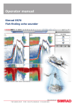
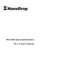
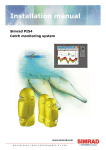
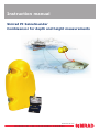
Instruction manual
Simrad PI SeineSounder
Combisensor for depth and height measurements
www.simrad.com
TECHNOLOGY
FOR
SUSTAINABLE
FISHERIES
Simrad PI SeineSounder
Instruction manual
This document gives you the necessary information for
mounting, charging and maintaining the PI SeineSounder
sensor. It also explains how to set up the PI32, PI44 and
PI54 catch monitoring systems to receive and display the
information provided by the sensor.
313700/D
27 June 2008
History
Document number: 313700 / ISBN-10: 82-8066-091-7 / ISBN-13: 978-82-8066-091-6
Rev.A
26 June 2007
Original release.
Rev.B
9 October 2007
Only minor corrections to the text. Table with default
communication channels and update rates modified with new
sensors.
Rev.C
28 February 2008
Document updated to comply with new PI44/54 MMI Software
version 0.47.
Rev.D
26 June 2008
Only minor changes. Table with default communication channels
and update rates modified with new sensors. Document also valid
for PI44/54 MMI Software version 0.50.
Copyright
©2008 Kongsberg Maritime AS
The information contained in this document remains the sole property of Kongsberg Maritime AS. No part
of this document may be copied or reproduced in any form or by any means, and the information contained
within it is not to be communicated to a third party, without the prior written consent of Kongsberg
Maritime AS. The document, or any part of it, may not be translated to any other language without the
written approval from Kongsberg Maritime AS.
Disclaimer
Kongsberg Maritime AS endeavours to ensure that all information in this document is correct and fairly
stated, but does not accept liability for any errors or omissions.
Warning
The equipment to which this manual applies must only be used for the purpose for which it was
designed. Improper use or maintenance may cause damage to the equipment and/or injury to personnel.
The user must be familiar with the contents of the appropriate manuals before attempting to install,
operate or work on the equipment.
Kongsberg Maritime AS disclaims any responsibility for damage or injury caused by improper
installation, use or maintenance of the equipment.
Support
If you require maintenance on your Simrad product contact your local dealer. You can also contact us using
the following address: [email protected]. If you need information about our other products,
visit www.simrad.com. On our web site you will also find a list of our dealers and distributors.
Instruction manual
Table of contents
INTRODUCTION ................................................................ 5
Purpose and applications ..........................................................................................5
Main parts identification...........................................................................................7
Information on the sensor label ................................................................................8
INSTALLATION ................................................................. 9
Mounting on a trawl .................................................................................................9
Mounting on purse seine ........................................................................................ 11
CONFIGURATION ............................................................ 14
Basic configuration.................................................................................................14
Configuration of the PI32 .......................................................................................15
Configuration of the PI44 and PI54 (SW 0.40) ......................................................16
Configuration of the PI44 and PI54 (SW 0.47) ......................................................18
About sensor configuration ....................................................................................20
Default communication channels and update rates......................................... 20
Changing a communication channel ............................................................. 20
Changing the update rate ............................................................................. 21
PI Configurator ........................................................................................... 21
DISPLAY PRESENTATIONS .............................................. 22
Numerical presentation...........................................................................................22
Graphical presentation on PI32 ..............................................................................23
Graphical presentation on PI44 and PI54...............................................................24
CHARGING AND MAINTENANCE ...................................... 27
PI SeineSounder maintenance ................................................................................27
PI SeineSounder charging ......................................................................................28
How to use the Simrad PI Charger .........................................................................28
Daily operation ........................................................................................... 29
Indicators ................................................................................................... 31
Automatic configuration.............................................................................. 31
How to use the Simrad PI MaxiCharger.................................................................32
Daily operation of the PI MaxiCharger ......................................................... 32
PI MaxiCharger indicators........................................................................... 33
313700/D
3
Simrad PI SeineSounder
4
313700/D
Introduction
INTRODUCTION
Efficient fishery with trawl and purse seine assumes professional
and adequate instrumentation on the gear. Simrad has provided
professional instruments for fish finding for more than sixty years.
This user manual describes installation, use and maintenance of
the Simrad PI SeineSounder when put to use with the PI catch
monitoring systems.
Note
The Simrad PI32 and the Simrad PI44 and PI54 systems with
software version 0.40 will only accept PI SeineSounder sensors
with depth range limited to 300 meters. To use 600 or 1000 m
depth range, you will need PI44/54 with software version 0.47
(or later).
Purpose and applications
The purpose of the PI SeineSounder is to achieve accurate
measurements of both the water depth and the height above the
seabed with a single sensor. The PI SeineSounder thus contains
both a pressure sensor to measure the water depth, and an echo
sounder with two transducers to measure the height above the
seabed. The results from these measurements are transmitted
by acoustic signals to the PI catch monitoring system mounted
on the vessel.
The PI SeineSounder has been developed to be used on both
bottom and pelagic trawls and on purse and Danish seiners. The
sensor must be installed in two different ways depending on the
application:
• Trawl: Horizontally behind the headrope
• Seine: Vertically below the footrope
In order to make possible these two applications and mounting
methods, the echo sounder inside the sensor has been equipped
with two transducers. By means of a “sensor key” you can easily
define which transducer to use.
Provided with the sensor is a “gift box” with two sensor keys.
These are two special bolts, and by means of magnetism inside
the bolts, these will select which echo sounder transducer to use.
The bolts will also act as water detectors, and that means that
they will slowly disintegrate. When you mount the sensor on a
trawl or a purse seine, it is therefore important that you use the
correct key:
• Trawl: Use the short bolt
• Purse seine: Use the long bolt
313700/D
5
Simrad PI SeineSounder
Figure 1
A
From its position on the top of the trawl, the sensor measures
the depth from the sea surface
B
The sensor also measures the height above the seabed.
Figure 2
6
The PI SeineSounder in use on a pelagic trawl
The PI SeineSounder in use on a purse seine
A
From its position at the bottom of the purse seine, the sensor
measures the depth from the sea surface
B
The sensor also measures the height above the seabed.
313700/D
Introduction
Main parts identification
Observe the illustration below for identification of the main parts
of the PI SeineSounder.
Figure 3
313700/D
PI SeineSounder
A
Negative charging and fastening lug
B
Positive charging and fastening lug
C
Communication link
D
Location of sensor lamp
E
Sensor “key” and water switch sensor
F
Echo sounder transducer for trawl
G
Echo sounder transducer for purse seine
H
Depth sensor
7
Simrad PI SeineSounder
Information on the sensor label
The sensor label provides the following information.
Figure 4
A
The PI SeineSounder sensor label
Channel identification.
You must write down the two channels currently used by the
sensor to communicate with the PI system.
B
This information identifies the sensor type. Three types are
available:
• PI-ND300: PI SeineSounder for maximum depth 300 m
• PI-ND600: PI SeineSounder for maximum depth 600 m
• PI-ND1000: PI SeineSounder for maximum depth 1000 m
8
C
Spare part order number.
D
Opening for the water to access the pressure sensor.
E
Sensor “key” and water switch sensor
313700/D
Installation
INSTALLATION
The PI SeineSounder has been developed to be used on both
bottom and pelagic trawls and on purse and Danish seiners.
It is important that you understand the two different ways of
installation.
• Trawl: Horizontally behind the headrope
• Seine: Vertically below the footrope
Note
Remove the sensor from the gear before it passes through the
power block.
Ensure that mounting material attached to the charging lugs do
not form an electrical connection, as this will short the charging
current.
Mounting on a trawl
Location
Place the sensor where you wish to monitor the height. This is
normally aft of the headrope at the centre of the net.
Mounting
Secure the two forward fastening lugs (A) using two snap hooks
and rope. Then, secure the two aft fastening lugs (B) using snap
hooks and strong rubber bands. This mounting places the sensor
in a cradle supported on all four sides. In order to secure the
sensor in place, we recommend that you assemble a bag of fine
meshed net, and ties this to the trawl close to the middle of the
headrope. Then, mount the sensor inside this bag. The sensor
must be properly secured to prevent it from moving sideways or
rotate during use. Make sure that you have best possible free
view between the sensor and the bottom, and between the sensor
and the vessel.
313700/D
9
Simrad PI SeineSounder
Figure 5
Mounting on trawl
A
Rope and snap hooks
B
Rubber bands and snap hooks
C
SIMRAD imprint on the sensor must point up!
D
Reverse side of sensor
E
Echo sounder transducer must point towards the bottom!
Note
Ensure that you mount the sensor with the reverse side (D) and
the echo sounder transducer (E) pointing towards the bottom!
The SIMRAD print on the sensor (C) must point up towards the
water surface!
REMEMBER: On trawl, use the short key bolt!
10
313700/D
Installation
Mounting on purse seine
Location
When you mount the sensor on the gear, choose the location
where you wish to monitor depth and height. This is normally
below the footrope. In order to secure a stable communication
with the vessel, and to measure the height, it is very important
that the sensor is allowed to hang freely with the top end pointing
towards the surface during shooting and pursing.
Installation on a purse seine
Attach the sensor to a standard purse ring with two separate
chains (A). Mount one end of each chain to a common snap hook
(B), and secure the hook on the footrope. Mount the other end
of each chain to one of the sensor’s lower lugs using two sturdy
quick links. Mount a safety wire (C) between one of the sensor’s
lower lugs and anywhere on the net except on the footrope. Make
sure that security line does not prevent the sensor from hanging
freely!
Note
You must make sure that the sensor is mounted vertically with
its rear end pointing towards the seabed. Unless the top end
of the sensor points towards the surface, you may loose the
communication link.
REMEMBER: On purse seine, use the long key bolt!
313700/D
11
Simrad PI SeineSounder
Figure 6
12
Installation on a purse seine
A
Two chains. One end of each chain is mounted on a common
snap hook, while the other end of each chain is secured to
one of the sensor’s lower lugs using a sturdy quick link.
Make sure that the chains are not too long!
B
Large snap hook
C
Safety line with “C” links at the upper end (D) and a sturdy
quick link on the sensor’s lower lug.
D
The “C” link can be mounted several places, but NOT on
the footrope.
313700/D
Installation
Installation on a tuna purse
The sensor must not be attached to the footrope wire, but to the
footrope chain. Use a safety wire in addition in case the sensor is
ripped off the net.
Figure 7
313700/D
Installation on a tuna purse
13
Simrad PI SeineSounder
CONFIGURATION
In order to allow the information from the PI SeineSounder
sensor to be accepted and understood by the PI catch monitoring
system, the PI receiver must be set up correctly. This means that
you must tell the receiver that the sensor exists by entering the
sensor type, communication channels and update rate. For more
detailed information about the settings and parameters, refer to
the relevant operator and/or reference manuals.
Note
The PI SeineSounder sensor is a “dual” sensor. This means that
it will occupy two channels on your PI system!
Upon delivery, all PI SeineSounder sensors are set up with
factory default channels and update rates. Refer to the table in
section About sensor configuration on page 20.
Note
The sensor and the PI system setup must correspond, otherwise
the communication will not work. To change the sensor setup
(channel selection and update rate), use the PI Configurator
utility. See PI Configurator on page 21.
Basic configuration
Observe the following basic settings:
• When you put the PI SeineSounder to use, you must set it
up with one unique sensor number with two measurements.
Only one update rate can be chosen, this is common for both
measurements. The channel numbers are defined individually
for the two measurements. Both the update rate and the
channel numbers must be chosen according to the sensor’s
configuration. Write down this configuration for future
reference. For default settings, refer to the table in section
About sensor configuration on page 20.
• On the receiver, the Interference filter must be switched
on. Set it to Level 9 if you have noise problems from other
hydroacoustic sources. Note that this filters will influence the
signal spectrum shown in the Status display.
• We recommend that you set the Sensor filter to Light.
14
313700/D
Configuration
Configuration of the PI32
This procedure explains how to set up the PI32 catch monitoring
system to access the information provided by the PI SeineSounder
sensor. For more detailed information about the PI32 settings and
parameters, refer to the PI32 Operator manual.
The PI32 will only accept PI SeineSounder sensors set up for
maximum 300 meters depth.
Note
In order to set up the PI system you must know what kind of
sensors you have, which communication channels they use, and
how often they communicate (the update rate). You need this
information before you start the setup process.
Do not carry out sensor setup unless absolutely necessary.
We recommend that you use the form at the beginning of the
PI32 Operator manual to write down the sensors you have and
their respective communication channels and update rates.
Figure 8
PI SeineSounder setup example, PI32
This example shows how the PI32 is set up to receive information
from the PI SeineSounder sensor. Standard communication
channels and update rates are used.
How to access the Sensor Setup menu
1
2
3
Press the MENU button to open the main menu.
On the Setup menu, select Sensor setup.
Press the ENT button to allow for changes, and then the
same button one more time to accept the warning.
• You must now use the circular navigation button to
move the cursor between the parameters, and the + and
- buttons to select values.
How to set up depth readings on PI32
1
2
3
4
313700/D
Choose an available sensor; 1, 2 or 3.
Define the sensor type (by default None) to Single.
Set Update to the correct update rate.
Set Measure to the chosen sensor type Spread.
15
Simrad PI SeineSounder
Note
If you have an older software version on your PI32, you
must select sensor type “Spread” even though you are going
to read depth information from the PI SeineSounder sensor.
5
Set the communication Channel to its correct value.
How to set up height readings on PI32
1
Choose an available sensor; 1, 2 or 3.
2
Define the sensor type (by default None) to Single.
3
Set Update to the correct update rate.
4
Set Measure to the chosen sensor type Height.
5
Set the communication Channel to its correct value.
Configuration of the PI44 and PI54 (SW 0.40)
This procedure explains how to set up the PI44 and PI54 catch
monitoring systems to access the information provided by the
PI SeineSounder sensor. For more detailed information about
the settings and parameters, refer to the relevant operator and/or
reference manual(s).
Note that this PI44 and PI54 software version will only accept PI
SeineSounder sensors set up for maximum 300 meters depth.
Note
This procedure is only applicable if you have installed MMI
software 0.40 on your PI44/54 Operating Unit. To find out, open
the Status Display.
We recommend that you use the form at the beginning of the
PI44 or PI54 operator and/or reference manual to write down the
sensors you have and their respective communication channels
and update rates.
Note
In order to set up the PI system you must know what kind of
sensors you have, which communication channels they use, and
how often they communicate (the update rate). You need this
information before you start the setup process.
Do not carry out sensor setup unless absolutely necessary.
16
313700/D
Configuration
Figure 9
PI SeineSounder setup example, PI44/PI54 SW 0.40
This example shows how the PI44 (or PI54) running MMI
software version 0.40 is set up to receive information from a PI
SeineSounder sensor. Standard communication channels and
update rates are used.
How to access the Setup menu
1
Press the MENU button to open the main menu.
2
On the Setup menu, select Sensor setup.
3
Press the ENT button to allow for changes, and then the
same button one more time to accept the warning.
How to set up the depth readings
1
Choose an available sensor; 1 to 6.
2
Define the sensor type (by default None) to Single.
3
Set Update to the correct update rate.
4
Set Measure to the chosen sensor type Spread.
Note
If you have the MMI SW 0.40 software version on your
PI44 or PI54 Operator Unit, you must select sensor
type “Spread” even though you are going to read depth
information from the PI SeineSounder sensor
5
313700/D
Set the communication Channel to its correct value.
17
Simrad PI SeineSounder
How to set up height readings
1
Choose an available sensor; 1 to 6.
2
Define the sensor type (by default None) to Single.
3
Set Update to the correct update rate.
4
Set Measure to the chosen sensor type Height.
5
Set the communication Channel to its correct value.
Configuration of the PI44 and PI54 (SW 0.47)
This procedure explains how to set up the PI44 and PI54 catch
monitoring systems to access the information provided by the
PI SeineSounder sensor. For more detailed information about
the settings and parameters, refer to the relevant operator and/or
reference manual(s).
Note
This procedure is only applicable if you have installed MMI
software 0.47 or later on your PI44/54 Operating Unit. To find
out, open the Status Display.
We recommend that you use the form at the beginning of the
PI44 or PI54 operator and/or reference manual to write down the
sensors you have and their respective communication channels
and update rates.
Note
In order to set up the PI system you must know what kind of
sensors you have, which communication channels they use, and
how often they communicate (the update rate). You need this
information before you start the setup process.
Do not carry out sensor setup unless absolutely necessary.
18
313700/D
Configuration
Figure 10
(or later)
PI SeineSounder setup example, PI44/PI54 SW 0.47
This example shows how the PI44 (or PI54) running MMI
software version 0.47 or later is set up to receive information
from a PI SeineSounder sensor. Standard communication
channels and update rates are used.
How to access the Setup menu
1
Press the MENU button to open the main menu.
2
On the Setup menu, select Sensor setup.
3
Press the ENT button to allow for changes, and then the
same button one more time to accept the warning.
How to set up the depth and height readings
313700/D
1
To reset the unit, set all six sensors to default sensor type
None.
2
Choose the sensor input you wish to use for the PI
SeineSounder; 1 to 6.
3
Define the sensor type (by default None) to Dual.
4
Set Update to the correct update rate.
5
Set Measure 1 to the chosen sensor type Depth 300M, Depth
600M or Depth 1000M depending on the depth rating on
your PI SeineSounder.
6
Set the communication Channel to its correct value.
7
Set Measure 2 to the chosen sensor type Height.
8
Set the communication Channel to its correct value.
9
Press the ENT button to save the changes and exit.
19
Simrad PI SeineSounder
About sensor configuration
All sensors are provided from Simrad with predefined
communication channels and update rates.
Default communication channels and
update rates
See the table below for the initial values for the communication
channels and update rates for the various sensors.
Table 1
Default communication channels and update rates
Sensor
PI Bottom Contact
PI Catch
PI Depth
PI Height
PI Remote/Depth
PI Spread
PI Spread/Depth
PI Twin Spread
PI Temperature
PI Geometry
PI SeineSounder
Com.channel(s)
6
4
Depth 300M: 16
Depth 600M: 12
Depth 1000M: 10
14
Depth 300M: 11
Depth 600M: 15
Depth 1000M: 13
2
Depth 300M: 16
Depth 600M: 12
Depth 1000M: 10
Spread: 2
2 and 7
8
1 and 5
Depth 300M: 5
Depth 600M: 9
Depth 1000M: 1
Height: 14
Update rate
Normal
Normal
Fast
Fast
Fast
Fast
Fast
Fast
Fast
Fast
Fast
Changing a communication channel
It may be required to change one or more communication
channels, and there may be many reasons for this.
• You have more than one of each sensor. For example, if you
have three temperature sensors, they MUST communicate
on three different channels.
• Other vessels near your use the same PI catch monitoring
system (or a similar), and they have one or more of their
sensors set up to the same communication channels as you
have. This will create interference, as you will "read" each
others sensors.
20
313700/D
Configuration
• If your sensors are set up to use communication channels too
close to each other (for example, you have chosen channels 4,
5 and 6), this will limit the vessel’s speed. The reason for this
is the Doppler effect. If the speed is too high, the Doppler will
cause the transmission frequencies to change so much that
they overlap, and this will create interference. The PI catch
monitoring system will provide a warning if this is about to
happen! You must then either change to other communication
channels further apart, or reduce the maximum shooting speed.
• If you operate at the maximum range of the sensors, you
may be able to increase this range slightly if you use
lower communication channels. This is because the lower
communication channels use lower transmission frequencies.
All sensors are provided from Simrad with a default
communication channel. In some cases you may find that the
chosen channel does not suit your operational needs, for example
if you have more than one sensor of any given type. This is a
decision you have to make depending on how many sensors you
use, and how many of these that are identical.
Changing the update rate
It may be required to change the update rate on a sensor, that is
how often it sends information back to the PI catch monitoring
system. A high update rate will give frequent information
updates, but the sensor will use more battery power. If you need
your batteries to last as long as possible, you must consider
lowering the update rate.
• A low update rate will provide you with fewer information
updates, but the battery will last very long.
• A high update rate will give you frequent information updates,
but the battery will run out faster.
All sensors are provided from Simrad with a default update rate
setting. In some cases you may find that this update rate does not
suit your operational needs. This is a decision you have to make
depending on the local fishing conditions.
PI Configurator
Simrad has developed a dedicated computer utility to change
the sensor configurations. By means of an ordinary desktop
computer and a few special cables you can do this job yourself. If
you do not require frequent configurations, you can also contact
you local dealer for assistance. Contact the dealer for more
information.
313700/D
21
Simrad PI SeineSounder
DISPLAY PRESENTATIONS
The information provided by the PI SeineSounder sensor is
shown on the PI catch monitoring system’s colour display. Two
presentations are available:
• Numerical presentation
• Graphical presentation with or without echogram
Numerical presentation
The numerical presentation of the PI SeineSounder data is
automatically shown in the relevant display modes. Since this is
a “dual” sensor two rectangles are used.
Figure 11
Numerical presentation, example
A
Sensor identification
B
Unit of measurement
C
Depth
D
Depth change/minute
E
Arrow indicates that the depth is increasing
F
Visual alarm
G
Sensor transmission indicator
H
Interference warning
I
Height
J
Height change/minute
K
Arrows pointing “out” means that the height is increasing,
arrows pointing “in” means that height is decreasing
On the PI display, you must use two channels to receive the
information from the PI SeineSounder. The depth and height
values are then shown in the numeric display. If the height or
depth is increasing or decreasing, this is shown with two arrows
22
313700/D
Display presentations
and the variation in meters per minute. You can also see the
depth and height changes as a function of time in a graphical
presentation.
When the readings are stable, the digits are shown in black
colour. If the contact is lost, the characters *** are shown in grey.
If the height is out of range, the display shows: ???.
Graphical presentation on PI32
This section contains a procedure to explain how you can set
up the PI32 to show you a graphical presentation of the PI
SeineSounder data providing depth- and height markers.
Figure 12
Graphical presentation on PI32
The purpose of the depth- and height markers on the graphical
presentation is to keep an eye on how deep and how high above
the seabed the gear is situated. The height sensor in the PI
SeineSounder measures the distance from the seabed and up to
the sensor, while the depth sensor measures the distance from the
sea surface and down.
1
Identify the sensor you wish to use, and make sure that the
sensor is connected to the PI32 with correct communication
channels and update rates.
2
Ensure that you have a graphical presentation active on your
PI unit.
3
Press theENT button to open the Graphic setup menu.
• The Marker line parameter allows you to switch the
marker lines on or off for sensors S1, S2 and S3.
313700/D
23
Simrad PI SeineSounder
4
Use the Marker line parameter to switch the requested
marker line(s) On.
5
Enter the requested values for the marker line Marker line
thickness and Marker line delay.
• Marker line thickness: Use this parameter to control the
thickness (in pixels) of the marker line(s).
• Marker line delay: The echo sounder information is
provided by the transducer located below the vessel’s
hull. The sensor is however located on the gear, and may
be position several hundred meters behind the vessel. In
order to compensate for this physical distance you can
add the Marker line delay. You must calculate this delay
based on the vessel’s speed, the distance from the aft
stern to the gear, and the current depth of the gear.
6
Press the ENT button to save the chosen parameters and
return to the graphical presentation.
The depth- and height marker lines are shown in the graphical
presentation using solid lines and the same colours as the
background in the numerical presentation. In order to read the
accurate depth you can observe the depth scale on the right hand
side, or read the value in the numerical presentation.
Graphical presentation on PI44 and PI54
This section contains a procedure to explain how you can set up
the PI44 and PI54 to show you a graphical presentation of the PI
SeineSounder data providing depth- and height markers.
24
313700/D
Display presentations
Figure 13
Graphical presentation on PI44/PI54
The purpose of the depth- and height markers on the graphical
presentation is to keep an eye on how deep and how high above
the seabed the gear is situated. The height sensor in the PI
SeineSounder measures the distance from the seabed and up to
the sensor, while the depth sensor measures the distance from the
sea surface and down.
1 Identify the sensor you wish to use, and make sure that
the sensor is connected to the PI system with correct
communication channels and update rates.
2 Ensure that you have a graphical presentation active on your
PI system.
3 Press the ADJ button to open the Graphic setup menu.
4 Press the GAIN+ button repeatedly to reach the Marker line
dialogue.
5 Observe the list of sensors that appear. Only those sensors
that can provide a marker line are listed.
6 For every sensor (depth and height) that are used, set Auto
to On.
• This allows the PI unit to use the Trawl Calculator to
estimate the correct time delay. (This is not applicable
for purse seiners.)
• If you wish to calculate the delay yourself, set Auto to
Off. You must then enter the calculated value into the
Delay column.
7 Enter requested value for Width.
313700/D
25
Simrad PI SeineSounder
• Use this parameter to control the thickness (in pixels)
of the marker line(s).
8
For every marker line, set Show to On.
9
If you wish to see the marker lines in the expanded views
(bottom expansion, zoom and phased range), set Sensor
marker in expansion to On.
10 If you wish the PI system to draw a thin white line over and
under the marker lines, sett Marker white zone to On.
11 If you wish to see the height marker only in expanded views,
set Height marker in main echogram to Off..
12 Select requested Height reference. You have three
alternatives:
1
On a purse seine, you can set up the system to show
you the actual difference between the depth and height
values. These should never be 0, because that would
mean that the footrope is touching the bottom. To
monitor this, set Height reference to Depth.
2
The height sensor measures the distance from the
headrope to the bottom. If you use the echo sounder
in the PI system, set Height reference to Bottom, and
the height marker will follow the bottom contour. With
correct time delay you will then see the trawl in “true
motion”.
3
If you can not use the PI echo sounder, set Height
reference to Surface. The height is now shown using 0
m depth as reference. The distance from the 0 meter
line and down to the marker line is then the current
height of the gear.
13 Press the ENT button to save the chosen parameters and
return to the graphical presentation.
26
313700/D
Charging and maintenance
CHARGING AND MAINTENANCE
This chapter explains how you shall recharge the battery in the PI
SeineSounder sensor, and how you shall best maintain the sensor.
PI SeineSounder maintenance
Once installed and put to use, the sensor will automatically be
switched on once the water switch is activated. After an initial
start-up, the sensor starts transmission of the measured data it
collects.
When the sensor is not in use, check that the sensor lamp is not
flashing, as this indicates that the sensor is active and discharging
its batteries. In this case, wash the sensor in fresh water.
All sensors are equipped with a water switch, and two different
types are used. If your sensor is equipped with a sacrificial brass
screw, observe the following procedure for replacement.
1
Turn the sensor upside down, and locate the brass screw.
2
Inspect the screw for wear and tear.
3
If replacement is required, locate a new screw.
Before a new screw is inserted, Aqua Shield (or a similar
underwater lubricant) must be applied. Due to the size of
the tube, we recommend that the grease is applied from
a syringe.
4
Apply Aqua Shield to the screw threads.
5
Insert the screw, mount firmly, but not too hard. Use
maximum torque 1.5 NM
A pack with ten screws and a tube of Aqua Shield can be
ordered from Simrad as a spare parts kit.
Aqua Shield is manufactured by D.A.Stuart, Warrenville,
Illinois, USA.
Visit www.d-a-stuart.com.
No other maintenance of the sensor is required.
Note
You must never attempt to open the sensor. There are no user
serviceable parts inside, and you may easily cause a leak.
313700/D
27
Simrad PI SeineSounder
PI SeineSounder charging
The PI SeineSounder sensor must be charged between operation.
The battery lifetime depends on the update rate you have chosen.
Note
To charge the PI SeineSounder sensor, use the Simrad PI Charger
or the Simrad PI MaxiCharger.
Table 2
Battery lifetime for the PI SeineSounder sensor
Update rate
Approximate lifetime between charging
Fast
24 hours
Normal
60 hours
Slow
80 hours
Optimal sensor charging temperature is from +10 to +25° C.
Note
Charging sensors at sub zero temperatures can create explosive
gasses. Kongsberg Maritime AS assumes no liability for
improper charging of sensors, or the use of chargers not specified
in our sensor or charger documentation.
How to use the Simrad PI Charger
The Simrad PI Charger is an intelligent battery charger for fast
and secure charging of all PS and PI sensors. The charger will
automatically set up the correct charging current depending on
the sensor type and the battery temperature. A “fuel meter”
shows the status of the battery during the charge.
28
313700/D
Charging and maintenance
Figure 14
The PI Charger set up to charge a PI sensor
Even though the PI Charger is designed for fast charging of the
PI sensors, it can also charge the PS sensors, but only at normal
charge rate.
Daily operation
Observe the following procedure for daily operation.
1 Attach the charging clamps to the sensor as follows:
• Red clamp: Positive (+) fastening lug
• Black clamp: Negative (–) fastening lug
• On every sensor the polarity of the fastening lugs are
engraved on the sensor body using + and – characters.
2 Ensure that mounting materials do not short circuit the
charging lugs.
• This may be ropes, wires, chains or other items that
obstruct or short circuit the electrical connections.
3 When the charger is connected to the sensor, check the
charger lamps.
• Once connected, the charger will identify whether the
sensor connected can be fast charged or not. This is
shown by the yellow lamps. If the top lamp flashes
rapidly, the sensor is fast charged.
313700/D
29
Simrad PI SeineSounder
4
• If your sensor can be fast charged, the charger will
also check the internal temperature of the sensor. The
temperature is shown on the “thermometer” on the
charger’s front panel. If you charge a sensor that can not
be fast charged, this “thermometer” does not work.
Observe the charge times and temperature limitations!
• Fast charge: The PI Charger will first recharge the
sensor battery for approximately one hour to reach 70%
battery capacity, then approximately three hours to reach
100% capacity. Once fully charged, a constant trickle
charge will compensate for self discharging.
Note
Fast charging only applies to PI sensors!
• Normal charge: The PI Charger will first recharge the
sensor battery for 16 hours for full battery capacity. This
mode applies for charging PI sensors outside specified
temperature range, and for all PS sensors.
• Charging must only take place within the specified
temperature range. For best results, keep the ambient
temperature between +10 and +25°C.
Note
Do not charge sensors in temperatures above +50°C or
below 0°C!
WARNING
Charging a sensor at sub zero temperature might
develop explosive gases representing a potential
danger. Simrad assumes no liability for improper
charging, or the use of other chargers than those
approved by us.
30
313700/D
Charging and maintenance
Indicators
A
+12 to 32 Vdc connected
B
“Fuel meter”, the number of LEDs illuminated shows the
current charging status.
A complete charging cycle is indicated with all “full”
battery. Charging is indicated as follows:
• Fast flashing: Fast charging in progress
• Slow flashing: Normal charging in progress
• On/off every four seconds: Trickle charging in progress
C
Battery temperature indicators during fast charging of PI
sensors:
• Green: Battery temperature between +5 and +40°C. Fast
charge is enabled.
• Green and Blue: Battery temperature between 0 and
+5°C. Fast charge is disabled, normal charge is used.
• Green and Red: Battery temperature between +40 and
+50°C. Fast charge disabled, normal charge is used.
• Blue: Battery temperature is below 0°C. No charging
takes place.
• Red: Battery temperature is above +50°C. No charging
takes place.
Automatic configuration
The charger communicates with the sensor at regular intervals.
The fast charge cycle is controlled by data exchanged between
the PI sensor and the charger, and a series of safety mechanisms
controls the termination of the fast charging current.
The PS sensors do not communicate with the charger. A constant
charge current of 58 mA is then set up by the charger regardless
of the battery temperature.
313700/D
31
Simrad PI SeineSounder
How to use the Simrad PI MaxiCharger
The Simrad PI MaxiCharger is a plain battery charger to be used
with large PI sensors. These are:
• PI Spread
• PI Height
• PI SeineSounder
• PI Spread/Depth
• PI Remote/Depth
• PI Geometry
WARNING
Do not use the PI MaxiCharger on any other PI
or PS sensors than those listed here! The large
charging current may damage the battery!
Figure 15
Simrad PI MaxiCharger
The Simrad PI MaxiCharger is provided with a small booklet
from the manufacturer (Mascot). Read this booklet before you
put the charger to work!
WARNING
Charging a sensor at sub zero temperature might
develop explosive gases representing a potential
danger. Simrad assumes no liability for improper
charging, or the use of other chargers than those
approved by us.
Daily operation of the PI MaxiCharger
Observe the following procedure for daily operation.
1 Connect the charger to 230 Vac, and check that the charger
lamp is lit in yellow.
32
313700/D
Charging and maintenance
2
Ensure that mounting materials do not short circuit the
charging lugs.
• This may be ropes, wires, chains or other items that
obstruct or short circuit the electrical connections.
3
Attach the charging clamps to the sensor as follows:
• Red clamp: Positive (+) fastening lug
• Black clamp: Negative (–) fastening lug
• On every sensor the polarity of the fastening lugs are
engraved on the sensor body using + and – characters.
4
When the charger is connected to the sensor, check the
charger lamps.
• After a few seconds, the lamp on the charger will change
from yellow to orange/red. This means that fast charging
is in progress.
• When the battery in the sensor has reached 90% capacity
the lamp will change from orange/red to green with
short yellow flashes. This means that top charging is in
progress.
• When the battery is fully charged, the lamp turns green.
Trickle charging is now active. You can safely allow
trickle charging for long periods of time.
PI MaxiCharger indicators
The charger is only equipped with a single indicator lamp, this
lamp will however change colour to show the status of the
charging process.
• Yellow: The charger is connected to 230 Vac, it has not been
connected to the sensor, and it is ready for use.
• Orange/Red: The charger is connected to a sensor, and fast
charging is in progress.
• Green with short yellow flashes: Top charging is in progress.
• Green: Trickle charging is in progress.
313700/D
33
Simrad PI SeineSounder
A
trawl, 9
Applications, 5
N
B
Bolt
LONG for purse seine, 5
SHORT for trawl, 5
C
Charging, 27–28
Communication
channel
default values, 20
why change?, 20
Configuration, 14
PI32, 15
PI44
SW 0.40, 16
PI54
SW 0.40, 16
sensor, 20
D
Default
communication
channels, 20
update rate, 20
Display presentation
graphical
PI32, 23
PI44/PI54, 24
numerical, 22
Display presentations, 22
Numerical
presentation, 22
P
PI Charger
use, 28
PI MaxiCharger
use, 32
PI32
configuration, 15
PI44
configuration
SW 0.40, 16
PI54
configuration
SW 0.40, 16
Presentations, 22
Procedure
configuration
PI32, 15
PI44 SW 0.40, 16
PI54 SW 0.40, 16
Purpose, 5
Purse seine
sensor mounting, 11
S
Sensor
configuration, 20
Sensor key
LONG for purse seine, 5
SHORT for trawl, 5
G
Graphical
display presentation
PI32, 23
PI44/PI54, 24
I
Installation, 9
purse seine, 11
trawl, 9
Introduction, 5
T
Trawl
sensor mounting, 9
U
Update rate
default values, 20
why change?, 21
W
M
Water detector, 5
Maintenance, 27
Mounting
purse seine, 11
34
313700/D
Index
313700/D
35
ISBN-10: 82-8066-091-7
ISBN-13: 978-82-8066-091-6
©2008
Kongsberg Maritime AS