1
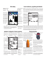
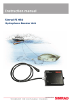
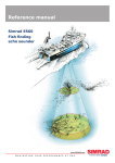
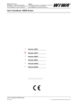
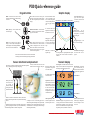
PI30 Quick reference guide
Keypad buttons
Graphic display
MENU - turns the menu on and off. Press
to hide the displayed menu without making
a selection.
ENT - turns the cursor on and off, opens
parameters for the insertion and confirms
data. Select setup directly from the chosen
display.
D1 to D3 - identifies which
sensor corresponds to the
data window (background
colour) and subsequent bar
and line graph information.
Minus (-) Plus (+) - selects available values,
scales and ranges.
Multi-direction button - controls the cursor’s location in activated menus and displays, moves the VRM.
m - indicates that sensor
depth is shown in meters or
the sinkrate is in m/min.
PWR - turns on the unit, press until the
display is visible. Adjusts LCD brightness,
contrast, display colour and keypad illumination. Press twice to turn off the unit.
WIN - changes between one of the four
selected windows. Press when the desired
window is displayed to select. Press and
hold for more than two seconds to actuate
automatic window rotation, press again to
return to normal operation.
Time scale - is selected in
Graphic setup.
Sensor attachment and placement
Sensor(s) attached near the surface will
indicate if the net submerges when purs-
Data window 2
Data window 3
Depth scale - can be
decreased or increased using
the respective - or + buttons
on the keypad.
Line graph - provides a
depth and sinkrate profile
for the net. Line thickness
is selected in the Graphic
setup.
Refer to the PI30 Instruction manual for more information
concerning echo sounder and navigation keypad functions.
PS30 sensors are preferably attached to the net’s bridle and suspended
freely so that they point vertically when pursing.
Data window 1
Bar graph - displays a “side
view” of the net’s depth.
An echogram may be superimposed on the Graphic
display when an echo sounder transducer is
installed.
(857-164315A / AA000 /37-26)
D3
Which ever method of attachment is chosen, PS30 sensors
must be protected against unnecessary shock when shooting
the net.
Information from the sensors (D1, D2 and D3) is displayed in
the corresponding data windows (1, 2 and 3) with differently
coloured backgrounds to facilitate interpretation.
D2
D1
A complete overview of the fishing operation is
achieved using three PS 30 depth sensors, permanently
labelled D1, D2 or D3 and attached to the purse seine
as illustrated above. Once deployed, the sensors begin
transmitting automatically.
Alarm limits - both the upper
and lower limits are displayed.
Numeric display
D1 to D3 - indicates which
depth sensor corresponds
to the data window.
Sensor depth - is rounded to the nearest meter for
depths over 100 m, otherwise it is displayed to one
decimal place. Maximum depth is 290 m.
m - indicates that the depth
is shown in meters.
When purse seining
for tuna, PS30 sensors
should
be
attached to the net’s
footrope (refer to the
Instruction manual).
Sensor information - displays actual sensor depth
or sinkrate (selected in the
Graphic setup).
Data window 1
Graphic alarm - the arrows’
direction indicates if the net
depth should be increased
or decreased with regard to
the selected alarm limits.
Graphic alarms may be
accompanied with or without audible alarms.
Yellow pulse lamp - blinks
each time a signal is received
from the respective sensor.
Rise/sink rate - is displayed
in the selected units per
minute. Values near 0 indicate
that the net has stopped sinking.
Data window 2
Data window 3
Interference signal - displayed when nearby
vessel(s) operate on the same channel or with other
hydroacoustic equipment. Contact your Simrad
dealer to select a different sensor frequency should
this problem persist (see MP filter on side two).
WORLDWIDE MANUFACTURER OF MARINE ELECTRONICS
Arrows - indicate if the net is
either rising or sinking. Here
the net is sinking at a rate of
12 m/min.
Sensor maintenance, programming and calibration
Status display
Hydrophone cable information:
- Black = break
- Red = short circuit
- Yellow = OK
Data window 1
Data window 2
Data window 3
The Status display shows
sensor data, signal thresholds and background noise
levels providing an overview
of present hydro-acoustical
conditions and the margin
for reliable signal detection.
Other information displayed
includes cable status, program version, and echo
sounder / position information if the necessary equipment is connected.
Data window information:
-Sensor depth
-Sensor identification
-Units of depth
-Pulse lamp condition
SW - software version
E - error message
CH/R - channel
The red field shows the
signal level that is over the
detection threshold, DT.
The green field over the
noise reference level shows
the detection threshold, DT.
Average noise reference
levels.
Frequency spectrum - for frequencies on the 00 - 15 band. Select the desired
band by pressing the respective - or + buttons on the keypad (wait for the
unit to update the display). The graph represents background noise and
signal strength of the frequency band selected.
Information from an interfaced GPS or integrated echo
sounder if the unit is connected to a transducer.
Installation / Configuration / Receiver parameters
Defines sensors 1 to 3
and keeps track of their
attachment locations to
the net.
Select the channel shown on the sensors’ labels
and/or the visual LED identification signal displayed when turned on. Note the sensor configuration for later reference.
AGC - recommended to
be ON. Under favorable
noise conditions manual
gain adjustment may
provide
increased
range.
MP filter - reduces
excessive echo return or
interference from other
hydro-acoustic equipment operating on the
configured
channel
where the sensor is not
in use.
Max shooting speed - compensation
for doppler shift when shooting the
net. Maximum speed may be limited by
channel separation. Effective only when
the vessel is in motion.
MPF level - is activated
when the MP Filter is ON.
Reduce the MPF level value
in small steps to increase the
filter ’s effectiveness. Avoid
reducing the level so low that
the sensors’ signals are also
blocked.
Detection threshold
increases the DT if false signals are detected on a channel where a sensor is in use.
A high DT indicates that
only the strongest signals
will be received. A low DT
may provided a longer range
under favorable conditions.
The PI30 must receive at least four
pins when first powered up to generate data. Should one or two pings be
missing, the predicted value will be
displayed in grey. If the signal is lost,
*.* is displayed.
Sensor filter:
- OFF = no effect (fastest
update of data)
- Light = average of the
last four pings
- Heavy = average of the
last eight pings
Maintenance - rinse sensors with fresh water to avoid depleting their batteries after use. A saltwater film on the
exterior of a sensor can complete the circuit from the sea water detector to a fastening lug. This phenomenon
may also cause the red LED on the sensor charger not to illuminate when a sensor’s battery is deeply depleted.
To remedy this problem, wash the sensor with fresh water and wait several minutes. The sensor may then be
charged as described under “Charging”.
Programming - of sensors
is accomplished using a PC
connected to their charging/
fastening lugs. To program
a sensor both the software,
Simrad number: 889-24037
and a special cable number:
380-204728 are required. The
dealer is normally responsible for programming the
various channel selections
and other functions.
Other depths - if the sensor
is programmed to start at a
depth of 2 m, it should be
suspended at 3 m during the
calibration procedure. Calibrate the sensor as described
and note the offset values.
Reduce the offset values by
2 m after calibration.
Calibration - is performed on board the vessel to set the sensors’ reference levels to one meter as follows: Suspend
the sensors over the side of the vessel individually or together at a depth of one meter, the draft plus one meter or the
reference level that is to be defined as one meter. Once the sensors’ depth readings have stabilised, set the Calibration
parameter to YES. Sensor calibration takes one minute and the data will be temporarily displayed as grey during this
time. Once the process is complete, the data will again be displayed in black with updated offset values and a depth
of one meter. Note: Sensors not submerged in saltwater will not be calibrated.
Charging and testing
A fully depleted sensor (representing about 30 hours
of continuous service) must be charged for at least 16
hours to restore its battery to full capacity. Optimal
charging temperature is from +10ºC to 25ºC. Never
charge sensors at temperatures below freezing.
Sensor 1, 2 or 3
Channel 1 to 30
Warning! The use of chargers not specified by Simrad
may lead to personal injury and/or material damage.
Positive charging/
fastening lug (+)
Negative charging/
fastening lug (-)
Sea water
detector
(serial no 300
and above)
Charging - connect the red and black alligator clamps
to the positive and negative fastening lugs labelled “+”
and “-” respectively. Check that the charging lamp on
the sensor charger is illuminated and that the sensor
being charged blinks every four seconds. If it does
not blink in this manner (indicating charging mode),
the battery will not be fully charged. Note: Never
charge a sensor with wet rope in contact with the
fastening lugs.
Testing - touch the sea water detector (serial no below
300: touch the cover) and a fastening lug at the same time.
This will cause the sensor to switch ON and identify the
channel it transmits on with a series of blinks (see the
Instruction manual) and begin sending data if it is not
programmed differently.
• If the sensor does not blink when switched ON, it
indicates a depleted battery and should be charged for
a few minutes and tested again. If it blinks and begins to
send data, it should be charged for at least 16 hours.
• If the sensor continues to just blink when switched ON
it indicates a close to empty battery. Charge the sensor for
10 minutes and test. If it resume normal operation, charge
for ~ 16 hours.
• If the sensor repeats the start up blinking sequence with
a four seconds interval, it indicates fault with the depth
cover. Contact your nearest Simrad dealer.