1
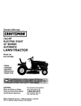
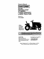
Owner's Manual
20.0 HP
ELECTRIC
START
42" MOWER
6 SPEED TRANSAXLE
LAWN TRACTOR
Model No.
917.272430
•
•
•
•
Safety
Assembly
Operation
Maintenance
• Repair Parts
CAUTION:
Read and follow all
Safety Rules and instructions
before operating this equipment.
For answers to your questions
about this product, Call:
1-800-659-5917
Sears Craftsman Help Line
5 am - 5 pro, Mort - Sat
Sears, Roebuck and Co., Hoffman Estates, IL 60179
visit our Craftsman website: www.sears.com/craftsman
Warranty ...............................................
Safety Rules .........................................
Product Specifications ..........................
Assembly ..............................................
OperaUon ............................................
Maintenance Schedule ......................
Maintenance ....................................... 19
Service and Adjustments .................... 23
Storage ............................................... 29
Troubleshooting .................................. 30
Repair Parts ........................................ 34
Parts Ordering ..................... Back Cover
2
3
6
6
12
19
LIMITED TWO YEAR WARRANTY ON CRAFTSMAN RIDING EQUIPMENT PARTS
For two (2) years from the date of purchase, if this Craftsman Riding Equipment is
maintained, lubdcated and tuned up according to the instructions in the owner's
manual, Sears will repair or replace, free of charge, any parts found to be defective in
material or workmanship. Warranty service is available free of charge by returning
your Craftsmen riding equipment to your nearest Sears Service Center. In-home
warranty service is available but a trip charge will apply. This warranty applies only
while this product is in the United States.
This Warranty does not cover:
• Expendable items which become worn dudng normal use, such as blades, spark
plugs, air cleaners, belts and oil filters.
• Tire replacement or repair caused by punctures from outside objects, such as nails,
thorns, stumps, or glass.
• Repairs necessary because of operator abuse, including but not limited to, damage
caused by towing objects beyond the capability of the riding equipment, impacting
objects that bend the frame or crankshaft, or over speeding the engine.
• Repairs necessary because of operator negligence, including but not limited to,
electdcal and mechanical damage caused by improper storage, failure to use the
proper grade and amount of engine oil, failure to keep the deck clear of flammable
debds, or the failure to maintain the equipment according to the instructions
contained in the owner's manual.
• Engine (fuel system) cleaning or repairs caused by fuel determined to be contaminated or oxidized (stale). In general, fuel should be used within thirty (30) days of its
purchase date.
• Riding equipment used for commercial or rental purposes. A product is "used for
commercial purpose" if is used for any purpose other than single family household
dwellings or in usage where profit is made.
LIMITED 90 DAY WARRANTY ON BATTERY
For ninety (90) days from date of purchase, if any battery included with this dding
equipment proves defective in matedal or workmanship and our testing deterlmines
the battery will not hold a charge, Sears will replace the battery at no charge. Warranty service is available free of charge by returning your Craftsman dding equipment
to your nearest Sears Service Center. In-home warranty service is available but a tdp
charge will apply. This warranty applies only while this product is in the United States.
TO LOCATE THE NEAREST SEARS SERVICE CENTER OR TO SCHEDULE INHOME WARRANTY SERVICE, SIMPLY CONTACT SEARS AT 1-800_-MY-HOME
This Warranty gives you specific legal dghts, and you may also have other dghts
which may vary from state to state.
Sears, Roebuck and Co., D/817 WA, Hoffman Estates, IL 60179
2
IMPORTANT: This cutting machine is capable of amputating hands and feet and
throwing ob ects. Failure to observe the following safety instructions could result in
sadous injury or death.
I. GENERAL OPERATION
I1.SLOPE OPERATION
• Read, understand, and follow all
Slopes
are a major factor related to loss-ofinstructionsin the manual and on the
control and tipover accidents, which can remachine before starting.
suit in severe injury or death. All slopes
• Only allow responsible adults, who are
require exba caution, if you cannot backup
familiar with the instructions,to operate
the slope or if you feel uneasy on it, do not
the machine.
maw it.
• Clear the area of objects such as reeks,
DO:
toys, wire, etc., which couldbe picked
• Mow up and down slopes, not across.
up and thrown by the blade.
• Remove obstacles such as recks, tree
• Be sure the area is clear of other people
limbs, etc.
before mowing. Stop machine if anyone
Watch for holes, ruts, or bumps. Uneven
enters the area.
terrain could overturnthe machine. Taft
• Never carry passengers.
grass can hide obstacles.
• Do not maw in reverse unless absolutely
Use slew speed. Cheese a low gear so
necessary. Always leek down and
that youwill not have to stop or shift
behind before and while backing.
while on the slope.
• Be aware of the mower discharge
Follow the manufacturer'srecommendadirectionand do not point it at anyone.
tions for wheel weights or counterDo not operate the mower withouteither
weights to improve stability.
the entire grass catcher or the guard kl
Use extra care with grasscatchers or
place.
other attachments. These can change
• Slow down before turning.
the stabilityof the machine.
• Never leave a running machine
Keep all movement on the slopes slow
unattended. Always turn off blades, sat
and gradual. Do not make sudden
parking brake, stop engine, and remove
changes in speed or direction,
keys before dkmountiag.
Avoid startingor stopping on a slope. If
• Turn off blades when not mowing.
tires lose traction, disengage the blades
• Stop engine before removing grass
and proceed slowly straightdown the
catcher or unclogging chute.
slope.
• Mow only in daylight or good artificial
DO NOT:
light.
• Do not turn on slopes unless necessary,
• Do not operate the machine while under
and then, turn slowlyand gradually
the influence of alcohol or drugs.
downhill, if possible.
• Watch for trafficwhen operatingnear or
• Do not mow near drop-offs, ditches, or
crossingroadways.
embankments. The mower could
• Use exf_acare when loading or unloadsuddenly turn over if a wheel is over the
ing the machine into a trailer or truck.
edge of a cliffor ditch, or if an edge
• Data indicates that operators, age 60
caves in.
years and above, are involved in a large
• DO eetmow on wet grass. Reduced
percentage of riding mower-related
traction could cause sliding.
injudos. These operators should
evaluate their ability to operate the riding • Do not try to stabilize the machine by
putting your foot on the ground.
mower safely enough to protect them• Do notuse grass catcher on steep
selves and others from sedous injury.
slopes.
• Keep machinefree of grass, leaves or
other debris build-up which can touch
hot exhaust I engine ports and bum. Do
not allow the mower dock to plow leaves
or other debds which can cause buildup to occur. Clean any oil or fuel
spillage before operating or stedngthe
machine. Allow machine to cool before
storage.
3
• Never run a machine inside a closeq
area.
Tragic accidents can occur if the operator
• Keep nuts and bolts, especially blac
is not alert to the presence of children.
attachment belts, tight and keep
Children are often attracted to the
equipment In good condition.
machine and the mowing activity. Never
• Never tamper with safety devices.
assume that children will remain where
Check their proper operation regula
you last saw them.
• Keep machine free of grass, leaves,
• Keep children out of the mowing area
other debris build-up. Clean oil or
and under the watchful care of another
spillage. Allow machine to cool befq
responsible adult.
storing.
• Be alert and turn machine off if children
• Stop and inspect the equipment if yl
enter the area.
strike an object. Repair, if necessar
• Before and when backing, look behind
before restarting.
and down for small children.
•
Never make adjustments or repairs
• Never carry chitdree. They may fall off
the engine running.
and be seriously injured or interfere
• Grass catcher components are subj_
with safe machine operation.
to wear, damage, and deterioration,
• Never allow children to operate the
which eeutd expose moving parts or
machine.
allow objects to be thrown. Frequen
• Use extra care when approaching blind
check components and replace with
corners, shrubs, trees, or other objects
manufacturer's recommended parts,
that may obscure vision.
when necessary.
IV. SERVICE
• Mower blades are sharp and can cul
Wrap the blade(s) or wear gloves, a=
• Use extra care in handling gasoline
use extra caution when servicing th_
and other fuels. They are flammable
• Check brake operation frequently.
and vapors are explosive.
Adjust and service as required.
-Use only an approved container.
-Never remove gas cap or add fuel
with *,heer_Jlee ru_nleg. Allow
engine to cool before refueling. Do
not smoke.
- Never refuel the machine indoors.
- Never store the machine or fuel
container inside where there is an
open flame, such as a water heater.
in. CHILDREN
• Be sure the area is clear of other
people before mowing. Stop machine if
anyone enters the area.
• Never carry passengers or children
even with the blades off.
• Do not mow in reverse unless absolutely necessary. Always look down
and behind before and while backing.
• Never can'y children. They may fall off
and be seriously injured or interfere
with safe machine operation.
• Keep children out of the mowing area
and under the watchful care of another
responsible adult.
• Be alert and turn machine off if chil(
enter the area.
• Before and when backing, look behi
and down for small children.
• Mow up and down slopes/t5 ° Max)
not across.
• Remove obstacles such as rocks, tr_
limbs, etc.
• Watch for holes, ruts, or bumps.
Uneven terrain could overturn the
machine. Tall grass can hide obsta(:
• Useslowspeed.
Choose
alowgearso
thatyouwillnothavetostoporshift
whileontheslope.
• Avoid
starting
orstopping
onaslope.If
tireslosetraction,
disengage
the blades
and proceed slowly straight down the
slope.
• If machine stops while going uphill,
disengage blades, shift into reverse
and back down slowly.
• Do not turn on slopes unless necessary, and then, tum slowly and gradually downhill, if possible.
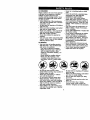
_Look
for this symbol to pointout
important safety precautions. It means
CAUTIONlll BECOMEALERTI!I YOUR
SAFETY IS INVOLVED.
_ CAU'rlON: In order to prevent
accidental starting when setting up,
transporting, adjusting or making repairs,
always disconnect spark plug wire and
place wire where it cannot contact spark
plug.
CAUTION: Do not coast down a hill
in neutral, you may lose control of the
tractor.
_, CAUTION: Tow only the attachments
that are recommended by and comply
with specificationsof the manufacturer of
your tractor. Use common sense when
towing. Operate only at the lowest
possible speed when on a slope. Too
heavy of a load, while on a slope, is
dangerous. Tires can lose traction with
the ground and cause you to lose control
of your tractor.
&(_WARNING: Engine exhaust, some of
its constituents, and certain vehicle
components contain or emit chemicals
known to the State of California to cause
cancer and birth defects or other reproductive harm.
_WARNING:
Battery posts, terminals
and related acoessodes contain lead and
lead compounds, chemicals known to the
State of California to cause cancer and
birth defects or other reproductive harm.
Wash hands after handling.
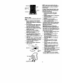
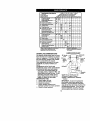
PRODUCT
SPECIFICATIONS
GASOLINE 1.25GALLONS
CAPACITY UNLEADED
ANDTYPE: REGULAR
OILTYPE
SAE30(ABOVE
32°F
API-SF.-SJ): SAE5W-30
(BELOW
32°F)
OILCAPACITY:
4.0PINTS
SPARK
PLUG: CHAMPION
RC12YC
GAP:
.040")
GROUND
SPEED
FORWARD:
(MPH):
1sT 1.2
2N°
1.5
3_
4TM
5TM
6TM
REVERSE:
2.4
3.5
4.8
5.3
1.5
16AMPS @ 3600 RPIV
BATTERY:
AMP/HR:
28
MIN. CCA: 230
CASE SIZE: U 1R
27-35 FT. LBS.
BLADE BOLT
TORQUE:
REPAIR AGREEMENT
A Repair Agreement is available on this
product. Contact your nearest Sears
store for details.
CUSTOMER
RESPONSIBILITIES
• Read and observe the safety rules.
• Follow a regular schedule in maintaining, caring for and using your tractor.
• Follow the instructionsunder =Maintenance" and "Storage" sections of this
owner's manual.
_WARNING:
This tractor is equipped
with an internal combustion engine and
should not be used on or near any
unimproved forest-covered, brushcovered or grass-covered land unless the
engine's exhaust system is equipped with
a spark an'ester meeting applicable local
or state laws (if any). If a spark an'esteris
used, it should be maintained in effective
working order by the operator.
In the state of Callfomia the above is
required by law (Section 4442 of the
Callfomia Public Resources Code).
Other states may have similar laws.
Federal laws apply on federal lands. A
spark arrester far the muffler is available
through your nearest Sears service
center (See REPAIR PARTS section of
this manual).
TIRE PRESSURE: FRONT: 14 PSI
REAR: 10 PSI
CHARGING
SYSTEM:
Please read and retain this manual. The
instructions will enable you to assemble
and maintain your tractor properly.
Always observe the "SAFETY RULES'.
CONGRATULATIONS on your purchase
of a new tractor. It has been designed,
engineered and manufactured to give you
the best possible dependability and
performance.
Should you experience any problem you
cannot easily remedy, please contact a
Sears or other qualified service center.
We have competent, well-trained technicians and the proper tools to service or
repair this tractor.
6
Steering Wheel
Steedng
Wheel Insert
(1) Large Flat Washer
(1) Hex Bolt 5/16-18 x 1-1/4
(1) Locknut 5/16-18_
/_
Steedng Wheel
Adapter
(1)Lock-washer
Steedng
3R
Shaft
Boot
(1) Washer
_
(1)
17/32
Knob
x 1-3/16 x 12 Gauge
For Future Use
€
Keys
Video
Slope Sheet
(2) Keys
Cassette
Your new tractor has been asseml_ed at the factory with exception of those parts left
unassembled for shipping purposes. To ensure safe and proper operation of your
tractor all parts and hardware you assemble must be tightened securely. Use the
correct tools as necessary to insure proper tightness. Review the video cassette before
you begin.
TOOLS REQUIRED FOR ASSEMBLY
A socket wrench set will make assembly
easier. Standard wrench sizes you need
are listed below.
(1) 9/16" wrench
(2) 1/2" wrench
(t) Utilityknife
(1) Pliers
(1) Tire pressure gauge
When dght or left hand is mentioned in
this manual, it means, from your point of
view, when you are in the operating
position (seated behind the steering
wheel).
TO REMOVETRACTOR
FROM
CARTON
UNPACK CARTON
1. Remove all accessible loose parts
and parts cartons from carton.
2. Cut, from top to bottom, along lines on
all four comers of carton, and lay
panels fiat.
3. Check for any additional loose parts
or cartons and remove.
BEFORE REMOVING TRACTOR
FROM SKID
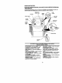
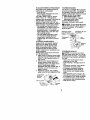
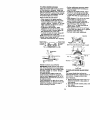
ATTACH STEERINGWHEEL
ASSEMBLE EXTENSION SHAFT AND
BOOT
1, Slide extension shaft onto lower
steedng shaft. Align mounting holes
in extension and lower shafts and
install 5/16 hex bolt and Iocknut.
Tighten securely.
2, Place tabs of steedng boot over tab
slots in dash and push down to
secure.
INSTALL STEERING WHEEL
3, Position front wheels of the tractor so
they are pointing straight forward.
4. Remove steering wheel adapter from
steedng wheel and slide adapter onto
steering shaft extension.
5. Position steering wheel so cross bars
are hodzontal (left to dght) and slide
inside boot and onto adapter.
6. Assemble large fiat washer, 3/8 lock
washer, 3/8 hex bolt and tighten
securely.
7. Snap steering wheel insert into center
of steering wheel.
8. Remove protective matedals from
tractor hood and grill.
IMPORTANT: Check for and remove any
staples in skid that may puncture tires
where tractoris to rolloff skid.
Insert
_//3/8
Hex Bolt
_./Lockwasher
_rag_F_at
Bteering_
Steenng
Wheel
_/Boot
:_
E_ta_nSi°n""_ _
Tabs
_A_
Adapter
5/16
5/16
Locknut _
_,_r./Hex
Lower
Steering_
-_ -"-L '_',
_" <':._-".
Shaft
_
.
, '
Bolt
Tab
HOWTO SET UPYOURTRACTOR
CHECK BATTERY
1. Lift seat pan to raised position and
open battery box door.
NOTE: If this battery is put into service
after month and year indicated on label
(label located between terminals) charge
battery for minimum of one hour at 6-10
amps. (See "BATTERY" in Maintenance
section of this manual for charging
instructions).
NOTE: You may now rollor drive your
tractor off the skid. Follow the appropriate
instructionbelow to remove the tractor
from the skid.
TO ROLLTRACTOR
OFF SKID (See
Operation section for location and
function of controls)
1. Press lift lever plunger and raise
attachment lift lever to its highest
position.
2. Release parking brake by depressing
clutch/brake pedal.
3. Place gearshift lever in neutral (N)
INSTALL
SEAT
Adjust
seatbefore
tightening
adjustment4. position.
Roll tractor forward off skid.
knob.
5. Remove banding holding deflector
1. Remove
adjustment
knobandfiat
shield up against tractor.
washer
secudng
seattocardboard
packing
andsetasideforassembly
of
seattotractor.
2. Pivotseat upward and remove from
3.
4.
5.
6.
7.
8.
9.
the cardboard packing. Remove the
cardboard packing and discard.
Place seat on seat pan so head of
shoulder bolt is positioned over large
slotted hole in pan.
Push down on seat to engage
shoulder bolt in slot and pull seat
towards rear of tractor.
Pivot seat and pan forward and
assemble adjustment knob and flat
washer loosely. Do not tighten.
Lower seat into operating position and
sit in seat.
Slide seat until a comfortable position
is reached which allows you to press
clutch/brake pedal all the way down.
Get off seat without moving its
adjusted position.
Raise seat and tighten adjustment
knob securely.
Seat
Bolt
Rat W her
TO DRIVETRACTOR
OFF SKID (See
Operation section for location and
function of controls)
_,WARNING: Before starting read
understand and follow a nstructons n
the Operation section of this manual. Be
sure tractor is in e well-ventilated area. Be
sure the area in front of tractor is clear of
other people and objects.
1. Be sure all the above assembly steps
have been completed.
2. Check engine oil level and fill fuel
tank with gasoline.
3. Sit on seat in operating position,
depress clutch/brake pedal and set
the parking brake.
4. Place gear shift lever in neutral (N)
position.
5. Press lift lever plunger and raise
attachment lift lever to its highest
position.
6. Start the engine. Afler engine has
started, move throttle control to idle
position.
7. Depress clutch/brake pedal into full
"BRAKE" position and hold. Move
gearshift laver to 1st gear.
8. Slowly release clutch/brake pedal and
slowly ddve tractor off skid.
9. Apply brake to stop tractor, set parking
brake and place gearshift lever in
neutral position.
10.Turn ignition key to "OFF" position.
Continue with the instructions that follow.
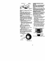
INSTALL
MULCHER
PLATE
(Ifpreviouslyremoved)
1. Raiseandholddeflector
shieldin
upright
position.
2. Place
front of mulcher plate over front
of mower deck opening and slide into
place, as shown.
3. Hook front latch into hole on front of
mower deck.
4, Hook roar latch into hole on back of
mower deck.
_I_CAUTION: Do not remove deflector
shield from mower. Raise and hold shield
when attaching mulcber plate and allow it
to rest on plate while in operation.
TO CONVERT TO BAGGING OR
DISCHARGING
Simply remove mulcher plate and store in
a safe place. Your mower is now ready for
discharging or installation of optional
grass catcher accessory.
NOTE: It is not necessary to change
blades. The mulcher blades are designed
for discharging and bagging also,
Deflector
Mulcher
CHECK TIRE PRESSURE
The tires on your tractor were overinflated
at the factory for shippingpurposes.
Correct tire pressure is important for best
cutting performance.
• Reduce tire pressure to PSI shown in
"PRODUCT SPECIFICATIONS" section
of this manual.
CHECK DECK LEVELNESS
For best cutting results, mower housing
should be propedy leveled, See "TO
LEVEL MOWER HOUSING" in the
Service and Adjustments section of this
manual.
CHECK FOR PROPER POSITION OF
ALL BELTS
See the figures that are shown for
replacing motion and mower blade ddve
belts in the Service and Adjustments
section of thismanual. Verifythat the pelts
are routed correctly.
CHECK BRAKE SYSTEM
After you learn how to operate your
tractor,check to see that the brake is
properly adjusted. See =TO ADJUST
BRAKE" in the Service and Adjustments
section of this manual.
Latch
Hooks
10
V'CHECKLIST
Before you operate and enjoy your new
tractor, we wish to assure that you receive
the best performance and satisfaction
from this quality product.
Please review the following checklist:
,/ All assembly instructions have been
completed.
/ No remaining loose parts in carton.
•/ Battery is propedy prepared and
charged.(Minimum 1 hour at 6 amps).
/ Seat is adjusted comfortably and
tightened securely.
•/ All tires are prepedy inflated. (For
shipping purposes, the tires were
ovednflated at the factory).
•/ Be sure mower deck is propedy leveled
side-to-sideifront-to-rearfor best cutting
results. (Tires must be propedy inflated
for leveling).
,/Check mower and ddve belts. Be sure
they are routed propedy around pulleys
and inside all belt keepers.
•/ Check wiring. See that all connections
are still secure and wires are properly
clamped,
While learning how to use your tractor,
pay extra attention to the following
important items:
,/Engine oil is at proper level.
,/" Fuel tank is filled with fresh, clean,
regular unleaded gasoline.
•/ Become familiar with all controls - their
location and function, Operate them
before you start the engine.
,/Be sure brake system is in safe operating condition.
11
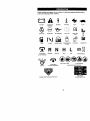
These symbols may appear on your tractor or in literature supplied with the product.
Learn and understand their meaning.
BATI'E RY
CAUTION
OR
REVERSE
FORWARD
FAST
SLOW
WARNING
ENG,NEOH
ENG,NEOFE
O,LPREESURE
L,G,TSON
O%_MP 1"
FUEL
CHOKE
MOWER
HEIGHT
r 'l R N
ATTACHMENT
CLUTCH ENGAGED
REVERSE
NEUTRAL
PARKING BRAKE
LOCKED
H
L
HIGH
LOW
KEEP AREA CLEAR
ATTACHMENT
CLUTCH DISENGAGED
IGNITION
(SEE SAFETY
UNLOCKED
MOWER
LIFT
PARKING BRAKE
ELOPE
RULES
HAZARDS
SECTION)
FREE WHEEL
DANGER,
KEEP
HANDS
AND FEET AWAY
(Automatic
12
Models only)
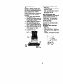
KNOWYOURTRACTOR
READTHIS
OWNER'S
MANUAL
ANDSAFETY
RULES
BEFORE
OPERATING
YOURTRACTOR
Compare
theillustrations
withyourtractor
tofami!iadze
yourself
withthe locationsof
vadouscontrolsand adjustments.
Save this manualfor futurereference.
Attachment
Clutch Lever
Ammeter
Light
IgniUon
Switch
Choke Con_o]
Lift
Lever
Thro_e
Attachment
Lift Lever
Control
Clutch/
_ Height
Adjustment
Indicator
Parking Brake
Gearshift
Lever
Our tractors conform to the safety standards of the Amedcan
National Standards Institute.
ATTACHMENT CLUTCH LEVER: Used
to engage the mower blades, or other
attachments mounted to your tractor.
LIGHT SWITCH: Turnsthe headlights on
and off.
THROTTLE CONTROL: Used for startiog
and controlling engine speed.
CHOKE CONTROL: Used when starting
a cold engine.
CLUTCH/BRAKE PEDAL: Used for
declutching and braking the tractor and
starting the engine.
PARKING BRAKE: Locks clutch/brake
pedal into the brake position.
GEARSHIFT LEVER: Selects the speed
and direction of tractor.
ATTACHMENT LIFT LEVER: Used to
raise, lower, and adjust the mower deck
or other attachments mounted to your
tractor.
LIFT LEVER PLUNGER: Used to release
attachment lift lever when changing its
position.
IGNITION SWITCH: Used for startingand
stopping the engine.
AMMETER: Indicates battery charging
(+) or discharging(-).
13
The operation of any tractor can result in foreign objects thrown into the |
eyes, which can result in severe eye damage. Always wear safety
glasses or eye shields while operating your tractor or performingany
adjustments or repairs. We recommend a wide vision safety mask over
spectacles, or standard safety glasses.
I
HOWTO USEYOURTRACTOR
TO SET PARKING BRAKE
Your tractor is equipped with an operator
presence sensing switch. When engine
is running, any attempt by the operator to
leave the seat without first setting the
parking brake will shut off the engine.
1. Depress clutch/brake pedal into full
"BRAKE" position and hold.
2. Place parking brake lever in =ENGAGED" position and release
pressure from clutch/brake pedal.
Pedal should remain in "BRAKE"
position. Make sure parking brake will
hold tractor secure.
Choke
Control
Attachment Clutch Lever
"Engaged" Position
Throttle
, Position
Parking Brake
Pedal '
"Disengaged"
posiSon
Position
"Brake"
Posi_on
Gearshift
Lever
STOPPING
MOWER BLADES • To stop mower blades,move attachment
clutch lever to "DISENGAGED" position.
GROUND DRIVE • To stop ground ddve, depress clutch/
brake pedal into full "BRAKE" position.
• Move gearshift lever to neutral (N)
position.
ENGINE• Move throttle control to slow position.
NOTE: Failure to move throttle control to
slow position and allowing engine to idle
before stopping may cause engine to
"backfire".
•Tum ignition key to =OFF" position and
remove key. Always remove key when
leaving tractor to prevent unauthorized
use,
• Never use choke to stop engine,
IMPORTANT: Leaving the ignition switch
in any position other than "OFF" will cause
the battery to be discharged, (dead).
NOTE: Under certain conditionswhen
tractor is standing idle with the engine
running, hot engine exhaust gases may
cause "browning"of grass. To eliminate
this possibility,always stop engine when
stopping tractor on grass areas.
_CAUTION:
Always stop tractor
completely, as described above, before
leaving the operator's position; to empty
grass catcher, etc.
TO USE THROTTLE CONTROL
Always operate engine at full throttle.
• Operating engine at less then full
throttle reduces the battery charging
rate.
• Full throttle offers the best bagging and
mower performance.
TO USE CHOKE CONTROL
Use choke control whenever you are
startinga cold engine. Do not use to start
a warm engine.
• To engage choke control, pull knob out.
Slowly push knob in to disengage.
TO MOVE FORWARD AND BACKWARD
The direction and speed of movement is
controlled by the gearshift lever.
1. Start tractor with clutch/brake pedal
depressed and gearshift lever in
neutral (N) position.
2. Move gearshift lever to desired
position.
3. Slowly release clutch/brake pedal to
start movement.
IMPORTANT: Bdng tractorto a complete
stop before shifting or changing gears.
Failure to do so will shorten the useful life
of your transaxle.
14
TO ADJUST MOWER CUTTING HEIGHT
TO OPERATE MOWER
The position of the attachment lift lever
Your tractor is equipped with an operator
determines the cutting height.
presence sensing switch. Any attempt by
• Grasp liftlever.
the operator to leave the seat with the
• Press plunger with thumb and move
engine running and the attachment clutch
lever to desired position,
engaged will shut off the engine.
The cuffing height range is approxi1. Select desired height of cut.
mately 1-1/2 to 4", The heights are
2. Start mower blades by engaging
attachment clutch control.
measured from the ground to the blade tip
with the engine not running. These
TO STOP MOWER BLADES heights are approximate and may vary
disengage attachment clutch control.
depending upon soil conditions, height of
_I, CAUTION: Do not operate the mower
gross and types of grass being mowed.
without either the entire grass catcher, on
• The average lawn should be cut to
mowers so equipped, or the deflector
approximately 2-1/2 inches dudng the
shield in place.
cool season and to over 3 inches
during hot months. For healthier and
Attachment Clutch
Attachment Lift Lever
better looking lawns, maw often and
Lever "Engaged"
High Position
after moderate growth.
Position
• For best cutting performance, grass
over 6 inches in height should be
mowed twice. Make the first cut
Low
Position
_ Position
relatively high; the second to desired
height.
TO ADJUST GAUGE WHEELS
Gauge wheels are properly adjusted
when they are slightly off the ground
Shield
when mower is at the desired cutting
height in operating position. Gauge
wheels then keep the deck in proper
position to help prevent scalping in most
terrain conditions.
TO OPERATE ON HILLS
NOTE: Adjust gauge wheels with tractor
_CAUTION: Do not drive up or down
on a flat level surface.
hills with slopes greater than 15° and do
1. Adjust mower to desired cutting height
not drive across any slope. A slope guide
(See "TO ADJUST MOWER CUTTING
at the back of your manual is provided for
HEIGHT" in the Operation section of
your use.
this manual).
• Choose the slowest speed before
2. With mower in desired height of cut
starting up or down hills.
position, gauge wheels should be
• Avoid stopping or changing speed on
assembled so they are slightly off the
hills.
ground. Install gauge wheel in
• If slowing is necessary, move throttle
appropdate hole with shoulder bolt, 3/
control lever to slower position.
8 washer, and 3/8-16 lecknut and
• if stopping is absolutely necessary,
tighten securely.
push clutch/broke pedal quickly to
3. Repeat for opposite side installing
brake position and engage parking
gauge wheel in same adjustment hole.
brake.
• Move gearshift lever to 1st gear. Be
Gauge Wheel
sure you have allowed room for tractor
to roll slightly as you restart movement.
Bracket
• To restart movement, slowly release
parking brake and clutch/broke pedal.
3/8-16 Locknut
• Make all turns slowly.
3/8 Washer
Gauge Wheel
houlder
_B_t
15
TO TRANSPORT
• Raise attachment lift to highest position
with attachment lift control.
• When pushing or towing your tractor,
be sure gearshift lever is in neutral (N)
position.
• Do not push or tow tractor at more than
five (5) MPH.
NOTE: To protect hood fi'om damage
when transporting your tractor on a truck
or a trailer, be sure hood is closed and
secured to tractor. Use an appropriate
means of tying hood to tractor (rope, cord,
etc.).
TOWING CARTS AND OTHER ATTACHMENT8
Tow only the attachments that are
recommended by and comply with
specificationsof the manufacturer of your
tractor. Use common sense when towing.
Too heavy of a load, while on a slope, is
dangerous. Tires can lose traction with
the ground and cause you to lose control
of your tractor.
BEFORE STARTING THE ENGINE
CHECK ENGINE OIL LEVEL
The engine in your tractor has been
shipped, from the factory, already filled
with summer weight oil.
1. Check engine oil with tractor on level
ground.
2. Remove oil fill cap/dipstick and wipe
clean, reinsert the dipstick and screw
cap tight, wait for a few seconds,
remove and read oil level. If necessary, add oil until "FULL" mark on
dipstickis reached. Do not overfll.
• For cold weather operation you should
change oilfor easier staring (Sea "OIL
VISCOSITY CHART" in the Maintenance section of this manual).
• To change engine oil, see the Maintenance section in this manual.
ADD GASOLINE
• Fill fuel tank. Use fresh, clean, regular
unleaded gasoline with a minimum of
87 octane. (Use of leaded gasoline will
increase carbon and lead oxide
deposits and reduce valve life). Do not
mix oil with gasoline. Purchase fuel in
quantities that can be used within 30
days to assure fuel freshness.
IMPORTANT: When operelJngin temperatures below 32°F(0°C), use fresh,
clean winter grade gasoline to help
insure good cold weather starting.
_,WARNING: Experience indicates that
alcohol blended fuels (called gasehol or
using ethanol or methanol) can attract
moisture which leads to separation and
formation of acids dudng storage. Acidic
gas can damage the fuel system of an
engine while in storage. To avoid engine
problems, the fuel system should be
emptied before storage of 30 days or
longer. Drain the gas tank, start the
engine and let it run until the fuel lines
and carburetor are empty. Use fresh fuel
next season. See Storage Instructionsfor
additional information. Never use engine
or carburetor cleaner productsin the fuel
tank or permanent damage may occur.
_LCAUTION: Fill to bottom of gas tank
filler neck. Do not overfill.Wipe off any
spilled oil or fuel. Do not store, spill or use
gasoline near an open flame.
16
TO START ENGINE
When star6ngtbe en_ee for6_efirst_z_eor if
the en_ne has mn out offnel,it wil tak_ extra
cranking6me to move fuethorn the tankto the
engine.
1. Sit on seat in operating position,
depress clutch/brake pedal and set
parking brake.
2. Place gear shift lever in neutral (N)
position.
3. Move attachment clutch to _DISENGAGED" position.
4. Move throttle control to fast position
5. Pull choke control out for a cold
engine start attempt. For a warm
engine start attempt the choke control
may not be needed.
NOTE: Beforestarting,read the warm and
cd,d star'dngproceduresbelow.
6. Insert key into ignition and turn key
clockwise to "START" position and
release key as soon as engine starts.
Do not run starter continuouslyfor
more than fifteen seconds per minute.
If the engine does not start after
several attempts, push choke control
in, wait a few minutes and try again. If
engine still does not start, pull the
choke control out and retry.
WARM WEATHER STARTING (50° F and
above)
7. When engine starts, slowly push
choke control in until the engine
begins to run smoothly. If the engine
starts to run roughly, pull the choke
control out slightly for a few seconds
and then continue to push the control
in slowly.
• The attachments and ground drive can
now be used. If the engine does not
accept the load, restart the engine and
allow it to warm up for one minute using
the choke as descdbed above.
COLD WEATI-IERSTARTING (50° F and
below)
7. When engine starts, slowly push
choke control in until the engine
begins to run smoothly. Continue to
push the choke control in small steps
allowing the engine to accept small
changes in speed and load, until the
choke control is fully in. If the engine
starts to run roughly, pull the choke
control out slightlyfor a few seconds
and then continue to push the control
in slowly. This may require an engine
warm-up period from several seconds
to several minutes, depending on the
temperature.
• The attachments can be used during
the engine warm-up pedod and may
require the choke control be pulled out
slightly.
NOTE: If at a high altitude (above 3000
feet) or in cold temperatures (below 32 F)
the carburetor fuel mixture may need to
be adjusted for best engine performance.
See =TO ADJUST CARBURETOR" in the
Service and Adjustments section of this
manual.
17
MOWlNGTIPS
• Mower should be propedy leveled for
best mowing performance. See °TO
LEVEL MOWER HOUSING" in the
Service and Adjustments section of this
manual.
• The left hand side of mower should be
used for trimming.
• Drive so that clippi_Js are discharged
onto the area that has been cut. Have
the cut area to the right of the machine.
This will result in a more even distdbution of clippings and more uniform
cutting.
• When mowing large areas, start by
turning to the dght so that clippings will
discharge away from shrubs, fences,
driveways, etc. After one or two
rounds,
mow in the opposite direction making
left hand turns until finished
• If grass is extremely tall, it should be
mowed twice to reduce load and
possible fire hazard from dried clippings. Make first cut relatively high; the
second to the desired height.
• Do not mow grass when it is wet. Wet
grass will plug mower and leave
undesirable clumps. Allow grass to dry
before mowing.
• Always operate engine at full throttle
when mowing to assure better mowing
performance and proper discharge of
material. Regulate ground speed by
selecting a low enough gear to give the
mower the best cutting performance as
well as the quality of cut desired.
• When operating attachments, select a
ground speed that will suit the terrain
and give best performance of the
attachment being used,
MULCHING MOWlNGTIPS
IMPORTANT: For best performance,
keep mower housing free of built-upgrass
and trash. Clean after each use.
• The special mulching blade will recur
the grass clippings many times and
reduce them in size so that as they fall
onto the lawn they will disperse into the
grass and not be noticed. Also, the
mulched grass will biodegrade quickly
to provide nutrientsfor the lawn.
Always mulch with your highest engine
(blade) speed as this will provide the
best recurring action of the blades.
• Avoid cuffing your lawn when it is wet.
Wet grass tends to form clumps and
interferes with the mulching action. The
best time to mow your lawn is the early
afternoon. At this time the grass has
dried and the newly cut area will not be
exposed to the direct sun.
• For best results, adjust the mower
cutting height so that the mower cuts off
only the top one-third of the grass
blades. For extremely heavy mulching,
reduce your width of cut on each pass
and mow slowly.
• Certain types of grass and grass
conditions may require that an area be
mulched a second time to completely
hide the clippings. When doing a
second cut, mow across or perpendicular to the first cut path.
• Change your cutting pattern from week
to week. Mow north to south one week
then change to east to west the next
week. This will belp prevent matting
and graining of the lawn.
Max 1/3
18
__
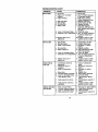
MAINTENANCESCHEDULE
_
e _
_
AS yOU _PLE_E
REGULAR SERVICE
c_._T.._m,.
Ch_
v' !t/
Opemto{ Pr_eno_ and
v'
R
iv" I
sham_Repta_
Mo*=Blade.
u_o.c.=,
1/4
vt
V'
c_.
V*
I/
ea_,y a_ T_iral8
Check Tra_axke C_Ex_@
M just Blade Belt(s) Tension
AdjustMOtion C(ive Belt(s) T_
c_
G
Engir_
C__el
_
if'
t/
Inspect MufflerlSpark A_'ester
Re place Air Filter PaPer Ca_id ge
(t/=
Red,ace Fuel Fi_r
GENERAL RECOMMENDATIONS
The warranty on this tractordoes not cover
items that have been subjectedto operator
abuse or negligence. To receive full value
from the warranty,operator must maintain
tractoras instructedin this manual.
Some adjustments will need to be made
periodicallyto properly maintain your
tractor.
All adjustments in the Sorv_ceand
Adjustmentssection of this manual should
be checked at least once each season.
• Once a year you shouldreplace the
spark plug, clean or replace air filter, and
check blades and belts for wear. A new
spark plug and clean air filter assure
proper air-fuel mixture and help your
engine run better and last longer.
BEFORE EACH USE
1. Check engine oil level.
2. Check brake operation.
3. Check tire pressure.
4. Check operator presence and
intedock systems for proper operation.
5. Check for loose fasteners.
I_
LUBRICATION CHART
Zerk
- Spindle
Zerk
(_ Front
_)
Wheel
Bearing
Zerk
Bearing
Zerk
@
I
Gearshift
"--J
'-~-"
Pivots
0)SAE 30 or 10w30 motor oil
(_General Purpose Grease
Refer to Maintenance "ENGINE"
Section
IMPORTANT: Do not oil or grease the
pivot points which have special nylon
bearings. Viscous lubricantswill attract
dust and dirt that will shorten the life of the
self-lubricatieg bearings. If you feel they
must be lubricated, use only a dry, powdered graphite type lubricant sparingly.
19
TRACTOR
Always observe safety roles when
performing any maintenarme.
BRAKE OPERATION
If tractor requires more than six (6) feet
stopping distance at high speed in
highest gear, then brake must be adjusted. (See "TO ADJUST BRAKE" in the
Service and Adjustments section of this
manual).
TIRES
• Maintain proper air pressure in all tires
(See "PRODUCT SPECIFICATIONS"
section of this manual).
• Keep tires free of gasoline, oil, or insect
control chemicals which can harm
rubber.
• Avoid stumps, stones, deep rots, sharp
objects and other hazards that may
cause tire damage.
NOTE: To seal tire punctures and prevent
flat tires due to slow leaks, tire sealant
may be purchased from your local parts
dealer. Tire sealant also prevents tire dry
rot and corrosion.
OPERATOR PRESENCE SYSTEM
Be sure that operator presence and
intedock systems are working properly. If
your tractor does not function as described below, repair the problem
immediately.
• The engine should not start unless the
clutch/brake pedal is fully depressed
and attachment clutch control is in the
disengaged position.
• When the engine is running, any
attempt by the operator to leave the
seat without first setting the parking
brake should shut off the engine.
• When the engine is running and the
attachment dutch is engaged, any
attempt by the operator to leave the
seat should shut offthe engine.
• The attachment clutch should never
operate unless the operator is in the
seat.
BLADE CARE
For best results mower blades must be
kept sharp. Replace bent or damaged
blades.
BLADE REMOVAL
1. Raise mower to highest position to
allow access to blades.
2. Remove hex bolt, lock washer and fiat
washer secudng blade.
3. Install new or resharpened blade with
trailing edge up towards deck as
shown.
IMPORTANT: To ensure proper ase_
center hole in blade must align with
on mandrel assembly.
4. Reassemble hex belt, lock wash,
fiat washer in exact order as sho
5. Tighten holt securely (27-35 Ft. L
torque).
IMPORTANT: Blade bolt is grade 8
treated.
TrailingEdgeUp
Mandrel,As
"BladeCenter _'_
FlatWasher_:_-_l"i
'e
Lock _,_"__.
_--Hex Bolt (Grade_8_)
*
•A Grade8 heattreatedboltcanbe ida
by six lines on thebolt head.
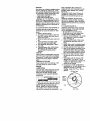
TO SHARPEN BLADE
NOTE: We do not recommend shaq
ing blade - but if you do, be sure the
is balanced.
Care should be taken to keep the bl;
balanced. An unbalanced blade wil
cause excessive vibration and even
damage to mower and engine.
• The blade can be sharpened with
or on a grinding wheel. Do not atl
to sharpen while on the mower.
• To check blade balance, you will
a 5/8" diameter steel bolt, pin, or
balancer. (When using a cone ba
ancer, follow the instructions supl
with balancer.)
NOTE: Do not use a nail for balanc
Idade. The lobes of the center hole
appear to be centered, but are not.
• Slide blade on to an unthreaded I
of the steel bolt or pin and hold th
or pin parallel with the ground. If
is balanced, it should remain in a
horizontal position. If either end c
blade moves downward, sharpen
heavy end until the blade is bolal
5/8"
or Pin-_e
20
lade
ntJHol_
BATTERY
Your tractorhas a battery charging system
which is sufficientfor normal use. However, periodic charging of the battery with
an automotive charger will extend its life.
• Keep battery and terminals clean.
• Keep battery bolts tight.
• Keep small vent holes open.
• Recharge at 6-10 amperes for 1 hour.
NOTE: The original equipment battery on
your tractor is maintenance free. Do not
attempt to open or remove caps or covers.
Adding or checking level of electrolyte is
not necessary.
TO CLEAN BATTERY AND TERMINALS
Corrosion and dirt on the battery and
terminals can cause the battery to "leak"
power.
1. Remove terminal guard.
2. Disconnect BLACK battery cable first
then RED battery cable and remove
battery from tractor.
3. Rinse the battery with plain water and
dry.
4. Clean terminals and battery cable
ends with wire brush until bright.
5. Coat terminals with grease or petroleum jelly.
6. Reinstall battery (See "REPLACING
BATTERY" in the SERVICE AND
ADJUSTMENTS section of this
manual).
V-BELTS
Check V-belts for deterioration and wear
after 100 hours of operation and replace
if necessary. The belts are not adjustable.
Replace belts if they begin to slip from
wear.
TRANSAXLE COOLING
Keep transaxle free from build-up of dirt
and chaff which can restdct cooling.
ENGINE
LUBRICATION
Only use high quality detergent oil rated
with API service classification SF-SJ.
Select the oil's SAE viscositygrade
according to your expected operating
temperature.
SAE VISCO_y
when used above 32°F. Check your
engine oil level more frequently to avoid
possible engine damage from running
low on oil.
Change the oil after every 50 hours of
operation or at least once a year if the
tractor is not used for 50 hours in one
year.
Check the crankcase oil level before
starting the engine and after each eight
(8) hours of operation, Tighten oil fill cap/
dipstick securely each time you check the
oil level.
TO CHANGE ENGINE OIL
Determine temperature range expected
before oil change. All oil must meet API
service classification SF-SJ.
• Be sure tractor is on level surface.
• Oil will drain more freely when warm.
• Catch oil in a suitable container.
1. Remove oil fill cap/dipstick. Be careful
not to allow dirt to enter the engine
when changing oil.
2. Remove cap from end of drain valve
and install the drain tube onto the
fitting.
3. Unlock drain valve by pushing inward
slightly and turning counterclockwise.
4. To open, pull out on the drain valve.
5. After oil has drained completely, close
and lock the drain valve by pushing
inward and tuming clockwise until the
pin is in the locked position as shown.
6. Remove the drain tube and replace
the cap onto to the end of the drain
valve.
7. Refill engine with oil through oil fill
dipsticktube. Pour slowly. Do not
overfill. For approximate capadty see
=PRODUCT SPECIFICATIONS"
section of this manual.
8. Use gauge on oil fill cap/dipstickfor
checking level. Be sure dipstick cap is
tightened securely for accurate
reading. Keep oil at "FULL" line on
dipstick.
Oil DrainValve
GRAOLS
Locked I
1
_
so-
position _
NOTE: Although multi-viscosity oils
(5W30. 10W30 etc.) improve starting in
cold weather, these mutii-viscesity oils
will result in increased oil consumption
Cap _
21
__
brain Tube
CLEAN AIR SCREEN
Air screen must be kept free of dirt and
chaff to prevent engine damage from
overheating. Clean with a wire brush or
compressed air to remove dirt and
stubborn dded gum fibers.
CLEAN AIR INTAKE/COOLING AREAS
To insure proper cooling, make sure the
grass screen, cooling fins, and other
extemal surfaces of the engine are kept
clean at all times.
Every 100 hours of operation (more often
under extremely dusty, dirty conditions),
remove the blower housing and other
cooling shrouds. Clean the cooling fins
and external surfaces as necessary. Make
sure the cooling shrouds are reinstalled.
NOTE: Operating the engine with a
blocked grass screen, dirty or plugged
cooling fins, and/or cooling shrouds
removed will cause engine damage due
to overheating.
AIR FILTER
Your engine will not run properly using a
dirty air filter. Clean the foam pre-cleaner
after every 25 hours of operation or every
season. Service paper cartridge every
100 hours of operation or every season,
whichever occurs first.
Service air cleaner more often under
dusty conditions.
1. Remove knobs and cover.
TO SERVICE PRE-CLEANER
2. Wash it in liquid detergent and water.
3. Squeeze it dry in a clean cloth.
4. Saturate it in engine oil. Wrap it in
clean, absorbent cloth and squeeze to
remove excess oil.
NOTE: If very dirty or damaged, replace
pre-cleaner.
TO SERVICE CARTRIDGE
5. Clean cartridge by tapping gently on
fiat surface. If very dirty or damaged,
replace cartridge.
6. Reinstall precleaner cartridge, cover
and secure with knobs.
IMPORTANT: Petroleum solvents, such
as kerosene, are not to be used to clean
the cartridge. They may cause deterioration of the cartridge. Do not oil cartridge.
Do not use pressurized air to clean or dry
cartridge.
Foam
Pre-Clean'_er_
ENGINE OIL FILTER
Replace the engine oil filter every season
or every other oil change if the tractor is
used more than 100 hours in one year.
MUFFLER
Inspect and replace corroded muffler and
spark arrester (if equipped) as it could
create a fire hazard and/or damage.
SPARK PLUGS
Replace spark plugs at the beginning of
each mowing season or after every 100
hours of operation, whichever occurs first.
Spark plug type and gap setting are
shown in =PRODUCT SPECIFICATIONS"
section of this manual.
IN-LINE FUEL FILTER
The fuel filter should be replaced once
each season. If fuel filter becomes
clogged, obstructing fuel flow to carburetor, replacement is required.
1. With engine cool, remove filter and
plug fuel line sections.
2. Place new fuel filter in position in fuel
line with arrow pointing towards
carburetor.
3. Be sure there are no fuel line leaks
and clamps are propedy positioned.
4. Immediately wipe up any spilled
gasoline.
Clamp
__
22
Clamp
Filter
CLEANING
• Clean engine, battery, seat, finish, etc.
of all foreign matter.
• Keep finished surfaces and wheels free
of all gasoline, oil, etc.
• Protect painted surfaces with automotive type wax.
We do not recommend using a garden
hose to clean your tractor unless the
electrical system, muffler, air filter and
carburetor are covered to keep water out.
Water in engine can result in a shodened
engine life.
,_CAUTION:
BEFORE PERFORMING ANY SERVICE OR ADJUSTMENTS:
1. Depress clutch/brake pedal fully and set parking brake.
2. Place gearshift lever in neutral (N) position.
3. Place attachment dutch in =DISENGAGED" position.
4, Tum ignition key =OFF" and remove key.
5. Make sure the blades and all moving parts have completely stopped.
6. Disconnect spark plug wire from spark plug and place wire where it cannot
come in contact wRh plug.
TRACTOR
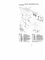
TO REMOVE MOWER
Mower will be easier to remove from the
dght side of tractor.
1. Place attachment dutch in "DISENGAGED" position.
2, Move attachment liRlever forward to
lower mower to its lowest position.
3. Roll belt off engine pulley.
4. Remove small retainer spdng, and lift
clutch spdng off pulley bolt.
5. Remove large retainer spdng, slide
collar off and push housing guide out
of bracket.
6. Disconnect anti-swaybar from chassis
bracket by removing retainer spring.
7. Disconnect suspension arms from
rear deck brackets by removing
retainer spdngs.
8. Disconnect front links from deck by
removing retainer spdngs.
9. Raise lift lever to raise suspension
arms. Slide mower out from under
tractor.
IMPORTANT: If an attachment other than
the mower deck is to be mounted on the
tractor, remove the front links and hook
the clutch spdng Into square hole in
frame.
TO INSTALL MOWER
1. Raise attachment lift lever to Rs
highest position.
2. Slide mower under tractor with
discharge guard to dght side of tractor.
3. Lower lift lever to its lowest position.
4. Install mower in reverse order of
removal instructions.
Small Retainer Spdng
SuspensionArms
-""*:";"°'_-_"
Square Hole
Clutch
Retainer Spdng
Anti-Swa
Front Link
Collar
Housing
(Both Sides)
Large
Spring
Bracket
23
TO LEVEL MOWER HOUSING
Adjust the mower while tractor is parked
on level ground or driveway. Make sure
tires are propedy inflated (See =PRODUCT
SPECIFICATIONS" section of this manual).
if tires are over or undednflated, you will
not properly adjust your mower.
SIDE-TO-SIDE ADJUSTMENT
• Raise mower to its highest position.
• At the midpoint of both sides of mower,
measure height from bottom edge of
mower to ground. Distance "A" on both
sides of mower should be the same or
within 1/4" of each other.
• If adjustment is necessary, make
adjustment on one side of mower only.
• To raise one side of mower, tighten lift
link adjustment nut on that side.
• To lower one side of mower, loosen lift
link adjustment nut on that side.
NOTE: Each full turn of adjustment nut will
change mower height about 1/8".
• Recheck measurements after adjusting.
BottomEd-_
of Mowerto_"_F'_
_/_--_of
Before making any necessary adj_
ments, check that both front links a
equal in length.
" If links are not equal in length, adjt
one link to same length as other lit
" To lower front of mower loosen nul
on both front links an equal numbc
turns.
When distance "D° is liB" to 112"k
at front than rear, tighten nuts "F"
against trunnion on both front link.,
To raise front of mower, loosen nu
from trunnion on both front links.
Tighten nut "E" on both front links
equal number of turns.
When distance "D" is 1/8" to 112" k
at front than rear, tighten nut _F" ag
trunnion on both front links.
Recheck side-to-side adjustment,
Mandrel
o
•
o
BottomEdge
Mowerto
BothFrontUnks Shouldbe Equalin Le
AI
_, VGmundLine V J LA
Suspension
Arm
Nut "F"_
Nut '
Lift Unk Adjustment
Nut
FRONT-TO-BACK ADJUSTMENT
IMPORTANT: Deal(.must be level side-toside. If the following front-to-back adjustment is necessary, be sure to adjust both
front links equally so mower will stay
level side-to-side.
To obtain the best cutting results, the
mower housing should be adjusted so
that the front is approximately 118"to 1/2"
lower than the rear when the mower is in
its highest position.
Check adjustment on right side of tractor.
Measure distance "D" directly in front and
behind the mandrel at bottom edge of
mower housing as shown.
Trunnion
_
_
Front Links
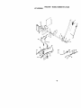
TO REPLACE MOWER BLADE DRr
BELT
The mower blade drive belt may be
replaced without tools. Park the tracl
level surface. Engage parking brake
BELT REMOVAL 1. Remove mower from tractor (See
REMOVE MOWER" in this sectiol
this manual).
2, Work belt off both mandrel pulley
idler pulleys.
3. Pull belt away from mower.
24
BELT INSTALLATION 4. Install new belt in reverse order of
removal.
5. Make sure belt is in all pulley grooves
and inside all belt guides.
6. Install mower in reverse order of
removal instructions.
Mandrel
Idler Pulleys
TO ADJUST BRAKE
Your tractor is equipped with an adjustable brake system which is mounted on
the dght side of the transaxle.
If tractorrequires more than six (6) foot
stoppingdistance at high speed in highest
gear on a level dry concrete or paved
surface, then brake must be adjusted.
1. Depress clutch/brake pedal and
engage parking brake.
2. Measure distance between brake
operating arm and nut "A" on brake
rod.
3. If distance is other than 1-1/2", loosen
jam nut and turn nut "A"until distance
becomes 1-1/2". Retighten jam nut
against nut "A'.
4. Road test tractor for proper stopping
distance as stated above. Readjust if
necessary. If stopping distance is still
greater than six (6) feet in highest
gear, further maintenance is necessary, Contact a Sears or other
qualified service center.
With parking Brake
"Engaged"
Nut "A"
Jam Nut
TO REPLACE MOTION DRIVE BELT
Park the tractor on level surface. Engage
parking brake. For assistance, there is a
belt installation guide decal on bottom
side of left footrest.
1. Remove mower (See "TO REMOVE
MOWER" in this section of this
manual.)
2. Remove belt from stationary idler and
clutching idler.
3. Pull belt slack toward rear of tractor.
Remove belt upwards from transaxle
pulley by deflecting belt keepers.
4. Pull belt toward front of tractorand
remove downwards from around
engine pulley.
5. Install new belt by reversing above
procedure,
Engine
Pulley
C_utching
Idler
Stationar
Idler
Transaxle
Pulley
TRANSAXLE GEAR SHIFT LEVER
NEUTRAL ADJUSTMENT
The tmnsaxle should be in neutral when
the gear shill lever is in neutral (N) (lock
gate) position.The adjustment is preset at
the factory; however, if adjustment is
needed, proceed as follows:
1. Make sure transaxle is in neutral (N).
NOTE: When the tractor rear wheels move
freely, the transaxle is in neutral.
2. Loosen adjustment bolt in front of the
dght rear wheel.
3. Position the gear shift lever in the
neutral (N) position.
4. Tighten ad)ustment bolt securely.
NOTE: If additional clearance is needed
to get to adjustment bolt, move mower
deck height to the lowest position.
Operating Arm
25
Gearshift Lever
TO START ENGINEWlTH AWEAK
BA'n'ERY
Neutral
Lock Gate
Adjustment
Bolt
..,
TO ADJUST STEERING WHEEL ALIGNMENT
If steering wheel crossbars are not
hodzontal (left to right) when wheels are
positioned straight foi_vard, remove
steedng wheel and reassemble per
instructionsin the Assembly section of this
manual.
FRONT WHEEL TOE-INICAMBER
The front wheel tee-in and camber are not
adjustable on your tractor. If damage has
occurred to affect the front wheel toe-in or
camber, contact a Sears or other qualified
service center.
TO REMOVE WHEEL FOR REPAIRS
1. Block up axle securely.
2. Remove axle cover, retaining ring and
washers to allow wheel removal (rear
wheel contains a square key - Do not
lose).
3. Repair tire and reassemble.
NOTE: On rear wheels only: align
grooves in rear wheel hub and axle.
Insert square key.
4. Replace washers and snap retaining
dng securely in axle groove.
5. Replace axle cover.
NOTE: To seal tire punctures and prevent
fiat tires due to slow leaks, tire sealant
may be purchased from your local parts
dealer. Tire sealant also prevents tire dry
rot and corrosion.
TO ADJUST CHOKE CONTROL
A_P-_TION: Lead-aoldbatteriesgenerate
explosiveg_.
Keep sparks,flame and
smokingmaterialsaway from batteries.
Always wear eye protectionwhen around
batteries.
If yourbatteryistooweak tostartthe engine, it
shouldbe recharged. (See "BATTERY"in the
MAINTENANCE _
of thismanual).
if"jumper cables" are used for emergency
starting,folow this procedure:
IMPORTANT: Your tractor is equipped with a
12 volt eagati_ groundedsystem.The other
vehicalmust also be a 12 voltnegative
groundedsystem. Do not use yourtractor
battery to startothervehicles.
TO ATTACHJUMPER CABLES 1. Connect each end of the RED cable to
the POSITIVE (+) terminal of each
battery, taking care not to short
against chassis.
2. Connect one end of the BLACK cable
to the NEGATIVE (-) terminal of fully
charged battery.
3. Connect the other end of the BLACK
cable to good CHASSIS GROUND,
away from fuel tank and battery.
TO REMOVE CABLES, REVERSE ORDER 1. BLACK cable first from chassis and
then from the fully charged battery.
2. RED cable last from both batteries.
Positive Terminal
_._
Axle Cover
' Cables
_.Charged
Battery
Washers
Retaining
Ring
=Terminal
_._
_,_
Square Key
(Rear Wheel Only)
26
REPLACING BATTERY
4_CAUT!ON: Do not short battery
terminals oy allowing a wrench or any
other object to contact beth terminals at
the same time. Before connecting battery,
remove metal bracelets, wristwatch
bands, rings, etc.
Positive terminal must be connected first
to prevent sparking from accidental
grounding.
1. Lift seat pan to raised position and
open battery box door.
2. Disconnect BLACK battery cable first
then RED battery cable and carefully
remove battery from tractor.
3. Install new battery with terminals in
same position as old battery.
4. First connect RED battery cable to
positive (+) terminal with hex bolt and
keps nut as shown. Tighten securely.
5. Connect BLACK grounding cable to
negative (-) terminal with remaining
hex belt and keps nut. Tighten
securely.
6. Close battery box door.
TO REPLACE HEADLIGHT BULB
1. Raise hood.
2. Pull bulb holder out of the hole in the
backside of the grill.
3. Replace bulb in holder and push bulb
holder securely back into the hole in
the backside of the grill.
4. Close hoed.
INTERLOCKS
AND RELAYS
Loose or damaged wiring may cause your
tractorto run pondy,stop running, or
prevent it from star6ng.
• Check widng. See electrical wiring
diagram in the Repair Parts section.
TO REPLACE FUSE
Replace with 20 amp automotive-type
plug-in fuse. The fuse holder is located
behind the dash.
TO REMOVE HOOD AND GRILL
ASSEMBLY
1. Raise hoed.
2. Unsnap headlight wire connector.
3. Stand in front of tractor. Grasp hoed at
sides, tilt toward engine and lift off of
tractor.
4. To replace, reverse above procedure.
Batter
Box Door
Keps
Hex
Connector
Positive
_Red)
uable
t
NegaUve
(Black) Cable
27
ENGINE
TO ADJUST CARBURETOR
Maintenance,repair,or replacementof
entssion controldevicesand systems,which
am beingdene at the customersexpense,
may be performed by any non-roadengine
repairestablishmentor individual. Warranty
repa_ must be performedby an autbedznd
engine manufacturer'sservice outfaL
TO ADJUST THROTTLE CONTROL
CABLE
The throttle control has been preset at the
factory and adjustment should not be
necessary. Check adjustment as described below before loosening cable. If
adjustment is necessary, proceed as
follows:
1. With engine not running, move throttle
control lever to fast position.
2. Check that swivel is against stop. If it is
not, loosen cable clamp screw and
pull cable back until swivel is against
stop. Tighten cable clamp screw
securely.
TO ADJUST CHOKE CONTROL
The choke control has been preset at the
factory and adjustment should not be
necessary. Check adjustment as described below before loosening cable. If
adjustment is necessary, proceed as
follows:
1. With engine not running, move choke
control (located on dash panel) to full
choke position.
2. Loosen knob and remove cover
assembly from air cleaner.
3. Choke should be closed. If it is not,
loosen casing clamp screw and move
choke cable until choke is completely
closed. Tighten casing clamp screw
securely.
4. Replace air cleaner cover assembly
and tighten knob.
Your carburetor is not adjustable, If your
engine does not operate propedy due to
suspected carburetor problems, take your
tractor to an authorized service center for
repair and/or adjustment,
High speed stop is factory adjusted. Do
not adjust - damage may result.
IMPORTANT: Never tamper with the
engine governor, which is factory set for
proper engine speed. Overspeeding the
engine above the factory high speed
setting can be dangerous. If you think the
engine-governed high speed needs
adjusting, contacta Sears or other qualified
set,ca center,,which has propor equip*
ment and expedence to make any
necessary adjustments.
Sto
Swivel
Claml:
28
Clamp
Screw
n_,
Also, experiance indicates that alcohol
Immediately prepare your tractor for
blended fuels (called gasohol or using
storage at the end of the season or if the
ethanol or methanol) can attract moisture
tractor will not be used for 30 days or
which leads to separation and formation
more.
of acids dudng storage. Acidic gas can
_kCAUTION
Never store the tractor with
damage the fuel system of and engine
gasoline in the tank inside a bu ding
while in storage.
where fumes may reach an open flame or
1. Drain the fuel tank.
spark. Allow the engine to cool before
2. Start the engine and let it run until the
storing in any enclosure.
fuel lines and carburetor are empty.
TRACTOR
• Never use engine or carburetor cleaner
Remove mower from tractor for winter
productsin the fuel tank or permanent
damage may occur.
storage. When mower is to be stored for
• Use fresh fuel next season.
a period of time, clean it thoroughly,
NOTE: Fuel stabilizer is an acceptable
remove all dirt, grease, leaves, etc. Store
altemative in minimizing the formation of
in a clean, dry area.
fuel gum deposits dudng storage. Add
1. Clean entire tractor (See "CLEANING"
in the Maintenance section of this
stabilizer to gasoline in fuel tank or
storage container. Always follow the mix
manual),
ratio found on stabilizer container. Run
2. Inspect and replace belts, if necessary
engine at least 10 minutes after adding
(See belt replacement instructions in
stabilizer to allow the stabilizer to reach
the Service and Adjustments section
the carburetor. Do not drain the gas tank
of this manual).
3. Lubdcate as shown in the Mainteand carburetor if using fuel stabilizer.
ENGINEOIL
nance section of this manual.
4. Be sure that all nuts, bolts and screws
Drain oil (with engine warm) and replace
are securely fastened. Inspect moving with clean engine oil. (See "ENGINE" in
parts for damage, breakage and wear.
the Maintenance section of this manual).
Replace if necessary.
CYLINDER(S)
5. Touch up all rusted or chipped paint
1. Remove spark plug(s).
surfaces; sand lightly before painting.
2. Pour one ounce of oil through spark
BATTERY
plug hole(s) into cylinder(s).
3. Turn ignition key to "START" position
• Fully charge the battery for storage.
for a few seconds to distributeoil.
• After a pehed of time in storage, battery
4.
Replace with new spark plug(s).
may require recharging.
• To help prevent corrosion and power
OTHER
leakage dudng long periods of storage,
• Do not store gasoline from one season
battery cables should be disconnected
to another.
and battery cleaned thoroughly (see
• Replace your gasoline can if your can
"TO CLEAN BATrERY AND TERMIstarts to rust. Rust and/or dirt in your
NALS" in the Maintenance section of
gasoline will cause problems.
this manual).
• If possible, store your tractor indoors
• After cleaning, leave cables disconand cover it to give protection from dust
nected and place cables where they
and dirt.
cannot come in contact with battery
• Cover your tractor with a suitable
terminals.
protective cover that does not retain
• If battery is removed from tractorfor
moisture. Do not use plastic. Plastic
storage, do not store battery directly on
cannot breathe which allows condenconcrete or damp surfaces.
sation to form and will cause your
tractorto rust.
ENGINE
IMPORTANT: Never cover tractor while
FUEL SYSTEM
engine and exhaust areas are still warm.
IMPORTANT: It is important to prevent
gum depesites from forming in essential
fuel system parts such as carburetor, fuel
hose, or tank dudng storage.
29
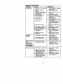
TROUBLESHOOTING
CHART
PROBLEM
Willnotstart
CAUSE
1. Out offuel.
2. Engine not "CHOKED"
properl_
3, Engine flooded.
Hard to start
1. Dirty air filter.
2. Bed spark plug.
3. Weak or dead battery.
4.
5.
6.
7.
8.
Englnewlll not
tum over
1. Clean/replace air filter.
2. Replace spark plug.
3. Recharge or replace
battery.
Dirty fuel filter.
4. Replace fuel filter.
5. Drain fuel tank and refill
Stale or dirty fuel.
with fresh gasoline.
6. Check all wiring.
Loose or damaged widng.
Carburetor out of adjustment, 7. See "To Adjust Carburetor"
in Service Adjustments
section.
8. Contact a Sears or other
Engine valves out of
adjustment,
qualified service center.
1. Clutch/brake pedal not
depressed.
2. Attachment clutch is
engaged.
3. Weak or dead battery.
9. Faulty operator presence
switch(es).
1, Depress clutch/brake
pedal.
2. Disengage attachment
clutch.
3, Recharge or replace
battery.
4, Replace fuse.
5, Clean battery terminals.
6, Check all widng.
7, Check/replace ignition
switch.
8, Check/replace solenoid or
starter.
9, Contact a Sears or other
qualified service center,
1.
2.
3.
4.
1.
2,
3,
4,
4.
5.
6.
7.
Blown fuse.
Corroded battery terminals.
Loose or damaged widng.
Faulty ignition switch.
8. Faulty solenoid or starter.
Engine clicks but
will not start
CORRECTION
1. Fill fuel tank.
2. See "TO START ENGINE"
in Operation section.
3. Wait several minutes
before attempting to start.
4. Bad spark plug.
4. Replace spark plug,
5. Dirty air filter.
5. Cleanlreplece air filter.
6, Dirty fuel filter,
6, Replace fuel filter.
7 Water in fuel.
7. Drain fuel tank and
carburetor, refill tank with
fresh gasoline and replace
fuel filter.
8. Loose or damaged widng.
8. Check all widng.
9. Carburetor out of adjustment. 9. See "To Adjust Carburetor"
in Service Adjustments
section.
10.Contact a Sears or other
10.Engine valves out of
adjustment.
qualified service center.
Weak or dead battery.
Corroded battery terminals.
Loose or damaged widng.
Faulty solenoid or starter.
30
Recharge or replace battery
Clean battery terminals.
Check all wiring.
Check/replace solenoid or
starter.
TROUBLESHOOTING
PROBLEM
Loss of power
CHART
CAUSE
CORRECTION
! 1. Cutting too much grass/too
fast,
J2, Throttle in =CHOKE"
position,
3. Build-up of grass, leaves
end trash under mower.
4. Dirty air filter.
5. Low oil level/dirty oil
6. Faulty spark plug.
7. Dirty fuel filter.
8. Stale or dirty fuel.
9, Water in fuel,
10.Spark plug wire loose.
11. Dirty engine air screen/fins.
12. Dirty/clogged muffler.
13.Loose or damaged widng.
14. Carburetor out of
adjustment.
15.Engine valves out of
adjustment.
Excessive
vibration
1. Worn, bent or loose blade.
2. Bent blade mandrel.
3, Looseldamaged part(s),
1. Set in =Higher Cut" position/
reduce speed,
2. Adjust throttle control,
3. Clean underside of mower
housing,
4. Clean/replace air filter.
5. Check oil level/change oil.
6. Clean and regap or change
spark plug.
7. Replace fuel filter.
8. Drain fuel tank and refill wifi"
fresh gasoline.
9. Drain fuel tank and carburetor, refill tank with fresh
gasoline and replace fuel
filter.
10. Connect and tighten spark
plug wire.
11. Clean engine air screen/fin_
12. Clean/replace muffler.
13.Check all widng.
14.See "ToAdjust Carburetor"
in Service Adjustments
section.
15.Contact a Sears or other
qualified service center.
1. Replace blade.
Tighten blade bolt.
2. Replace blade mandrel.
3. Tighten loose part(s).
Replace damaged parts.
Engine contln ues
to run
when operator
leaves seat with
with attachment
clutch engaged
1. Faulty operator-safety
presence control system,
1. Check widng, switches and
connections. If not
contact a Sears or other
qualified service center.
Poorcut-uneven
1. Worn, bent or loose blade.
1. Replace blade, Tighten
blade belt.
2. Level mower deck.
3. Clean underside of mower
housing.
4, Replace blade mandrel,
5. Clean around mandrels to
open vent holes.
2. Mower deck not level.
3. Buildup of grass, leaves,
and trash under mower.
4. Bent blade mandrel.
5, Clogged mower deck vent
holes from buildup of
grass, leaves, and trash
around mandrels.
3t
TROUBLESHOOTING
CHART
-PROBLEM
CAUSE
CORRECTION
i
Mowerbladeswlll
not rotate
Poor grass
discharge
Headlight(s) not
working
iif so equipped)
Battery will not
charge
1, Obstruction in clutch
mechanism,
2. Worn/damaged mower
ddve holt,
3. Frozen idler pulley,
4. Frozen blade mandrel.
2. Replace mower drive I
3. Replace idler pulley,
4, Replace blade mandn
1, Place throttle control ir
=FAST"position.
2. Shift to slower speed.
12 Travel speed too fast.
i
Wet grass.
3. Allow grass to dry bef¢
mowing•
4. Level mower deck.
_.• Mower
deck
not
level.
Low/uneven tire air
5. Check tires for proper
pressure.
pressure.
6. Wom, bent or loose blade.
6. Replace/sharpen blad
Tighten blade bolt.
7. Clean underside of mq
7. Buildup of grass, leaves
and trash under mower.
housing.
8. Replace mower ddve I
_.• Mower
ddve
belt
worn.
Blades improperly installed• 9. Reinstall blades sharp
down.
10.Replace with blades li
10.hoproper blades used.
In this manual.
11.Clean around mandreh
11. Clogged mower deck vent
holes from buildup of grass,
open vent holes.
leaves, and trash around
mandrels.
1
Engine speed too slow.
1.
2.
3.
4.
Switch is "OFF".
Bulb(s) homed out.
Faulty light switch.
Loose or damaged wiring.
5,
Blown fuse.
1. Bad battery cell(s).
2. Poor cable connections.
3. Faulty regulator
(if so equipped).
4. Faulty alternator.
Engine "backfires"
whentumlng
engine"OFF"
1. Remove obstruction.
1.
2.
3.
4.
Turn switch "ON".
Replace bulb(s).
Chocldreplace light sw
Check wiring and conr
tions.
5. Replace fuse.
1. Replace battery.
2. Check/clean all conne,
tions.
3. Replace regulator.
4. Replace alternator.
1. Engine throttle control not
set at "SLOW" position
for 30 seconds before
stopping engine.
32
1. Move throttlecontrol tc
"SLOW" position and
to idle for 30 seconds I
stopping engine.
SCHEMATIC
I
I
TRACTOR-MODEL
NUMBER
917.272430
,
/<>'.
_
,o,
_
CLUTCH
/ BRAKE
( PEDAL
!
I
"-:'=+
_OLE_O,o
UP)
IGNITION
(NOT
I=
/
II
_
,_,
H
'o
i
I
9
'
× ',
i
.£
_
_o_
_1
......
,
_*JE
L
GROUNDING
II
-I
OCCUPIED)
_
--_
C1
-- -_
FFUEL'
LINE
_
PLUG
GAP
L
(2 PLUGS
ON
PNI_
CYL
ENGINES)
I
FUEL SHUT_F
SOLENOID
(IF
_;_;;,';"
_
i .....
REGULATOR
SO EQUIPPED)
I ALTE R
NON-REMOVABLE
CONNEC1]ONS
HFJ_DUGHTS
REMOVABLE
IGNI'nON SWITCH
CONNEC11ONS
WIRING INSULATED
CLIPS
NOTE: IF WIRING INSULATED CLIPS
SERVICING
OF UNIT, THEY SHOULD
PROPERLY SECURE YOUR WIRtNG.
33
WERE REMOVED
FOR
BE REPLACED TO
i
TRACTOR
-- MODEL NUMBER 917.272430
ELECTRICAL
22
26
25
34
ELECTRICAL
TRACTOR
- - MODEL NU MBER 917.272430
KEY
NO.
PART
NO.
1
2
8
16
21
24
25
26
27
28
29
30
33
40
41
42
43
45
52
NOIE:
163465
Battery 12 VOLT 28 AMP
74760412
Bolt Hex Hd 1/4-20urK: X 3/4
166417
Case Battery
163664
Switch, Interlock Push-In
176688
Hamess Light Socket (W/4152j)
4799,/
Cable Battery
146147
Cable Battery
175158
Fuse
73510400
Nut Kep_ Hex 114-20 Unc
4207J
Cable Ground
121305)(
Switch Seat
175566
Switch Ign
140403
Key Molded CraOsman
178437
Harness Ign
71110408
Bolt BIk. Fin Hex 1/4-20 Unc x 1/2
131563
Cover Terminal
175141
Solenoid
122822X
Ammeter Rectangular 15 Amp
141940
Protection Wire Loop
All component dimensions given in U. S,
inches 1 inch = 25.4 mm
DESCRIPTION
35
TRACTOR
-- MODEL NUMBER 917.272430
CHASSISAND ENCLOSURES
36
TRACTOR-MODEL
NUMBER
917.272430
CHASSIS
ANDENCLOSURES
KEY
NO.
PART
NO.
DESCRIPTION
1
2
3
5
9
10
11
13
14
17
18
25
26
28
29
30
31
37
38
39
58
60
64
74
114
115
142
143
144
145
159
166
206
207
208
211
212
--
174619
176554
17060612
155272
16&337XO13
STD533710
155927
172107X010
17490608
174330X612
126938X
19131312
STD541437
177403
174332)(599
164919X612
139976
17490508
175710
174714
174930
STD533707
154788
STD541437
158112
17060626
165867
154966
175582
156524
155123X428
164863
170165
17670508
17670608
145212
175143
5479J
Chassis Assernbly
Drav/oar
Screw 3/8-16 x 3/4
Bumper Hcod/Dash
Dash
Bolt, Carriage 3/8-18 x 1
panel, D_h, LH.
Panel, Dash, R,H.
Screw Tndrol 3/8-16 x 112
Hood Assembly
BumporHood
Washer 13132 x 13/16 x 12 Gauge
Locknut, Hex, wilt1 Insert 3/8-16 Unc
GrilleJLensAsm
Lens, Laser
Fend_trest
Bracket, Fender Support
Screw Tndrol 5/16-18 x 112
Pivot Bracket Assembly
Bracket Pivot Laser LT
Air Duct P/l_ B&S
Bolt Rdhd Sqnk 318-16 UNC x 3/4
Das_ LowerSTLT
NutCrownlock 3/8-16UNC
Keeper Belt Rear Lh $8
Screw 3/8-16 x 1ol/4
Plate Reinforcement STLT
Bracket Swaybar Chassis
Bracket Pnt Footrest STLT
Rod PIVOt Chassis/Hood
Cuphetder
Screw Hwhd, Hi-Lo, #13-16 x 3/4
Boit Shoulder 5/16` 18 TT
ScrewTndrol 5/16-16 x 112
Screw Tndret 3/8-16 x 1/2
Net Hexllange Lock
Insert Lens Reflective Laser
Ptug Button
NOTE: All componeot dimensions given in U. S.
inches 1 inch = 25.4 mm
37
TRACTOR-MODEL
NUMBER
917.272430
GROUND
DRIVE
57
--
!
212
26
38
27
TRACTOR-MODEL
NUMBER
917.272430
GROUND
DRIVE
KEY
NO.
pART
NO.
1
........
2
3
4
5
6
8
10
11
13
14
16
18
19
21
22
24
25
26
27
28
29
30
32
34
35
36
37
38
39
40
41
42
47
48
49
50
51
52
53
55
56
57
59
61
146682
123666X
12000028
t21520X
17060512
165866
STD561210
105701X
74550412
10040400
73800500
STD523710
STD541437
106933X
130804
STD541237
1C6888X
STD551037
S_)561210
175765
71673
169592
STD523107
175578
120183X
STD551062
STD571810
165936
74760648
175461
175556
19131312
127783
154407
123205X
STD523715
STD541437
STD541431
105716X
105"709X
17060616
130801
169691
17060612
DESCRIPTION
KEY
NO.
Transaxla (See Breakdown)
Peedess206-545C
Spring, Return, Brake
Pultey, Transaxle
PJng,Retainer
Strap, Torque
Screw 5/16-18 x 3/4
Rod Shk3erFendar STLT
Pin, Cotter
Washer, Shift Plate
Bolt 1/4-26 UNF W/Ptach Gr. 8
Washer Lock HW Helical
Nut Lock Hx W/Ins 5/16-18
Bolt Fin Hex 318-16UNC x 1 Gr 5
NUt
Knob
Rod, Brake
NUt
Spring, Brake Rod
Washer
Pin
Rod, Parking Brake
Cap, Parking Brake
Bracket, Transaxle
Bo_t
Shaft Assembly, Foot pedal
Bearing, Nylon
Washer
ROlLPin
PuLley, Composite, Flat
Bolt Fin Hex 3/8-16 x 3
Spacer, Split
Keeper, Belt, Idler
Washer 13/32 x 13116 x 12 Ga,
P_lhey, Idler, V-Groove, Plastic
BelLcrankClutch Grad Dry Stl
Retainer, Belt
Bolt
Ntlt Crown Lock 3/8-16 UNC
NL6 CrowrbLock 5/16-18 UNC
Link, Clutch
Spring, ClUtch Returrt
Screw 3/8-16 x 1.0
V-Belt, Ground Ddve
Keeper, Bell, Center Span
Screw 318-16 x 3/4
62
8_83R
Cover, Pedal
63
175410
Pulley, Engine
71176764
Bolt, Hex 7116-20 x 4 Grade 5
64
STDS51143
Washer
65
66
154778
Keeper, Belt, Engine, Fool-Proof
70
134663
Guide, Mc_ver Drive Bell, R.H.
74
137057
Spacer, Axle
76
121749X
Washer 25/32 x 1-1/4 x 16 Ga.
76
STDS81075 E-Ring
77
123583X
Key, Square 2.0 x .1645/.1865
76
121748X
Washer 25/32 x 1-518 x 16 Ga
79
STD580025 Key Woodruff
80
145090
Arm, Shift
81
165592
Shaft Asnt Cross Tapered 650 20
82
165711
Spdng,Torston
83
19171216
Washer 17/32 x 3/4 x 16 Ga.
166231
Link Transaxle
84
85
150360
Nut, Nylock
89
158391X428 Console, Shift, STLT
_J
124346X
Nut, Self-Thdlng, Wsh Hd 1/4
96
STD624003 Retainer Spdng 1"
112 19091210
Washer 9/32 x 3/4 x 10 Gauge
113 127285X
Strap Torque 90 Degrees
116 72140608
Bolt Rdhd Sqneck 3/8-16 x 1
120 73900600
Nut Lock Fig, 3/8-16
145 74490540
Bolt, Hex Rghd 5/16-18 Gr. 5
150 175456
Spacer Retainer
151 19133210
Washer 13132 x 2 x 10 Ga.
156 166002
Washer Srded 51161Dx 1.125
165589
Bracket Shift Mount
158
159
165494
Hub Tapered Flange Shift U
161 72140466
Bolt Rdhd Bqnk 1/4-20 x 3/4 Gr.5
Nut Crownlock 1/4-26 U nc
162 73680400
163 74760416
Bolt Hex Fin 1/4-26Unc x I Gr 5
19091010
Washer 5/8 x .281 x 10 Ga
164
165
165623
Bracket Pivot Lever
166
166880
Screw 5/16-18 x 5/8
168
165492
Bolt Shoulder 5/16-18 x .561
169
165580
Plate Fastening Lt
170 173898
Keeper Bell Transaxle Gear
197
169613
Nyllner Snap-In
198 169593
Washer Nyliner
2(_
72110614
Bolt Carr. SH 3/8-16 x 1-3/4
212
145212
Nut Hex Fig. Lock
NOTE: All component dimensions given in U. S.
inches 1 inch = 25.4 mm
39
PART
NO.
DESCRIPTION
STEERING
TRACTOR-MODEL
NUMBER
917.272430
40
TRACTOR- MODEL NUMBER 917.272430
STEERING
KEY PART
NO, NO,
DESCRIPTION
1
159944X428 Steedng Wheet
2
154427
Axle Assembly STMP Dropped STL
3
169840
Spindle Assembly, L H.
4
169839
Splr_dteAssembly, R.H.
5
6266H
Bearing, Race, Thrust, Hardened
6
121748X
Washer 25/32 x 1_5/8 x 16 Gauge
7
19272016
Washer 27/32 x 1-1/4 x 16 Gauge
8
12000029
Ring, Klip
9
3366R
Be,'=dng,Stee ring Column
10
175121
D_agUnk
11
STD551137 Washer, Lo_k
13
136518
Spacer, Beadng, Axle
15
145212
Nut, Hexflange Lock
17
177876
Shaft Assembly, Steering
26
126847)(
BUShing, Link, Drag
28
19131416
Washer 13/32 x 718 x 16 Gauge
29
17060612
Screw 3/8-16 x 3/4
30
STD561210 Pin Cofter
32
130465
Rod,Tie
36
155099
BUshing, Steering
37
152927
Screw
38
159946X428 Insed, Steedng Wheel
39
19133812
Washer 13/32 x 2-3/3 x 12 Gauge
40
STD541537 Grlpco Nut
41
159945
Adaptor, Stee6ng Wheel
42
145054)(428 Boot, Steedng Shaft
43
121749X
Washer 25132 x 1-114 x 16 Gauge
44
153720
Extension Shaft Steering LR.LT
46
121232X
Cap, Spingle
47
6855M
Fitting, Grease
51
_TD541431
NutLockHexw/Ir_s,
5/16-18UNC
54
74760520
Bott Fin Hex 5/16-18 UNC x 1-1/4
63
_TO523710
B_lt, Fin Hex 3/3-16 UNC x 1Gr 5
65
160367
Spacer Axle
67
72140618
Bolt ROHD SQNK 3/8-16 x 2-1/4
68
169827
Axle, Brace
71
175146
Steering Asm
62
169835
Bracket Susp Chassis Front
85
133835
Fastner Christmas Tree
88
175118
Bog ShoUtder 7/16-26
91
175553
Clip Steering
NOTE: All component dimensions given in U. S.
inches 1 inch = 25.4 rnm
41
ENGINE
TRACTOR-MODEL
NUMBER
917.272430
31
29
OPTIONAL EQUIPMENT
Spark Arrester
42
ENGINE
TRACTOR-MODEL
NUMBER
917.272430
KEY
NO.
PART
NO.
DESCRIPTION
1
170546
Control, Throt paddle
2
17720410
Screw, Hex Thd Cut 114-20 x 518
3
......
Euglne, B&S, (See Breakdown) No, 407777-0121-E5
4
149723
Muffler Exhaust
5
159955
Exhaust Asm. Left
6
160589
Exhaust Asm. Right
8
171877
Bolt 5/16-18unc x 3/4 W/Seres
10
1_797
Heat Shield Lt
13
165391
GaSket, Muffer
14
148456
Tube Drain Oil Easy
16
STD551237
Washer Lock Ext Tooth 3/8
17
17490624
Screw Thdrst 3/8-16xl- 1/2 Tytt
23
169837
Sl_eld, Bm/Dbr Guard
25
145996
ControlChoke
26
73920600
Nat Keps 318-24 Uht
29
137180
Arrestor, Spark
31
10_02X
Tank, Fuel
32
158990
Cap FuelGuage
33
123487X
Clamp,Hose
37
137040
Line, Fuel
38
148315
Plug, Oil Drain Easy
44
17670412
Screw Hxwsh Thdrol 1/4-20 x 314
45
17000612
Screw Hex Wsh3/8-16 x 3/4
46
19(_1416
Washer 9132 x 7/8 x 16 Ga
62
10040500
Washer Lock Hlcl 5/16
72
71070512
Screw Hx Hd Cap 5/16-18 x 314
81
73510400
Nut Keps Hex 1/4-20 Starter Nut
NOTE: All component dimensions given In U+S,
inches 1 inch = 25.4 mm
43
TRACTOR
-- MODEL NUMBER 917.272430
SEAT ASSEMBLY
6
22
21
KEY
NO,
PART
NO.
DESCRIPTION
1
2
3
4
5
6
7
8
9
16
11
12
140123
140551
71110616
19131610
145006
STD541437
124181X
17000616
19131614
174894
166369
121246X
Seat 3350 BIWblk Craftsman
Bracket Pnt pivot Seat (blk)
Bolt Fin Hex 3/8-16unc X 1
Washer 13/32 X 3/4 X 10 Ga
Clip Push In Hinged
Nut Hex Lock w/Ins 318-16 Unc
Spring Seat Cprsn 2 250 BIk Zi
Screw 3/8-16 x 1,5 SMGML
Washer 13132 X 1 X 14 Ga
Pan Pnt Seat (bIk)
Knob Seat
Bracket Pnt Mounting Swttch
KEY
NO.
PART
NO.
DESCRIPTION
13
14
15
16
17
21
22
24
25
121248X
72050412
134300
121250X
123976)(
171852
S]O541431
19171912
127018X
Bushing Snap BIk Ny150 Id
Bolt Rdhd Sht Nk 1/4-20x1-1/2
Spacer Split 28 X 96 Zinc
Spdng Cprsn 1 27 BIk Pnt
Nut Lock 114Lge Fig Gr 5 Zinc
Bolt Shculder 5116-18 Unc-2A
Nut Hex Lock wllns 5/16-18
Washer 17132 X 1-3/16 X 12 Ga,
Bolt Shoulder 5/16-18 X 62
NOTE: All component dimensions given in U. S.
inches 1 inch = 25.4 mm
44
DECALS
TRACTOR-MODEL
NUMBER
917.272430
8
7
7
13
19
I
15
KEY
NO.
PART
NO.
DESCRIPTION
1
2
3
4
5
6
7
8
9
11
156439
165407
177356
177357
177355
133644
177284
174321
163204
156368
Decal,
Decal,
Decal,
Decal,
Decal,
Decal
Decal,
Decal,
Decal,
Decal,
Fender Danger Sears
Engine
Hood, R.H.
Hood, LH.
Hood Side
Mal_enance
Lower Dash
Rplcmnt
Fender, Cratlsrr_n GOld
Fender STLT Oder Inst E/S
WHEELS AND TIRES
t -_..._....._
KEY
NO.
PART
NO.
DESCRIPTION
13
15
19
2O
22
146046
160396
138047
172331
149516
138311
166800)(428
165799)(428
177459
177460
Decal, V-Belt Dr Sch Tractor
Decal, Mower Drive Schematic
Decal, Battery Diehard Seam
Decal, Deck Sears
Decal, Bagery
Decal, tJR Handle
Pad Footrest LH STLT
Pad Footrest RH STLT
Owner's M anual, English
Owner's Manual, Spanish
KEY
NO.
PART
NO.
1
2
3
4
59192
65139
106222X
59904
5
6
7
8
9
10
11
DESCRIPTION
V_ve Cap, Tire
Stem, Valve
Tire,Fro_t
Tude,Front Tire
(Not Provided, Sendee Item Only)
106732X427 Rim, Front
2781"1
Fitting, Grebe (Front Wheel Only)
9(_0H
Beadng, Flange (Front Wheel
Only)
106108X427 Rim,Rear
122082)(
Tire, Rear
7152J
Tube, RearTlre
(Not ProVided, Service Item Only)
104757X428 Cap, Axle
NOTE: All component dlmensions given in U. S.
inches 1 Inch = 25A mm
45
TRACTOR
-- MODEL NUMBER 917.272430
LIFT ASSEMBLY
7
5
37
38
40
2O
2O
15
46
TRACTOR
- - MODEL NU MBER 917.272430
LIFTASSEMBLY
KEY PART
NO. NO.
DESCRIPTION
1
2
3
4
5
6
7
8
11
12
13
15
16
17
18
19
20
31
32
36
37
38
40
41
Lift Lever inner Wire Assembly
Shaft Assembly, LiR
Pin, Groove
E-R Jug
Washer 21132 x 1 x 21 Gauge
Bearing, Nylon
Grip, Handle, Fluted
Button, Plunger, Red
LInk_ Lh't,LH.
Link, Lift, R.H.
Retainer Spdng
Link, Front
Nut, Hex, Jam 1/2-13 UNC
Trunnion
Nut Lock w/Wsh 1/2-13 UNC
Arm, Suspension, Rear
Retainer Spdng
Bearing, Pvt, Lift
Nut, Crownlock 318-24
Pointer Hght. Ind
Plug Hole BIk
Screw 8/16-18 x 1
Washer 11/32 x 1-112 x 10 Ga
Indication HghL
159460
189471
105767X
12000002
19211621
120183X
125631X
122365_
139865
139866
S]0624008
173288
733508C0
130171
73800800
139868
163552
169855
73540600
155097
123935)(
17060516
19112410
155098
NOTE: All component dimensions given in U. S.
inches 1 inch = 25.4 mm
47
TRACTOR-- MODEL NUMBER 917.272430
MOWERDECK
40 3_145
106 JO_ 102
lOZ";'
48
103 105
TRACTOR- - MODEL NUMBER 917.272430
MOWERDECK
KEY
NO.
pART
NO.
1
2
3
165892
S'105.33107
138017
4
5
6
6
9
10
11
13
14
15
16
18
19
20
21
22
23
24
25
26
27
28
29
30
31
32
33
34
36
37
165460
S]O6240(_
130832
850857
STD551137
140296
134149
137645
128774
11C485X
174493
72140505
132627
159770
STD541431
134753
131267
105304X
123713X
110452.X
130968X428
19111016
131491
157722
129963
153535
137266
STD533717
131494
STD551037
40
44
45
46
48
49
50
51
52
53
54
STD541437
140088
STD624003
137729
133944
174284
131340
STD541410
139888
131845
133943
55
56
59
67
68
155046
165723
141043
149846
144959
DESCRIPTION
Mower Deck Assembly, 42"
Bod
Bracket Assembly,Sway Bar,
Fro_
BracketSwayBar38/42"Deck
RetainerSpdng
Arm, Suspension, Rear
Bolt, Hex 3/8-24 x 1.25 Gr. 8
Washer, Lock
Washer, Hardened
Blade, Mulching
Shaft Asseml_y, Mandrel, Vented
Housing, Mandrel,Vented
Beadng, Ball, Mandrel
Stripper, MowerOeck
Bolt, Carriage 5/16-18 x 51B
Bolt, Shoulder
Baffle, Vodex
NutCrownlockS/16-18UNC
Stiffener Bracket
Bracket, Deflector
Cap, Sleeve
Spsng, Torsion, Deflector
Nut, Push
Shield, Deflector
Washer 11/32xS/8x16Ga.
Red, Hinge
Screw TndroIWasher Head
Washer, Sp_:er
Pulley, Mandret
Nut, Toplock, Flanged
Bolt
Pulley, Idler, Flat
Washer 13/32 x 13116 x 16
Gauge
NutCrownlock3/8-16UNC
GUard, MandreI, L.H.
Retainer
Screw, Thd. Roll 1/4-20 x 5/8
Washer, Hardened
Roller Assembly, Cam Follower
Bolt, Shoulder #10-24 Grade 5
Locknut
Bolt, Sheulder 5/16-18 UNC
Arm Assembly, Pad, Brake
Washer,Hardened
Arm, Idler
Spacer, Retainer
Guard, TUV Idlar
Knob Cuetom Oval
V-Belt
KEY
NO.
PART
NO.
92
101
t(_
103
104
105
106
111
112
113
114
115
115
117
118
119
121
129
130
STD541437
136420
71081010
19061216
STD551110
160793
2029J
155197
155198
17060514
S'10541431
72110504
4898H
165746
73930600
STD551037
143723
19131312
BTD523710
131
142
143
144
145
146
147
148
149
150
151
152
153
154
155
156
157
158
159
--
DESCRIPTION
Nut
Mulcher Cover
Screw Pan HD Phltiip 10-24 x 5/8
Washer #10
Washer, Lock
Latch Assembly, Bagger
Nut, Weld
Bracket, Gauge, Wheel L.H.
Bracket, Gauge, WheelR.H,
Sc_=w 5116-18
Nut, Hex, Keps 5116-18UNC
Bolt, Carriage 5/16 UNC x 1/2
Bolt, Shoulder
Wheel, Gauge
Nut, Ceetedock3/9=16
Washer 3/9 x 7/8 x 14 Gauge
Bracket
Washer 13/32 x 13/16 x 12 Ga.
Bolt, Fin Hex 3/8-16 UNC x 1
Gr. 5
STD533710 Bolt, Rdhd Sqnk318-16UNCx 1
165890
Arm Spring Brake Mower
157109
Bracket Arm Idler 42"
158634
KeeperBelt42"ClutshCable
165988
Pulley Idler Flat
171977
BoltCarrlageldler
131335
Spsng Extension
169022
Spring Ret_n Idler
165898
Retalr_erSpring Yellow Zinc
19091216
Washer 9/32 x 3/4 x 16 Ga.
169670
Bracket Clutch
169676
Cable Clutch 42 ffl
169674
Washer Flat 318" Type B
169675
Spring Retainer
169671
Spring ReterdioqlLever
189672
Spacer
169669
RodClutch
17720410
Screw Hex Thd Cut 1/4-20 x 5/8
STD533717 Bolt Rdhd Sqn 3/8-16Unc x 1-3/4
130794
Mandrel Assembly (Includes Key
Numbers 8-10, 13-15, 31 and 32)
169583
Mower Deck, Complete (Standard
Deck, OrderSeparatelyMulcher
Plate and Gauge Wheel
Components, Key Nos. 101o106
and111-121)
NOTE: Ati component dimensions given in U. S.
inches 1 inch = 25.4 turn
49
TRACTOR- MODEL NUMBER 917.272430
PEERLESSTRANSAXLE-MODEL NUMBER 206-545C
13
50
TRACTOR -- MODEL NUMBER 917.272430
PEERLESSTRANSAXLE-MODEL NUMBER 206-545C
KEY pART
NO. NO,
1
2
3
4
5
6
6A
7
8
8A
9
10
11
12
13
772147
780086A
770128
776395
776409
778364
778369
778330
7_180
792047
784352
784378
779334
778309
778368
14
778368
15
17
18
20
21
22
25
25A
26
27
28
29
778370
786188
786102
792077A
792078
792079
792073A
792177
792125
792035
788040
780072
29A
780160
29B
780051
29C
30
780199
780108
31
780001
31A
780195
32
34
35
35A
36
37
38
788083
780194
780193
780197
790075
790007
799021
DESCRIPTION
Transaxle Cover
Needle Beahng 5/8"
Transaxle Case
Countershaft
Output Shaft
Spur Gear (38 teeth)
Spar Gear (15 teeth)
Spur Gear (11 teeth)
Shift Key
Woodruff Key #9
Shift Cc6ar
Shift Rod & Fork
Bevel Gear (30 teeth)
Input Bevel Pinion (13 teeth)
Bevel Gear (13 taeth)
(Inaiude. 14)
Bevel Pinion (13 teeth)
(Include. 13)
Ring Gear (43 teeth)
Drive Pin
Spacer 1,130 X .695
Ball 5116" dLa
Set Screw 318 - 16 x 3/8"
Sphng ,310 GD x .625 L
Screw 1/4 - 20 x 1-1/4"
Screw 1/4=20 x 1-318"
Retaining Ring (pkg of 2)
Retaining RLng
Retaining Ring
Thrust Washer
.627 ID x .031W
ThruetWasher
,762 ID x ,031W
ThrustWasher
.762 ID x ,031W
Ang-RetetLonWasher ,632
CupWasher
1.127 ID x .032W
Flat Washer .750 IO x ,056W
(Use As Needed)
FlatWasher
.750 ID x .062W
Oil Seal 5/8"
Bushing .563
Flangad Bushing 5 / 8" ID
Flanged Bushing .751
Brake Disk
Brake Pad Plate
Brake Pad (pkg of 2)
KEY PART
NO. NO,
39
40
786026
792076A
41A
42
42A
43
44
45
46
47
48
49
50
51
52
53
54
56
57
58
59
60
61
65
790079
792073A
792085A
792075
790025
786066
786086
774690
774691
778356
778338
778354
778352
778350
778346
778355
778337
778383
778351
778349
778345
780189
66
67
6g
70
71
71B
76
776422
776396
792170
786187
788069
788092
780090
77
79
82
788078A
792144
778333
83
85
87
150
157
180
900
778338
792154
788089A
788093A
788088A
73(_29A
794712
DESCRIPTION
Dowel Pin
FlatWasher
,312 ID x .059W
Brake Lever
Screw 1/4 - 20 x 1-1/4"
Screw 1/4 - 20 x 2 1/4"
Lccknut 5 / 16 - 24
Brake Pad Holder
Spacer .2625 x 1.0
Brake Lever Bracket
Axle (11-15 116" Long)
Axle (16 - 1 / 2" long)
Spur Gear (29 teeth)
Spur Gear (27 teeth)
Spur Gear (23 teeth)
Spar Gear (19 teeth)
Spur Gear (16 teeth)
Spar Gear (15 teeth)
Spur Gear (11 teeth)
Spur Gear (13 teeth)
Spur Gear (17 teeth)
Spur Gear (21 teeth)
Spur Gear (24 teeth)
Spar Gear (25 teeth)
FlatWasher
,563 ID x .062W
input Shaft
Shifter & Brake Shaft
Retaining Ring
Spacer .890
Square Cet Ring
"G" Ring
FlatWasher
1.129 ID x ,058W
Inverted Retaining Ring
Sphng ,430 OD x .5000 L
Bevel & Spur Gear (39 & 13
teeth)
Spur Gear (27 teeth)
Oil Fill Plug
Oil Seal 9 / 16"
Liquid Gasket RTV Silicone
Oil Seal 3 14"
GearOilSOWgO
ReplacerneutMST
206-545C Transaxle
NOTE: A!l component d_menaions given In U.S.
inches 1 inch = 28.4 mm
51
TRACTOR
- MODEL
NUMBER
917.272430
BRIGGS
&STRA'I'rON
ENGINE-MODEL
NUMBER
407777,
TYPE
NUMBER
0121-E5
g2gl
to
11
!*211
N
I_
287_
447A _
1035 _
250_
4J
1017 _
15"
1027_"
691_
75O 4
I 1058 GWNER'S MANUAL
]
I
1036 EMISSIONS LABEL I
51_._ _
865B_
_7A_
52
51A_
--
53_
TRACTOR
- MODEL
NUMBER
917.272430
BRIGGS
&STRA"I'rON
ENGINE-MODEL
NUMBER
407777,
TYPE
NUMBER
0121-E5
30_
30
1023
_-._! _" _
1022
13
2o0_
337
505 @_ L._I_
918[
_
620
137
SlA _1
....
0
163_
j'_-_"_"_"_
276 @
....
@
1124_
t03
t077 CARBURETOR
002
t04 _
'_' 633
!
0
_
616
_
_
00t
o_2_
_
1_8.1^_-Q
, _13o
GASKET SET
0330
53
L
00.
- _ --_._"
_,._ ,_ii_- -___
_
105 t
11,12-6/_
1123 ¢_
160 _
117 •
1_o_00,_
1124 _
_
I
__
01A_ ,3,0
1123 _
I
w
_
TO INSTALL. SEE REPAIR
418_
31A _1_
404A_
_
087_
t023A
212
lO0_
01k_
t__
211 _
137_
1127 1_"
270 O
TRACTOR
- MODEL
NUMBER
9t7.272430
BRIGGS
&STRAI"rON
ENGINE-MODEL
NUMBER
407777,
TYPE NUMBER0121-E5
74y
1005 __
789_
332 _
41_J.,_,_
877
197
729_
851
_
_r 358 GASKET SET
30
206
7_
51_
_
51A_
842__
691
524_
t63_
276 _
8.8_
r
88_
10
697
54
TRACTORMODEL
NUMBER
917.272430
BRIGGS
&STRATTON
ENGINE-MODEL
NUMBER
407777,
TYPE
NUMBER
0121-E5
KEY
NO.
1
2
3
4
5
5A
7
8
9
10
11
12
13
15
16
20
22
23
24
25
26
27
28
29
32
33
34
36
36
40
42
45
46
48
50
51
51A
53
54
73
74
75
89
95
98
104
105
108
117
PART
NO.
690231
499585
391086
690069
499587
499596
690962
499601
690937
690960
690942
690945
690360
690946
691046
690947
690308
691053
222698
499588
499589
499590
499591
499604
499605
•
.+
•
•
•
499606
499607
690975
499582
499583
690976
499596
499597
690963
690963
690964
499586
690977
690978
693893
690945
90949
._+
690950.O_
690951
690953
691055
691057
691056
690283
690718
499802
690984
O
690985
_
690986
690232
O
690989
DESCRIPTION
Cylinder Assembly
Bushleg-Cygnder
Seal-On
Sumtp-Engine
Head-Cylinder No. 1
Head-Cyltoder No. 2
Gasket-Cylinder Head
Breather Assembly
Gasket-Breather
Screw (Breather Ass_)
Tube-Breather
Gasket-Crankcase
Screw (Cylinder Head)
Plug-Oil Grain
Crankshaft
Seal-Oil PTO Side
Screw Engine Sump)
Flywheel
Key-Flywheel
Piston Assembly Std.
Piston Assembly (.010
Piston Assembly (.020
Piston Assembly (.030
Ring Set-Piston
Sld.
Ring Set-Piston (.010
KEY
NO,
121
122
125
130
131
133
136
137
141
142
146
150
160
163
187
O.S.)
O.S.)
O.S.)
O.S.)
Ring Set-Piston
Set-Piston 1.020
O.S, /
Ring
.03Q O.S,
Look-Piston Pin
Pin-Piston
Rod-Connecting
Screw (Connecting Rod)
Va[ve-Exheust
Valve-tatake
S pring-Vatve Intake)
Spring-Valve
Exhaus )
Retainer-Valve
Keeper-Valve
Valve Tapppet
Cam Shaft
Short Block
Maolfold-lntake
Gasket-Intake
Gasket-Intake
Stud (Carburetor)
Screw (Intake Manifold)
Screen-Rotating
Screw (Rotating Screen)
Washer (Flywheel)
Plug-Oil
Screw (Throttle Valve)
Idle Speed Kit
Pie-Float Hinge
Valve-Ftaat Needle
Valve-Choke
Jet-Main (Standard)
Jet-Maid (High Altitude)
187A
188
192
197
209
211
212
213
216
219
220
222
227
231
240
250
252
265
267
276
278
287
304
305
309
310
311
332
333
334
337
358
363
+
PART
NO.
499811
690952
499804
690993
499805
499806
499803
690994
499807
499805
94388
690995
690996
691001
691050
_1_
_
O_
•
691049
690960
690083
690960
691018
691019
691020
691021
691022
394346
690412
691023
691048
690716
691035
690957
690956
691024
695134
690997.O.1:
690097
690960
691004
691005
691262
691263
497606
691069
691060
691061
691043
499889
691062
Included
358
Inbluded
No. 121
Included
NO. 977
tocluded
1033
DESCRIPTION
Carburetor Overhaul Kit
Spacer-Carburetor
Carburetor
Valve-Throttle
Throttle Shaft Kit
Float-Carburetor
Fuel Transfer Tube
Gasket-Float Bowl
Choke Shaft Kit
Nozzta-Carburetor
Key-Timing
Gasket-Nozzle
Retainer-Solenoid
Gasket-Air Cleaner
Llee-Fuel (Cut to Required
Length)
Line-Fuel
Screw Control Bracket)
Aduster-Rocker Arm
Screw (Back Plate)
Sprtag-Govemor
Sprtog-Governed
Idle
Link-Throttle
Bracket-Choke Control
Ltak-Choke
Gear-Governor
Washer (Governor Lever)
Bracket-Control
Control Lever-Governor
Screw (Choke VaNe)
Figer-Fuel
Retainer-Breather
Element-Breather
Clamp-Casing
Screw (Casing Clamp)
Sealing Washer
Washer (Gov. Control Lever)
Screw Dipstick Tube)
Hous ng-Elower
Screw (Blower Housing)
Motor-Starter
Bolt-Starter Motor
Brush Set
Nut (Flywheel)
Armature-Magneto
Screw_Magneto
Armature)
Spark Plug
Gasket Set
Flywheel Puller
in Engine Gasket Set, Ref, No.
In Carburetor Overhaul Kit, Ref.
In Carburetor Gasket Set, Ref.
In Valve Overhadl Kit, Ref. NO.
NOTE:
All component dimensions given in U.S.
inches 1 Inch = 25,4 mm
55
TRACTOR- MODEL NUMBER 917.272430
BRIGGS& STRATTONENGINE-MODELNUMBER407777,TYPE NUMBER0121-E5
KEY
NO.
383
385
387
404
418
445
447
447A
462
467
474
501
505
510
513
523
524
525
526
544
PART
NO.
690966
690960
808656
690442
690999
499486
691063
690960
691261
691008
691064
691185
691029
497606
692024
691036
691032
691037
690960
------
552
552A
562
573
579
601
615
616
628
633
635
654
668
672
691
697
703
718
726
729
741
742
750
783
788
789
797
798
801
802
803
690552
690553
690311
691009
691029
691038
690317
691045
690960
690998 O_
66538
690958
691215
690234 _D_
690657
•
690372
691010
690959
499612
694123
690980
690328
691033
693058
691039
695050
693167
690967
691283
691286
----
842
847
851
691031
499602
691234
•
•
DESCRIPTION
Wrench-Spark
Plug
Screw (Fuel Pump)
Pump-Fuel
Washer (Governor Crank)
Plate-Cover
Fllter.Air Cleaner Cartridge
Screw (Att Guide Cover)
Screw (Air Guide Cover
Washer
Starter Cable
Knob-Air Cleaner
Alternator
Regulator
Not (Gov. Control Lever)
Drive-Starter
Cletch-Ddve
Dipstick
Dlpstlek Tube Seal
Dipstick Tube
Screw (Regulator)
Armature-Starter
(Service
with 691262 Starter Motor)
Bushfeg-Governor
Crank
Bushing-Governor
Crank
Bolt (Gov. Control Lever)
Plate-Back
Not Starter Cable)
Camp-Hose
Retainer-Governor
Shaft
Crank-Governor
Screw (Fuel Pump Bracket)
Seet-Choke Shaft
Boot-Sperk Plug
Not (Carburetor)
Spacer
Gasket-Carburetor
Plate
Governor Shaft Seal
Screw (Ddve Cap)
Clip
PIn-Loca6ng
Gear-Ring
WtteClip
Gear-Timing
E-Ring Retainer
Screw (Oil Pump Cover)
Gear-Pinion
Fuet Pum
Bracket
Hamess-_iring
Screw (Brush Retaleer
Screw(Rocker Arm
Cap-Drive
Cap-End
Hc_Jslng (Service with
691262 Starter Motor)
Dipstick/Tube Seal
Dipstick/Tube Assembly
Ter mleaI-Sparkplug
KEY
NO.
855
865
865A
865B
868
871
877
883
914
918
929
PART
NO.
691011
691012
691014
691015
690968
690969
399916
690970
690960
694000
691003
DESCRIPTION
Adapter-Air
Cover-Air Guide
Cover-Air Guide
Cover-Air Guide
.+ Seet-Vetve
Bushing-Golde
Alternator Connector/Wire
.+ Gasket-Exhaust
Screw (Rocker Cover)
Hose-Vacuum
Screw (Choke Control
Bracket)
934
691058
Screw (Fan Retainer)
943
690589
• O-Ring Seal (Oti Pump Cover)
947
499809
Solenoid-Fuel
965
499613
Oil Pump Cover
967
273638
Filfer-Pre-Cleaner
968
499788
Cover-Air Cleaner
975
499810
Bowl-Float
977
499812
Gasket Set-Carburetor
987
691000 O_ Seal-Throttle Shaft
1005
691243
Fan-Flywheel
1006
691247
Retainer-Fan
1013
690954
NIpp4e-Oil Filter
1017
690770
Oil Pump Screen
1019
690103
Label Kit
1022
690971 .+ Gasket-RockerCover
1023
499599
Cover-Rocker
CyI. No. 1)
1023A 499600
Cover-Rocker
Cyl. No. 2)
1024
499054
Pump-Oil
1026
690981
Rod-Push
Steel)
1026A 690982
Rod-Push
Aumnum
1027
492932
Filter-Oil
1029
690972
RockerAm_
1033
499890
Valve Overhaul Kit
1035
691042
Shaft-Pump
1036
695104
Emissions Label
1051
691265
Ring-Retaining
1058
274277
Owner's Manual
1090
691293
Retainer-Brush
1100
690973
Rocker Arm Pivot
1119
691183
Screw (Alternator)
1123 690987 _:t- O-Ring Seal (Solenoid
Retainer)
1124 690988 _
O-Ring Seal-Fuel Transfer
Tube
1126
690991
Screw (Fuel Transfer Tube
1127
690992
Screw (Float Bowt)
1128
690990 O Screw (Carburetor Nozzle)
1169
690990
Screw (Carburetor Cover
Plate)
--445777-0027-E2
Replacement
En ine
RPM Settings:
Low Speed: 1900-2180
High Speed: 3000-3200
O
+
Included
356
Included
No. 121
Included
No. 977
Included
1033
In Engine Gasket Set, Ref. No,
In Carburetor Overhaul Kit, Ref,
In Carburetor
Gasket Set, Ref.
in Valve Overhaul
Kit, Ref. No.
NOTE:
All component dimensions given in U.S.
inches 1 Inch = 25.4 mm
56
SUGGESTED
GUIDE
FOR SIGHTING
SLOPES
FOR SAFE OPERATION
ONLY RIDE UP AND DOWN HILL,
NOT ACROSS HILL
A
greater than
never
the face.
Make
Operate
your 15°),
Tractor
up across
and down
the face
of turns
slopesgradu
(not ally to prevent tipping or loss of control, Exercise extreme
ca_ng
direction
on Mopes.
Forrepairof majorbrandappliancesIn your own home...
no matterwhomadeit, no matterwhosoldit]
Forrepairofcarry-inproducts likevacuums,lawnequipment,and
electronics,
callforthe nearestSears Partsand Repair Center.
1-800-488-1222
AnyOne,
dayornifft(U.S.Aordy)
W_NW.S_6rS.COttl
Forthereplacementpads,accessoriesand owner'smanuals
thatyou needtodo-it-yourself,callSears PartsDirect_l
1-800-366-PART
(I-80o-ar_7278)
6a.m.- 11 p.m., 7 da_sa week
(U.S,A.
orJy)
w_ws.see_com_a_s_rect
TOpurchaseor inquire abouta SearsSen/iceAgreement
or Sears MaintenanceAgreement:
1-800-827-6655 (U.S.A.)
7 _u_. - 5 p.m.,CST, Mo_ - Sat.
Para peclrse_cio de mparack_ a
d_niclio,y peraorderer I:_ezas:
1-800-361-6665 (Canada)
9 a.m.- 8 pJ_. EST, M - F, 4 p.m.Sat.
Au_
poursse,4ceen 1rat_aJs:
1.800.LE.FOYERMC
,F
HomeCenlral®
® Registered Trademark I TM Trademark I s_ Service Mark of Sears, Roebuck and Co,
® Marca Reglstrada I "rMMarca de Fdbrica I sMMama de Sewtclo de Seam, Roebuck and Co.
Mc Marque de commerce I _o Marque d#_pos_ede Sears, Roebuck and Co.
177459 2.13.01 RD
Printedin U.S./_.