1
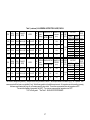
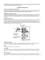
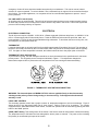
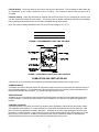
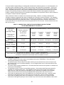
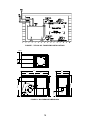
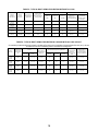
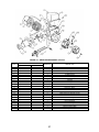
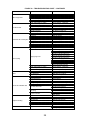
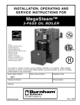
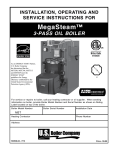
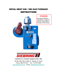
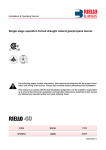
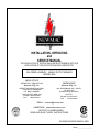
INSTALLATION, OPERATING and SERVICE MANUAL THE INSTALLATION OF THE UNIT SHALL BE IN ACCORDANCE WITH THE REGULATIONS OF THE AUTHORITIES HAVING JURISDICTION. OIL-FIRED LOWBOY - HEAVY DUTY FURNACE MODEL NL4 HEAD OFFICE MARKETING / PRODUCTION Newmac Mfg. Inc. WAREHOUSE Newmac Mfg. Inc. DEBERT AIR INDUSTRIAL PARK, LANCASTER CRESCENT P.O. BOX 9, DEBERT NOVA SCOTIA, BOM 1G0 PHONE: 902-662-3840 FAX: 902-662-2581 430 SPRINGBANK AVE., SOUTH P.O. BOX 545 WOODSTOCK, ONTARIO N4S 7Y5 PHONE: 519-539-6147 FAX: 519-539-0048 EMAIL: [email protected] HOMEPAGE: newmacfurnaces.com NOTICE TO HOMEOWNER READ AND SAVE THESE INSTRUCTIONS 156156 2210268 REVISED MARCH 2008 Printed:____________________ Table 1 - NL4 GENERAL INSTRUCTIONS - RIELLO AND BECKETT MODEL RIELLO BURNER BTUH BTUH INPUT OUTPUT (USGPH) NL4-325 40F10 326,000 377,770 (2.71) Delavan 2.25 X 60o W 145 NL4-290 40F10 293,000 335,950 (2.41) Delavan 2.00 X 60o W 145 NL4-250 40F10 256,000 292,740 (2.10) Delavan 1.75 X 60o W 145 NL4-220 40F10 222,000 252,310 (1.81) Delavan 1.50 X 60o W 145 BECKETT BTUH BTUH INPUT MODEL BURNER OUTPUT (USGPH) NM901 AFG- NOZZLE NOZZLE PUMP psi PUMP psi EXTERNAL INSERTION BURNER AIR SETTING CHIMNEY FLUE GROSS FILTER BELT DRIVE** STATIC inches PRESSURE STACK SIZE PRESSURE AIR PULLEY TURNS To Flange TURBT'R (in wc) °F (QTY) (in wc) DAMPER COMBINATION OPEN(Belt) 3-1/2" X 8" 2.5 (B49) 0.25 *9-1/2" 4 4.2 -0.04 530 0.50 3-1/2" X 8" 4 (B49) 0.25 *9-1/2" 3.5 3.4 -0.04 490 0.50 16" X 24" (4) 3-1/2" X 8" 5.5 (B48) 0.25 *9-1/2" 2.5 3.1 -0.04 430 3-1/2" X 8" 2.5 (B49) 0.50 3-12" X 8" 7 (B48) 0.25 *9-1/2" 2 2.8 -0.04 400 3-1/2" X 8" 4 (B49) 0.50 EXTERNAL STATIC PULLEY TURNS PRESSURE COMBINATION OPEN (Belt) (in wc) 3-1/2" X 8" 2.5 (B49) 0.25 0.50 3-1/2" X 8" 4.5 (B49) 0.25 0.50 16" X 24" (4) 3-1/2" X 8" 6 (B48) 0.25 3-1/2" X 8" 2.5 (B49) 0.50 3-12" X 8" 7 (B48) 0.25 3-1/2" X 8" 4 (B49) 0.50 INSERTION BURNER AIR SETTING CHIMNEY FLUE GROSS FILTER inches PRESSURE STACK SIZE To Flange SHUTTER AIR BAND (in wc) °F (QTY) NL4-305 AF104XPSS 302,000 348,500 (2.50) Delavan 2.50 X 70o B 100 9-1/2" 0 6 -0.04 520 NL4-275 AF104XPSS 272,000 313,650 (2.25) Delavan 2.25 X 70o B 100 9-1/2" 0 4 -0.04 470 NL4-245 AF104XPSS 245,000 278,800 (2.00) Delavan 2.00 X 70o B 100 9-1/2" 0 3 -0.04 420 NL4-215 AF104XPSS 215,000 243,950 (1.75) Delavan 1.75 X 70o B 100 9-1/2" 0 3 -0.04 390 BELT DRIVE** Use burner air settings as a guide only. Initially set burner air to give a trace of smoke. Then re-adjust burner air to reduce CO2 by 1 to 1.5 percent. Take measurements with the burner cover installed (if any). Select blower speed to suit installation requirements. Air temperature can be lowered by increasing the blower speed, lowering the firing rate, or increasing supply & return outlets. The minimum recommended return air temperature is 60°F. The maximum allowable air temperature rise is 85°F. The minimum recommended air temperature rise if 65°F. *9-3/8" to Riello gasket **See Table 2 - NL4 BLOWER PERFORMANCE 1 Table 1 (continued) - NL4 GENERAL INSTRUCTIONS - AERO, CARLIN AERO BURNER BTUH BTUH INPUT OUTPUT (USGPH) NL4-300 HF-US-4 302,000 348,500 (2.50) Delavan 2.50 X 70o B 100 9-1/2" - - -0.04 520 NL4-270 HF-US-4 274,000 313,650 (2.25) Delavan 2.25 X 70o B 100 9-1/2" - - -0.04 470 NL4-240 HF-US-4 246,000 278,800 (2.00) Delavan 2.00 X 70o B 100 9-1/2" - - -0.04 420 NL4-210 HF-US-4 215,000 243,950 (1.75) Delavan 1.75 X 70o B 100 9-1/2" - - -0.04 390 MODEL CARLIN BURNER BTUH BTUH INPUT OUTPUT (USGPH) NL4-295 EZ-3 301,000 348,500 (2.50) Delavan 2.50 X 70o B 100 9-1/2" 2.50 2.50 -0.04 520 NL4-265 EZ-3 271,000 313,650 (2.25) Delavan 2.25 X 70o B 100 9-1/2" 2.25 2.25 -0.04 470 NL4-235 EZ-3 242,000 278,800 (2.00) Delavan 2.00 X 70o B 100 9-1/2" 2.00 2.00 -0.04 420 NOZZLE NOZZLE PUMP psi PUMP psi EXTERNAL STATIC PULLEY TURNS PRESSURE COMBINATION OPEN (Belt) (in wc) 3-1/2" X 8" 2.5 (B49) 0.25 0.50 3-1/2" X 8" 4.5 (B49) 0.25 0.50 16" X 24" (4) 3-1/2" X 8" 6 (B48) 0.25 3-1/2" X 8" 2.5 (B49) 0.50 3-12" X 8" 7 (B48) 0.25 3-1/2" X 8" 4 (B49) 0.50 INSERTION BURNER AIR SETTING CHIMNEY FLUE GROSS FILTER inches PRESSURE STACK SIZE To Flange SHUTTER AIR BAND (in wc) °F (QTY) MODEL BELT DRIVE** EXTERNAL STATIC PULLEY TURNS PRESSURE COMBINATION OPEN (Belt) (in wc) 3-1/2" X 8" 2.5 (B49) 0.25 0.50 3-1/2" X 8" 4.5 (B49) 0.25 16" X 24" (4) 0.50 3-1/2" X 8" 6 (B48) 0.25 3-1/2" X 8" 2.5 (B49) 0.50 INSERTION BURNER AIR SETTING CHIMNEY FLUE GROSS FILTER inches PRESSURE STACK SIZE To Flange HEAD BAR AIR BAND (in wc) °F (QTY) BELT DRIVE** Use burner air settings as a guide only. Initially set burner air to give a trace of smoke. Then re-adjust burner air to reduce CO2 by 1 to 1.5 percent. Take measurements with the burner cover installed (if any). Select blower speed to suit installation requirements. Air temperature can be lowered by increasing the blower speed, lowering the firing rate, or increasing supply & return outlets. The minimum recommended return air temperature is 60°F. The maximum allowable air temperature rise is 85°F. The minimum recommended air temperature rise if 65°F. *9-3/8" to Riello gasket **See Table 2 - NL4 BLOWER PERFORMANCE 2 Table 2 - NL4 BLOWER PERFORMANCE BELT DRIVE BLOWER DELHI G15-10 BLOWER MOTOR (pulleys) 1-1/2 HP (8 x 3-1/2") DELHI G15-10 1-1/2 HP (8x 3-1/2") MOTOR PULLEY TURNS OPEN (Belt) RPM 2 (B49) STATIC PRESSURE (IN. W.C.) CFM A/C TONS 770 2,800 7 3 (B49) 740 2,600 6.5 4 (B49) 710 2,400 6 5 (B48) 670 2,200 5.5 6 (B48) 630 7 (B48) 600 2 (B49) 770 3,400 3 (B49) 740 3,100 4 (B49) 710 5 (B48) 670 6 (B48) 630 2,400 7 (B48) 600 2,300 0.50 0.25 2,800 2,600 USE ONLY TYPE B BELTS SIZE B48 OR B49 *DO NOT OPERATE THE BLOWER MOTOR PULLEY AT LESS THAN 2 TO (TURNS OPEN) AS THE BELT WILL NOT SEAT PROPERLY AND THE MOTOR MAY OVERLOAD 3 FURNACE INSTALLATION IMPORTANT Please read this entire manual and all labels before installing the furnace. Due to Newmac’s constant improvement program, specifications may change. Check with your supplier for latest information. Typical installation information is provided as an example. Ensure that the actual installation conforms to applicable codes and good practice. UNPACKING AND INSPECTION It is the responsibility of the consignee of the furnace unit to examine the packages for damage and, if found, to note the same on the Carrier’s Bill of Lading. The furnace is shipped complete with oil burner, draft regulator, air filters, and instruction manual. HEAT LOSS Before installation, verify that the furnace output capacity meets the building heat loss requirements. A detailed heat loss analysis is recommended. INSTALLATION REGULATIONS This furnace should be installed in accordance with the regulations of the authority having jurisdiction. In Canada the installation must conform to the CSA Standard B139, "The Installation Code for Oil Burning Equipment." In the United States, the National Fire Protection Association Standard NFPA 31 should be followed. Check with provincial, state, or local codes concerning clearances, venting system requirements and other regulations governing installation. Some requirements may vary from those described in this manual. FOUNDATION A dry cement pad is recommended. Ensure that the furnace is supported by a level foundation and is above any possible dampness. MINIMUM CLEARANCES TO COMBUSTIBLES NL4 One Side Rear Top Front* and Other Side Flue Pipe Floor 6” 32” 2” 24” 9” Non Combustible *Measure from panel on which burner is installed. Allow sufficient room at the front, side and rear for servicing access. 6" FOR YOUR SAFETY: Do not store or use gasoline or flammable vapors and liquids in the vicinity of this or any other appliance. VENTING PRODUCTS OF COMBUSTION - CHIMNEY The NL4 furnace should be installed on a chimney flue capable of sustaining the required minimum negative draft flue pressure of –0.04 inches of water column (ins wc). A negative over-fire pressure should be maintained. Locate the furnace as close to the chimney or flue as possible. Do not extend the flue pipe beyond the inside wall of the chimney. Refer to Table 7(a) and Table 7(b) for proper sizing and Figure 15 for optimizing chimney draft. The owner shall provide a chimney constructed to comply with the following typical code specifications: (a) The chimney must be smoke tight throughout its entire length, and must extend at least three feet (3') above a flat roof or two feet (2') above roofs within 10 feet. (b) If built of a single thickness of brick or of cement blocks, it shall be lined throughout its entire length with an approved lining, such as fire clay having not less than three-fourths inch (3/4") thickness. Fire clay lining is to be laid in mortar and made air-tight. If the chimney is of the prefabricated type, it must be an approved class "A" chimney or Type "L" Vent for interior. (c) The chimney or furnace flue must not have any other openings for attaching any fireplace, stove, range, gas or ventilating connection unless that equipment is appropriately certified. (d) If it is necessary to offset the flue, it must be done in such a manner as not to reduce the gross crosssectional area or create a ledge or obstruction, where loose material may lodge. (e) Each flue pipe connection must be secured with 3 metal screws. 4 CAUTION: Oil-fired appliances shall be connected to flues or vents having sufficient draft at all times to ensure safe and proper operation of the appliance. FURNACE CONNECTION FLUE PIPE – CHIMNEY VENT CONNECTOR Unless otherwise permitted by the installation code, use 8 inch diameter flue pipe (vent connector) to connect to the chimney. Install the flue pipe with a gradual rise of at least 1/4" per foot from the furnace to the flue. The maximum draft is obtained by keeping flue pipe elbows and pipe length to a minimum. BAROMETRIC DRAFT REGULATOR A listed/certified draft regulator must be installed in the flue pipe between the appliance and the chimney, within easy reach for adjustment and kept free from obstruction. Larger or multiple draft regulators may be used for chimneys with strong draft. Follow the manufacturer's instructions located with the draft regulator for proper installation BLOCKED VENT SWITCH The WMO-1 blocked vent control is required on Newmac oil-fired and combination furnaces or boilers installed in Canada. The WMO-1 switch must be installed on the chimney vent pipe for Newmac oil fired furnaces and boilers; and installed on the burner plate for Newmac combination wood/oil or coal/oil fired furnaces. Do not use the WMO-1 Blocked Vent Switch with the Newmac Sealed Vent System (SVS). Refer to the Newmac and Field Controls Instructions enclosed in the WMO-1 package. Wiring WMO-1 WMO-1 Limit N Primary Control T T F F Cad Cell Connect WMO-1 at appliance junction box (except CL series) Motor CL series combination furnaces: Connect WMO-1 at the burner control junction box Ignition Burner PROPER DUCT SIZING Locate the furnace as close as possible to the center of the heat distribution system and make sure the top is level. Refer to TABLES 5 and 6, DUCT SIZING FOR HEATING and COOLING in this manual. FUEL Fuel not heavier than No. 2 fuel oil must be used. FUEL TANK The oil supply tank must be of an approved type, ULC labeled in Canada and ULI labeled in the United States. Install the tank or tanks fill and vent piping according to local codes and regulations. Keep the tank at least 1/4 full. OIL SUPPLY LINE Install oil supply pipe according to local codes. If used, oil return lines, unless otherwise required by the tank listing, should be of the same diameter and extend to the same depth in the tank as the burner oil supply pipe. An 5 emergency oil shut-off valve should be installed as required by local ordinance. This can be manual, electric solenoid, or vacuum operated. To reduce vibration, form a horizontal loop in copper oil lines connected directly to the oil pump. For multiple appliances, use a separate oil line for each individual appliance to prevent “loss of prime” problems. OIL LINE SAFETY VALVE (OSV) An oil safety valve is recommended. This will only let fuel pass when the burner pump creates a partial vacuum. An OSV also prevents oil from flowing to the burner if there are any leaks in the oil line. Leaks in the system will prevent oil from flowing until they are repaired. ELECTRICAL ELECTRICAL CONNECTION The NL4 furnace requires 120/240V 19.5A 60 Hz 1-Phase supply with 20 A time delay fuses, or 120/208V 21.0A 60 Hz 1-Phase supply with 25 A time delay fuses. Follow the Electrical Code as well as provincial, state, and local regulations. Figures 9, and 10 show standard wiring schematics. To shut down the burner at any time, turn the emergency or main power switch off. THERMOSTAT Locate the thermostat on an interior wall free from drafts approximately 5 feet above floor level. The operation of the burner is normally controlled by the room thermostat, which may be set for the temperature desired, typically 70°F. If a higher or lower temperature is desired, the indicator should be set to the proper point on the scale. THERMOSTAT HEAT ANTICIPATOR To prevent short cycling, the heat anticipator should be set as recommended in the specifications for the burner primary control. This is typically set at 0.2 amps as indicated in Figure 1. This adjustment changes the thermostat’s response time to prevent the room temperature from over-running the thermostat setting. FIGURE 1 - THERMOSTAT HEAT ANTICIPATOR SETTING WARNING: The heat anticipator will BURN OUT if 25 volts are applied directly to the thermostat by shorting out the primary control during testing or incorrect wiring. If this happens the thermostat warranty is void. FAN & LIMIT CONTROL This thermally operated control has a probe to sense air temperature adjacent to the heat exchanger. Figure 3 shows the dial of the Honeywell L4064 Fan & Limit Control. Refer to Figure 2 for its settings. For controls equipped with the white Manual-Auto switch button, constant fan operation can be achieved by pushing the white button to the “MAN” position. (HIGH) LIMIT Setting: This setting shuts off the burner if the furnace outlet air temperature reaches that setting. The temperature has to fall below the limit setting before burner power is restored. The power to the circulating fan (blower) is not affected by this part of the control. 6 FAN ON Setting: The burner starts on the call for heat from the thermostat. The circulating fan starts when the air temperature in the furnace reaches the “fan on” setting. This sequence ensures that only warm air is circulated FAN OFF Setting: When the thermostat is satisfied and the burner shuts off, the circulating fan (blower) runs until the furnace has cooled off to this setting. This ensures that the blower adequately cools the heat exchanger before shutting off and keeps cooler air from being circulated through the ductwork. o Note: The minimum differential between the Fan On & Fan Off settings is 15°F (8 C). FAN ON FAN OFF LIMIT 125 90 200 FIGURE 2 - RECOMMENDED FAN & LIMIT SETTINGS FIGURE 3 - HONEYWELL L4064 FAN & LIMIT CONTROL COMBUSTION AND VENTILATION AIR A free flow of air for combustion and ventilation must be permanently provided to the furnace room. COMBUSTION AIR Combustion Air refers to the total outside air requirement required for the fuel combustion and exhaust venting of the fuel-burning appliance. This includes air for the burning the oil and air to provide chimney draft (dilution air) through the barometric draft regulator. It is provided through opening or ducts. VENTILATION AIR Ventilation air from is provided to keep the ambient air temperature around the furnace within safe limits under normal conditions. Provision should be made for free circulation of air inside the room where the appliance is located. CONFINED LOCATION A confined location is a furnace room that is too small to permit dissipation of the heat from the furnace casing. The installation code definition of a confined location is one that has less than 50 cubic feet of space per 1,000 Btu/h of input to the appliances located in that space. Ventilation in the form of wall openings or ducts must be provided to a confined location. If the furnace room has a volume greater than 50 cubic feet of space per 1,000 Btu/h of input, no provision for ventilation is necessary as the room is considered capable of absorbing and dissipating heat lost from the furnace casing without overheating the furnace room. 7 Furnaces installed in tight buildings, in buildings with unbalanced air exhaust systems, or in enclosed spaces, are very likely to have complaints of smoke, fumes, burner lockouts, and excessive fuel consumption. This is more likely in buildings constructed after 1985 due to the tighter building construction prescribed by the 1985 building codes. Regulations are specific on the minimum allowable quantities of ventilation and combustion air required. However, every building is subject to different internal and external conditions, and regulations vary among localities. Newmac requires provision for combustion and ventilation air as specified in Table 3, which is based on an analysis of relevant codes and regulations. Values indicated in Table 3 are based on the maximum input rating. However, in making combustion and ventilation analysis the aggregate input rating of all appliances in the space must be considered. The installation of additional oil-fired appliances may require more combustion and ventilation air. Allowances must also be made for the blocking effect of louvers, grilles and screens. If the design and free area is unknown, assume wood louvers have 20-25% free area and metal louvers and grilles have 60-75% free area. Screens should not be less than 1/4 inch mesh. TABLE 3 - COMBUSTION & VENTILATION AIR OPENING AND DUCT SIZING FOR NL4 MAXIMUM INPUT 378,000 BTUH Furnace room floor area (assuming 8’ height) Furnace room ventilation openings – minimum free flow area Outside combustion Air – minimum free-flow area Confined is less than 50 cu ft per 1,000 Btuh of input 1 sq in per 5,000 Btuh of input For an opening requiring 1 sq in per 1,000 Btuh of input More than 945 sq ft – unconfined 76 sq in Not required Not required Not required Not required Less than 945 sq ft - confined 76 sq in* 378 sq in 189 sq in 95 sq in 76 sq in Square 9” x 9” 22” x 22” 14” x 14” 10” x 10” 9” x 9” Round 10” Diameter 20” Diameter 16” Diameter 11” Diameter 10” Diameter Nearest Size For an opening requiring 1 sq in per 2,000 Btuh of input For an opening requiring 1 sq in per 4,000 Btuh of input For an opening requiring 1 sq in per 5,000 Btuh of input *The combustion air makeup must be from outside for all appliances. If the furnace room ventilation ducts are open to the outside, separate combustion air ducts are not required because the combustion air will be taken from the ventilation air ducts. EXPLANATION OF TABLE 3 The table is based on the furnace input for the highest nozzle rate of 378,000 Btuh. The areas can be reduced proportionately for lesser inputs. The left hand column Furnace Room Floor Area of 945 sq ft is the minimum floor area for a furnace room with a height of 8 ft for an unconfined installation. So an 8 ft high furnace room of more than 945 sq ft floor area is unconfined. The center column Outside Combustion Air – Flow Area shows the free flow area required for combustion air for the input of 378,000 Btu/h. The right hand columns Furnace room ventilation openings – flow area show the flow areas required for ventilation of a confined furnace room. The installation codes require minimum flow areas based on 1 square inch per 1,000 2,000, 4,000 and 5,000 Btu/h of input, depending on ventilation duct orientation. These areas are shown for the maximum 378,000 Btu/h NL4 input as 378, 189, 95 and 76 sq ins. If the furnace is operating at an input of 378,000 Btu/h in an unconfined furnace room, it requires outside combustion air through an opening or duct of 76 sq ins free flow area. It does not require ventilation. If the furnace is operating at an input of 378,000 Btu/h in a confined furnace room, it requires outside combustion air through an opening or duct of at least 76 sq ins free flow area, and ventilation of the furnace 8 room through additional openings or ducts either into adjacent spaces or to the outside. The codes describe give the ventilation options. The following should be kept in mind when using Table 3: All applicable codes and regulations must be followed. These give detailed requirements for combustion and ventilation air. Check the installation code to establish which ventilation rate should be applied for your duct size and orientation All furnaces require outside combustion air to make up for the air they consume through the burner and the barometric draft control. A furnace installed in an unconfined furnace room does not require specific provision for ventilation to keep it cool. For ventilating a confined space, two openings are generally required, one near the ceiling and one near the floor of the confined space. Maximum length of run for a duct with the same free flow area as the opening shown is 50 ft. Duct sizes should be increased for longer runs. Ducts carrying outside air should be designed or insulated to prevent condensation on their outer surface. A minimum insulation value of R-3 is recommended. If a grille, louver, or mesh is installed in an opening, the overall grille size must be increased so that the free flow area is maintained. The free flow area is the total amount of actual area available for the air to flow through. Ducted outside combustion air should be brought as close to the appliance as possible. The furnace is not approved for direct connection of outside combustion air to the burner, as this would defeat the operation of the barometric draft control. If a means of closing the combustion air openings is required when the appliance is not operating, such means should be interlocked with the burner to avoid unsafe operation. Guidelines to determine the need for additional combustion and ventilation air may not be adequate for every situation. If in doubt, it is advisable to err on the safe side and provide additional air. AIR CONDITIONING This appliance can accommodate air conditioning equipment. An air conditioning relay can be mounted on the furnace junction box located on the front panel. The furnace input is restricted when providing the additional static pressure for the air conditioning coil. See Table 1 - General Instructions and Table 2 - Blower Settings at the start of this manual. HUMIDIFIER If a humidifier is installed, ensure water cannot drip on the heat exchanger. This will damage the furnace and void the warranty. OIL BURNER INSTRUCTIONS BURNER CARE The burner is fully automatic in operation. A qualified technician should make all adjustments. Keep the burner free from excess dirt and moisture. Oil leaks should be tended to immediately. No lubrication is required. OIL PUMPS AND FUEL SYSTEMS Make sure the by-pass plug is correctly located for a one or two pipe system. Failure to do so may damage the pump. Generally, for 3/8” copper tubing the vertical lift should not exceed 8 feet and the horizontal run should be limited to 30 feet. Do not exceed 10 psi oil inlet line pressure to the pump. Single pipe systems are recommended for gravity feed or when the tank outlet is at a higher elevation than the pump inlet. Refer to Figure 7. The inlet vacuum, if the pump is lifting the oil, should be no more than 6" Hg. 9 Two pipe systems are recommended for lift feed or when the pump inlet is at a higher elevation than the tank outlet. Install the return line termination inside the tank higher than the supply intake as shown in Figure 7. Generally, the inlet vacuum to the oil pump should be no more than 12" Hg. Correct piping is critical to long-term operation of the fuel system. Never use compression fittings, as they may not reliably seal. Minimize the resistance to flow due to excessive line lengths; high lift; and unnecessary fittings, kinks and bends. This will decrease the running vacuum and the risk of air separation within the fuel line. A “Tigerloop” fuel oil de-aerator may improve the performance of poorly designed fuel oil delivery systems. The information presented here is intended as a guide only. For piping system design data, consult the installation instructions from the pump manufacturer. CAUTION: Do not use gasoline, crankcase or any oil containing gasoline. Do not tamper with the furnace or controls - call the serviceman. Do not attempt to start the burner when excess oil has accumulated, when the furnace is full of vapor or when the combustion chamber is very hot. Do not start the burner unless the cleanout doors are secured in place. Do not burn garbage or paper in the heating system. Never leave combustible materials such as paper or rags near the furnace. OIL BURNER INSTALLATION Install the oil nozzle in the burner firing assembly, and check the adjustments. Figure 4 and Table 4 show the correct electrode settings. These settings are important for proper burner operation. Some burner manufacturers provide a gauge available for setting the electrodes. Most burners with adjustable heads have preset stops to ensure the distance from the nozzle face to the face of the retention head (“Z” dimension) is correct. Set or check the air tube insertion depth according to Figure 6 and Table 4. This is the distance from the face of the mounting flange to the face of the retention head. Mount the oil burner on the studs of the burner plate, carefully centering it in the combustion chamber opening. Use TABLE 1 - GENERAL INSTRUCTIONS for preliminary air settings for the burner. INSTRUMENTS The installer must use a suitable draft gauge, smoke spot tester, carbon dioxide tester, 0-750°F stack thermometer, 0-200psi oil pressure gauge, 0-30 in. Hg. vacuum gauge, and 0-220°F thermometer to set-up the burner properly. OIL BURNER SET-UP 1. Turn on supply power and set the thermostat above room temperature. 2. Open all oil lines and valves. 3. Make sure the oil pump by-pass plug is correctly located for a one or two pipe system. Bleed the oil pump (refer to pump manufacturer's instructions). 4. Adjust the burner air until a #1 smoke is reached using a smoke tester. Increase the air until the CO2 level in the stack gas reduces by at least 1% below that at the #1 smoke. 5. If the burner furnace fails to start, check: (a) oil supply; (b) ignition electrodes and transformer; (c) cad cell. 6. If the burner goes off on safety, do not push the reset button on the primary control for at least 10 minutes. Do not push the reset button more than once before correcting the cause. If the burner still does not start, press the reset on the burner motor. 7. Using a suitable draft meter, adjust the barometric draft regulator to measure the specified flue pressure when the chimney is warm. This requires that a 5/16" diameter sampling hole be made between the flue collar and the draft regulator. 10 FIGURE 4 - ELECTRODE SETTINGS GAUGE PORT NOZZLE PORT INLET PORT BLEED PORT INLET PORT RETURN & BY-PASS PORT FIGURE 6 - BURNER INSERTION FIGURE 5 - TYPICAL OIL PUMP PUMP TABLE 4 - ELECTRODE AND INSERTION DIMENSIONS (See Figures 4 and 6) Riello 40F10 Beckett AFG-AF104XPSS Aero HF-US-4 Carlin EZ-3 A 5/32” 5/32" 1/8” 1/8" to 5/32" B 13/64” 7/16" 7/16” 5/16" C 5/32 to 7/32” 1/16" 1/16” flush to 1/16" Z See Turbulator Setting 1-1/8" 1-1/8” See head bar setting E 9-1/2"TF (9-3/8” to gasket) 9-1/2"TF (to flange) 9-1/2”TF (to flange) 9-1/2"TF (to flange) 11 MAINTENANCE & SERVICE Newmac requires the installer to fill out the INSTALLER INFORMATION sheet found at the end of this manual. Maintenance and servicing must be done by a qualified burner technician or shortened furnace life and poor efficiency may result. CSA B139 requires that the furnace be inspected and maintained in a safe operating condition at least annually. The heat exchanger should be inspected annually. If cleaning is required, remove the cleanout covers taking care not to damage the combustion chamber or gaskets. Use a wire brush (available from Newmac) to loosen scale and soot, and a vacuum cleaner to remove them from the furnace. Replace gaskets if necessary before replacing the cleanout covers. A layer of soot on the heat exchanger surfaces will reduce heat transfer efficiency and can increase fuel consumption. A 1/32” layer of soot acts as an insulator and can result in a 3% increase in oil burned. A 1/16” layer may result in a fuel loss of up to 8%. PRESSURE CHECK Install the pressure gauge directly on the gauge or nozzle port on the oil pump. Adjust to the pressure specified by Newmac for the nozzle input rating. Refer to TABLE 1, GENERAL INSTRUCTIONS in this manual or the certification label on the furnace. Each oil burner should have its own suction line. A common return line can be used as long as the diameter is large enough. Check valves are not required on properly installed systems. Service on the fuel pump should not be attempted without a suitable vacuum and pressure gage. OIL FILTER The oil filter should be cleaned or replaced at least once a year by the serviceperson. Use a spin-on 10 micron or better filter. Newmac recommends General Filters Model GF-CGF10 (refill GF-K10GF) or Garber Model 11BV-R. SEASONAL OR EXTENDED SHUT DOWN PERIODS When the burner is not to be used for an extended period of time, set the thermostat at its lowest value, turn off the main switch and close the burner oil supply valve. If the furnace room is damp, protect the burner against dirt and moisture with a light cover. To resume operation, remove the cover and inspect the burner. Remove any dirt and debris gently to avoid the need to adjust the air band. Open the supply valve and turn on the main switch. If the burner fails to operate see the MAINTENANCE & SERVICE section of this manual. COMBUSTION CHAMBER Make sure the combustion chamber was not damaged or misaligned during shipping. Inspect the combustion chamber periodically for damage and replace if necessary. AIR FILTERS Air filters should be inspected monthly and changed as required. At least two changes are usually required during the heating season - more may be necessary if dusty conditions exist. Remove the filter gently to prevent dust spillage. Install filters of the same size and type. When installing, check filter arrows to make sure that the airflow is passing through the filters in the correct direction. BLOWER MOTOR Motor manufacturers generally supply motors that do not require oiling. Oil ports usually have plastic covers and are found on the motor end caps. If oil ports are not incorporated, oiling is not required. For motors with provision for re-oiling use SAE 20 non-detergent oil or oil specially formulated for electric motors. Use only a few drops two or three times a year. BLOWER REMOVAL ● ● Disconnect power to the furnace before removing or servicing the blower. Remove the blower access panel on the rear of the furnace. 12 ● ● ● ● Remove the air filters and the rear filter support rails. If required, remove the belt and blower motor first. The wiring harness has sufficient length that the blower assembly can be removed without removing the blower motor or disconnecting the motor leads. Undo the four bolts securing the blower legs to the furnace floor. Slide the blower out toward the rear of the furnace. BLOWER ADJUSTMENT Do not start the burner unless the blower access door is secured in place GENERAL Depending on the oil input rate, this furnace is designed for a maximum air temperature rise through the furnace o of 85 F at a maximum external static pressure of 0.50 inches of water column (ins wc). However due to the wide range of static pressures in duct systems, it is the responsibility of the installer to verify that the temperature rise o does not exceed 85 F. See Tables 1 and 2. To measure the actual temperature rise let the furnace operate for at least five minutes. Insert a thermometer and note the temperature of the warm air supply outlet at a point at least 24 inches downstream from the plenum. Next measure the temperature at the return air plenum. The difference between these two temperatures is the rise. Increasing the blower speed, lowering the firing rate, or increasing an undersized supply and return air ductwork flow area can reduce air temperature rise. When adjusting the blower motor pulley, ensure that the current rating for the blower motor is not exceeded. The furnace life will be decreased and improper operation may result if insufficient air quantity passes over the o heat exchanger. Similarly, too much air during heating mode resulting in a temperature rise of less than 65 F may cause heat exchanger degradation due to internal condensation. ADJUSTMENT The number of turns open (TO) set on the motor pulley changes the blower speed and thus the air delivery rate (CFM) and air temperature rise. Closing the pulley (reducing the number of turns open) increases blower speed and decreases temperature rise. Opening the pulley (increasing the number of turns open) decreases the blower speed and increases the temperature rise. Do not set the motor pulley at less than 2 turns open as the current rating for the motor may be exceeded. The 8 inch diameter blower pulley is required for all applications from 0.25 to 0.5 ins wc static pressure. Correct belt tension allows a 1 inch deflection midway between the pulleys. Too much tension may overload the motor too little will cause belt slippage. Always use B type belts. When adjusting the blower motor pulley, ensure that the current rating for the blower motor is not exceeded. Recommended pulley setting combinations vary according to the fuel input and static pressure drop through the furnace and duct system. Recommended pulley combinations for heating mode are given in TABLE 1, GENERAL INSTRUCTIONS and in TABLE 2, BLOWER PERFORMANCE for airflow data. WARRANTY The following information is required to process warranty claims: Owner’s name and address; Furnace serial number; Furnace model number; Furnace installation date; Installer name, address and phone number. Newmac must issue a “Returned Goods Number” prior to acceptance of returned goods. Refer to your LIMITED LIFETIME WARRANTY for terms and conditions. Send the complete warranty information to Newmac head office by email, mail, or fax. 13 IMPORTANT HOMEOWNER INSTRUCTIONS 1. AN EMERGENCY POWER SWITCH IS REQUIRED TO BE INSTALLED IN A CONVENIENT LOCATION AT A SAFE DISTANCE FROM THE BURNER. THIS SWITCH INTERRUPTS THE ELECTRICAL SUPPLY CIRCUIT TO THE APPLIANCE. MAKE SURE YOU ARE AWARE OF ITS LOCATION AND THE OFF POSITION IS CLEARLY MARKED. 2. KEEP THE SPACE CLEAR AROUND THE APPLIANCE WITHIN THE SPECIFIED CLEARANCES TO COMBUSTIBLES. 3. ENSURE THE SUPPLY OF COMBUSTION AIR TO THE APPLIANCE IS NOT OBSTRUCTED OR CUT-OFF. 4. MAINTAIN PROPER VENTILATION OF THE APPLIANCE AREA. 5. MAINTAIN FREE AIR FLOW THROUGH THE RETURN AIR REGISTERS. * 6. CONTACT SERVICE PERSONNEL BEFORE REMODELLING. 7. CONTACT SERVICE PERSONNEL FOR ANNUAL SERVICE AND MAINTENANCE. 8. CONTACT SERVICE PERSONNEL FOR AIR FILTER REPLACEMENT. * 9. CONTACT SERVICE PERSONNEL BEFORE AND AFTER EXTENDED PERIODS OF APPLIANCE INOPERATION. 10. THE BURNER IS FULLY AUTOMATIC IN OPERATION. ALL ADJUSTMENTS SHOULD BE MADE BY A QUALIFIED TECHNICIAN. DO NOT PUSH THE RESET BUTTON MORE THAN ONCE. CAUTION : DO NOT ATTEMPT TO START THE BURNER WHEN EXCESS OIL HAS ACCUMULATED, WHEN THE APPLIANCE IS FULL OF VAPOUR, OR WHEN THE COMBUSTION CHAMBER IS VERY HOT. 11. CAUTION : DO NOT TAMPER WITH THE APPLIANCE OR CONTROLS—CALL YOUR SERVICE PERSONNEL. 12. DO NOT USE GASOLINE, CRANKCASE OIL, OR ANY OIL CONTAINING GASOLINE 13. ALWAYS KEEP THE OIL SUPPLY VALVE SHUT OFF IF THE BURNER IS SHUT DOWN FOR AN EXTENDED PERIOD OF TIME. 14. DO NOT START THE BURNER UNLESS THE BLOWER ACCESS DOOR IS SECURED IN PLACE. 15. NEVER BURN GARBAGE OR PAPER IN THE HEATING SYSTEM, AND NEVER LEAVE PAPER OR RAGS AROUND THE APPLIANCE. * FURNACES ONLY 14 NL4 - REPLACEMENT PARTS LIST NO. PART NO. 2020023 2180004 2010023 2040022 2200009 2080029 2080098 4120254 2200103 2200106 2200271 2010067 2030020 4160145 4080133 4080124 2130031 4120486G 4100117 2110101 2110053 2110026 2110179 2090054 2010008 2010057 2010048 2010041 2240008 DESCRIPTION 1-1/2 HP BELT DRIVE MOTOR (240V) 24 X 16" FILTER HONEYWELL L4064B2640B (5") FAN/LIMIT WHITE RODGERS 5D51-334 (5") FAN/LIMIT BAROMETRIC DRAFT REGULATOR 7" 110" BLOWER WIRE HARNESS CLEANOUT COVER GASKET GASKET FRONT ELECTRICAL JUNCTION BOX ELECTRICAL BOX COVER ELEC BOX COVER 4X4 SWITCH 8361 SWITCH FOR ELECTRICAL BOX DPDT 20A BLOWER POWER CONTACTOR NL4 COMBUSTION CHAMBER SIDE CLEANOUT ASSEMBLY FRONT CLEANOUT COVER FRONT CLEANOUT RETAINER CLEANOUT BRASS NUT 5/16" SIDE CLEANOUT CASING COVER 18" BURNER CABLE OIL BURNER AERO HF-US-4 OIL BURNER BECKETT AFG (NM901) OIL BURNER ONLY RIELLO 40F10 OIL BURNER CARLIN EZ-3 10" BLAST TUBE ASSEMBLY RIELLO 40F10 THERMOSTAT WR 1E30W-451S1 THERMOSTAT WHITE RODGERS IF30-349 PRIMARY RELAY HONEYWELL (BECKETT) PRIMARY RELAY HONEYWELL (AERO) PRIMARY RELAY- 530E/C (RIELLO) PRIMARY RELAY CARLIN A/C FAN CENTRE HONEYWELL R8285A VARIABLE SPEED PULLEY 3-1/2" X 5/8" 15 NO. PART NO. 2040112 4050218 4120245 4120244 4120255 4120246 4120243 4120228 4120241 4120250 4120251 4120252 4120253 4120242 4120227 3090442 4110119 4120256 4060178 4080108 2080100 4120229 4120240 2240050 DESCRIPTION DELHI G15-10 BLOWER WITH LEGS DELHI G15-10 BLOWER ASSEMBLY FRONT PANEL CENTER PANEL TOP PANEL REAR PANEL BLOWER ACCESS DOOR SIDE PANEL (LH) FAN PARTITION REAR FILTER RACK TOP FILTER RACK FILTER SUPPORT TOP RAIL CENTER PANEL FILLER BURNER PLATE BURNER PLATE SHIELD 8" SMOKE COLLAR WIRE COVER HEAT EXCHANGER ASSEMBLY 8" SMOKE PIPE SMOKE PIPE GASKET SIDE PANEL (RH) BASE PANEL B49 FAN BELT 2240009 B48 FAN BELT BLOWER PULLEY 8" X 1 2010044 RIELLO SWITCHING RELAY R8038A FIGURE 7 - TYPICAL OIL TANK PIPING INSTALLATIONS 8 3-3/4 66 30 49 1/2 50 1/2 30 10 3/4 41 1/2 30 32 FIGURE 8 - NL4 FURNACE DIMENSIONS 16 R W * power connection for burner controls with post purge (eg. Honeywell R7184B and Carlin 60200-02) T T T T F F ** connect oil line heater as Carlin instructions T T FIGURE 10 - WIRING DIAGRAM WITH FAN CENTRE FIGURE 9 - WIRING DIAGRAM HEATING ONLY 17 TABLE 5 - TYPICAL DUCT SIZING FOR HEATING WITHOUT A/C COIL Min. Number Supply Runs @ 600 FPM MINIMUM SIZE OUTPUT CAPACITY (See Table 1) Minimum Air Flow Required Supply Duct or Extended Plenum @ 800 FPM Min. Sq. Inch Needed for Spec. CFM (Total Area of All Supply Duct) 6” RUNS 80 CFM 7” RUNS 155 CFM 3-1/2 X 14” 170 CFM Return Duct Furnace or Air Handler @800 FPM Return Air Grille (or equivalent) @ Face Velocity of 500 FPM 210,000 to 230,000 2,200 CFM 30” X 16” 440 20 14 14 30” X 16” 30” X 24” 250,000 to 300,000 2,800 CFM 30” X 20” 520 24 18 16 30” X 20” 30” X 30” 310,000 to 320,000 3,200 CFM 30” X 24” 720 28 20 20 30” X 24” 30” X 36” 330,000 to 340,000 3,600 CFM 30” X 28” 840 32 24 22 30” X 28” 30” X 42” 350,000 to 380,000 4,000 CFM 30” X 36” 960 36 26 24 30” X 36” 30” X 44” TABLE 6 - TYPICAL DUCT SIZING FOR HEATING & COOLING WITH A/C COIL IN DUCT Air conditioning systems should never be sized on the basis of floor area only, but knowledge of the approximate floor area (sq. ft.) that can be cooled with a ton of air conditioning will be of assistance in avoiding errors. Size of OD Unit Normal Air Flow Required @ 400 CFM per Ton Furnace Blower Motor HP Blower Wheel DxW Supply Duct or Extended Plenum @800 FPM 7” RUNS 155 CFM 3-1/2” X 14” 170 CFM Minimum Return Air Duct Size at Furnace or Handler @ 800 FPM 14 12 20” x 20” 30” x 24” Min. Number Supply Runs @ 600 FPM 6” RUNS 80 CFM Minimum Return Air Grille Size (or equivalent) @ Face Velocity of 500 FPM 5 ton 30,000 BTUH 2,000 1-1/2 15” x 10” 20” x 20” 6 ton 72,000 BTUH 2,400 1-1/2 15” x 10” 24” x 20” 22 16 14 24” x 20” 30” x 24” 7 ton 84,000 BTUH 2,800 1-1/2 15” x 10” 24” x 24” 24 18 16 24” x 24” 30” x 30” 8 ton 96,000 BTUH 3,200 - 32” x 20” 28 22 32” x 20” 36” x 30” 18 18 20 FIGURE 11 - RIELLO BURNER MODEL 40 F10 EXPLODED ASSEMBLY FIGURE 11 - RIELLO BURNER MODEL 40 F10 EXPLODED ASSEMBLY No. Spare Part Code 1 2 3 4 5 6 7 8 9 10 11 12 13 14 15 16 17 18 19 20 21 22 23 24 25 26 27 28 29 30 3006911 3006913 3000879 3005788 3005844 3006993 3005847 3006992 3006571 3007077 3007028 C7010002 3005719 3006925 3007029 3007156 3007268 3006553 3002279 3007802 3000443 3005843 3007203 3002278 3001157 3002280 3005854 3005855 3005856 N/A Newmac Number Description No. Hydraulic Jack Capillary Tube Hydraulic Air Shutter Fan Capacitor 5.7μF Pipe Connector – return ¼” NPT/Metric Adapter – female Pipe Connector – Supply 3/8” NPT/Metric Adapter – male Crushable Metal Washer – 3/8” ID. O-Ring - Pump Pressure Regulator O-Ring Pump Cover Pump Screen Valve Stem O-Ring Valve Stem – Upper O-Ring Valve Stem - Lower Nozzle Outlet Fitting Coil U-bracket and Retainer Nut Coil Pump Pump Drive Key Motor Plate – Valve Stem Retainer Primary Control Sub-base Primary Control 530SE/C Photo Cell Semiflange (2 req’d) Universal Mounting Flange Mounting Gasket Regulator 31 32 33 34 35 36 37 5 22 40 41 42 43 44 45 46 47 48 49 50 40 41 42 43 44 45 46 47 48 49 50 19 Spare Part Code 3007317 3007223 3007205 3007209 3007234 3007087 3007357 3005798 3949071 3006978 3006966 3006965 3006979 3005888 3005890 3005869 3006981 3006983 3006984 3949072 3006978 3006966 3006965 3006980 3005889 3005891 3005869 3006982 3006983 3006984 Newmac Number Description Air Tube Cover Plate Chassis Front Plate Manual Air Shutter Air Intake Housing Burner Back Cover Crushable Metal Cover 5/8” ID. Acoustic Liner Capacitor 4μF 450V Motor 120V 60 Hz Short Combustion Head 5” (273T1) Turbulator Disc Electrode Support Nozzle Adaptor Nozzle Oil Tube – Short - 5” Regulator Assembly – 5” Electrode Assembly – 5” Electrode Porcelain Air Tube – Short – 5” End Cone Adaptor End Cone Long Combustion Head – 10” (273T2) Turbulator Disc Electrode Support Nozzle Adaptor Nozzle Oil Tube – Long Regulator Assembly - Long Electrode Assembly – Long Electrode Porcelain Air Tube – Long End Cone Adaptor End Cone FIGURE 12 - BECKETT BURNER MODEL AFG Item 1 2 3 4 6 7 9 10 11 12 13 14 15 16 17 21 48 49 ** Part number Beckett 5874GY 3709, 4198 3492, 4198, 4150 3493, 4187, 5941 3616 2139 21805U, 4189 2999 2454 A2EA 6520, 4189 2256 5636 51771U, 4217, 42922, 31232 3502 3708 5770 Description Newmac Burner Housing Assembly Air Shutter, Retaining Screws Air Band, Screw, Nut Escutcheon Plate, Screw, Plate Assembly Burner Mounting Gasket Hole Plug Motor, Mounting Screws Blower Wheel Coupling Fuel Unit, Mounting Screws Fuel Unit, Nozzle Port Fitting Connector Tube Assembly Ignition Transformer, Hinge Screws, Hold Screws Hinge To Housing Gasket Transformer Gasket Baffle (Not Used) Junction Box Kit Air Tube Combination Control Relay Honeywell R7184 Cad Cell Honeywell C544A1687T Factory Installed Air Guide - Do Not Remove From Burner 20 FIGURE 13 - AERO BURNER MODEL HF-US-4 ITEM 1 2 3 4 5 6 7 8 9 10 12 19 25 26 27 28 33 100 AERO PART NUMBER NEWMAC QUANTITY DESCRIPTION 1 1 1 1 1 1 1 1 1 1 HF-US Housing Blast Tube , 11” Mounting Flange – Fixed Flange Spacer Air Band, 9 Hole Motor 1/3HP, 3450 rpm Fan, 508-229, HF-US Coupling Pump Transformer, 2275-456 Electronic Ignitor End Cone, AFC-4 End Cone Screws, Stainless Steel Tube, Oil Delivery Blast Tube Screw (Specify Length) Slide Plate Slide Plate Locking Screw Air Band Locking Nut Oil Line Assembly Oil Burner Mounting Gasket Electrode Assembly Primary Control, 30sec CAD Cell, Honeywell, C554A1455B 1 2 1 4 1 1 1 1 1 1 1 1 21 FIGURE 14 - CARLIN BURNER MODEL EZ-3 ITEM 23135 24463 29926 31633 34439 40287 40345 44586 44842 62885 64493 66787 77438 77818 77933 82263 1 2 3 4 5 6 7 8 9 10 11 12 13 14 PART NUMBER CARLIN NEWMAC QUANTIT Y 1 1 1 1 1 1 1 1 1 1 1 see Newmac 98022 82792 56754 60200-02 40857 22996 34397 34470 75564 86322 46946 See Newmac 77942 DESCRIPTION Electrode Holding Base w/Hardware Transformer Terminal Kit (2 terminals & nuts) Elbow, 3/16 Flare x 1/8 NPT C-ring for Nozzle Line Oil Line, 3/16 OD, Oil Valve to Nozzle Line Gasket, Mounting Flange Gasket, Transformer Junction Box, 4" x 4", w/grommet and lockwasher Transformer hold-down tab - 2 req Thumb-Nut - Nozzle Line Bracket - Nozzle Line Heater Nozzle Line Heater w/electrical disconnect Flame Retention Ring Assembly Housing, w/84939 Access Cover Blower Wheel, 5/16D x 2W Thumb Screw, Head Positioning Bar 11" air tube assembly Motor, 1/7HP, 3450rpm Electrode wire - 11" Nozzle line adapter assembly, 11" Primary Control - Carlin (30-15-30) Oil Valve Fuel Unit, Suntec A2VA-7116, w/fitting Oil Line, 3/16OD, Fuel Unit to Valve Oil Line, 3/16OD, Fuel Unit to Nozzle Line Coupling for standard fuel units, approx 2-3/8" OAL: Air Band (EZ-3) Air Shutter, 4 slots (EZ-3) Newmac Head Positioning Bar Kit Combustion Head Assembly, 11" 1 2 1 4 1 1 1 1 1 1 1 1 1 1 1 1 1 1 22 FIGURE 15 – COMMON CHIMNEY DRAFT PROBLEMS 1 2 CAUSE 1 3 2 3 4 D 5 BREAKS IN CHIMNEY LINING REPAIR OR REPLACE AND RESEAL 5 CHIMNEY FLUE TOO SMALL CHECK TABLE 7 AND INSTALLATION CODE FOR MINIMUM DIAMETER D 7 8 9 10 STRAIGHTEN OR LENGTHEN REMOVE OR RELOCATE APPLIANCES IN EXCESS OF FLUE CAPACITY 14 OPENING BETWEEN FLUES PERMANENTLY SEAL OPENING 15 LOOSE FITTING CLEANOUT DOOR CLOSE AND SEAL ALL LEAKS 16 OPEN FIREPLACE SEAL OFF OPEN FIREPLACE 17 NEW MASONRY CHIMNEY WAIT 2 - 4 WEEKS FOR STRUCTURE TO CURE 18 TOO MUCH OR TOO LITTLE DRAFT ADJUST DRAFT REGULATOR TOO MUCH DRAFT WITH REGULATOR FULLY OPEN SMOKE PIPE TOO CLOSE TO CHIMNEY BASE WIDELY FLUCTUATING DRAFT AND DOWN DRAFTING INSTALL LARGER OR ADDITIONAL DRAFT REGULATORS 22 UNUSED CHIMNEY CONNECTION REMOVE AND/OR SEAL 23 HOUSE DE-PRESSURIZATION 24 FLUE PIPE TOO LONG OR TOO MANY ELBOWS 13 8 16 9 19 11 10 22 FIREPLACE 12 18 13 ASH DUMP FOR FIREPLACE 14 20 SOOT ACCUMULATION AT OFFSET REMOVE TOO MANY APPLIANCE ON SAME FLUE LOOSE SMOKE PIPE IN FLUE OPENING SMOKE PIPE EXTENDS INTO CHIMNEY FLUE 12 17 CHIMNEY OUTSIDE WALL REPAIR DAMAGE AND RESEAL DAMAGED JOIST PROTRUDES INTO CHIMNEY REMOVE JOIST AND RESTORE TO CODE STRUCTURE CLEARANCES TO COMBUSTIBLES REMOVE OR KNOCK THE OBSTRUCTION OBSTRUCTION INSIDE CHIMNEY DOWN AND REMOVE FROM LOWER FLUE CLEANOUT OFFSET IS TOO SHORT 11 7 ROOF PEAK, BUILDINGS OR TREES EXTEND CHIMNEY HEIGHT HIGHER THAN CHIMNEY ENLARGE TO CHIMNEY FLUE INSIDE COPING RESTRICTS OPENING DIMENSIONS CAP ASSEMBLY TOO SMALL FOR INSTALL LARGER CAP ASSEMBLY TO FIT CHIMNEY FLUE 4 6 6 CORRECTION 20 21 19 21 15 24 23 SECURE AND SEAL MAKE END FLUSH WITH INSIDE OF CHIMNEY FLUE RAISE SMOKE PIPE TRY DIFFERENT TYPE OF CHIMNEY CAP PROVIDE ADDITIONAL COMBUSTION AIR TO APPLIANCE MINIMIZE FLUE PIPE TOTAL EQUIVALENT LENGTH FIGURE 16 - TROUBLESHOOTING CHART PROBLEM CAUSE Thermostat Burner Motor Fails to Start Burner Start--No Flame Burner Locks out on Safety Burner Motor Overload Tripped Ceased Pump Faulty Primary Relay Oil Supply Air Leak in Oil Supply Line Oil Line Plugged or Kinked Oil Filter Clogged Loss of Prime Electrode Setting Loose or Dirty Nozzle Ignition Transformer Burner Motor Overload Trips Ceased Pump Faulty Primary Relay Cad Cell Oil Line Restricted Plugged Fuel Pump Loss of Prime Cold Oil Poor Combustion Burner Ignition Delayed Fumes & Odors From Burner Air Leak in Oil Supply Line Loose or Dirty Nozzle Faulty Oil Pump Oil Supply Line Loss of Prime Electrode Setting Cracked Electrodes Wrong Nozzle Low Oil Pressure Excess Air Faulty Transformer Insufficient Combustion Air Inadequate Flue Draft Pump Seal Leaking Loss of Prime Nozzle Assembly Adjustment Burner Adjustment Blast Tube Burned Off End Cone Wrong or Burned Off Incorrect Insertion Dirty Burner Fan Damaged Chamber Clogged Flue Passages Nozzle After Drip Unspecified Nozzle 24 CORRECTION Check for Broken Wires Tighten Connections Clean Contacts Replace Thermostat Press Rest Button Repair or Replace Repair or Replace Check Oil Supply Tighten Fittings or Replace Line Clean or Repair Replace or Clean Eliminate Teed Oil Lines Adjust Electrodes Replace Nozzle Replace Transformer Press Rest Button Repair or Replace Repair or Replace Clean or Replace Clear Restriction Clean Strainer Eliminate Teed Oil Lines Change to #1 Oil Convert to One Line System Adjust Air Settings Ensure Draft is Adequate Tighten Fittings or Replace Line Replace Nozzle Repair or Replace Pump Ensure Properly Designed Eliminate Teed Oil Lines Adjust Electrodes Replace Electrodes Use Specified Nozzle Adjust to Correct Setting Adjust Air Setting Replace Transformer Provide Combustion Air Provide Specified Draft Repair Pump Eliminate Teed Oil Lines Ensure Setting is Correct Check Using Instruments Check Blast Tube Check End Cone Measure Insertion Depth Clean Blades Check Chamber Clean Flue Passages Check Fuel Delivery System Replace Nozzle FIGURE 16 – TROUBLESHOOTING CHART – CONTINUED PROBLEM Not Enough Heat Too Much Heat Excessive Oil Consumption CAUSE CORRECTION Firing Rate Too Low Dirty Heat Exchanger Poor Combustion Undersized Capacity Distribution System Faulty Thermostat or Location Defective Primary Control Faulty Thermostat or Location Faulty Oil Pump Firing Rate Too High Oversized Capacity Distribution System Poor Combustion Excess Air Inadequate Flue Draft Insufficient Combustion Air Oil Supply Electrode Setting Wrong Nozzle Fuel System Leaking Faulty Oil Pump Over-Firing Tripping High Limit Short Cycling Noise Burner Air Tube Burn-Off Faulty Thermostat or Location Heat Anticipator Set Too Low Defective Primary Relay Burner Pump Whine Duct Expansion Plenum Amplifies Noise Blocked Flue Passages Unspecified Burner Unspecified Nozzle Incorrect Head Wrong/Misaligned Static Plate Chimney Down Drafting Poor Over-Fire Draft Over-firing Incorrect Insertion Frequent Sooting Reduced Draft Delayed Ignition Loss of Prime Unspecified Burner Unspecified Nozzle Incorrect Head Premature Corrosion Temperature Rise Too Low 25 Use Higher Input Nozzle Clean Heat Exchanger Adjust Using Instruments Sized Based on Heat Loss Proper Duct Design Repair, Replace, or Relocate Repair or Replace Repair, Replace, or Relocate Check for Proper Pressure Reduced Nozzle Size Size Based on Heat Loss Proper Duct Design Adjust Using Instruments Adjust Air Setting Provide Specified Draft Provide Combustion Air Check Oil Supply Adjust Electrodes Use Specified Nozzle Check Fuel System Repair or Replace Pump Use Specified Nozzle Size Replace Dirty Filters Increase Blower Speed Increase Undersized R/A ducts Clear Blocked Return Registers Increase Undersized S/A Ducts Clear Blocked Supply Grilles Replace Faulty Blower Motor Clean Clogged Blower Wheel Replace Broken Blower Belt Repair, Replace, or Relocate Adjust Heat Anticipator Repair or Replace Relay Eliminate Suction Air Leak Stiffen Plenum and Ducts Install Plenum Apron Clean Boiler Replace Burner Install Correct Nozzle Install Correct Head Install Correct Plate or Align Install Chimney Cap Increase Draft at Breech Correct Chimney Problems Use Specified Nozzle Use Specified Pressure Use Correct Air Tube Assembly Adjust Flange Add Combustion Air Adjust Burner Settings Eliminate Teed Oil Lines Replace Burner Install Correct Nozzle Install Correct Head Reduce Motor Speed Use Higher Specified Nozzle INSTALLER INFORMATION NAME COMPANY INSTALLATION DATE THE HOMEOWNER SHOULD TELEPHONE ( ADDITIONAL INFORMATION ) FOR SERVICE OR MODEL: Newmac NL4 - APPLIANCE INITIAL TEST INFORMATION 1 FUEL INPUT (USGPH) 2 FUEL PRESSURE (PSIG) 3 FLUE PRESSURE (INCHES WC) 4 OVERFIRE PRESSURE (INCHES WC) 5 NOZZLE ANGLE/PATTERN 6 CO2 PERCENT 7 BURNER MODEL 8 FLUE GAS TEMPERATURE (°F) 9 ROOM TEMPERATURE (°F) 10 SMOKE NUMBER (BACHARACH) 11 FUEL GRADE NUMBER 12 SUPPLY PLENUM STATIC PRESSURE (INCHES W.C.) 13 SUPPLY AIR TEMPERATURE (°F) 14 RETURN AIR TEMPERATURE (°F) 15 AIR TEMPERATURE RISE (°F) 16 LIMIT CONTROL FUNCTIONING PROPERLY 17 PRIMARY CONTROL SHUT OFF TIME (IGNITION FAILURE) 18 PRIMARY CONTROL SHUT OFF TIME (FLAME FAILURE) 26 NOTES 27 OIL FIRED FURNACE – WARRANTY Effective October 1, 2001 and subject to the following conditions Newmac Manufacturing Inc. warrants the Oil Fired Furnace, to the original owner purchaser, under normal use and repair against defects in workmanship and materials for a period of one calendar year from the date of original installation. This warranty does not cover nozzles, filters, belts etc. The burner, blower, motors, controls or any other electrical or mechanical components not manufactured by Newmac are warranted for a period of one year from date of original installation by their respective manufacturers; burners 3 years. Except as listed below, the primary heat exchanger is warranted for a period of 10 years under conditions of normal use. Under this warranty Newmac Mfg. at its option will repair or replace the heat exchanger under the above terms or offer the then current applicable retail price of a heat exchanger towards a new equivalent furnace. Proof of original purchase will be required. The warranty must be registered within 30 days of installation or the following 5 year pro-rated warranty applies. Where the furnace is installed in a greenhouse other commercial application, Newmac warrants the primary heat exchanger against defects in materials and workmanship under a 5 year pro-rated warranty subject to the conditions and exceptions listed below on a prorated basis as follows of the then current retail price 0–1 Years 100% Warranty Owner to pay 0% Of Retail Price 1–2 “ 80% Pro-rated warranty “ 20% “ 2–3 “ 60% “ “ 40% “ 3–4 “ 40% “ “ 60% “ 4–5 “ 20% “ “ 80% “ 5YEARS AND OVER “ 0% “ “ 100% “ The purchaser must pay all other costs of warranty service including labour costs involving diagnostic calls and or removing, servicing and or replacing warranty parts and or warehousing charges and or freight costs. All parts are supplied F.O.B. Debert, Nova Scotia and the defective parts must be returned freight prepaid for repair and or warranty consideration when requested by Newmac Mfg. The furnace warranty is void if the furnace is operated, installed in or exposed to an atmosphere that contains corrosive materials either air borne or otherwise. CONDITIONS This warranty refers to the primary combustion heat exchanger. In order for this warranty to be effective: 1. The furnace must be installed by a qualified licensed installer and in accordance with Newmac’s installation instructions. The furnace must also be installed in accordance with all applicable, local states, or provincial codes and the National Warm Air Heating and Air Conditioning Association Standards or generally accepted equivalent standards. 2. The furnace must operate in an environment not contaminated by halogens (such as but not limited to fluorine or chlorine) or chlorinated hydro carbons. These corrosive chemicals entering the combustion area cause rapid deterioration of inner surfaces leading to heat exchanger failures. The furnace must be maintained and cleaned on an annual basis by qualified personnel; air filters should be changed monthly. Oil filters and nozzles must be changed annually. 3. The furnace must be sized and fired correctly as stated on the label. The label must not have been defaced or removed. 4. The furnace must not be modified from its published design or purpose and or an air conditioning coil shall not be installed on the return air side of the furnace. 5. Furnace must not have been removed from the original installation site. 6. There must be adequate return air and or ductwork. 7. There must be adequate provision for combustion and ventilation air to the furnace room. 8. Warranty components may be replaced with reconditioned parts at the discretion of Newmac Mfg. 9. Proof of original purchase will be requested under this warranty. EXCEPTIONS 1. All labour, freight or diagnostic calls, removal and replacement costs and warehousing charges are the responsibility of the purchaser including the return to Debert, Nova Scotia of defective parts. 2. Defects or damages caused by failure of the refractory chamber, improper installation, wiring, electrical current characteristics, accident, misuse or abuse, fire, flood, alteration and or misapplication of the product, default or delay in performance; caused by war, government restrictions, restraints, strikes, material or freezing. 3. Refractory chamber, nozzles, air filters, belts etc... 4. Defects or damages caused by nozzle failure and/or plugging and/or oil flow restrictions due to cold oil from outside tanks or misalignment of burner at installation. 5. This warranty in no way can be considered as a guarantee of workmanship of an installer connected with the installation of the Newmac Oil Fired Furnace or as imposing on Newmac any liability of any nature for unsatisfactory performance as a result of faulty workmanship in the installation which liability is expressly disclaimed. 6. This warranty will not be applicable if the furnace is damaged or a result of being improperly serviced or operated. LIMITATIONS ON WARRANTY Newmac will make no express warranties other than the warranty set forth above. All implied warranties including the implied warranties of a merchantability and fitness for a particular purpose are limited to the duration of the express warranty, set forth above. Liabilities for incidental and consequential damages are excluded regardless of the cause. Some provinces in Canada and some states in the U.S.A. do not allow limitations on how long an implied warranty lasts so the above may not apply to you. The expressed warranties made in this warranty are exclusive and may not be altered, enlarged or changed by any distributor, dealer or any other person whatsoever. All replacement parts whether new or remanufactured, assume as their warranty period on the remaining period of this warranty. For routine service requirements contact the dealer who installed the equipment originally, or an alternate qualified and registered heating dealer or electrical. To register your warranty, please complete form below, detach and mail to Newmac Mfg. Inc. P.O. Box 9, Lancaster Crescent, Debert, N.S, B0M 1G0, Canada LIMITED LIFETIME WARRANTY REGISTRATION ____________________________________________________ ______________________________ Owner’s Name Date of Installation ____________________________________________________________________________________ Address of Installation _________________________________________ __________________________________________ Dealer’s Name Dealer’s Address _ _ _ _ _ _ _ _ _ _ _ _ _ _ _ _ _ _ _ _ _ _ _ _ _ _ _ _ _ _ _ _ _ _ _ _ _ _ _ _ _ _ _ _ _ _ _ _ _ _ __ _ _ _ _ _ _ _ _ _ _ _ _ _ _ _ _ _ _ _ _ _ _ _ _ _ _ _ _ _ _ _ Furnace Serial Number Furnace Model Number 28