1
iMPORTANT:
Read and save
these instructions,
Quick Reference
Table of Contents:
Pages
[]
Before you start
[]
EUectdcaU
requirements
[]
Product dimensions
[]
Venting requirements
mMPORTANT:
[_-
mnstaHer: Leave hstaHafion Unstrucfions with
the homeowner.
[]-[]
UnstaHafionsteps
[]-[]
Use and Care Information
Homeowner: Keep Installation hstrucfions for
future reference.
Save InstaUUationUnstructions for local eUectricaU
inspector's use.
99043793A/9763373
[]
[_-[]
Warranty
Requesting Assistance
or Service
Your safety and the safety of
others is very important.
We have provided many important
safety messagesin this manual and
on your appliance. Always read and
obey atl safety messages.
This is the safety alert symbol.
This symbol alerts you to
potential hazardsthat can kill
or hurt you and others. Ali safety
messages wiii foliow the safety alert
symbol and either the word "DANGER"
or "WARNING". These words mean:
You Ganbe killed or seri0usly injured
if you don't follow instructions.
AIi safety messages wili teli you what
the potentiai hazard is, teii you how to
reduce the chance of injury, and tell
you what can happen if the
instructions are not followed.
important:
Observe all governing
codes and ordinances.
Proper installation is your
responsibility.
Make sure you have
everything necessary for correct
installation, It is the responsibility
of
the installer to comply with the
clearances specified.
Check the location where the range
hood will be instalbd.The
location
should be away from strong draft
areas, such as windows, doors, and
strong heating vents.
Mobile home installation
The installation of this range hood
must conform to the Manufactured
Home Construction Safety
Standards, Titb 24 CFR, Part 328
(formerly the Federal Standard for
Mobile Home Construction and
Safety, Title 24, HUD, Part 280 or
when such standard is not
applicable, the Standard for
Manufactured
Home Installation
1982 (Manufactured
Home Sites,
Communities and Setups) ANSi
A225.1/NFPA 501A*, or latest edition,
or with local codes.
WARNING -- TO REDUCE THE
RiSK OF FIRE, ELECTRIC
SHOCK, OR iNJURY TO
PERSONS, OBSERVE THE
FOLLOWING:
Parts supplied:
* 2, amuminum fimters
3-I/4" x 10"(8.3x 25A era}damper/vent
connector
* parts bag
Installation work and electrical
wiring must be done by qualified
person(s) in accordance with all
applicable Codes and Standards,
including Fire Rated Construction.
Sufficient air is needed for proper
combustion and exhausting of
gases through the flue (chimney)
of fuel burning equipment to
prevent back drafting. Follow the
heating equipment
manufacturer's guideline and
safety standards such as those
published by the National Fire
Protection Association (NFPA),
and the American Society of
Heating Refrigeration and Air
Conditioning Engineers
(ASHRAE), and the local code
authorities.
When cutting or drilling into wall or
ceiling, do not damage electrical
wiring and other hidden utilities.
Ducted fans must always be
vented to the outdoors.
WARNING -- To reduce the risk
of fire, use only metal ductwork.
This unit must be grounded.
This hood is factory set for vented
installations. For non=vented
installations, purchase Charcoal
Filter Pad Kit No. 4396390 (contains
two filter pads) from your dealer.
Tools and
materials needed
for installation:
* fiat hmade
screwdriver
_ I=I/4" (3,0 am}
drill hit
pmiers
* ddH
* ruiner
• I/8" lot 3 ram} drill
hit for pilot homes
• pencil
For vented instaflations, you also need:
3=I/4"x10" (81.3 x 25A am)
® compass
or 8"
12&3 era} circme to 5" (152 am} round
tempBate
transition piece if using
round vent
metaR snips
* keyhob
® saber
saw
saw
* duet tape
6" (15.2 era) round damper
if using 5" (15,2 cml round
vent system
Cabinets with recessed bottoms:
* 2, 2" (5.8 era) wide filler strips. Length and
thickness determined by recess dimensions.
* 4 fiat head wood screws or machine screws
with washers and nuts to attach filler strips.
important: Observe all governing
codes and ordinances.
it is the customer's
responsibility:
• To contact a qualified electrical
installer.
To assure that the electrical
installation is adequate and in
conformance with National
Electrical Code, ANSI/NFPA 70
-- latest edition*, or CSA
Standards C22,1=94, Canadian
Electrical Code, Part 1 and
C22.2 No.0-M91 - latest
edition** and all local codes
and ordinances.
A separate ground wire must be
used. it is recommended that a
qualified electrician determine that
the ground path is adequate.
A 120-volt, 60-Hz, AO-only, fused
electrical system is required. A
separate 15=amp circuit is
recommended.
Do not ground to a gas pipe.
Check with a qualified electrician if
you are not sure range hood is
properly grounded.
Do not have a fuse in the neutral or
ground circuit.
IMPORTANT:
Save installation instructions for
electrical inspector's use.
The range hood must be connected
with copper wire only.
The range hood should be
connected directly to the fused
disconnect (or circuit breaker) box
through flexible armored or
nonmetallic sheathed copper cable.
A U.L.° or C.S.A.-listed strain relief
must be provided at each end of the
power supply cable. Wire sizes
(COPPER WIRE ONLY) and
connections must conform with the
rating of the appliance as specified
on the model/serial rating plate.
Wiresizesmustconformto the
requirements
of theNafionaU
EbctdcaU
CodeANSU/NFPA
70=
Uatest
edition_,or CSAStandards
C22.1=94,
Canadian
EUectricaU
Code
Part1andC22.2No.0-M91=Uatest
edition_ andaHbcaUcodesand
ordinances.
A U.L°or C.S.A.°listed
conduit
connectormustbeprovidedateach
endofthepowersupplycane(at
the rangehoodandatthejunction
box).
in U.S.only:Forpowercord
connected
installations,
a U.L°
listedrangehoodcord=connection
IdtMUSTbeused.Cordkithasnot
beenevaluatedfor usein Canada.
Copies of the standards
obtained from:
1-112"
(3,8cm}
7-1/2_
listed may be
National Fire Protection Association
One Batterymatah
Park
Quincy, Massachusetts 02269
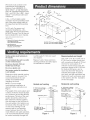
29=7/8" (75,9 am) modeh GZ8330
35=7/8" (91,1 am) modeE GZ8336
*_ CSA IntematienaU
8501 East PieasantVaHey Road
Cleveland, Ohio 44131°5575
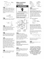
Venting system must terminate to
the outside.
roof through 6" (15.2 cm) round
vent system.
Do not terminate the vent in an attic
or other enclosed space.
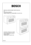
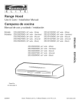
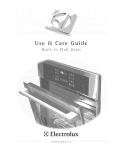
Figures 1 and 2 show, common
venting methods and what types
of materials are needed.
Do not use four4nch (10.2 am)
laundry-type wall caps.
Recommended
Do not use plastic vent.
Vent system needed for installation
is not included.
Determine which outside venting
method needs to be used. It is
recommended
that the vent
system be installed before
installing
the hood.
NOTE: if a non-vented
(recirculating)
installation is
desired, follow, instructions on
Page 5.
The length of the vent system and
number of elbow, s should be kept
to a minimum to provide efficient
performance.The
size of the vent
system should be uniform. Do
Not install two elbows together.
Use duct tape to seal all joints in
the vent system. Vent system can
terminate either through the roof
or wall. Use caulking to seal
exterior wall or roof opening
around exhaust hood. For the
most efficient and quiet operation,
it is recommended that the range
be vented vertically through the
roof
through
Use 3-1/4" x 10" (8.3 x 25.4 cm) or
6" (15.2 cm) or larger round vent
with a maximum length of 70 feet
(21.3 m) for vent system. If 7"
(17.8 cm) round vent is used, the
maximum length is 80 ft. (24.4 m).
For best performance, use no
more than three 90 ° elbows.To
calculate the length of system
you need, add the equivalent feet
(meters) for each vent piece used
in the system. See the examples
on the next page.
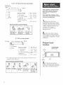
Horizontal wail venting
Verticat roof venting
5" (15,2 am) or _arger._
round or 3-1/4" x 10"
(8,3 x 25,4 am)
_-q
vent bngth
cap
8" (15.2 crn) or _arger
_-%<......
through
_._.
__
rouoa
or3-1/4"×10"
(8,3 x 25,4 crn) \
the wall "_.
roof
(8.3 x 25.4 crn)-"_
transition
piece
_-o._=$'_\
T
through
the wall
_
L
F
27"
33"
33" (83,8 am) above /
cooking
am} above
surface
L
Figure 1
:,
f/t
27" {68.6 am} to
(83.8
cap
_
(68.6
cooking
era) to
surface
/
_!
Figure 2
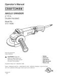
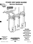
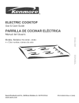
3ol/4"
× 10" 18.3 × 25.4 cm) vent system
3=1/4" × 10"
(8,3 x 2&4 cm)
e_bow
_----T
ft. ( 1,8 rn!----_
I
wall
cap
I
= 70 ft.
Maximum length
1 - 90 ° eUbow'
2 ft,
(0.6m)
8 ft. (2.4 m) straight
1 = wall cap
Length of 3=1/4" x
10" (8.3 x 25.4 cm)
system
Recommended
3=1/4" x 10"
(8,3 x 25.4 cm)
90 ° eBbow =
5 ft. (1.5 m)
:
:
:
5ft.
8ft.
Oft.
(21.3 m)
(1.5m)
(2.4m)
(Om)
= 13 ft. (3.9 m)
Cover countertop, cooktop or set-in
range with a thick, protective covering
to prevent damaging them.
l
m Disconnect
and move
freestanding range from cabinet
opening to provide easier access
to upper cabinet and rear wall. Put
a thick, protective covering over
cooktop, set=in range or
countertop to protect from
damage or dirt.
standard fittings
3=1/4" x 10"
(8.3 × 25.4 cm)
flat eRbow =
12 ft. (3.7 m)
S_ide cardboard or hardboard under
range before moving range across
floor to prevent damaging floor
covering.
3=1/4" × 10"
(8.3 x 25.4 cm)
wall cap =
0 ft. (0 m)
[] Determine which venting
method (roof or wall venting or
non=venting) you need to use.This
range hood is shipped for vented
installation.
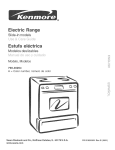
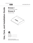
6" (15.2 cm) vent system
Prepare hood
ocation
L_
_
rvlaximum length*
1 90 ° eUbow's
=
=
1 =wall cap
8 ft. (2.4 m) straight
Length of 6"
(15.2 cm) system
_+Uf7" (17.8 cm) round vent is used, maximum
system is 80 ft. (24.4 m).
Recommended
standard
wood filler strips
(recessed cabinet
bottoms on_y}
70 ft. {21.3 m)
=
=
5 ft.
O ft.
8 ft.
(1.5 m)
(O m)
(2.4 m)
=
13 ft.
(3,9 m)
3 _r
Uength of vent
3"
/
(7,8cm!
wall
fittings
[] if cabinet has recessed
bottom, add wood filler strips on
each side. Locate screws to attach
filler strips in locations shown.
90 ° elbow =
5 ft. (1.5 m)
45 ° elbow =
2.5 ft. (0.8 m)
6" (15.2 cm)
waBI cap =
0 ft. (0 m)
3=1/4" x 10"
(8.3 x 25.4 cm) to
8" (15.2 cm) =
4.5 ft. (1.4 m)
3=1/4" x 10"
(8.3 x 25.4 cm)
loo6"
(15.2cm)
90 elbow =
511.(1.5 m)
screws
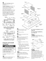
®Fromthe diagramsbelow,
sebct the diagramfor your
instaihtion.
Ventedinstallations: Cut the vent
system and electrical wiring
access holes as required. Either
wiring hole can be used.
bottom
cover
Figure 3
Non=vented installations: Cut only
the one 1=1/4" (3.2 cm) dia. wiring
access hole required, if wiring
through the top, use location
shown in VERTICAL vent systems.
If wMng through the back, use
location shown in HORIZONTAL
vent system.
6-1/4"
5-1/8"
(l&0 crn)
1-3/8"
wall
(3,5 cm)
1-1/4"
(3.2 cm) 2-1/8"
dia, ho_e (5.4 crn)
mounting
bracket
\
protective
cover
3-1/4" x 10" (8.3 x 25.4 cm)
RECTANGU LAR VERTICAL
vent system
centedine
® Remove bottom cover
screw's and bottom cover.
..
For non-vented
go to Step 13.
7m Remove filters.
® Remove wiring
and screws.
(1&1 era)
3ol/4" x 10" (8.3 x 25.4 era)
HORIZONTAL vent system
Weight Hazard
[
|
Use two or more people to move[
and install range hood.
Failure to do so can result in
back or other
njary.
For Steps 5 through
Figure 3.
10, refer to
® Set hood upside down on a
protective covering such as
cardboard or large towel.
[
vertical
vent
__b_ack
o
/
screws
knockouts
horizonta_
important: Do not grasp blower
by blower wheels. Wheels may
be damaged.
c) Lift blower
_® Depending on your
installation, remove either back or
top vent knockout.
blower wiring
b) Loosen, but do not remove,
knurbd nuts on mounting
rods. Slip rods out of blower
mounting brackets.
|
Excessive
® To make the hood lighter
and easier to install, it is
recommended that the blower
assembly be removed.
a) Disconnect
plug.
installations,
box cover
To remove:
Prepare and install
the hood
For vented installations, go to
Step 12a.
out and set aside.
0® Remove light lens.
Squeeze sides of lens toward
center to free lens tabs and lift
lens out.
1[] Depending on your
installation, remove either back or
top wiring knockout.
vent
black
screws
hinge
pln
Attach the
damper/vent connector to the
hood. Use the two black sheet
metal screws provided in the
parts bag. Note: If wall cap is
directly behind vent connector,
the dampers in the connector and
wall cap MUST NOT interfere
with each other. Remove the vent
connector damper if they
interfere.
5
keyhole
smot
front
Make electrical
b_ower
/_
bmower
disaharge
_
discharge
i
of hood
=
2[]
Electrical Shock Hazard
Disconnect power before making
electrical connections.
Failure to do so can result in
death or electrical shock.
[] Remove the 4 hood
6[]
if using direct wiring, make
sure power is disconnected, and pull
about 12" (30 cm} of wire through
wail or cabinet and into opening.
7[]
Lift range hood into final
position, feeding electrical wire
through wiring opening. Position the
range hood so that the large end of
the keyhole slots are over the
screws.Then
push the hood toward
the wail so that the screws are in the
neck of the slots.Tighten
mounting
screws to cabinet, making sure
mounting
screws are in narrow neck
of slots. Make sure that damper
blade, if used, rotates up and down
freely.
8
[] Connect
ventwork
to hood.
vertica_
vent
Reinstall blower. Do not grasp
blower by blower wheels. Position
blower so that blower discharge
lines up with damper/vent
connector and slip rods into
mounting brackets on blower
assembly.Tighten
knurled nuts
securely and reconnect blower
plug.
installations:
homes
Reinstall blower. Do not grasp
blower by blower wheels. Move
mounting rods to front holes in
hood support channels. Position
blower so that blower discharge
lines up with Iouvered opening on
hood front.
1/4"
mounting screws from the parts bag
and install in pilot holes. Leave
screw heads away from filler
strips or cabinet bottom about
1/4" (6.4 cm)
_.
Reinstall blower.
front
(64 ram)
5
i
vent
Non=vented
_.
Use 1/8" (or 3 rnm) drill bit
and drill 4 pibt hobs as shown.
I
i
Vented installations:
Connect ground wire to green
ground screw in terminal box.
drill pilot ho_e
i
•
horizonta_
I 3® Lift the range hood up
under cabinet and determine final
position. Mark on the underside
of cabinet the location of the four
keyhole mounting slots. Set
range hood aside on a protected
surface.
""
i
green or bare
ground wire
19_
Make
e_eetrica_
connector
electrical
connections.
Install Iocknut on
electrical
connector
and tighten
securely.
Connect white to white
and black to black wires using
twist=on
connectors.
Connect
green or bare ground
wire to the
green ground
screw,.
Slip rods into mounting brackets
and tighten knurled nuts securely.
Reconnect blower plug.
_ouver
cover
Remove louver cover on control
panel. Pry cover off with
screwdriver or knife.
Using a U.L.qisted power
supply cord-connection
kit
23m
(U.S. only):
(see Step 6).
Reinstall bottom
cover
Folbw Power Cord Kit instructions for
connecting wiring.
[_[] Replace wiring box cover
and screw's. Make sure that wires
are not pinched between cover
and hood.
Seal joints with duct tape to make
the secure and air tight.
lm
Install two 75 watt max.
bulbs, or one 75 watt and one 25
watt bulb for night=light use. Install
25 watt bulb in right=hand socket.
To get the most efficient
use from your new range
hood, read the "Use and
Care mnformation"
section.
Keep your Whirmpooi
mnstaHation mnstruetions and
Use and Care Guide dose
to range hood for easy
reference.
1
WARNING --To reduce the risk of
fire or electrical shock, do not use
this fan with any solid-state speed
control device.
WARNING -- TO REDUCE THE
RISK OF FIRE, ELECTRIC
SHOCK, OR INJURY TO
PERSONS, OBSERVE THE
FOLLOWING:
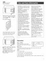
Make sure tabs are toward outside
and bottom, insert aUuminum fluter
into upper track D, push in D and
pull down _.
Non=vented installations:
Snap aUuminum fluter onto front of
charcoaU fluter. Make sure that tab
on aUuminum fluter Uines up with
finger pull on charcoaU fluter.
Use this unit only in the manner
intended by the manufacturer. If
you have questions, contact the
manufacturer. Before servicing or
cleaning unit, switch power off at
service panel and lock switch
power off at service panel and lock
service panel to prevent power
from being switched on
accidentally. When the service
disconnecting means cannot be
locked, securely fasten a prominent
warning device such as a tag to
the service panel.
CAUTION: For general ventilating
use only. Do not use to exhaust
hazardous or explosive materials
and vapors.
WARNING -- TO REDUCE THE
RISK OF A RANGE TOP GREASE
FIRE:
Never leave surface units
unattended at high settings.
Boilovers cause smoking and
greasy spillovers that may ignite.
Heat oils slowly on low or medium
settings.
Always turn hood ON when
cooking at high heat or when
cooking flaming foods.
Clean ventilating fans frequently.
Grease should not be allowed to
accumulate on fan or filter.
Use proper pan size. Always use
cookware appropriate for the size
of the surface element.
WARNING -- TO REDUCE THE
RISK OF INJURY TO PERSONS
IN THE EVENT OF A RANGE TOP
GREASE FIRE, OBSERVE THE
FOLLOWING:
SMOTHER FLAMES with a close°
fitting lid, cookie sheet, or metal
tray, then turn off the burner. BE
CAREFUL TO PREVENT BURNS.
If the flames do not go out
immediateb,, EVACUATE AND
CALL THE FIRE DEPARTMENT.
NEVER PICK UP A FLAMING PAN
--You may be burned.
DO NOT USE WATER, including
wet dishcloths or towels -- a
violent steam explosion will result.
Use an extinguisher ONLY if:
You know you have a Class ABC
extinguisher, and you already know
how to operate it.
The fire is small and contained in
the area where it is started.
The fire department is being
called.
You can fight the fire with your
back to an exit.
Blower "SPEED"
D
Push fiiter assembiy into upper track
U. Haps on fiiter will flex against top
and sides of opening. Push
assembly up until bottom of
assembly clears lip on bottom cover.
Push in D and pull assembly down
_, collapsing pull ring against
aluminum filters.
Infinite speed slide control adjusts
blower speed and sound level for quiet
operation.
Blower "ON"
ON
LIGHT
Turns blower ON and OFR When this control is turned ON, blower wiii
operate at preset speed of slide control
LIGHT
Three-position
switch.
First position (ON) - Turns both bulbs ON.
Second position - Turns right-side bulb ON.
Third position (_') - Turns both bulbs OFR
DO NOT install bulbs rated higher than 75 Watts. Install a smaller bulb on the
right for a night light.
A_uminum
meshfilters:
Removeeachfluterby grasping
the tab at the bottomof fluter,
lifting up andswingingfluterout
to the side.
Toreinstall,seeStep24a.
Charcoal
filters
Inch=vented
installations):
TheaUuminum
fluteris the onUy
washaNepart of the flutersystem.
Snapit out of its frameand
removeactrivatedcharcoaU
fluter.
CUean
aUuminum
fluterin a
detergentsoUution
of dishwater.
TheactivatedcharcoaU
fluteris not
washaMe.It shouldlastup to
twelvemonthswith normaluse.
Reassemble
filter andreinstall
filter,seeStep24b.
Whenit'stimetoreplaceyour
aluminum
fi_ter,orcharcoa_
filterpads
Inch=vented
installations):
1. FormodelseriesGZ8330and
GZ8336:
OrderAluminumFilter
No.4396389(containstwo
filters).
OrderCharcoalFilterPadKit
No.4396390(containstwo
filter pads).
2. CallWhiHpool'sTelesales
line
at 1-800-442-9991.
3. GivetheTelesales
Representative
the part
numberneeded.
4. TheRepresentative
will give
you the currentprice.
5. Placeyour orderusingyour
MasterCard:R>,
VisaRor
DiscoverRcreditcard.
6. If youwish: maila checkor
moneyorderto:
WhirlpoolCorporation
1900WhirlpoolDrive
LaPorte,IN46350-9980
Attn:AccessoryAccounting
7. Besureto asktheTelesales
Representative
aboutthe wide
varietyof otherWhirlpool
ProductAccessories.
Light lens:
Remove light lens (see Step 10).
Wash in warm, sudsy water.
Hood surfaces:
Do not allow an excessive
accumulation
of grease. Use a
mild detergent suitable for
painted surfaces. DO NOT USE
ABRASIVE CLOTH, STEELWOOL
PADS, OR SCOURING POWDERS.
Vacuum blower to clean. Do not
immerse blower in water.
WHIRLPOOLCORPORATION
MAJORAPPLIANCEWARRANTY
ONE YEAR LIMITED WARRANTY
For one year from the date of purchase, when this major appliance is operated and maintained according to instructions attached to or
furnished with the product, Whirlpool Corporation or Whirlpool Canada LP (hereafter "Whirlpool") will pay for FSP:_replacement parts
and repair labor to correct defects in materials or workmanship. Service must be provided by a Whirlpool designated service company.
ITEMS WHIRLPOOL
WILL NOT PAY FOR
1.
Service calls to correct the installation of your major appliance, to instruct you how to use your major appliance, to replace or repair
house fuses or to correct house wiring or plumbing.
2.
Service calls to repair or replace appliance light bulbs, air filters or water filters. Those consumable parts are excluded from warranty
coverage.
3.
Repairs when your major appliance is used for other than normal, single-family
4.
Damage resulting from accident, alteration, misuse, abuse, fire, flood, acts of God, improper installation, installation
accordance with electrical or plumbing codes, or use of products not approved by Whirlpool.
5.
Any food loss due to refrigerator or freezer product failures.
6.
Replacement
7.
Pickup and delivery. This major appliance is designed to be repaired in the home.
8.
Repairs to parts or systems resulting from unauthorized
9.
Expenses for travel and transportation
household
use.
not in
parts or repair labor costs for units operated outside the United States or Canada.
modifications
made to the appliance.
for product service in remote locations.
10. The removal and reinstallation of your appliance if it is installed in an inaccessible
published installation instructions.
location or is not installed in accordance
with
DISCLAIMER OF IMPLIED WARRANTIES; LIMITATION OF REMEDIES
CUSTOMER'S SOLE AND EXCLUSIVE REMEDY UNDER THIS LIMITED WARRANTY SHALL BE PRODUCT REPAIR AS PROVIDED
HEREIN. IMPLIED WARRANTIES, INCLUDING WARRANTIES OF MERCHANTABILITY OR FITNESS FOR A PARTICULAR PURPOSE,
ARE LIMITED TO ONE YEAR OR THE SHORTEST PERIOD ALLOWED BY LAW. WHIRLPOOL SHALL NOT BE LIABLE FOR
INCIDENTAL OR CONSEQUENTIAL DAMAGES. SOME STATES AND PROVINCES DO NOT ALLOW THE EXCLUSION OR LIMITATION
OF INCIDENTAL OR CONSEQUENTIAL DAMAGES, OR LIMITATIONS ON THE DURATION OF IMPLIED WARRANTIES OF
MERCHANTABILITY OR FITNESS, SO THESE EXCLUSIONS OR LIMITATIONS MAY NOT APPLY TO YOU. THIS WARRANTY GIVES
YOU SPECIFIC LEGAL RIGHTS AND YOU MAY ALSO HAVE OTHER RIGHTS, WHICH VARY FROM STATE TO STATE OR PROVINCE
TO PROVINCE.
Outside the 50 United States and Canada, this warranty does not apply. Contact your authorized Whirlpool dealer to determine if
another warranty applies.
If you need service, first see the "Troubleshooting" section of the Use & Care Guide. After checking "Troubleshooting," additional help
can be found by checking the "Assistance or Service" section or by calling Whirlpool. In the U.S.A., call 1-800-253-1301. In Canada,
call 1-800-807-6777.
8/05
if you need assistance
or service
Call the Whirlpool Customer interaction
Center toHofree at 1o800o253o1301.
Our consuitants are avaHabie to assist you.
When calling: PUease know the purchase date, and
_
of your appUiance This information w,HU
heUp us better respond to your request.
the compUete modeU and seriaU number
Our consultants provide assistance with:
® Features and specifications on our full Uine
of appUiances
® installation information
ff you need replacement
if you need to order replacement parts, we recommend that you only use factory-authorized
parts.
These parts will fit right and work right, because
they are made to the same exacting specifications
used to build every newWhirlpool
appliance.
For further
assistance
if you need further assistance, you can write to ask
any questions or tell us about your concerns at:
Customer interaction Center
c/o Correspondence
Dept.
2000 North M-63
Benton Harbor, MI 49022-2692
Please include a daytime
correspondence.
phone number
in your
in U.S.A.
® Use and maintenance
procedures
® Accessory
and repair parts sales
® Specialized
customer
assistance
(Spanish
speaking,
hearing
impaired,
limited
vision, etc.)
® Referrals to local dealers,
service companies,
and
repair parts distributors
Whirlpoolodesignated
service technicians are trained to
fulfill the product warranty and provide afterowarranty
service, anywhere in the United States.
To locate the designated
area, you can also look
Yellow Pages.
service company
in your telephone
in your
directory
parts
To locate factory-authorized
parts in your area, call
our Customer interaction Center telephone number,
your nearest authorized service center, orWhirlpool
Factory Service at 1800-442-1111.
if you need assistance
or service
1. If the probHem is not due to one of the items
Histed in "Check Operation"t_.
Contact the deaUer from whom you
purchased your appliance, or call the
Inglis Limited Consumer Assistance
Centre toIFfree,
8:30 a.m.- 6 p.m. (EST),
at 1800-235-0665.
Direct service
BRmSH
in Canada
2. if you need servicer...
Contact your nearest UngHsLimited Appliance
Service branch or designated servicing outlet to
service
your
appliance.
(See list below.)
tWhen asking for assistance or service, please
provide a detailed description of the problem,
your appliance's complete model and serial
numbers, and the purchase date.This
information will help us respond properly to
your request.
branches:
COLUMBIA
1-800-868-8788
ALBERTA
1-800-661-829!
ONTARIO
Ottawa area
1-800-267-3486
(except
Outside the Ottawa area
1-800-807-8777
807 area code)
MANITOBA, SASKATCHEWAN
and 807 area code in ONTARIO
QUEBEC
ATLANTIC
PROVINCES
For further
1-800-668-1683
Montreal (except South Shore)
South Shore Montreal
1-800-36!-3032
1-800-381-0950
Quebec City
Sherbrooke
1-800-463-! 823
1-800-567-8988
1-800-565-1598
assistance
If you need further assistance, you can write to
Inglis Limited with any questions or concerns at:
Please include a daytime phone number in your
correspondence.
Consumer Relations Department
Inglis Limited
1901 Minnesota Court
Mississauga, Ontario L5N 3A7
w'wwJ nglislimited.com
99043793A/9763373
,_ 2006 WhirJpooJ Corporation
Printed in U.S.A.
09/2005