1
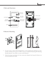
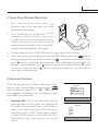
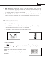
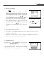
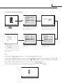
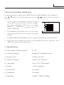
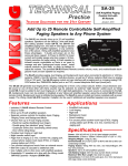
ENGLISH 2-WIRE INTERCOM SYSTEM USER MANUAL TALK MENU MONITOR DT-ENG-DT16D3AL-V1 Please read this manual carefully before using the product, and keep it well. Precautions ●● Slots or openings in the back of the monitor, are provided for ventilation and to ensure reliable operation of the video monitor or equipment and to protect if from overheating. These openings must not be blocked or covered. The monitor should never be placed near or over a radiator or heat register and should not be placed in a built-in installation such as a bookcase unless proper ventilation is provided. ●● All parts should be protected from violence vibration. And not allow be impacting, knocking and dropping. ●● For clean the LCD screen, using hands or wet cloth is forbidden. ●● Please do the cleanness with soft cotton cloth, please do not use the organic or chemical clean impregnate. If necessary, please use pure water or dilute soap water to clean the dust. ●● Image distortion may occur if the video door phone is mounted too close to magnetic field e. g. Microwaves, TV, computer etc. ●● Please keep away the video door monitor from wet, high temperature, dust, and caustic and oxidation gas in order to avoid any unpredictable damage. ●● Do NOT open the device in any condition, call the administrator for help if there is any problem or mulfunction happens. Contents 1.Parts and Functions......................................................................... 1 2.Monitor Mounting........................................................................... 1 3. Basic Door Release Operation....................................................... 2 4.Intercom Function........................................................................... 2 5.Basic Setup Instructions.................................................................. 3 5.1 How to Enter Main Menu Page................................................... 3 5.2 Ring Tone Settings....................................................................... 3 5.3 Date and Time Setting.................................................................. 4 5.4 Slave Address and Guard Unit..................................................... 4 5.5 Restore to Default........................................................................ 4 5.6 Unlock Parameter Setting............................................................ 5 6.Screen and Volume Adjustment...................................................... 6 7. Specifications................................................................................. 6 The model you purchased may not have all the functions mentioned here, but the operation is similar. 1 1.Parts and Functions Microphone LCD Screen Mounting Hook LED Indicator CALL Button UNLOCK Button Connection Port TALK Button TALK MENU MENU Button MONITOR ON MONITOR Button 123456 Extend Port DIP Switches Direction Button Speaker 145~160 cm 2.Monitor Mounting 1. Use the screws to fix the Mounting Bracket on the mounting box.(fitting accesories includes a Bracket (Two pieces of 4X25 screws are needed for fastening the Mounting Bracket), Special 2 wire cables to connect with Monitor) 2. Wire the system correctly(see the later connection chapter) then hang the Monitor on the Mounting Bracket firmly. 2 3. Basic Door Release Operation 1. Press CALL button on outdoor station , the Monitor rings, at the same time, the screen displays the visitor image. 2. Press TALK Button on monitor, you can communicate hands free with the visitor for 90 seconds.After finishing communication,press "TALK" button again to end the communication. If nobody answers the phone, the screen will be turned off automatically after 40 seconds. 3. During talking state, Press UNLOCK Button to open the door for the visitor. 4. When the monitor is in standby mode, press MONITOR Button(or select item on main menu page), The screen will show the icon , if multi door stations are installed. press ▲ button to choose the first camera,the screen will display the image from the first door camera.Similarly, Press button to choose the second one,Press ▼ button to choose the third one, Press button to choose the fourth one. Press"MONITOR" 1 4 2 3 button again to end monitoring. 4.Intercom Function When the monitor is in standby mode, press CALL Button to enter Intercom Function page(or select item on main menu page). Use ▲ / ▼ Button to move upward / downward to select the item you want, press MENU Button to enter. 1. Intercom Call: User in one apartment can call other apartments in the system. the namelist will be created automatically by the system. Selete a name on the screen then press CALL Button to call.(Note:1. Press "CALL" button again to redial. 2. Press "TALK" button to cancel the call. 3.The DIP switches code of the monitors are not the same.) Intercom Function Intercom Call Inner Call Direct Dial Guard Unit Exit - Name List [01] Mr A [02] Mr B [03] Mr C [04] Mr D [05] Mr E 3 2. Inner Call: If multi Monitors are installed in the same apartment, select Inner Call, all the other Monitors will ring at the same time, whichever Monitor answers the call, conversation is started.and the other monitors will stop ringing at the same time.(note:the DIP switches setting of all monitors must be same. ) 3. Direct Dial Guard unit: A Monitor can be assigned as Guard Unit Monitor; when the Guard Unit Monitor answers the call, conversation with the guard person is started.. 5.Basic Setup Instructions 5.1 How to Enter Main Menu Page 1. Press MENU Button in standby mode, the date/time page will be showed. (the date/time page will be closed in 3 munite if no operation) 2. Press MENU Button again, main menu page will be showed. 5.2 Ring Tone Settings Select item on main menu page to enter setup page.There are 12 pieces ring tones can be selected.use / Button to select last/next ring tone,it will perform immediatelly. setup Outdoor Tone :set the ring tone calling from outdoor Outdoor Tone -- 01 station. Intercom Tone -- 05 Monitor Time Intercom Tone :set the ring tone calling from other apartments. -- 1min Advanced Set... Auto Record Exit -- OFF 4 5.3 Date and Time Setting 1. Select item on main menu page to enter setup page,then use ▲ / ▼ button to select Advanced set... item. A password will be asked before enter next sub menu.the password is 2008, use ▲ / ▼ Button to increase / decrease the value; use / Button to select last/next digital. After inputing,press MENU Button to confirm and enter the sub menu page. setup 2. Select Date and Time Set... item. Input date and time by pressing the ▲ / ▼ Button to increase / decrease the value and / Button to select last/ next digital,After finishing,press MENU Button to confirm. Slave Addr Set -- 0 Guard Unit Set -- 0 Date/Time Set... Other Settings... Information... Exit Time 1 0 : 3 2 Date 2 0 1 0 0 3 3 1 5.4 Slave Address and Guard Unit 1. According to 5.3. The Slave Addr Set item is for the master and slave user code setting, it is set by installer. 2. Guard Unit Set: if the item is set to 1, the Monitor is assigned as a Guard Unit Monitor, for normal users, it should be set to 0. 5.5 Restore to Default According to 5.3 , select Information... item, this item will show the hardware/software version and voltage information of the Monitor. Select Restore to default item ,then press MENU button. All settings will be restored to default.(Note that the restore to default operation will not change the time setting and the datas.) Hardware ver 0302 Software ver 0168 Voltage 22.4V Manufacture 00.0T Restore to default Exit 5 5.6 Unlock Parameter Setting Outdoor Tone -- 01 monitor Intercom Tone -- 05 intercom Monitor Time -- 1min Advanced Set... setup Auto Record exit -- Password: 0 *** OFF Exit 1.Press setup item on main menu page. Unlock Time 3 Unlock Mode 0 Unlock Menu 1 Exit 2.Select Advanced Set...item and 3.The default password is 2008. press MENU button to enter,a After finishing,press MENU password will be asked. button to enter next sub menu. Hardware ver 0302 Slave Addr Set -- 0 Software ver 0168 Guard Unit Set -- 0 Voltage 22.4V Date/Time Set... Manufacture 00.0T Other Settings... Restore to default Information... Exit Exit 6.Use ▲ / ▼ button to select the 5.Press UNLOCK button and 4.Select Information...item and item, use hold for 2s. press MENU button. / Button to decrease / increase the value of the item.settings will be performed immediatelly.select Exit item to exit. Note: 1.When the Unlock Menu is set to 1, you can only release one lock. 2.When the Unlock Menu is set to 0, you can release two locks.at this mode,press UNLOCK button,two unlock icons will be showed. Use ▲ / ▼ button to select the item you want, and press UNLOCK or MENU button to release the corresponding door. 3.The restore to default operation will not change the Unlock Menu setting. 1 2 6 6.Screen and Volume Adjustment During monitoring or talking, press MENU Button,the ADJUST MENU will be displayed. Use ▲ / ▼ Button to select the adjustment item; use / Button to decrease / increase the value. 1. The first item is Scene mode selection: Total 4 screen modes can be selected in sequence: Normal, User, Soft and Bright. Whenever you modify Brightness or colour, Scene item will be set to User mode automatically. user scene 5 Brightness RGB 2. The Brightness and Colour item is for the image quality setting, adjust the value to get the best image you like. 4 Colour 2 Ring Volume 6 Talk Volume 3. The Ring Volume and Talk Volume items are ring tone and talking volume adjustment. 4. Note that all the modifications will be done immediately after the operation. Press "MENU" button to quit the adjust page. 7. Specifications ●● Power supply for indoor monitor: DC 24V ●● Power consumption: Standby 2W; Working status 5W ●● Monitor screen: 3.5 Inch color LCD ●● Display Resolutions: 320(R, G, B) x 240 pixels ●● Video signal: 1Vp-p, 75Ω, CCIR standard ●● Wiring: 2 wires, nonpolarity ●● Monitor time: 40 seconds ●● Talking time: 90 seconds ●● Dimensions: 220(H)×105(W)×20(D)mm 7 Note The design and specifications can be changed without notice to the user. Right to interpret and copyright of this manual are preserved. DT-ENG-DT16D3AL-V1