1
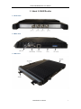
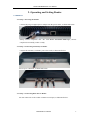
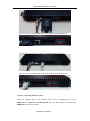
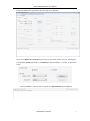
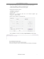
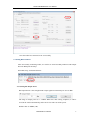
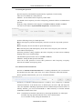
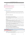
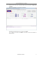
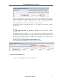
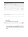
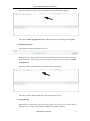
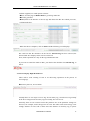
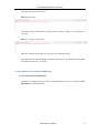
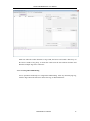
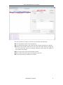
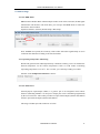
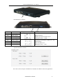
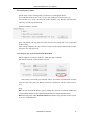
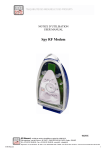
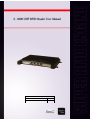
Scope of Document
Firmware Release of Reader
V 6.9
Version of Demo
V 3.62
S-8600 UHF RFID Reader User Manual
Table of Contents
1. About S-8600 Reader........................................................................................................... 3
1.1 Front View .......................................................................................................................... 3
1.2 Back View ........................................................................................................................... 3
1.3 Side View ............................................................................................................................ 3
2. Operating and Setting Reader ............................................................................................ 4
2.1 Initial Use ........................................................................................................................... 4
2.1.1 Step 1: Powering the Reader ............................................................................................ 4
2.1.2 Step 2: Connecting Antenna(s) to Reader......................................................................... 4
2.1.3 Step 3: Connecting Data Line to Reader .......................................................................... 4
2.1.4 Step 4: Operating Reader via Demo ................................................................................. 5
2.2 Setting RF Parameter ........................................................................................................ 8
2.2.1 Setting RF Output Power.................................................................................................. 8
2.2.2 Setting RF Spectrum......................................................................................................... 9
2.2.3 Antenna Connection Detector........................................................................................... 9
2.2.4 Measure RF Port Return Loss ........................................................................................ 10
2.3 ISO-18000-6C tag inventory ........................................................................................... 10
2.3.1 Real Time Mode & Buffer Mode ................................................................................... 10
2.3.2 Users define Session ID & Inventorying Parameter of Inventoried Flag ....................... 13
2.3.2 Fast Switching Antenna to Inventory Tags ..................................................................... 13
2.4 Accessing ISO-18000-6C Tag .......................................................................................... 14
2.4.1 Read tag operation .......................................................................................................... 15
2.4.2 Write Tag Operation ....................................................................................................... 16
2.4.3 Lock Tag Operation ........................................................................................................ 16
2.4.4 Kill Tag Operation .......................................................................................................... 17
2.4.5 Tag Selection .................................................................................................................. 17
2.4.6 Error Display Might Be Returned .................................................................................. 18
2.5 Accessing & Inventorying ISO-18000-6B Tag ............................................................... 19
2.5.1 Inventorying ISO-18000-6B Tag .................................................................................... 19
2.5.2 Accessing ISO-18000-6B Tag ........................................................................................ 20
2.6 Other Settings .................................................................................................................. 22
2.6.1 Set DRM Status .............................................................................................................. 22
2.6.2 Operating Temperature Monitoring ................................................................................ 22
2.6.3 Set GPIO Level .............................................................................................................. 22
2.6.4 Setting Buzzer Status ...................................................................................................... 24
2.6.5 Charging The Serial Communication Baud Rate ........................................................... 24
3. Develop your own RFID Application ............................................................................... 25
UHF RFID User Manual
2
S-8600 UHF RFID Reader User Manual
1. About S-8600 Reader
1.1 Front View
1.2 Back View
1.3 Side View
UHF RFID User Manual
3
S-8600 UHF RFID Reader User Manual
2. Operating and Setting Reader
2.1 Initial Use
2.1.1 Step 1: Powering the Reader
Connect the plug of supplied power adapter into the power outlet, as illustrated below:
Startup normal completion after “Di” with Power and Status LED light, self-test
completed successfully, reader is ready.
2.1.2 Step 2: Connecting Antenna(s) to Reader
Connect the antenna(s) with TNC port to the reader, as illustrated below:
Access up to 4 antennas, as illustrated below:
2.1.3 Step 3: Connecting Data Line to Reader
You can connect PC to the reader via RS-232 serial port, as illustrated below:
UHF RFID User Manual
4
S-8600 UHF RFID Reader User Manual
Then, you need to switch the DIP switch to the position as illustrated below:
You can also connect PC to the reader via TCP/IP, as illustrated below:
Then, you need to switch the DIP switch to the position as illustrated below:
2.1.4 Step 4: Operating Reader via Demo
Launch the supplied Demo. This software don’t need to installation. Just put the
UHFDemo.exe, reader.dll, customControl.dll into the same folder, and double-click
UHFDemo.exe to run the software.
UHF RFID User Manual
5
S-8600 UHF RFID Reader User Manual
Launch the UHF Demo application, the following screen displays:
Please select RS232 in Connection if the reader is connected via RS -232 port. Selecting the
corresponding Serial Port number and Baudrate, default baudrate is 115200. As illustrated
below:
Click on Connect , if the port isn’t occupied, the Operation History will displays:
UHF RFID User Manual
6
S-8600 UHF RFID Reader User Manual
If the reader is connected via TCP/IP, you need to operate these following steps,:
1. Ensure that an Ethernet Card has been installed in the PC.
2. Ensure that PC and reader in the same network segment.
Default settings of Reader as follows:
1. IP addresses: 192.168.0.178
2. Net mask: 255.255.255.0
3. Port No.: 4001
Detailed TCP / IP configuration, please refer to the document supplied:\ tcpip
configuration \ IPORT-1UM.PDF
Initial use, please configure it as illustrated below:
Click on Connect, if it connect successfully, the Operation history column displays:
Text communication with the reader:
Click on the button below the position shown in figure.
Click on Get in Firmware Version or in Reader Identifier, the following screen displays:
UHF RFID User Manual
7
S-8600 UHF RFID Reader User Manual
Now the reader has connected to PC successfully.
2.2 Setting RF Parameter
After successfully connecting reader, we need to set some basic RF parameters: RF Output
Power & RF Spectrum Setup.
Select RF setup, as illustrated below:
2.2.1 Setting RF Output Power
RF Output Power is the strength of RF output signal from antenna port. Unit is dBm.
The range of output power is 0 - 33dBm. When this value setting completes, it will be
saved in the reader automatically, and won’t be lost after cut off the power.
Default value is 30dBm (1W).
UHF RFID User Manual
8
S-8600 UHF RFID Reader User Manual
2.2.2 Setting RF Spectrum
Specific frequency and channel usage dictated by regulations of each country
There are two methods to set RF spectrum.
Method 1: Use the default carrier frequency of the reader.
The default carrier frequency can refer to Frequency parameter tablet in Communication
protocol.
Frequency range which the reader supports is 865MHz-868MHz, 902MHz -928MHz.
You can set the reader in System Default Frequencies, as illustrate below:
Note the following when you set RF Spectrum:
◆The start frequency and the end frequency must not exceed the scope of RF spectrum
norm.
◆Start frequency must be less than or equal end frequency.
◆Set start frequency and end frequency to the same carrier frequency, the reader will
work under fixed-frequency.
When the parameter setting completes, RF carrier frequency of reader will be randomly
hopping in the scope of limited range.
The default RF spectrum norm is FCC (902MHz-928MHz).
Method 2: Setting the RF spectrum manually.
Users can set RF spectrum via these three parameters: Start Frequency, Frequency
Interval, The number of Frequency points.
2.2.3 Antenna Connection Detector
Function of Antenna Connection Detector is: Checking whether the port is connected to
the antenna before the reader work. If not, users will be notified to connect the antenna.
Please open this function before you use it, as illustrated bellow:
Sensitivity of Antenna Connection Detector is setted by users. Sensitivity of Antenna
Connection Detector is the Return Loss of antenna port, the unit is dB. The larger the
value, the impedance matching requirements between antenna and port must be better. To
ordinary antennas, you can set the threshold to 3-6dB. Sensitivity of Ceramic Antenna
and Handset could be more lower.
Note: 1. Reader detects antenna connections by measuring the Return Loss of RF ports.
2. Reader stops tag operation if Return Loss is above the threshold.
3. User can turn it off by setting the threshold to 0.
UHF RFID User Manual
9
S-8600 UHF RFID Reader User Manual
If antenna is not connected, Reader will stop to operate tags with the following screen
display:
2.2.4 Measure RF Port Return Loss
2.3 ISO-18000-6C tag inventory
Connect the Reader correctly. Tag operation could be started when RF Setup completes.
Tag inventory means identify multiple tags’ EPC number at the same time. This is the
core of UHF RFID Reader whose performance will directly determine the merits of the
reader.
2.3.1 Real Time Mode & Buffer Mode
There are many modes to select for tag inventory.
The most commonly used mode is Real time mode. Data will be uploaded immediately
and you can find the tags’ EPC number at the first time.
The other is Buffer Mode, the data will be cached firstly and uploaded together when you
need them.
Both models have their own characteristics. Advantages of real-time mode are good
multi-tag identification performance and fast response, users could get the data without
delay. RSSI and Parameter of Frequency are change in real time, too.
Reader uses a dual CPU architecture, Identify Tags and Data Transmission are in the
charge of two different CPU, they are not interfere with each other. So you don’t worry
about data transfer will reduce the performance of multi-tag identification. Performance
of multi-tag identification under Real Time Mode is the best.
Advantage of Buffer mode is the small amount of data communication, because the
aggregated data is uploaded filtered and no repeat. But it will take some time to filter
duplicate data when reader identifies a large number of tags. Therefore, its identification
efficiency will be slightly lower than Real time mode.
Note, tags can’t be operated when you extract data in the cache.
Users can choose the appropriate method based on actual situation.
In Demo supplied, you can choose these methods to Inventory Tag as illustrated below:
Let’s inventory tags under Real Time Mode first.
Click on Tag Inventory (Real Time Mode). Select the checkbox for the port with a
UHF RFID User Manual
10
S-8600 UHF RFID Reader User Manual
connected antenna. Set the number of Repeat per command. This number is the times of
repeat inventory command. For example, per inventory command will execute
anti-collision algorithm one time when you set the value to 1. It will execute anti-collision
algorithm two times when you set the value to 2, and so on.
Next, click on Inventory, we can find that the EPC number is uploaded immediately and
real time update. If you do not click on Stop, the reader will keep inventorying. As shown
below:
Meaning of the data as shown below:
Total of inventory Tags
Identification Speed
Cumulative return data
Command execution
time
Total running time
Total number of inventory tags since click on Inventory Tag.
Speed of identification Tag, unit: piece / sec
Total return EPC data of tags (Including repeated reading of data)
Time of each Inventory Command takes, unit: ms
Total elapsed time since click on Inventory Tag, unit: ms.
Meaning of the data in Tag list as shown below:
ID
EPC
PC
Identification Times
The serial number of data.
EPC number of tag.
Protocol Control word of tag.
Times of tag identified.
RSSI
The signal strength when tag was identified at the last time.
Carrier Frequency
Carrier Frequency of tag which is identified at the last time.
Next we will inventory tag under Buffer Mode.
The same as Real Time Mode, click on Tag Inventory (Buffer Mode). Then, select the
UHF RFID User Manual
11
S-8600 UHF RFID Reader User Manual
checkbox for the port with a connected antenna and set the number of Repeat Per
Command.
Then click on Inventory, the following screen displays:
We find that the identified tags won’t be shown in the Tag list.
Click on Stop first, then click on Get Buffer. All the data in cache will be uploaded, as
illustrated below:
UHF RFID User Manual
12
S-8600 UHF RFID Reader User Manual
Functions of other three cache operation buttons described as follows:
Get and Clear: Read the data form cache and then clear the cache. It will be empty when
you read the cache again.
Query tag Quantity: If you just want to know there are how many tags in cache without
details, click on this button.
Clear Buffer: Clear the cache and refresh the screen.
Users could find the difference between Real Time Mode and Buffer Mode through the
above operation.
2.3.2 Users define Session ID & Inventorying Parameter of Inventoried Flag
2.3.2 Fast Switching Antenna to Inventory Tags
In the standard operation of inventory tag (Real Time Mode & Buffer Mode), the process
of each time inventory will takes at least 500-800ms. Only when inventory completed,
reader can respond to the other new command.
In many case, however, 500-800ms is not be accepted. Then Fast Switch Antenna Mode
will be used.
There are two methods can achieve fast switching antenna.
Method 1:
Set the value of Repeat Per Command to 255 (0xFF)
As illustrated below:
UHF RFID User Manual
13
S-8600 UHF RFID Reader User Manual
Then click on Inventory. At the moment, operating time of each round inventory will be
as short as possible. Generally speaking, if only 1 or 2 tags in RF region, it will takes
50ms to finish the inventory before the reader receive new command. The
time-consuming will be longer when the number of tags increasing.
For specific format of command parameter, see the reader's serial interface protocol
version V2.35.
Method 2:
Use cmd_name_fast_switch_ant_inventory command (see serial interface protocol
version V2.35).
The difference between method 1 and 2 is: the process of sending switch antenna
command is omitted in method 2, so it is faster and more efficient. It takes 25ms to read
one tag form one antenna. For specific method of this command, see the reader's serial
interface protocol version V2.35.
We can see the effect of Fast Switch Antenna Mode in demo.
Select Fast switch Antenna Mode, the following screen displays:
2.4 Accessing ISO-18000-6C Tag
Click on Access Tag, the following screen displays:
UHF RFID User Manual
14
S-8600 UHF RFID Reader User Manual
The following describes how to read or write the tags.
2.4.1 Read tag operation
You can type the parameter in the interface as illustrated below:
To read tags, you need to input three parameters: Area of Tag, Start Address and Data
Length.
Note, the unit of Starting Address and Data Length is WORD which is 16 bit double-byte.
Click on Inventory, when the parameter setting completes.
Note, the parameters you input must meet the specification of the tag, or an error message
will appear.
When the operation completes successfully, the following screen displays:
UHF RFID User Manual
15
S-8600 UHF RFID Reader User Manual
In the above image, it says two tags have been identified successfully.
2.4.2 Write Tag Operation
The area of Write Tag is the same as Read Tag, but you need to provide access password
and information of write data extra.
When you operate successfully, the following screen displays:
How many tags operated successfully, the equal of pieces data will be displayed in Tag
List. It is blank in Data and this is the difference from Read Tag. The user can read the
tag again in the same area to verify if the data was written correctly.
Note: The maximum length of one-time write is 32 Word (64 bytes, 512bits).
2.4.3 Lock Tag Operation
The interface of Lock Tag Operation as below:
A password must be provided if you want to Lock Tag.
UHF RFID User Manual
16
S-8600 UHF RFID Reader User Manual
When the operation completes successfully, the following information displays:
The same as Write Tag Operation, data of identified tags will be displayed in Tag List.
2.4.4 Kill Tag Operation
The interface of Kill Tag Operation as below:
Kill Tag must provide a destruction password and the destruction password can’t be 00 00
00 00. Therefore, to kill a tag, you must change the content of password area via Write
Tag Operation.
When tag is killed successfully, the following information displays:
The same as above, data of killed tags will be displayed in Tag List.
2.4.5 Tag Selection
Many times, no matter how many tags in RF region, we just want to access the known
EPC tag. Now, we can use the function of Tag Selection (EPC matching).
UHF RFID User Manual
17
S-8600 UHF RFID Reader User Manual
In demo supplied, we could operate as below:
◆First, inventory tags in Buffer Mode to get all tags’ EPC NO.
◆Second, get buffer.
◆Third, back to the interface of Access tags and choose the EPC NO. which you want ,
as illustrated below:
When the choose completes, click on Select and the following screen displays:
We could see that the checkbox on the left for Selected Tag has been selected, the
Selected EPC NO. displays in the text box on the left.
Next, all the operations are only for the tag with this EPC NO.
If you want to cancel the match of EPC, just deselect the checkbox for Selected Tag, as
below:
2.4.6 Error Display Might Be Returned
There will be some warning of error if we did wrong operations in the process of
accessing tags.
◆Inventory Success, access failure:
Actually there are two-steps to access tag: first inventory tag, second access tag. Prompt
in the above image means inventory tag successfully, but can’t access.
Generally, there are two reasons lead to this problem. One is the parameter settings are
incorrect, for example, read a storage area not exist. The other reason is RF energy is not
enough, distance of access tab is about 60%-70% distance of inventory tag, so please
UHF RFID User Manual
18
S-8600 UHF RFID Reader User Manual
move the tag closer to the antenna.
◆Wrong password:
The reason causing this problem, as the prompt in the above image, is set wrong access
password.
◆There is no tag to be operated:
The above warning means there is no tag to be operated in RF region.
The significance of other information returned, users can see the document: UHF_RFID
serial interface protocol _V2.38.pdf.
2.5 Accessing & Inventorying ISO-18000-6B Tag
2.5.1 Inventorying ISO-18000-6B Tag
Operating ISO-18000-6B Tag is similar to ISO-18000-6C but easier. It only have Real
Time Mode, as illustrated below:
UHF RFID User Manual
19
S-8600 UHF RFID Reader User Manual
Each time when the reader identifies a Tag’s UID, the buzzer will sound a short beep. If
the buzzer sounds a long beep, it means the reader start the anti-collision function and
identifies multiple tags at the same time.
2.5.2 Accessing ISO-18000-6B Tag
Access operation could only for a single ISO-18000-6B tag. After stop Inventorying Tag,
click the Tag UID on the left list to choose the Tag, as illustrated below:
UHF RFID User Manual
20
S-8600 UHF RFID Reader User Manual
The next operation are simple, you can do it yourself. Note the following:
◆Access operation just only for the selected tag.
◆It can read multi-byte data of tag at the same time, length of the data is not limited.
◆Multi-byte data could be witten. If an error occurs, the reader will stop writing, but
has been written data will not be changed, while the reader returns the number of
bytes written successfully.
◆Only one Byte data of tag can be locked at one time.
◆Only one Byte data state of tag can be inquired at one time.
◆Lock byte operation is permanent, irreversible.
UHF RFID User Manual
21
S-8600 UHF RFID Reader User Manual
2.6 Other Settings
2.6.1 Set DRM Status
DRM is Dense Reader Mode. When multiple readers work at the same time, the RF signal
transmission will interfere with each other, you can open the DRM mode to reduce the
interference between them.
Operation interface as below (Reader Setup->RF Setup):
Note: If DRM was opened, the sensitivity of the reader will reduce significantly. So users
could start this function according to the actual situation.
2.6.2 Operating Temperature Monitoring
Reader will generate heat under high intensity continuous working. Users can monitor the
internal temperature via the built-in temperature sensor to avoid reader overheating
(Operating temperature over 65℃). If it’s too hot, you could stop reading for a while.
Interface of the Temperature Monitor as below:
2.6.3 Set GPIO Level
General-purpose input/output (GPIO) is a generic pin on an integrated circuit whose
behavior (including whether it is an input or output pin) can be controlled (programmed)
by the user at run time. This reader provides two opto-isolated inputs (GPIO1 and GPIO2)
and two opto-isolated outputs (GPIO3 and GPIO4).
The image of GPIO port with connector as below:
UHF RFID User Manual
22
S-8600 UHF RFID Reader User Manual
PIN definitions as follows:
PIN ID
Function
PIN 1
GPIO 1 Input +
PIN 2
GPIO 1 Input -
PIN 3
GPIO 2 Input +
PIN 4
GPIO 2 Input -
PIN 5
GPIO 4 Output
PIN 6
GPIO 4 Output
PIN 7
GPIO 3 Output
PIN 8
GPIO 3 Output
Equivalent Circuit
Instructions
◆Voltage between PIN 1,2 (PIN 3,4) <=12V
◆Heteropolarity
◆LED equivalent resistance 470Ω
◆Response time<= 150uS
◆Voltage between PIN 5,6 (PIN 7,8)<=12V
◆Nonpolarity
◆On resistance110Ω
◆Response time <= 6mS
Operation interface as below:
Users can use the serial port commander to read and write GPIO in their own applications
UHF RFID User Manual
23
S-8600 UHF RFID Reader User Manual
2.6.4 Setting Buzzer Status
Sound of the reader’s working status provided to users through the Buzzer.
Users can turn off the buzzer or set it “beep” after each time reader inventory tag.
You can also set it “beep” afer each time reader identifies a tag. But this will reduce the
efficiency of multi-tag identification.
Operation interface as below:
Note: The Buzzer will ring when Power On Self Test successfully and it is not controlled
by this setting.
After setting completes, the state of buzzer will be saved in the FLASH inside of reader
and won’t lose after power cut.
2.6.5 Charging The Serial Communication Baud Rate
Reader supports two kinds of baud rate: 38400 bps and 115200 bps.
You can set baud rate via the interface as below:
After setting successfully, new baud rate will be saved in the FLASH inside of reader
and won’t lose after power cut. But the baud rate communicate with the reader must be
new.
Note:
◆If you use the TCP/IP interface, please change the serial rate of TCP/IP module into
corresponding. Details see the supplied TCP/IP interface configuration document.
◆Inventorying Tags under Real Time Model will produce large amounts of data, please
try to use 115200 baud rate.
UHF RFID User Manual
24
S-8600 UHF RFID Reader User Manual
3. Develop your own RFID Application
You can operate most functions of reader through the demo. But in actual situation, may
be you need to develop your own applications.
Supplied document: UHF RFID serial interface protocol_V2.38.pdf provides a
complete interface to operate reader.
This port is based on serial communication, so both RS - 232 and TCP / IP, the reader
follows the definition of the interface.
Demo provides an important function: recording serial transmission, users can quickly
grasp the content of Communication protocol document when you compared it with serial
data in the actual operation.
Select the checkbox of Activate Serial Port Monitor on the bottom right corner, all
uplink and downlink serial data will be recorded, as illustrated below:
Note: Response speed of Demo will be slow down after opening the Activate Serial Port
Monitor. Generally, this function should be turn off.
Violet blue information is sent to reader by PC, red information is back to PC via reader.
Input Command manually used to debug serial command which could calculate
checksum automatically.
In addition, the supplied documentation also includes the complete source code of the
demo(Based on C # of .Net platform). To help users develop applications based on this
reader.
During the development process, users could refer to the documentation "Developer FAQ
Q & A.PDF" or contact our Technical Support Engineer.
UHF RFID User Manual
25