1
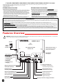
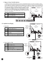
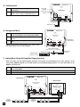
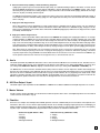
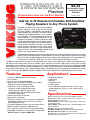
TECHNICAL
Practice
Practice
TELECOM SOLUTIONS
FOR THE
SA-25
Self Amplified Paging
Control Unit with
IR Remote
2 1 S T C E N T U RY
January 3, 2013
Add Up to 25 Remote Controllable Self-Amplified
Paging Speakers to Any Phone System
The SA-25 can directly drive up to 25 self amplified
speakers. Speakers can be Viking’s 2 wire self amplified ceiling speaker model SA-1S, the SA-1H self
amplified paging horn, the older 4 wire legacy Valcom
and Bogen self amplified speakers, or any combination of the above. Viking self amplified speakers have
these advantages: 1) Audio and power are on the
same pair (less copper). 2) Power is 40VDC for lower
current and smaller gauge wire (less copper). 3) NonPolarity sensitive for easier wiring. 4) Each speaker is
infrared remote controllable so there is no need to
manage and wire “background music zones”, install
volume controls on the walls, or climb up ladders to
adjust the volume. The provided SA-IR Infrared Remote controls volume, mute, and enable/disable background music at each speaker as required.
The SA-25 provides paging, loud ringing, and background music when connected to electronic or 1A2 Key
systems, PABX’s, No-KSU phones, multi-line phones, as well as IP phone systems (that have an analog
FXS or FXO port). The SA-25 paging control unit can interface with a paging port or a ringing analog FXS,
CO/Centrex line, PABX/KSU station port or an FXO, unused telephone line input (trunk port).
The SA-25 will generate loud ringing from a ringing analog line or from a dry contact closure. Either a loud electronic warble sound or one of three other soft chime sounds may be selected. An external “night transfer” switch (such as Viking
model NS-1) can be added to turn loud ringing on or off in night bell applications. If a music source is connected to the SA25, background music can be enabled or disabled at any Viking self amplified speaker using the provided SA-IR infrared
remote control. Background music is inhibited during paging. The SA-25 is easy to install and comes complete with a power
supply. The Viking model SA-X12 Expander / Adapter can be used if additional self amplified speakers are required.
Features
Applications
•
•
•
•
•
•
•
•
•
•
•
•
•
•
•
•
•
•
Includes (1) SA-IR Infrared Remote Control
Easy to install
Drive up to 25 self amplified speakers
Separate volume controls for Auxiliary Input, Paging,
Ringing Tones and Background Music
Choose from up to 4 loud ringing sounds:
- Electronic warble (traditional loud ringer)
- Double gong (two identical “gong” tones)
- Quadruple chime (four descending chime tones)
- Door chime (ding-dong)
Provides loud ringing or night bell
Night transfer switch input
Page from a ringing C.O. line, Centrex line, paging port,
unused phone system trunk input (FXO), or ringing
analog station port (FXS)
Can provide background music from an external source
600 Ohm output to cascade to additional units
Use multiple units to drive more self amplified speakers
Expandable 12 speakers at a time with the Viking model
SA-X12 Expander / Adapter (DOD# 529)
Amplified loud paging
Loud ringing
Night bell
Background music
Sound masking
For unused phone system trunk input (FXO), ringing
analog station port (FXS), C.O. line, Centrex line, or
paging port
Specifications
Power: 120V AC/15V AC 2.2A UL listed adapter provided
Dimensions: 210mm x 159mm x 45mm (8.25" x 6.25" x 1.75")
Shipping Weight: 1.5kg (3.2 lbs.)
Environmental: 0°C to 32°C (32°F to 90°F) with 5% to 95% noncondensing humidity
Paging Output: Viking 40V two wire, and Valcom/Bogen 24V
four wire protocols.
Speakers: Up to 25 self amplified speakers
Talk Battery Output: 40V DC (loop current 30mA nominal)
Maximum Wire Run Length: See chart on page 3
Connections: (1) 3.5mm (1/8”) audio jack, (1) 2.1mm barrel jack
(20) cage clamp screw terminals
IF YOU HAVE A PROBLEM WITH A VIKING PRODUCT, PLEASE CONTACT: VIKING TECHNICAL SUPPORT AT (715) 386-8666
Our Technical Support Department is available for assistance Monday 8am - 4pm and Tuesday through Friday 8am - 5pm central time. So that we can give you better service, before you call please:
1. Know the model number, the serial number and what software version you have (see serial label).
2. Have your Technical Practice in front of you.
3. It is best if you are on site.
RETURNING PRODUCT FOR REPAIR
RETURNING PRODUCT FOR EXCHANGE
The following procedure is for equipment that needs repair:
1. Customer must contact Viking's Technical Support Department at 715-386-8666 to obtain a Return Authorization (RA)
number. The customer MUST have a complete description of the problem, with all pertinent information regarding the
defect, such as options set, conditions, symptoms, methods to duplicate problem, frequency of failure, etc.
2. Packing: Return equipment in original box or in proper packing so that damage will not occur while in transit. Static
sensitive equipment such as a circuit board should be in an anti-static bag, sandwiched between foam and individually boxed. All equipment should be wrapped to avoid packing material lodging in or sticking to the equipment. Include
ALL parts of the equipment. C.O.D. or freight collect shipments cannot be accepted. Ship cartons prepaid to:
Viking Electronics, 1531 Industrial Street, Hudson, WI 54016
3. Return shipping address: Be sure to include your return shipping address inside the box. We cannot ship to a PO Box.
4. RA number on carton: In large printing, write the R.A. number on the outside of each carton being returned.
The following procedure is for equipment that has failed out-of-box (within 10 days of purchase):
1. Customer must contact Viking’s Technical Support at 715-386-8666 to determine possible causes for the problem. The
customer MUST be able to step through recommended tests for diagnosis.
2. If the Technical Support Product Specialist determines that the equipment is defective based on the customer's input
and troubleshooting, a Return Authorization (R.A.) number will be issued. This number is valid for fourteen (14)
calendar days from the date of issue.
3. After obtaining the R.A. number, return the approved equipment to your distributor, referencing the R.A. number. Your
distributor will then replace the product over the counter at no charge. The distributor will then return the product to
Viking using the same R.A. number.
4. The distributor will NOT exchange this product without first obtaining the R.A. number from you. If you haven't
followed the steps listed in 1, 2 and 3, be aware that you will have to pay a restocking charge.
LIMITED WARRANTY
Viking warrants its products to be free from defects in the workmanship or materials, under normal use and service, for a period of one year from the date of purchase from any authorized Viking distributor or 18 months from the date manufactured, which ever is greater. If at any time during the warranty period, the product is deemed defective or malfunctions, return the product to Viking Electronics, Inc., 1531 Industrial Street, Hudson, WI., 54016. Customer must contact Viking's
Technical Support Department at 715-386-8666 to obtain a Return Authorization (R.A.) number.
This warranty does not cover any damage to the product due to lightning, over voltage, under voltage, accident, misuse, abuse, negligence or any damage caused by use of the product by the purchaser or others.
NO OTHER WARRANTIES. VIKING MAKES NO WARRANTIES RELATING TO ITS PRODUCTS OTHER THAN AS DESCRIBED ABOVE AND DISCLAIMS ANY EXPRESS OR IMPLIED WARRANTIES OR MERCHANTABILITY OR FITNESS FOR ANY PARTICULAR PURPOSE.
EXCLUSION OF CONSEQUENTIAL DAMAGES. VIKING SHALL NOT, UNDER ANY CIRCUMSTANCES, BE LIABLE TO PURCHASER, OR ANY OTHER PARTY, FOR CONSEQUENTIAL, INCIDENTAL, SPECIAL OR EXEMPLARY DAMAGES ARISING OUT OF OR RELATED TO THE SALE OR USE OF THE PRODUCT SOLD HEREUNDER.
EXCLUSIVE REMEDY AND LIMITATION OF LIABILITY. WHETHER IN AN ACTION BASED ON CONTRACT, TORT (INCLUDING NEGLIGENCE OR STRICT LIABILITY) OR ANY OTHER LEGAL THEORY, ANY LIABILITY OF VIKING SHALL
BE LIMITED TO REPAIR OR REPLACEMENT OF THE PRODUCT, OR AT VIKING'S OPTION, REFUND OF THE PURCHASE PRICE AS THE EXCLUSIVE REMEDY AND ANY LIABILITY OF VIKING SHALL BE SO LIMITED.
IT IS EXPRESSLY UNDERSTOOD AND AGREED THAT EACH AND EVERY PROVISION OF THIS AGREEMENT WHICH PROVIDES FOR DISCLAIMER OF WARRANTIES, EXCLUSION OF CONSEQUENTIAL DAMAGES, AND EXCLUSIVE REMEDY AND LIMITATION OF LIABILITY, ARE SEVERABLE FROM ANY OTHER PROVISION AND EACH PROVISION IS A SEPARABLE AND INDEPENDENT ELEMENT OF RISK ALLOCATION AND IS INTENDED TO BE ENFORCED
AS SUCH.
Features Overview
!
IMPORTANT: Electronic devices are susceptible to lightning and power station electrical surges from both the AC outlet and the telephone line. It is recommended that a surge protector be installed to protect against such surges.
120V AC
VIKING ©
MODEL SA-25
VIKING
ELECTRONICS
HUDSON, WI 54016
15V AC
Adapter
Included
SELF AMPLIFIED PAGING
CONTROL UNIT
POWER
15 VAC
MASTER
VOLUME
OUTPUT TO
SELF AMPLIFIED
PAGING SPEAKERS
FOUR
WIRE
TWO
WIRE
LED Indicators
1. Power ON
2. Fault Protection (Blue)
3. Auxiliary Audio
4. Page Audio
5. Ring Trip
6. Contact Closure
7. Ringing
2
3
4
5
AUX
IN
6
7
8
9
PAGE PAGE
IN CONTACT
10 11 12 13 14 15
NIGHT
TRANSFER
RINGING
LINE
16 17 18 19 20
BACKGROUND
MUSIC IN
Output to Viking 40V 2-wire
self-amplified speakers
Background Music In:
Connect to a music source
to provide background music.
600 Ohm audio for
cascading additional units
Night Transfer Input: To
enable/disable loud ringing.
Output to Valcom/Bogen 24V
4-wire self-amplified speakers
Contact Closure Input: To
trigger loud ringing.
Aux In (audio input)
Ringing Line Input: To
trigger loud ringing.
Paging Input
Page Contact Input
2
1
DIP Switches
(see page 7)
CONTACT
CLOSURE
600 OHM
AUDIO
OUT IN
Master Volume Control: To
limit the maximum volume
setting of the speakers.
Ring Trip / Trunk Port / Paging Port Switch
Installation and Programming
A. Wiring Self-Amplified Speakers
1. Viking SA Series Two-Wire Speakers
VIKING
Step 1. Determine the wire run length and number of
SA-1S self-amplified ceiling speakers, and/or
SA-1H self-amplified paging horns for each run.
MODEL SA-25
©
VIKING
ELECTRONICS
HUDSON, WI 54016
SELF AMPLIFIED PAGING
CONTROL UNIT
POWER
15 VAC
Step 2. Use the chart below to determine the minimum
recommended wire gauge to use.
MASTER
VOLUME
OUTPUT TO
SELF AMPLIFIED
PAGING SPEAKERS
Step 3. Wire each run to pins 1 and 2.
TWO
WIRE
FOUR
WIRE
CONTACT
CLOSURE
600 OHM
AUDIO
Step 4. Adjust the volume of each speaker with the Viking
SA-IR Infrared Remote Control.
AUX
IN
OUT IN
1
2
3
4
5
6
7
8
Master
Volume
Control
9
PAGE PAGE
IN CONTACT
NIGHT
TRANSFER
RINGING
LINE
16 17 18 19 20
10 11 12 13 14 15
BACKGROUND
MUSIC IN
600 ft
VIKING ®
VIKING ®
VIKING ®
Step 5. Use the Master Volume control to limit the
maximum speaker volume when the infrared
remote has them turned up all the way.
250 ft
Example: Eight (8) SA-1S speakers on a 600 ft long wire run.
Use at minimum #18 AWG copper wire pair as
recommended in the chart below.
Example: Three (3) SA-1H horns on a 250 ft
long wire run. Use at minimum #24 AWG copper
wire pair as recommended in the chart below.
25
#24
#18
#16
#16
20
#24
#20
#18
#18
#16
16
#24
#22
#20
#20
#16
#16
12
#24
#24
#24
#22
#18
#18
#16
10
#24
#24
#24
#24
#20
#18
#18
#16
8
#24
#24
#24
#24
#22
#20
#18
#16
#16
6
#24
#24
#24
#24
#24
#24
#22
#20
#18
#16
5
#24
#24
#24
#24
#24
#24
#24
#20
#20
#18
#16
4
#24
#24
#24
#24
#24
#24
#24
#22
#20
#18
#16
#16
3
#24
#24
#24
#24
#24
#24
#24
#24
#24
#22
#20
#18
#16
2
#24
#24
#24
#24
#24
#24
#24
#24
#24
#24
#22
#20
#18
1
#24
#24
#24
#24
#24
#24
#24
#24
#24
#24
#24
#24
#24
100
200
250
300
400
500
600
800
1000
1200
1600
2000
2500
Number of Speakers on the Two-Wire Run
Recommended Minimum AWG (American Wire Gauge) Size
for Viking SA-1S Self-Amplified Speakers on a Two-Wire Run
Total Distance of Two-Wire Run in Feet
3
2. Bogen or Valcom Four-Wire Speakers
The SA-25 is backwards compatible with legacy four-wire self-amplified loud speakers such as those from Bogen or Valcom.
Use wire gauge size chart on previous page, but go two sizes larger since 24V power has more current loss then Vikings 40V
two wire protocol. For example, the chart says to use #16 gauge wire for 8 speakers on a 1000 foot run; but instead use #14
gauge wire when using Valcom and Bogen legacy speakers. The SA-25 can power up to 25 Bogen or Valcom speakers (equal
to 25 “Valcom Power Units”), if no Viking SA series two wire speakers are used.
If a combination of Viking SA series two wire speakers and Bogen or Valcom
VIKING © MODEL SA-25
speakers are used, the SA-25 can power up to a combined total of 25 speakers.
Larger systems can be achieved by adding Viking model SA-X12 for more Viking
SA series two wire speakers, and/or adding a Bogen or Valcom 24V power supSELF AMPLIFIED PAGING
ply for more 4 wire speakers.
CONTROL UNIT
VIKING
ELECTRONICS
HUDSON, WI 54016
POWER
15 VAC
Step 1. Wire the Red & Green (tip and ring) pair of wires
to screw terminals 6 & 7.
MASTER
VOLUME
OUTPUT TO
SELF AMPLIFIED
PAGING SPEAKERS
TWO
WIRE
FOUR
WIRE
CONTACT
CLOSURE
600 OHM
AUDIO
AUX
IN
OUT IN
Step 2. Wire the Yellow & Black (24V power) pair of wires
to screw terminals 8 & 9.
1
2
3
4
5
6
7
8
9
RINGING
LINE
PAGE PAGE
IN CONTACT
NIGHT
TRANSFER
BACKGROUND
MUSIC IN
16 17 18 19 20
10 11 12 13 14 15
Step 3. Adjust volume manually at each speaker.
Example: Bogen or Valcom speakers.
Red & Green
(Tip and Ring)
Yellow & Black
(24V power)
VIKING ©
B. Amplified Loud Paging
1. Paging Port
Step 1. Move the TALK BATTERY DIP switch to the
OFF position (DIP switch 1).
MODEL SA-25
VIKING
ELECTRONICS
HUDSON, WI 54016
Page LED
Indicator
SELF AMPLIFIED PAGING
CONTROL UNIT
POWER
15 VAC
Page Level
Trim Pot
MASTER
VOLUME
OUTPUT TO
SELF AMPLIFIED
PAGING SPEAKERS
FOUR
WIRE
TWO
WIRE
Step 2. Move slide switch to PAGING PORT.
CONTACT
CLOSURE
600 OHM
AUDIO
OUT IN
Step 3. Connect pins 12 and 13 to the paging port output.
1
2
3
4
AUX
IN
5
6
7
8
9
PAGE PAGE
IN CONTACT
RINGING
LINE
NIGHT
TRANSFER
16 17 18 19 20
10 11 12 13 14 15
BACKGROUND
MUSIC IN
Step 4. Connect pins 14 and 15 to the paging contacts
(if available).
Step 5. Adjust the page level trim pot so the Page LED
flashes with page audio (see Operation page 8).
ON
OFF
Paging
Port
1
Page Contact
Closure (if available)
Paging Port
VIKING ©
2. Trunk / Line Port / FXO
Step 1. Move the TALK BATTERY DIP switch to the ON
position (DIP switch 1).
Step 2. Move slide switch to TRUNK PORT.
Page LED
Indicator
SELF AMPLIFIED PAGING
CONTROL UNIT
POWER
15 VAC
Page Level
Trim Pot
MASTER
VOLUME
OUTPUT TO
SELF AMPLIFIED
PAGING SPEAKERS
Step 3. Connect pins 12 and 13 to an unused telephone
line input (trunk port).
Step 4.
MODEL SA-25
VIKING
ELECTRONICS
HUDSON, WI 54016
FOUR
WIRE
TWO
WIRE
CONTACT
CLOSURE
600 OHM
AUDIO
OUT IN
Adjust the page level trim pot so the page LED
flashes with page audio (see Operation page 8).
1
ON
2
3
4
5
AUX
IN
6
7
8
9
PAGE PAGE
IN CONTACT
10 11 12 13 14 15
RINGING
LINE
16 17 18 19 20
BACKGROUND
MUSIC IN
ON
Trunk
Port
1
4
NIGHT
TRANSFER
Unused Telephone
Line Input (Trunk Port)
FXO
- OR -
Analog
Phone
VIKING ©
3. Ring Trip / FXS
VIKING
ELECTRONICS
HUDSON, WI 54016
Page LED
Indicator
Step 1. Move the TALK BATTERY DIP switch to the
OFF position (DIP switch 1).
MODEL SA-25
SELF AMPLIFIED PAGING
CONTROL UNIT
POWER
15 VAC
Page Level
Trim Pot
MASTER
VOLUME
OUTPUT TO
SELF AMPLIFIED
PAGING SPEAKERS
Step 2. Move slide switch to RING TRIP.
FOUR
WIRE
TWO
WIRE
CONTACT
CLOSURE
600 OHM
AUDIO
OUT IN
Step 3. Connect pins 12 and 13 to a ringing analog
station port (FXS).
1
2
3
4
5
AUX
IN
6
7
8
9
PAGE PAGE
IN CONTACT
10 11 12 13 14 15
RINGING
LINE
NIGHT
TRANSFER
16 17 18 19 20
BACKGROUND
MUSIC IN
Step 4. Adjust the page level trim pot so the Page LED
flashes with page audio (see Operation page 8).
ON
OFF
Ring
Trip
1
Ringing Analog
Station Port (FXS),
CO Line or Centrex Line
VIKING ©
C. Loud Ringing/Night Bell
1. Ringing Analog Lines
Step 1. Connect pins 16 and 17 to a ringing line or
PABX station.
Loud Ringing
LED Indicator
SELF AMPLIFIED PAGING
CONTROL UNIT
POWER
15 VAC
MASTER
VOLUME
OUTPUT TO
SELF AMPLIFIED
PAGING SPEAKERS
Step 2. The loud ringing pot may be adjusted to set
volume.
Step 3.
MODEL SA-25
VIKING
ELECTRONICS
HUDSON, WI 54016
FOUR
WIRE
TWO
WIRE
CONTACT
CLOSURE
600 OHM
AUDIO
OUT IN
A night transfer switch may be added to pins
19 and 20 to enable and disable loud ringing.
1
2
3
4
5
AUX
IN
6
7
8
Loud Ringing
Trim Pot
9
PAGE PAGE
IN CONTACT
RINGING
LINE
NIGHT
TRANSFER
16 17 18 19 20
10 11 12 13 14 15
BACKGROUND
MUSIC IN
Optional Night Transfer Switch
Disables loud ringing when closed
(not included). See Viking model
NS-1 (DOD# 540).
Ringing Line or
PABX Station
2. Dry Contact (Common Audible) Closure (contacts not included)
Step 1. Connect the dry contact closure
to pins 18 and 19.
Step 2. A dry contact closure will initiate
loud ringing.
VIKING ©
MODEL SA-25
VIKING
ELECTRONICS
HUDSON, WI 54016
SELF AMPLIFIED PAGING
CONTROL UNIT
POWER
15 VAC
MASTER
VOLUME
OUTPUT TO
SELF AMPLIFIED
PAGING SPEAKERS
FOUR
WIRE
TWO
WIRE
CONTACT
CLOSURE
600 OHM
AUDIO
OUT IN
1
2
3
4
5
AUX
IN
6
7
8
9
PAGE PAGE
IN CONTACT
10 11 12 13 14 15
Dry Contact Closure
(not included)
RINGING
LINE
16 17 18 19 20
NIGHT
TRANSFER
BACKGROUND
MUSIC IN
Optional Night Transfer Switch - Disables
loud ringing when closed (not included). See
Viking model NS-1 (DOD# 540).
5
VIKING ©
D. Auxiliary Input
MODEL SA-25
VIKING
ELECTRONICS
HUDSON, WI 54016
Aux In LED
Indicator
Step 1. Connect pins 10 and 11 to any other line level
audio source.
Step 2. Adjust the Aux In level trim pot so the Aux In LED
flashes with aux audio (see Operation page 8).
SELF AMPLIFIED PAGING
CONTROL UNIT
POWER
15 VAC
Aux In Level
Trim Pot
MASTER
VOLUME
OUTPUT TO
SELF AMPLIFIED
PAGING SPEAKERS
FOUR
WIRE
TWO
WIRE
CONTACT
CLOSURE
600 OHM
AUDIO
OUT IN
1
2
3
4
5
AUX
IN
6
7
8
9
PAGE PAGE
IN CONTACT
RINGING
LINE
16 17 18 19 20
10 11 12 13 14 15
NIGHT
TRANSFER
BACKGROUND
MUSIC IN
Audio Source
VIKING ©
E. Background Music
MODEL SA-25
VIKING
ELECTRONICS
HUDSON, WI 54016
Step 1. Connect a background music source to the background
music in jack using the 1/8” (3.5mm) cable provided.
SELF AMPLIFIED PAGING
CONTROL UNIT
POWER
15 VAC
Step 2. Adjust the background music trim pot to the desired
volume.
MASTER
VOLUME
OUTPUT TO
SELF AMPLIFIED
PAGING SPEAKERS
FOUR
WIRE
TWO
WIRE
Step 3. Background music will play when all other inputs are
idle.
1
2
3
4
5
AUX
IN
6
7
8
Background
Music Trim Pot
CONTACT
CLOSURE
600 OHM
AUDIO
OUT IN
9
RINGING
LINE
PAGE PAGE
IN CONTACT
NIGHT
TRANSFER
BACKGROUND
MUSIC IN
16 17 18 19 20
10 11 12 13 14 15
* Note: If your music source provides a 1/8” stereo output,
you might need a mono to stereo adapter.
* Mono to Stereo Adapter
(Radio Shack # 274-374, not included)
1/8" Mono Cord
(included)
Background Music
Source (not included)
F. Adding More Viking Self-Amplified Paging Speakers
When more than (25) self-amplified paging speakers are required, a second SA-25 for (25) more speakers, or the
Viking model SA-X12 Expander can be used to add (12) self-amplified paging speakers. For more information on the
SA-X12, see DOD# 529.
Step 1. Connect the SA-25 600 Ohm Output (pins 3 & 4) to the 600 Ohm Audio Input (pins 5 & 6) on the SA-X12 or pins
4 & 5 on the SA-25.
Step 2. Connect up to (12) self-amplified speakers to a SA-X12 Expander, or (25) to a SA-25.
Step 3. Adjust the volume control of the SA-X12 if needed.
Model SA-25
VIKING
©
MODEL SA-25
VIKING
ELECTRONICS
HUDSON, WI 54016
Model SA-X12
SELF AMPLIFIED PAGING
CONTROL UNIT
POWER
15 VAC
MASTER
VOLUME
5
6
7
8
9
10 11 12 13 14 15
16 17 18 19 20
BACKGROUND
MUSIC IN
SELF AMPLIFIED PAGING
EXPANDER / ADAPTER
OUTPUT TO
SELF AMPLIFIED
PAGING SPEAKERS
1
POWER
LED
Up to 25
self-amplified
speakers.
6
Up to 12
self-amplified
speakers.
2
COMMON
4
NIGHT
TRANSFER
600 OHM
3
RINGING
LINE
4 / 8 / 16 OHM
OUT IN
2
PAGE PAGE
IN CONTACT
25V / 70V
CONTACT
CLOSURE
AUX
IN
POWER 13.8 VAC
FOUR
WIRE
600 OHM
AUDIO
1
MODEL SA-X12
VIKING
ELECTRONICS
HUDSON, WI 54016
OUTPUT TO
SELF AMPLIFIED
PAGING SPEAKERS
TWO
WIRE
VIKING ©
3
4
5
6
GAIN
G. DIP Switch Programming
VIKING ©
MODEL SA-25
VIKING
ELECTRONICS
HUDSON, WI 54016
ON
ON
ON
OFF
1
2
3
MASTER
VOLUME
OUTPUT TO
SELF AMPLIFIED
PAGING SPEAKERS
4
FOUR
WIRE
TWO
WIRE
2
3
4
5
AUX
IN
6
7
8
9
PAGE PAGE
IN CONTACT
10 11 12 13 14 15
RINGING
LINE
5
16 17 18 19 20
Position
OFF
ON
OFF
ON
OFF
ON
OFF
ON
Switch 5
OFF
OFF
ON
ON
Switch 6
OFF
ON
OFF
ON
6
7
NIGHT
TRANSFER
BACKGROUND
MUSIC IN
Dip Switches shown in
factory default settings.
Switch
1
1
2
2
3
3
4
4
OFF
CONTACT
CLOSURE
600 OHM
AUDIO
OUT IN
1
ON
SELF AMPLIFIED PAGING
CONTROL UNIT
POWER
15 VAC
Dip Switches shown in
factory default settings.
Description
Talk battery disabled (use for Paging Port and Ring Trip)
Talk battery enabled (use for Trunk Port)
Normal priority: Aux In → Page → Ringing → Background music
Alternative priority: Page → Aux In → Ringing → Background music
Pre page alert tone disabled
Pre page alert tone enabled
Post page alert tone disabled
Post page alert tone enabled
Loud Ringing Sound Output
Electronic warble
Double gong
Quadruple chime
Door chime
Switch 7
OFF
ON
Description
Normal mode (see Operation section H)
Smart mode (see Operation section H)
Sound Output Specifications
All tones require a minimum of 180ms of ringing voltage (or contact closure) to trigger. Once triggered, the electronic warble will run continuously until ringing stops (or contacts open). All other tones (double gong, quadruple chime, doorbell) will
run through their full sequence once and will not cycle again until the ringing stops (or contact opens) for at least 50ms and
a second ring signal (or contact closure) triggers them again.
A. Electronic Warble (Traditional Loud Ringer)
Duration of Contact Closure
On
Frequency alternates between 1440 Hz and 1140 Hz 20 times per second.
Off
B. Double Gong (Two “Gong” Tones)
On
Off
0.74
sec
575 Hz
2.2 sec
575 Hz
7
C. Quadruple Chime (Four Descending Chime Tones)
0.36
sec
0.36
sec
0.36
sec
888 Hz
699 Hz
584 Hz
On
2.2 sec
492 Hz
Off
D. Door Chime (Ding-Dong)
2.7
sec
0.36
sec
On
Off
794 Hz
526 Hz
Operation
A. Background Music In
This audio input allows background music from an external source to plug into the SA-25. While any other input is active, background music is turned off, so music will only be heard through the speakers when all other inputs are idle. A 3.5mm (1/8”) audio
cable is provided, and the music level can be set using the trim POT just behind the Background Music input jack.
B. Loud Ringing
1. Line In
This input provides loud ringing through the speakers whenever ringing voltage is detected. Connect an analog ringing line to
screw terminals 16 & 17 for this feature.
2. Contact Closure
This input provides loud ringing through the speakers whenever a contact closure is detected. Some phone systems provide a
“common audible” dry contact closure whenever a call is coming in. Wire the contact closure across screw terminals 18 & 19 to
provide loud ringing from the SA-25.
3. Night Transfer
This input can be used to disable loud ringing. For example, if loud ringing is only necessary during off business hours, an external switch can be added to disable loud ringing during the day, and transfer it back on at night. Wire an external switch (such
as Viking model NS-1) across screw terminals 19 & 20. When the switch is closed, loud ringing will be disabled.
4. Loud Ringing Sounds
The SA-25 can produce one of 4 selectable loud ringing sounds. Use DIP Switches 5 and 6 to choose between Electronic
Warble, Double Gong, Quadruple Chime, or Door Chime sounds for loud ringing. Select the Electronic Warble tone (traditional
loud ringing) for noisy areas. The softer chime tones work well in less noisy environments.
C. Paging In
This audio input allows paging from a ringing analog station port (FXS), CO line or Centrex line, a phone system’s unused trunk/line
input (FXO) or dedicated telephone, or a paging port. Wire the appropriate page source to screw terminals 12 & 13 as shown in the
Installation section, and follow the operation for your type of paging as described below.
1. Ringing Analog Station (FXS), C.O. Line, or Centrex Line
If paging from a ringing analog station (FXS), C.O. line, or Centrex line, DIP Switch 1 must be OFF, and the Slide Switch set to
RING TRIP. Dial the station or phone line number, and the SA-25 will answer the line after the first ring is detected. Wait for the
Pre-Page Alert Tone to pass (if enabled), and then speak. The SA-25 will drop the line once it detects silence, busy signal,
reorder signal, or a CPC break. If none of those are detected, the SA-25 will drop the line at a default time out of 60 seconds.
8
2. Unused Trunk/Line Input (FXO), or Dedicated Analog Telephone
If paging from a phone system’s unused trunk/line input (FXO), or a dedicated analog telephone, DIP Switch 1 must be turned
ON (so the SA-25 will provide the necessary 40V DC Talk Battery), and the Slide Switch set to TRUNK. To page, either access
that trunk port or go off hook on the analog telephone. Loop current will be detected and activate paging. Wait for the Pre-Page
Alert Tone to pass (if enabled), and then speak.
The SA-25 will automatically provide a CPC signal to the phone system if the trunk port has not dropped within 60 seconds. If
a user fails to release the trunk after making a page, the CPC signal acts as a safety net to clear the trunk so it will be available
for the next page.
3. Paging Port with Page Contacts
When using a phone system’s paging port, if a page contact closure is available from the phone system, wire the contacts to
screw terminals 14 & 15. DIP Switch 1 must be turned OFF and the Slide Switch set to PAGING. To page, simply access the
phone system’s paging port, (the contact closure will activate the SA-25’s paging input). Wait for the Pre-Page Alert Tone to pass
(if enabled), and then speak.
4. Paging Port without Page Contacts
DIP Switch 1 must be turned OFF and the Slide Switch set to PAGING. When paging from a paging port and there are no page
contacts available, the SA-25 relies on its internal Voice Activation Switch (VOX) feature to switch to paging when voice audio
is detected. This means the voice audio must be loud enough to be detected. The VOX sensitivity can be adjusted using the
Page Level Trim Pot located just behind the Page In screw terminals. Adjust this Pot so the Page LED flashes with page audio.
A pre-page alert tone would not happen until the person starts talking, so it is recommended that the Pre-Page Alert Tone is disabled (set DIP Switch 3 to OFF), unless using the below Tip. To page, simply access the phone system’s paging port and speak.
Tip: When relying on VOX activation, the very beginning of the page will be cut off. If this is objectionable, the user can make
some sort of sound (like pressing a touch tone, or saying the word “paging”) to activate the VOX before speaking. This will be
especially helpful when using the SA-25 in the Smart Mode where an extra fraction of a second is needed for the SA-25 to signal the speakers that have been muted for no background music, to turn themselves back on.
D. Aux In
This audio input allows any additional audio sources to be connected into the SA-25 on screw terminals 10 & 11. Possible uses are:
audio from another paging system, clock controlled tones to announce work shift times (see Viking model CTG-1), emergency siren
(see Viking model DNA-510 or MTG-10), digitally recorded announcements (see Viking model DVA-500A or DVA-2WA), etc.
The SA-25 relies on its internal Voice Activation Switch (VOX) feature to switch to the Aux Input when audio is loud enough to be
detected. The VOX sensitivity can be adjusted using the Aux In Level Trim Pot located just behind the Aux In screw terminals. Adjust
this Pot so the Aux In LED flashes with Aux audio. When relying on VOX activation, the very beginning of the audio will be cut off.
This will be especially noticeable when using the SA-25 in the Smart Mode, where an extra fraction of a second is needed for the
SA-25 to signal the speakers that have been muted for no background music to turn themselves back on.
E. 600 Ohm Output / Input
This audio output / input is provided so that a SA-X12 or a SA-25 can be added if additional self-amplified speakers are needed.
F. Master Volume
A master volume control is provided. Use this to limit the maximum speaker volume of the self-amplified speakers when the infrared
remote has them turned all the way up.
G. Priorities
Since there are multiple uses and inputs to the SA-25, priorities need to be established to prevent contentions. If two inputs are activated at the same time, the one with the highest priority will take effect. Examples: Paging is higher priority then Loud Ringing, so
Paging would interrupt loud ringing tones. The Background Music input is always the lowest priority, and thus can be interrupted by
any other input. Two different DIP Switch programmable Priority selections are available as listed below.
Normal Priority (DIP Switch 2 OFF)
Alternative Priority (DIP Switch 2 ON)
1.
2.
3.
4.
1. Paging
2. Aux In
3. Ringing
4. Background Music
Aux In
Paging
Ringing
Background Music
9
H. Infrared Remote Control
Infrared remote control is one of several features that set Viking’s self amplified paging system ahead of older legacy Valcom and
Bogen systems. These older 4 wire self amplified systems required twice the copper to each speaker then Viking’s 2 wire system.
The older 4 wire systems also required the installer to manage background music zones, and hardwire each speaker to one zone
or the other, and then have to walk around with a ladder to manually set the volume of each speaker to hopefully the proper level.
If the user decides one of the speakers should now have background music or a volume adjustment, it’s back up the ladder to pull
more wire, and adjust more pots.
With the Viking SA Series 2 wire self amplified paging system, the installer can connect all the speakers to the same pair of wires,
and then simply show the user how to point the SA-IR Infrared Remote control at each speaker to adjust volume, mute, and enable
or disable background music.
The Viking model SA-1S and SA-1H self amplified speakers can be controlled with the Viking model SA-IR Infrared Remote control in one of two different ways depending on a DIP Switch setting on the SA-25 as described below.
1. SA-IR Remote Control functionality with SA-25 in “Normal” mode (DIP Switch 7 = OFF):
The SA-IR Remote Control functions essentially like a TV remote control. Each individual speaker volume can be stepped up
or down, or the speaker can be totally muted. When the speaker is muted, pressing the mute button again, or the volume up or
down buttons, will release the mute. A short “beep” will be heard through the speaker when the mute is activated. A long “beep”
will be heard through the speaker when the “MUTE” button is pressed again releasing the mute. The “Normal” mode is recommended when no background music is used.
2. SA-IR Remote Control functionality with SA-25 in the “Smart” mode (DIP Switch 7 = ON):
The “Smart” mode is recommended for installations that use background music. In this special mode the SA-IR Remote Control
“MUTE” button functions as a “mute background music button”. Press the “MUTE” button while background music is playing and
no background music will be heard through that speaker; yet all paging and loud ringing sound will still be amplified through the
speaker. This feature is useful for speakers which are mounted in a meeting room in which pages need to be heard, but background music would be obstructive, or offices in which enabling and disabling background music on a speaker by speaker basis
is needed. This feature enables an office with background music to become a quite meeting room with the push of a button.
In this “Smart” mode, if the SA-IR Remote Control “MUTE” button is pressed during paging or loud ringing, it will immediately
totally mute that speaker. No other pages, loud ringing, or background music will be heard from that speaker until it is un-muted
using the remote control’s “MUTE” or “VOLUME” buttons. Another way to quiet a speaker is to step the volume all the way down
to minimum while background music is playing.
A short “beep” will be heard through the speaker when the mute is activated. A long “beep” will be heard through the speaker
when the “MUTE” button is pressed again releasing the mute. When the mute is released, all paging and loud ringing sounds
as well as background music will be heard through that speaker.
Compatible Products
SA-1S
Self-Amplified Ceiling Speaker
For more info, see DOD# 525
SA-1H
Self-Amplified Paging Horn
with Infrared Receiver
For more info, see DOD# 526
Product Support Line...715.386.8666
SA-IR
Infrared Remote Control
For more info, see DOD# 527
SA-X12
Expander / Adapter
For more info, see DOD# 529
Fax Back Line...715.386.4345
Due to the dynamic nature of the product design, the information contained in this document is subject to change without notice. Viking Electronics, and its affiliates and/or subsidiaries assume no responsibility for errors and omissions contained in this information. Revisions of this document or new editions of it may be issued to incorporate such changes.
10
DOD# 520
Printed in the U.S.A.
ZF303000 Rev A