1
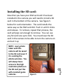
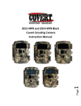
2013 Special Ops‐Code Black Scouting Camera Instruction Manual. Page Watch the set up video on our website at www.dlccovert.com. It’s on our home page! 1 TableofContents Camera button control diagram: ................................................ 4 Installing the batteries: ............................................................... 5 Purchasing your SIM card: .......................................................... 6 Installing your SIM card: ............................................................. 7 Installing the SD card: ................................................................. 8 Setting up the wireless network: ................................................ 9 Formatting the SD card: ............................................................ 10 Send a test photo: .................................................................... 20 Understanding main screen info: ............................................. 21 Page Setting the camera mode: ........................................................ 23 Camera mode settings: ............................................................. 23 Video mode settings: (Fig 20) .................................................. 24 PIR tab: ..................................................................................... 25 GSM tab: ................................................................................... 30 Controlling your camera using SMS: ......................................... 31 SYS tab: ..................................................................................... 35 Viewing photos on the color display: ....................................... 39 Troubleshooting: ...................................................................... 41 Tricks and tips on field setup: ................................................... 44 Warranty: ................................................................................. 46 Warranty Policy and Procedure: ............................................... 46 2 Customizing the camera settings: ............................................. 21 Congratulations on your purchase of the 2013 Special Ops.‐Code Black Scouting camera! We truly value your business and will strive to provide you top quality customer service should you ever need help with any of our products. Check out our other products on our website at www. Dlccovert.com. Page We know the first big question you are going to have once you purchase your Special Ops‐Code Black is how do I get it set up to work over the cellular network. This is very easy if you follow the steps laid out for you in this manual starting on the following pages. We hope you enjoy hassle free performance from this quality product for years to come. 3 The 2013 model of the Spec. Ops‐Code Black is even more exciting than past versions with the addition of SMS texting control from you phone. Now you can control several of the basic functions right from your phone simply by texting it a code. Check out the SMS section for more information. Camerabuttoncontroldiagram: Antenna Color LCD SIM card slot Figure 1 USB SD card slot Page Navigation arrows Selector switch Take photo manually Aux battery jack 4 Delete Menu Select/OK Play Installingthebatteries: Your Special Ops Code Black can function short term on 4AA batteries. Improved battery life on 8‐AA, but we suggest you use 12AA batteries to get the most out of your cameras battery life. Using Covert rechargeable NiMH, 2300mAh, AA batteries can extend the battery life significantly. Install the batteries by sliding the top battery in to the sleeve first, then depressing the spring with the other battery and snapping down in place. Pay attention to the (+) or (‐) molded into each sleeve to determine if you insert the positive or negative end into the sleeve first. Negative battery terminal always contacts the spring. (Fig. 2) Figure 2 5 Page PurchasingyourSIMcard: The Spec. Ops.‐Code Black is designed to send the photos it takes via MMS SIM card technology over the cellular network to any phone or email address instantly once the photo is taken. You will have to purchase a texting package from an AT&T corporate store to get set up to do this. Page You will need to travel to your local AT&T corporate store to purchase a prepaid SIM card that you will then install in the card slot on the side of your camera. Franchise stores might not carry the Go Phone prepaid SIM cards so go to a regular AT&T corporate store. When you talk to an AT&T representative, tell them that you need to purchase a Go Phone Text Feature Package prepaid SIM card that is unlocked. You will also want to be sure that this SIM card is unlocked. 6 You do not have to have a text package for this camera to take photos, but it will not send them instantly to your phone and will only store them on an SD card like traditional scouting cameras. InstallingyourSIMcard: Now that you have your SIM card. Open your camera housing to expose the control panel. Make sure your camera mode selector switch is in the OFF position. On the left side of the camera control panel towards the top is a small card slot. See Figures 3 & 4 below. Figure 3 Figure 4 Page To remove the SIM card, simply press in on the card until it clicks and then release it. 7 Press the card in until it bottoms out and then release. It will snap in place. InstallingtheSDcard: Now that you have your SIM card and it has been installed in the camera you will need to install a SD card in the bottom of the camera. See figure 5 below for card orientation. The card installs the same way as the SIM card did. Push in until it clicks and release. To remove, repeat that process, the card will pop out enough to remove. You can use any SD card size up to 32G. You must have the SD card in the camera to be able to turn the camera on and set it up NOTE: every photo taken with this . camera will be saved to the SD card even if Figure 5 Page photos wireless. You will always have access to the high resolution photos on the SD card just like with standard game cameras. 8 it is sending the Settingupthewirelessnetwork: Page You will need to be patient as the camera does its initial set‐up and looks for cellular service. While finding the network you will see the word searching, Then Searching Network in red on the screen. Once you see a 6 digit number show up at 9 1) Slide selector switch to the right to the SETUP position. Press the MENU button You will see the screen shown below (Fig 6):, Figure 6 2) Press the ► button 2 times to highlight the GSM tab in yellow. Press the ▼ button to highlight the Send Mode option. Press the ► button to toggle the option in the white box to INSTANT. Press OK to save this setting. Your camera can now search for cellular service. the top and the service bar indicator show service bars, you are ready to move on. Press the ►button 3 times to highlight the SYS tab. FormattingtheSDcard: 3) Navigate down by pressing the ▼ button repeatedly until the FORMAT option is highlighted and press OK. You will see the screen shots shown below (Fig 7 & 8). Press the ◄ button to highlight YES and press OK. Your SD card is now formatted. 10 Figure 8 Page Figure 7 4) Next Press the ▲or ▼button repeatedly until only the SYS tab is highlighted in yellow. 5) Press the ◄ arrow (1) time to highlight the GSM tab and navigate down to the DOWNLOAD TOOL and press OK. (Figures 9 & 10) Figure 9 Figure 10 Page 11 6) Turn the camera off by sliding the selector switch to the OFF position 7) Remove the SD card from your camera and insert into your personal PC card reader. 8) Locate the SD card in Windows Explorer and double click on it to show it’s contents. (Fig 11 found on the next page) Figure 11 Double click on the GSMSETUP and then double click on the UOV Setup application. 9) You will see a warning box like Fig. 12 below. Choose YES and the UOV set‐up program will launch. Figure 12 12 Page Figure 13 Page 13 10) You will see the following screen for setting up the GSM options for your camera. This is where you add phone numbers and e‐mail addresses and control the number of wireless photos sent from the camera each day. (Fig 13) 14 Page 11) Send Mode: a. INSTANT: If you want the camera to send you every photo the instant it’s taken, you want to choose this option. b. Max Num: You can control the numbers of photos that are sent to your device or e‐ mail every day. If you want to limit this, put the maximum number of photos you want the camera to send each day in the box. If you want it to send every photo regardless of the number of photos each day, set this value to 0 (zero) c. Daily Report: This option only sends you the last photo taken each day with a report of all the other activity during the day. d. OFF: choose this option if you do not want the camera to send out the photos taken. This will make the camera perform just like a normal trail cam. 15 Page 13) Send Via: a. MMS: Choose the MMS option. b. GPRS: 14) Operator Parameter: a. Country: Choose your Country or Origin in the drop down menu. b. Operator: Choose AT&T in the drop down menu. 15) SMS Switch: Choose the ON option if you want to be able to control the basic functions of your camera by texting it codes from your phone. If you do not want to have wireless control, you can leave the option at OFF. 16) Send to: a. Phone: Choose this option if you only want the photos sent to phone numbers b. Email: Choose this option if you only want the photos sent to chosen e‐mail addresses. c. Both: Choose Both if you want to send to both phone numbers and e‐mail addresses. 16 Page 17) Recipients: a. Phone: Enter up to 4 different phone numbers in the phone number field. You will need to start every number with a 1 followed by the area code and phone number with no spaces or dashes. Place a semicolon (;) between each of the phone numbers with no spaces anywhere. You will need to enter a semicolon after the last entry. b. Email: Enter up to 4 different e‐mail addresses in the Email field. You will need to enter a semicolon AFTER the last entry. The Email option will only be available if you have chosen the Email or Both options. 18) Rename: If you want to change the name given to the camera to something that you can use to identify the camera, set the drop down box to ON. Enter the new camera name in the box. 19) Max Size: This should always be set to 80KB as that is all the wireless networks will allow. 20) Default: If you want to set the camera settings back to the original defaults before changes were made, pick this button. You cannot go back once this button is pressed so make sure you want to re‐set all the settings before you pick this button. 21) Path: The path is the location in which the settings are saved. You will see that the default location is C:\Windows\System32. You will want to change this to point back to your SD card. To do this you will pick the button with the 3 dots on it to the right of the path text bar. This will allow you to choose the SD card from your windows explorer. You must save this information to the SD card for the set up to take place once you put the SD card back into the camera. (Fig 14 – see example on next page) Page 17 Page Figure 14 18 22) Press the OK button to accept the settings and save them to the SD card. You will see the following box pop up (Fig. 15). Pick OK you can then cancel the UOV Setup. Page 23) Remove the SD card from your computer and replace it in the camera. 24) Slide the SELECTOR switch to the SETUP position. Wait for the camera to go through it’s set up process and find cellular service. Normally 15‐20 seconds to see update success 25) Press the MENU button. 26) Press the button that has the CAMERA symbol on it (1) time to manually take a photo with the camera. You will know that a photo has been taken because the photo counter on the screen will say 001. 19 Figure 15 Sendatestphoto: 27) Press the PLAY button to enter the Play mode and then press the MENU button. You will see the following screen. (Fig16) Figure 16 28) Press the ▼to highlight the SEND option and press OK. (Fig 17) Figure 17 Page 29) The LCD screen will start to count up from step 1 to 10. Once you see Send Successful, you have successfully sent your first photo and your camera is ready to take photos. 20 Understandingmainscreeninfo: Camera/Video icon Mega Pixels chosen Cellular carrier # Cellular service indicator Figure 18 # of photos remaining on card 21 # of photos taken Page Battery life indicator Customizingthecamerasettings: Your camera is set to function with the default settings without any further customization. However, you will likely want to at very least set the clock and date. The following information will help you customize your camera settings so you can get the most out of the trail camera experience. To start, Press the MENU button once to open the customization menus. We will start with the CAM system tab. You will see CAM, PIR, GSM, and SYS tabs across the top of the screen. CAM should be highlighted in yellow. (Fig 19) Page 22 Figure 19 Settingthecameramode: Press the ▼ button to highlight the Camera Mode option in yellow. Either Photo or Video will show up in a white box to the right. Press the ►button to toggle between Photo or Video until the option you want shows in the white box. Press OK. NOTE: If you do not press OK, your setting will return back to the previous setting. Cameramodesettings: PHOTO SIZE: Press the ▼or ▲ button to highlight Photo Size in yellow. Page 23 Press the ►arrow repeatedly to toggle between 3mp, 5mp, 8mp, or 12mp. Press OK once the desired option shows in the white box. Keep in mind the higher the MP, the larger the file and the faster your SD card can fill up. PHOTO BURST: Your camera can take a 1, 2 or 3 shot burst every time the PIR is triggered to take a photo. The camera will only send the first photo of the photo burst to your phone or e‐mail. Press the ▲ or ▼ buttons to highlight the PHOTO BURST option: To set this function, press the ►repeatedly to show the 1 Photo, 2 Photo, or 3 Photo option. Press OK to save the desired setting. Videomodesettings:(Fig20) Figure 20 Page Press the ► button to toggle between the VGA and QVGA options. Press OK to save the setting. 24 VIDEO SIZE: You can choose from VGA or QVGA video options. VIDEO LENGTH: You can adjust the length of time the camera takes a video from 5‐60 seconds. Press the ▲ or ▼ button to highlight the VIDEO LENGTH option. Press the ► or ◄ buttons repeatedly to change the number of seconds shown in the white box. Long videos fill the SD card up quickly. PIRtab: Press the ▲ or ▼ buttons repeatedly until only the top tab menu is highlighted in yellow. Press the ► or ◄ button to highlight the PIR tab in yellow. Screen should appear like Fig. 21. Figure 21 Page SENSITIVITY: There may be situations where you might feel the camera is not catching animals that are nearby or maybe the camera is triggering too easily. You can adjust the sensitivity of your camera to help with this. Under most conditions, the 25 NORMAL option will work the best. In high temperatures, the HIGH setting might help differentiate between the outside temps and the body temps of the animal. In cold conditions, you may find that the LOW option is best as the camera can easily differentiate the outside temps from the body temps of the subject. If you are using the time lapse function, you would choose OFF to turn off the PIR. Page TRIGGER INTERVAL: Allows you to customize how often the camera can be allowed to take a photo. Press the ▲ or ▼ arrow to highlight the Trigger Interval option. Repeatedly press the ► or ◄ to adjust the timing. Options are 5‐60 seconds (5 second increments) and 1‐60 minutes. Once you 26 Press the ▼ button to highlight the Sensitivity option. Press the ► button repeatedly to toggle between the options in the white box. Once the desired option is chosen, press the OK button to save the setting. have chosen your desired trigger interval, press the OK button to save the setting. NOTE: We suggest you choose 1minute or greater for the MMS to work properly. Page TIME LAPSE: Press the ▼▲ arrow to highlight the Time‐Lapse option. This option allows your camera to automatically take a photo without being triggered by the PIR. If you already set the Sensitivity to OFF, then the camera will only take photos when the Time‐Lapse option is on. If you have the PIR set to LOW, NORMAL, or HIGH, the camera will also take photos when the PIR is triggered. To turn the Time‐Lapse option on, use the ►◄ buttons to choose a time option. 5‐60 seconds (in 5 second increments) and 2‐60 minutes. Once you have chosen the time option you want, 27 TIP: You can press and hold the ◄ or ► button to speed through the settings rather than repeatedly pressing the button. press OK to save the setting. The camera will continuously take photos in timed increments you set. Remember, this will generate a lot of photos and you may want to limit the number of photos sent via MMS daily. START‐STOP: If you only want your camera to be on during part of the day each day you can set the Start‐Stop function. Press the ▲▼ buttons to highlight the Start‐Stop option. The default setting is OFF. Press the ► button to toggle the setting to ON and press OK. Figure 23 Once you press OK you will see the screen in Fig. 22. Use the ▲▼ buttons to set the time in hours Page Figure 22 28 See Fig 22 & 23 below (military time) and press the ► button to change to minutes and use the ▲▼ to set the minutes. Press the ► button to navigate to the Stop settings and repeat the process from above to set the Stop time. You can press the ►◄ buttons to navigate back through the settings if necessary. Once you have the start‐stop times set, press OK to save the settings. 29 Page GSMtab: Press the ▼▲ buttons until just the PIR tab is highlighted and then use the ► to highlight the GSM option. Most of the settings under the GSM tab are controlled in the original camera set up. You will not be able to make changes to these settings from the camera. You would have to repeat the steps for setting up the wireless network to make changes to these settings. Page Press the ▼ button repeatedly until you highlight the SMS Switch option. Use the ► button to toggle 30 SMS SWITCH The only option that is controlled under the GSM tab is the SMS Switch. This switch controls whether you can send SMS texts to your camera to change the basic settings. If this switch is set to ON, you will be able to communicate with your camera via text message through your phone. If the setting is set to OFF, this function is disabled. between ON and OFF. Press the OK button to save the settings. ControllingyourcamerausingSMS: You can control many of the basic functions of your camera from your cell phone by sending it codes via text message. You can control the following functions on your camera via SMS. Set Camera/Video Mode Acquire pictures Add/delete e‐mail addresses or phone numbers of recipients Show the camera’s altitude and longitude Page The person who has control of this function (commander phone number) is the person who is in position 1 in the GSM set up in the phone number list. This person can delete/add the subordinates of phone numbers 2, 3 and 4. 31 IMPORTANT NOTE: the SMS switch MUST be set to ON in the GSM set‐up for the SMS function to work. Both the “commander phone number” and the subordinates have the rights to edit the SMS command orders to control the camera. See table 1 Table 1 ITEM Add phone number Delete phone number Add email address Delete email address Set Picture mode Set Video mode Acquire Picture Location MMS on SMS Command Order #140#1#phone number# #140#0#phone number# #141#1#email address# #141#0#email address# #310#P# #310#v# #500# #510# #200#On# Page You will text the camera phone number that you were given with the SIM card using the codes listed above for the specific function changes. 32 ACQUIRE PICTURE: If you send #500# to acquire picture, the camera will capture a single picture immediately and send it to the email addresses and/or phone numbers listed in the GSM settings. Page MMS ON/MMS OFF: If you want the camera to stop sending you photos, you can send the code from Table 1 to shut it OFF and back ON. If set to OFF, you will not receive photos or Daily reports to your phone or e‐mail. Your camera will always still record all the events on the SD card. 33 LOCATION: Your camera is equipped with a GPS locator. If your camera is lost or stolen, text #510# and it will send you back it’s longitude and latitude coordinates of the location of the camera which you can then provide to the authorities for recovery. You want to be sure you use your password protection option and keep your SMS switch set to ON. If the SMS switch is set to OFF, this function will not work. IMPORTANT NOTE: Remember you need a 1 before each phone number and you can not use any spaces, dashes or hyphens. 34 Page SYStab: The SYS tab controls all the internal system information such as Setting the clock, Time stamp, Flash range, Password, Over Write, and Format. (Fig 24) Figure 24 Page Figure 25 35 SETTING THE CLOCK: Scroll over to the SYS tab using the ►◄ buttons and then press the ▼ button to highlight the Set Clock option. Press OK. You will see the following screen. (Fig 25) Press the ▲▼ button to set the MONTH, the press the ► button to navigate to the DATE and use the ▼▲ buttons to set the date. Press the ► button to navigate to the year and set that using the ▲▼ buttons. Navigate down to the time using the ► button and follow the same process as above to set the time. Once you have the time set, press OK to save the settings. Page FLASH RANGE: You can set the Flash Range depending on your set up. If most of the subjects are going to be inside 20’, use the 6m/20ft setting. If you need extended night vision, choose the 36 TIME STAMP: Press the ▼ button to highlight the Time Stamp option. The default setting for the Time Stamp option is ON. This puts the Time, Date, Temp and moon phase at the bottom of the camera. If you do not want the Time Stamp ON, use the ► button to toggle to the OFF position. Press OK to save the settings. 12m/40’ option. Press the ▼ button to highlight the Flash Range option. Use the ► button to navigate between the two different settings. Press OK to save the settings. PASSWORD: Press the ▼ button to highlight the Password option. You can password protect your camera with this setting. The default setting is OFF. Make sure you write down your password or store it in your phone so you don’t lose it. If you set this option to ON, you will not be able to access your camera without the password. This is a very important security feature. To turn the password On, press the ► button to toggle to ON and press OK. You will see the following screen. (Fig 26). Page Figure 26 37 Use the ▲▼ and ► buttons to set the password. Press OK to save the settings. OVER WRITE: The Over Write function will save new photos over the old photos on your SD card if it becomes full. Each time a new photo is taken the oldest photo on the card will be overwritten. The default for this option is OFF. If you want to change this, Press the ▼ button to highlight the Over Write option and then press the ► button to toggle the setting to ON. Press OK to save the setting. Page If you have a new SD card, you should always format the card before you use it in the camera. To format the SD card, press the ▼ button until the Format option is highlighted. Press the OK button. 38 FORMAT: If you get into the field and forgot to clear your SD card before you went out, you can clear the contents of the card using the Format option. You will see a screen that has Yes and No on it, use the ► button to navigate to YES and press OK. DEFAULT SET: The Default Set option is the last option in the SYS tab. If you want to start clean and re‐set all the settings to the original factory default settings you will choose this option. Press the ▼ button to highlight the Default Set option. Press OK. Make sure 100% that you want to re‐set all the settings to factory default as you will have to start over with the process in re‐doing all the settings. Page You can view your photos on the color display when in the field. If you want to do this, make sure the Selector switch is set to SETUP. Press the Play button. You can use the ►◄ buttons to toggle through the photos. If you see photos you want to delete, show the image on the screen and press the DEL button. This will delete the photo that is showing on the screen. You will see the screen below. Use the ► button to navigate to YES and 39 Viewingphotosonthecolordisplay: press OK. If you do not want to delete, press the DEL button again and to go back. (Fig. 27) Figure 27 Page MINI USB: Your camera comes with a mini USB cable to hook up to your computer or TV to look at the photos. Plug the small jack of the cable into the bottom of the camera. Plug the USB end into the USB port on your home computer or USB capable television. The USB will recognize the new hardware and download the proper driver to view the images or videos. The screen on the camera will say Mass Storage. If the image files don’t 40 AUXILIARY POWER: Your camera comes with an Auxiliary power jack. If you want to hook up an external 6V battery to power the camera, you can. The jack necessary to make the connection is a standard 4mm jack. automatically open, you will need to open it using Windows Explorer to locate the camera. It will appear as a removable disk. Troubleshooting: COMMON ERROR MESSAGES: “LOG IN FAIL” “SEND FAIL” “NETWORK BUSY” Page 1) The service in your area is not sufficient to run the camera. 2) There is an error when setting up the SIM card and it’s locked. 41 Reasons for error: Suggestions to remedy: Page 42 1) Re‐do the UOV Set‐up to make 100% sure there aren’t any mistakes, check to be sure the numbers and e‐mail addresses are correct without paces or mistakes. 2) Contact your GSM provider and make sure your SIM card is a Text Feature Package only and is UNLOCKED. 3) If it’s a cellular service issue you may need to purchase a booster antenna from DLC Covert to help boost the signal. These can be very effective in boosting the signal to your camera in a poor signal area. 4) If you are still having problems, contact customer service at 877‐462‐1799 or e‐mail them at [email protected]. If you e‐mail or have to leave a message, we will get back to you as quickly as we can. “Network Busy:” Reasons for error: 1) There is a problem with the phone number or e‐ mail addresses. 2) There is not enough money on the SIM card plan. Suggestions to remedy: 1) Re‐do the UOV setup. Make sure there are no typos or spaces. Check to see if there is a 1 in front of the each number. 2) Sometimes you need to go back to just one phone number or e‐mail address at a time to find where the error is. Test with just one and if it works, then add more and test. 3) Call in and re‐up your text plan with more texts. Page 43 Cannot access the SET‐UP menu: Reasons for issue: 1) This only happens if you don’t have a SD card in the card slot or if the SD card is corrupt. 2) Batteries are too low Suggestions to remedy 1) Install a SD card or Install a new SD card 2) Replace the batteries. For best results, mount the camera approximately 4 feet off the ground facing straight forward as level as possible. To enhance the flash, we recommend positioning the camera in an area with a backdrop to reflect the maximum amount of light. For instance, place the camera 20‐30’ from a field edge facing the woods. For the inside of timber, positioning the camera facing a thicket approximately 20‐30’ away. Page 44 Tricksandtipsonfieldsetup: 45 Try to set the camera up so it’s not facing directly into the sun either in the morning or the evening when game movement is at its peak. Use the Covert Tree60 mounting system to mount the camera up higher pointing down on them for a better look. Works great when you don’t have a straight tree to attach to. Www.dlccovert.com. Page Warranty: DLC Covert warranties this product for a period of 1 year from the date of purchase. This warranty only covers manufacturer’s defects and does not cover damage caused by misuse or abuse of the product. If you have problems with this product, please do not contact the store you purchased it from. Contact DLC Customer service toll free at 877‐462‐1799 or e‐mail us at [email protected]. Proof of purchase will be required for replacement. WarrantyPolicyandProcedure: Page 1. Repair the product by means of telephone support, E‐mail or depot service at no charge for parts or labor, shipping prepaid by customer, return shipping prepaid by Covert. (US only) Return shipping to be billed to 46 Covert Scouting Cameras, Inc. warrants the cameras will be free from defects in materials and workmanship for a period of one (1) year from date of purchase. If the product proves defective during the warranty period, Covert, at its option , will: Service is available in the United States. Page If telephone support is unsuccessful, Covert or its authorized dealer will instruct the customer on how to receive warranty repaid as provided below. 47 customer and must be paid prior to shipping, if camera is not found to be defective in materials or workmanship. 2. Replace the product with a comparable product which may be new or refurbished. (Warranty is not extended beyond original purchase date.) 3. Covert recommends the customer first utilize support materials shipped with the product, product diagnostics, information contained on the Web, and e‐mail support. If unsuccessful, to obtain service under this warranty, the customer must notify Covert Telephone Support or Covert Support e‐mail, of the defect before the expiration of the warranty period. Customers will provide appropriate assistance to Telephone Support personnel to resolve issues Outside the US, service is available through the distributor/reseller of purchase. All returns must have a RMA number provided by Covert. Copy of Proof of Purchase required for all returns. Covert is not responsible for lost or damaged merchandise incurred during the shipping process. Insurance for returns is at the discretion of the customer, additional chargers apply for return shipping. Page In the maintenance of the product, Covert may use new or equivalent to new parts, assemblies or products for equal or improved quality. All defective parts, assemblies, and products become 48 Covert reserves the right to charge for service in exception cases. A description of the depot process may be obtained from the authorized Covert reseller/distributor. Depot service is at Covert’s or it’s authorized dealer’s sole discretion and is considered an option of last resort. the property of Covert. Covert may require the return of parts, assemblies and products to a designated Covert Depot or the Covert representative from which the part, assembly, or product was originally purchased. Return and claims will be handled according to the current Covert procedure. Page a. To repair damage resulting from attempts by personnel other than Covert representatives to install, repair or service the product unless directed by a Covert representative. b. To repair damage, malfunction or degradation of performance resulting from improper use or connection to incompatible equipment or memory. 49 These warranties shall not apply to any defect, failure or damage caused by improper use or improper or inadequate maintenance and care. Covert shall not be obligated under these warranties: Page c. To repair damage, malfunction, or degradation of performance caused by the use of non‐Covert supplies or consumables or the use of Covert supplies not specified for use with this product. d. To repair an item that has been modified or integrated with other products when the effect of such modification or integration increases the time or difficulty of servicing the product or degrades performance or reliability. e. To perform user maintenance or cleaning or to repair damage, malfunction. f. To repair damage, malfunction or degradation of performance resulting from use of the product in an environment not meeting the operating specifications set forth in the user manual. g. To repair damage, malfunction or degradation of performance resulting from failure to properly prepare and transport the product as prescribed in published product materials 50 h. Failure to register the product warranty within 10 days of purchase. i. To replace items that have been refilled, are used up, abused, misused, or tampered with in any way. j. To install replacement items that are not considered customer replaceable. k. To support software not supplied by Covert l. To provide software or firmware updates or upgrades. Page THE ABOVE WARRANTIES ARE GIVEN BY COVERT WITH RESPECT TO THIS PRODUCT AND ITS RELATED ITEMS IN LIEU OF ANY OTHER WARRANTIES, EXPRESS OR IMPLIED. COVERT AND ITS VENDORS DISCLAIM ANY IMPLIED WARRANTIES OF MERCHANTABILITY OR FITNESS FOR A PARTICULAR PURPOSE OR ANY SIMILAR STANDARD IMPOSED BY 51 Any service identified in the above list and provided by Covert at the Customer’s request shall be invoiced to the customer, at Covert’s then current rates for parts, labor and shipping. APPLICABLE LEGISLATION. COVERTS REPONSIBILITY TO REPAIR, REPLACE, FOR DEFECTIVE PRODUCTS AND RELATED ITEMS IS SOLE AND EXCLUSIVE REMEDY PROVIDED TO THE CUSTOMER FOR BREACH OF THESE WARRANTIES. Page TO THE EXTENT ALLOWED BY LOCAL LAW, EXCEPT FOR THE OBLIGATIONS SPECIFICALLY SET FORTH IN THIS WARRANTY STATEMENT, IN NO EVENT SHALL COVERT AND ITS VENDORS BE LIABLE FOR ANY INDIRECT, SPECIAL, INCIDENTAL OR CONSEQUENTIAL DAMAGES (INCLUDING LOSS OF PROFITS) WHETHER BASED ON CONTRACT, TORT, OR ANY OTHER LEGAL THEORY AND IRRESPECTIVE 52 Some states, provinces, and countries do not allow the exclusion or limitation of incidental or consequential damages or exclusions or limitation on the duration of implied warranties or conditions, so the above limitations or exclusions may not apply to you. This warranty gives you specific legal rights, and you may also have other rights that vary by state, province, or country. OF WHETHER COVERT OR THE VENDOR HAS ADVANCE NOTICE OF THE POSSIBILITY OF SUCH DAMAGES. Page 53