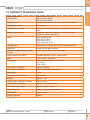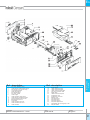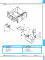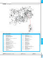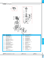
1
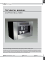
EN
TECHNICAL MANUAL
COFFEE MACHINE
All the parts included in this document are the property of Indesit Company S.p.A.
All rights reserved. This document and the information it contains are supplied without liability for possible
errors or omissions; no part of this document can be reproduced, used or disclosed without written
permission or without being authorised by the terms of a contract clause.
Service Manual
P0055 Coffee Machine - 2006
Edition
2006.08.28
Language
English
EN
CONTENTS OF THIS MANUAL: NOTE FOR THE SERVICE ENGINEER.
This manual is a supporting document for technical personnel. It contains a description of the various
product types, the general operating principle, and indications concerning assistance.
Service Manual
P0055 Coffee Machine - 2006
Edition
2006.08.28
Language
English
2
EN
CONTENTS
1. GENERAL INFORMATION
4-7
PRODUCT KEY
OVERVIEW
INTERFACE
GENERAL INFORMATION
TECHNICAL DATA
4
4
5
5
6
2. OPERATING LOGIC
7-13
OPERATING MODES
USER PROGRAMMING MODE
GROUND COFFEE DOSAGES
FACTORY SETTINGS
WATER CIRCUIT FUNCTIONAL DIAGRAM
SBS DELIVERY VALVE
AQUA PRIMA
7
7
7
8
9
10
12
3. COMPONENTS
14
INTERNAL COMPONENTS
14
4. ELECTRICAL DIAGRAMS
15
WIRING DIAGRAM
15
5. ASSISTANCE
16-35
DIAGNOSTICS MODE
TEST MODE
REMOVING THE OUTER CHASSIS
REMOVING THE CASE AND COMPONENTS SUPPORT
DISASSEMBLING THE COFFEE MACHINE
REMOVING THE BOILERS
CHANGING THE GEARMOTOR
TROUBLESHOOTING
16
17
21
23
26
31
33
35
6. EXPLODED VIEWS
36-41
7. APPENDIX
42
WATER CIRCUIT DIAGRAM
Service Manual
P0055 Coffee Machine - 2006
42
Edition
2006.08.28
Language
English
3
EN
TYPE
1. PRODUCT TYPE:
1.1. PRODUCT KEY:
MCA 16:
MCA 15 NA P:
M=machine
C=coffee
A=automatic
16=index number
M=machine
C=coffee
A=automatic
15=index number
N=North
A=America
P=connection to water supply
1.2. OVERVIEW:
Description of the appliance
6
2
7
8
1
3
4
10
5
12 11
Ref. description
1
2
3
4
5
6
Water tank
Coffee beans hopper
Main power switch
Grind adjustment
Brew unit
Front (control) panel
Service Manual
P0055 Coffee Machine - 2006
9
Ref. description
7
8
9
10
11
12
SBS
Hot water/steam nozzle
Grid
Full tank float
Height adjustable dispenser
Drip tray
Edition
2006.08.28
Language
English
4
EN
TYPE
1.3. INTERFACE
13 14 15
16 17 18 19 20 21
Ref. description
13
14
15
16
17
PROGRAMMING/EXIT select button
PAGES forward button
SELECT/CONFIRM button
DOUBLE COFFEE selection button
LUNGO COFFEE select button
22
Ref. description
18
19
20
21
22
NORMAL COFFEE select button
ESPRESSO select button
HOT WATER select button
STEAM select button
DESCALE select button
1.4. GENERAL INFORMATION:
DOCUMENTATION REQUIRED:
The following technical documentation is required for repairs:
- Instruction booklet of specific model
- Technical documentation of specific model
TOOLS AND EQUIPMENT REQUIRED:
As well as the standard equipment, the following tools are required:
- Torx screwdrivers
- Crosshead screwdrivers
- 1 Digital thermometer with reading range of more than 150°C
- Must be suitable for measurements in liquids and on surfaces
SAFETY WARNINGS:
Before working on the appliance, read the instruction booklet.
Observe all statutory regulations related to repairs of domestic appliances.
Always disconnect the power supply before repairing the appliance;
it is not sufficient to switch off the main power switch to eliminate electric shock hazards.
Service Manual
P0055 Coffee Machine - 2006
Edition
2006.08.28
Language
English
5
EN
TYPE
1.5. PRODUCT TECHNICAL DATA:
Power supply and
consumption:
230 V~; 50 Hz; 1250 W
120 V; 60 Hz; 1250W
100 V; 60 Hz; 1250 W
Safety devices
2 safety thermostats set at 170°C with heat exchanger
Temperature control
NTC sensor
Coffee heating element
Stainless steel heat exchanger - (1090W), for coffee or hot
water.
Steam heating element
Aluminium tube heat exchanger - (1000W) for steam
production (rapid evaporation)
Pump
Ulka vibrating pump;
230V; 50 Hz; 48 W
120V; 60 Hz; 41 W
100V; 50/60 Hz; 55 W
Release valve
Pressurised air release valve with compensation valve
Water filter
Located in the water reservoir
Gearmotor supplementary heating
element
437W - 230 V; 275W - 100/120 V approx.
Coffee grinder (burr plate)
Threaded spindle in brass, ceramic burrs
Motor
230 V / 120 V / 100 V DC
Power draw
During heating: Approx. 5.6 A (230 V);
9 A (120V);
11 A (100V)
Power draw in stand-by
Approx. 20 Watt/h
Cup heater power draw
8 Watt (at operating temperature)
Main pump
15 bar
Dimensions WxDxH (mm)
285/400/375
Weight
Approx. 11 kg
Coffee hopper capacity (in beans)
Approx. 300 gr
Water reservoir capacity
Approx. 2 l at maximum level
Heat exchanger volume
Approx. 1.0 cm3 (10 ml)
Water filling time
Approx. 10 sec. at initial power-on.
Heating time
Approx. 1.5 min
Steam production
Instant
Service Manual
P0055 Coffee Machine - 2006
Edition
2006.08.28
Language
English
6
EN
2. OPERATING LOGIC
2.1. OPERATING MODES:
The appliance can operate in the following modes:
• Diagnostics Mode: this mode allows service
engineers to adjust operating and service
parameters. This menu contains all the user menu
• Test Mode: Used by ser vice personnel to
check operation of the appliance and its main
components.
OPERATION
• User Programming Mode: From the user menu you
can change appliance programming as described
in the instruction booklet.
items plus a series of more complex programming
options reserved for service personnel.
2.2. USER PROGRAMMING MODE
This mode is accessed by means of the menu button (see instruction booklet)
2.2.1. MENU OPTIONS
The following options can be programmed by the
user:
ENERGY SAVING
RINSING
LANGUAGE
CONTRAST
WATER HARDNESS
WATERFILTER
TEMPERATURE
PROGR. COFFEE LENG.
PROGR. WATER AMOUNT
PROGRAM STEAM TIME
AROMA SMALL COFFEE
AROMA COFFEE
AROMA LARGE COFFEE
PREBREWING
TOTAL COFFEES
TIMER
CLOCK
AUTOMATIC ON/OFF
CLOCK TIME
ON/OFF TIME
SHOW CLOCK TIME
2.3. GROUND COFFEE DOSAGES
The coffee dosage depends on the rpm of the coffee
grinder (controlled by a sensor) and the mechanical
grind setting (by means of the adjuster knob).
2.3.1. DOSAGE PROGRAMMING FOR THE USER (AROMA FUNCTION)
You can select the quantity of ground coffee for each
coffee type (espresso, caffé, lungo coffee) by setting
the “Aroma” parameter. This serves to make stronger
or weaker coffee.
Service Manual
P0055 Coffee Machine - 2006
Aroma Type:
• 0: LIGHT (grinder speed of 45 rpm)
• 1: REGULAR (grinder speed of 50 rpm)
• 2: STRONG (grinder speed of 55 rpm).
Edition
2006.08.28
Language
English
7
EN
2.3.2. DOSAGE PROGRAMMING FOR THE ENGINEER
In “Test” mode you can increase the rpm of the coffee grinder in correspondence with each aroma type
(LIGHT, REGULAR, STRONG) by 2.5 rpm.
Level/Aroma type
LIGHT
REGULAR
STRONG
0
1
2
45
47.5
50
50
52.5
55
55
57.5
60
OPERATION
The available levels are as follows:
2.4. FACTORY SETTINGS
The machine is delivered with the following factory
settings:
Temperature level = 2 (Medium)
Water hardness = 3 (High)
Stand-by delay = 3:00
Prebrewing = 1 (short)
Espresso Quantity = 110
Caffé Quantity = 170
Lungo quantity = 290
Espresso Aroma = 1 (Regular)
Caffé aroma = 1 (Regular)
Lungo Aroma = 1 (Regular)
Power-on time = 0:00
Power-off time = 0:00
Display contrast = 6 (60%)
Water filter = 0 (No)
Clock active = 0 (No)
Time visible = 0 (No)
Rinses permitted = 1 (Yes)
Note several factory setting parameters depend on the language set on the appliance:
- if any European language is selected the appliance will present EUROPE settings
- selection of USA English or Canadian French results in US settings.
Espresso Quantity
Caffé Quantity
Lungo Quantity
Service Manual
P0055 Coffee Machine - 2006
EUROPE
USA
110
170
290
110
285
540
Edition
2006.08.28
Language
English
8
EN
2.5. FUNCTIONAL WATER CIRCUIT DIAGRAM
1
2
OPERATION
11
3
4
6
5
Thermostat
heating
element
10
heating
element
8
12
9
hot water / steam
7
Component
1 Water reservoir
2 Float
3 Water filter
4 Turbine
5 Pump
6 Pressure relief valve
7 Heat exchanger / heating
8 Temperature sensor
9 Overtemperature thermostat
10 Hot water / steam supply valve
11 Tubular boiler
12 Steam/hot water solenoid valve
Service Manual
P0055 Coffee Machine - 2006
Function
Water supply
Water empty detection
Elimination of solids from water
Pulse flow measurement, adjusts quantity
Water flowrate / pressure (15 bar)
Protects the water circuit from overpressure conditions (valve opens at 17-19 bar)
Provides heating for delivery of water, coffee and steam
Transmits current temperature values to the electronic control system
In the event of overheating, disconnects appliance power supply
When opened delivers hot water or steam
For steam delivery
Opens if wand is blocked
Edition
2006.08.28
Language
English
9
EN
2.6. SBS VALVE
OPERATION
Beverage dispensing
The SBS delivery valve (see fig. 2), which is
adjustable using the knob, serves to alter (increase
or decrease depending on the knob setting) the
flowrate of water for brewing in the unit.
This serves to alter the coffee brewing time (extraction
time) and consequently the intensity of flavour, while
maintaining the quantity of crema constant.
Fig. 2
Function
With the SBS valve in its open position, an
accumulation of coffee is obtained inside the
diaphragm valve due to the low counter-pressure
of the SBS valve. Consequently the membrane
valve needle remains in the fully open position due
to resistance of the spring. The coffee is delivered
rapidly (see Fig. 3).
With the SBS valve in its closed position, an
accumulation of coffee is obtained on the valve
diaphragm resulting in a pressure build-up inside the
valve. The spring succumbs to the counter-pressure
and the valve element consequently reduces the flow
of coffee (see fig. 4).
Fig. 1
Service Manual
P0055 Coffee Machine - 2006
Fig. 3
Fig. 4
Edition
2006.08.28
Language
English
10
EN
Knob in MAX position
SBS
The difference in delivery rate is approx. 2.5 times
(and therefore VERY obvious!!).
Knob in MED position
SBS
Knob in MIN position
SBS
-> Coffee dispensing
fast
-> Efficient coffee extraction
-> Medium counterpressure
-> Coffee dispensing
medium
-> Efficient coffee extraction
-> Medium-high counterpressure
-> Coffee dispensing
slow
-> Efficient coffee extraction
-> High counterpressure
(Light coffee)
CREME COFFEE
(Medium-strong coffee)
ESPRESSO
(Strong coffee)
RISTRETTO
Service Manual
P0055 Coffee Machine - 2006
Edition
2006.08.28
OPERATION
SBS valve functional check
To check the correct operation of the SBS valve
make a lungo coffee and, while it is being prepared,
check the difference in the rate of delivery from the
maximum to the minimum positions.
Language
English
11
EN
2.7. AQUA PRIMA
If the “aqua prima” function is disabled, the electronic
control system performs a pulse count of the turbine,
recording one pulse every revolution.
If the “aqua prima” function is enabled, the electronic
control system performs a pulse count of the turbine,
recording one pulse every 2 revolutions.
The graph in the figure below illustrates this
function:
OPERATION
If the “aqua prima” filter is selected from the user
menu or the control panel, the system’s water
metering logic functions as follows:
Service Manual
P0055 Coffee Machine - 2006
Edition
2006.08.28
Language
English
12
EN
2. The ion exchanger reduces lime scale deposits
and eliminates heavy metals and suspended
substances from tap water.
3. A special porous filter intercepts undesirable
microparticulate.
4. The corpuscular filter, used as a connection between
reservoir and appliance, filters the water, retaining
any suspended substances and impurities.
As seen in the following graph, the “Aqua Prima” filter
reduces water hardness by up to 50 %.
The water used to brew the coffee is filtered
immediately prior to delivery.
This strategy guarantees that the water is always
optimal for perfect coffee brewing.
The Saeco “Aqua Prima” filter purifies the water in
four stages to achieve truly unique coffee flavour.
OPERATION
The AQUA PRIMA filter
The “Aqua prima” filter is a softener filter that
significantly reduces water hardness, thus reducing
the risk of problems caused by lime scale.
In this context, it should be considered that water
is an essential element in brewing a perfect cup of
coffee, on a par with the coffee blend and roast: the
water must therefore always be perfectly clear and
fresh.
The following section describes the operating modes
and features of the filter.
The “Aqua Prima” filter purifies up to
60 litres of water or around 600 cups
of coffee.
It should be replaced every 3 months.
The need to replace the filter is shown by
an indicator light or display message.
If the machine is not equipped with these
control devices, always observe the expiry
date printed on the filter packaging
All the parts of “Aqua Prima” filter system
are tested for contact with food.
The “Aqua Prima” filter is fully recyclable
and hence environmentally friendly.
The “Aqua Prima” filter packaging
complies with recycling standards as
confirmed by the “green dot” marking.
1. The activated carbon eliminates undesirable
odours and substances from the water, such as
chlorine. The silver coating of the activated carbon
prevents the reproduction of microbacteria.
Service Manual
P0055 Coffee Machine - 2006
Edition
2006.08.28
Language
English
13
EN
3. COMPONENTS:
3.1. INTERNAL COMPONENTS
1
3
COMPONENTS
2
9
4
8
5
6
7
Ref. description
1
2
3
4
5
Coffee grinder
Power Board
Coffee grinder motor
Boiler
Thermostat
Service Manual
P0055 Coffee Machine - 2006
Ref. description
6
7
8
9
Steam boiler
Relief and compensation valve
Pump
Solenoid valve
Edition
2006.08.28
Language
English
14
EN
4. WIRING DIAGRAMS:
WIRING
DIAGRAMS
4.1. WIRING DIAGRAM
Service Manual
P0055 Coffee Machine - 2006
Edition
2006.08.28
Language
English
15
EN
5. ASSISTANCE:
5.1. DIAGNOSTICS MODE
Diagnostics mode includes all the options of the
user programming function plus the “programmer”*
menu, whereby service personnel can access
protected parameters that are not accessible by the
end user.
Some of these parameters are editable, others are
read-only.
To access diagnostics mode:
Switch on the appliance and press the ESPRESSOHOT WATER-ESPRESSO buttons in sequence
within an interval of 3 seconds
DIAGNOSIS-menu
To quit diagnostics mode
Press the menu button one or more times until “selfdiagnostics” is shown on the display. Alternatively
switch off the machine and then switch it on again.
Service Manual
P0055 Coffee Machine - 2006
ASSISTANCE
1 LARGE COFFEE (N°IMPULSES)
1 SMALL COFFEE (N°IMPULSES)
1 COFFEE (N°IMPULSES)
PROGR. WATER AMOUNT
PROGRAM STEAM TIME
PARAMETER K1
PARAMETER K2
TEMPERATURE NORMAL
TEMPERATURE HIGH
TEMPERATURE 1°COFFEE
TOTAL GROUNDS
STOP GROUNDS
TOTAL WATER
WATER DECALCIFY
WATERFILTER
H2O SINCE MSG. DESC.
FLOWRATE l/h
PUMP REGULAT.
WATERRESERVE COUNTER
WATERRESERVE STOP
NUMBER
STATUS
DESCALING NUMBER
DESCALING STATUS
MACHINE STATUS
PRODUCTION DATE DAY
PRODUCTION DATE MONTH
PRODUCTION DATE YEAR
SERVICE DATE DAY
SERVICE DATE MONTH
SERVICE DATE YEAR
*Note: These operations can be performed also by
means of a specific programmer.
Edition
2006.08.28
Language
English
16
EN
5.2. TEST MODE
This menu provides the facility to check operation of
the main components of the machine.
To access test mode:
To access this menu switch the machine on
and select the following sequence STEAM DECALCIFY - STEAM- DECALCIFY within an
interval of 3 seconds.
When you access Test mode a window will be
displayed containing all the information on the
installed software version.
The user can access the various different levels by
pressing the MENU button. The Menu levels can be
consulted in the sequence M1, M2, M3, M4.
Level M2: I/O test
This level allows the user to check the I/O system
(except in relation to the coffee grinder, which is
covered by a separate menu level). The first line
shows a description of the level and a space for
analog information, if present (red circle).
The second line shows the active load on the left
(blue circle) and digital information on the right
(green circle).
Figure 3. Level M2 window.
Figure 1. Test mode opening screen.
Level M1: Keypad test.
ASSISTANCE
This level allows the user to check operation of the
keypad.
The first line shows a description of the level.
The second line briefly shows the number
corresponding to the selected button.
Figure 2. Level M1 window.
Service Manual
P0055 Coffee Machine - 2006
Edition
2006.08.28
Language
English
17
EN
Microswitches and sensors check
DESCRIPTION
ACTIVE
INACTIVE
NOTES
1
Gearmotor WORK
microswitch
Dispenser in
WORK position
Dispenser not in
WORK position
2
Gearmotor HOME
microswitch
Dispenser in
HOME position
Dispenser not in
HOME position
3
Front control panel
microswitch
Panel closed
Panel open
4
GROUNDS
DRAWER
microswitch
Grounds drawer
present
Grounds drawer not
present
5
BREW UNIT
microswitch
Present
Absent
6
DOOR microswitch Door open
7
FLOWMETER
8
WATER LEVEL in
reservoir
Level OK
Level LOW
9
WATER ALARM
microswitch
Presence of
water on base of
machine
No water on base of
machine.
M
Coffee hopper
empty
No coffee present
Coffee must be
present.
This information
is derivative and
not obtained by
hardware.
R
CLOCK
Even seconds
(seconds advance)
Odd seconds
Must flash at 1 HZ
Service Manual
P0055 Coffee Machine - 2006
Door closed
The service engineer
can check the pulses
Edition
2006.08.28
ASSISTANCE
NUMBER
Language
English
18
EN
Check COMPONENT FUNCTIONS
BUTTON
FUNCTION
Note: certain loads are equipped with safety
devices that may deactivate them to avoid possible
damage.
SAFETY
INFORMATION
UP
The brew unit moves up
WORK microswitch must be
deactivated.
The grounds drawer
microswitch must be active.
The door must be closed
Motor current [mA]
DOWN
The brew unit moves
down
HOME microswitch must be
deactivated.
The grounds drawer
microswitch must be active.
The door must be closed
Motor current [mA]
OK
Coffee boiler heating
element powered
DOUBLE COFFEE
Steam boiler heating
element powered
LUNGO COFFEE
Pump *
No water supplied
CAFFÉ
Pump + water supply
solenoid valve *
Water supplied
ESPRESSO
Water supply valve
HOT WATER
Display backlighting
STEAM
Display contrast
DECALCIFICATION
Water supply solenoid
valve
Temperature [°C]
ASSISTANCE
The user can activate functions by pressing the
buttons as shown in the following table. To deactivate
functions, press any button.
The active load is displayed on the second line (blue
circle).
*Note: in the plumbed-in configuration the water supply solenoid valve opens automatically when the pump
is started.
Service Manual
P0055 Coffee Machine - 2006
Edition
2006.08.28
Language
English
19
EN
Level M3: Tests on coffee grinder
This level allows the service engineer to check
operation of the coffee grinder.
The first line shows a description of the level and a
space for analog information, if present (red circle).
The second line shows whether or not the load is
active (blue circle). Additional information is shown
in the red circle and the flashing “X” (green circle).
When the coffee grinder is operating (UP button) the
speed is shown in rpm (red circle ) and the “X” flashes
(green circle).
“v” can show one of the Aroma levels: 0 - 1 - 2 (see
heading 2.3.2). The value can be edited with the
DOWN button and saved by pressing OK.
If the value has been edited but not saved the
“*” symbol will be displayed at the end of the second
line. When the value is saved, the “*” symbol
disappears.
Figure 2. e.g.: only jumper JP27 present
Note: the presence of JP27 is required for the
plumbed-in configuration: in this case the “water
connection” option appears automatically in the
user menu, although it must still be activated if it is
to be used.
How to quit Test mode.
Switch off the machine and then switch it on again.
ASSISTANCE
Level M4: Jumpers
In this section you can check the jumper configuration,
i.e. the presence or absence of certain jumpers.
Figure 1. e.g.: all jumpers present
Service Manual
P0055 Coffee Machine - 2006
Edition
2006.08.28
Language
English
20
EN
1. Remove the drawer
4. Open the front door and remove the coffee assy
by pressing the button shown in the photo
2. Remove the drawer support
5. Remove the screws shown in the photo
B
B
ASSISTANCE
5.3. DISASSEMBLY OF THE OUTER CHASSIS
A
A
3. Undo screws “A”
Service Manual
P0055 Coffee Machine - 2006
6. Undo screws “A” and press the interlocking tabs
then push them outwards (this operation must be
performed also on the other side of the chassis)
Edition
2006.08.28
Language
English
21
EN
10. To remove the gear for opening of the front panel
detach the spring and withdraw the gear
ASSISTANCE
7. Slide the appliance out of the outer chassis as
shown in the photo
8. Undo the screw shown in the photo to remove the
LH insert
9. Undo the screws shown in the photo to remove
the RH insert
Service Manual
P0055 Coffee Machine - 2006
Edition
2006.08.28
Language
English
22
EN
5.4. REMOVING THE CASE AND COMPONENTS SUPPORT
1. Undo the screws shown in the photo on the RH
and LH sides
ASSISTANCE
Clip
2. Undo the screws (shown above and right) and
detach the steam hose by removing the Clip.
3. Undo the screws shown in the photo at the rear
of the machine
Service Manual
P0055 Coffee Machine - 2006
4. Remove the cover as shown in the photo
Edition
2006.08.28
Language
English
23
EN
A
C
B
ASSISTANCE
5. Remove wire tie “B” and extract connector “A” and Fastons “C”
6. Lift the components suppor t clear of the
chassis
7. Chassis
Service Manual
P0055 Coffee Machine - 2006
8. Plate
Edition
2006.08.28
Language
English
24
EN
ASSISTANCE
9. Remove the wire tie
10. Remove the upper plate by lifting it
Service Manual
P0055 Coffee Machine - 2006
Edition
2006.08.28
Language
English9
25
EN
5.5. REMOVING THE COFFEE GRINDER
1
2
ASSISTANCE
1. Undo the screws shown by the arrow (Note: When
reassembling the coffee grinder remember to refit
the two vibration dampers “1” which are wrapped
around motor “2”)
2. Remove the coffee grinder
3. When reassembling the coffee grinder use caution
when repositioning the seal shown in the photo
Service Manual
P0055 Coffee Machine - 2006
Edition
2006.08.28
Language
English
26
EN
Disassembling the grinder burrs
released
A
D
(upper burr disassembly)
Once the burr is detached it can be removed from
its support.
ASSISTANCE
B
C
4 To remove the upper burr “A” (disassemble the
pack) turn it counterclockwise as shown in the first
photo, with the aid of the ringnut “B” until tooth “C”
is aligned with slot “D”
Service Manual
P0055 Coffee Machine - 2006
Edition
2006.08.28
Language
English
27
EN
released
After releasing the lower burr it can be removed from
the relative support.
(lower burr disassembly)
Remove all coffee residues with a small flat-bladed
screwdriver, a jet of compressed air, and a vacuum
cleaner.
Rotate the burr anticlockwise, using a small flatbladed screwdriver to prise it off as shown in the
first figure.
Service Manual
P0055 Coffee Machine - 2006
The upper and lower burrs are made of ceramic
material and are identical.
N.B:
To reassemble the burrs perform the disassembly
steps in reverse sequence
Edition
2006.08.28
ASSISTANCE
blocked
Language
English
28
EN
1. Undo the four fixing screws of the motor flange.
4. Remove the sensor from the flange seat by pressing
on the anchoring tab.
2. Remove the sensor support from the flange seat
with the aid of a small screwdriver (as shown in
the figure).
5. Disconnect the motor power cables.
ASSISTANCE
Disassembly of the coffee grinder motor
6. If the gear is damaged, remove it using a 10 mm
wrench and a 7 mm wrench to unscrew the
locknut.
3. Remove the rubber plug from the motor flange.
Service Manual
P0055 Coffee Machine - 2006
Edition
2006.08.28
Language
English
29
EN
7. Fit the new gear and mesh it with the spindle pinion;
now secure the gear with the washer and locknut.
11. Apply grease also to the teeth of the worm gear
on the grinder motor shaft.
12. Couple the motor flange with the rest of the unit
as shown in the figure.
ASSISTANCE
8. Tighten the nut onto the brass spindle shaft with
the 7 and 10 mm wrenches.
9. Apply grease to all the gear teeth..
10. Smear the grease uniformly and generously over
the entire gear.
Service Manual
P0055 Coffee Machine - 2006
13. Insert the locking pins as shown in the figure and
press them fully home.
Edition
2006.08.28
Language
English
30
EN
5.6. REMOVING THE BOILERS
Steam boiler
A
D
B
D
1. Undo screw “A” and the two nuts “B”. Remove the two Teflon hoses.
Remove the heating element protection “C” and detach the two Faston connectors “D”.
2. To remove the steam boiler unscrew the locknuts
and withdraw the Teflon hoses.
Service Manual
P0055 Coffee Machine - 2006
ASSISTANCE
C
3. Undo the screw shown in the photo
Edition
2006.08.28
Language
English
31
EN
1. To remove the coffee boiler undo the three screws
shown in the photo.
4. Remove the Fastons of the safety thermostats
2. Remove the boiler from the plate assy.
5. To replace the thermostats loosen the screw
shown in the figure
3. Remove the 4 Faston connectors from the heating
element terminals
Service Manual
P0055 Coffee Machine - 2006
ASSISTANCE
Coffee boiler
6. Remove the fixing clip and remove the Teflon hose
that connects the pump to the boiler
7. The photo on the right shows the boiler
disassembled from the plate.
Edition
2006.08.28
Language
English
32
EN
5.7. CHANGING THE GEARMOTOR
A
E
B
F
G
1. Remove cover (A) by undoing the three screws.
A
C
B
2. Undo the two screws and remove boiler spigot (B)
4. The following parts are accommodated inside the
compartment protected by the chassis:
- electric motor (A) with gears (B) and (C) for
transmission and timing of the brew unit;
- grounds drawer presence microswitch (D);
- brew unit presence microswitch (E);
- microswitch (F) responsible for detecting the rest
position of the brew unit;
- microswitch (G), responsible for detecting the
delivery phase of the brew unit.
Withdraw gear (C) that meshes with the motor
transmission shaft.
Remove the large diameter gear (B).
Pull out motor (A) complete with transmission
shaft (H).
ASSISTANCE
D
C
3. Remove protection plate (C) by undoing the
screws.
Service Manual
P0055 Coffee Machine - 2006
Edition
2006.08.28
Language
English
33
EN
A
H
C
L
5. Install the motor and drive shaft, fitting guides (L)
in their location
8. Refit protective cover (C) and secure with the relative
screws
G
B
D
B
P
6. Fit gear (B), taking care to ensure that the arrow
stamped on the gear is within the opening
containing pin (P).
7. Fit the gear that meshes with the transmission
shaft.
Service Manual
P0055 Coffee Machine - 2006
9. Refit boiler spigot (B) taking care to check that both
seals (G) are present on the nozzle that is inserted
in the bore on pipeline (D).
ASSISTANCE
L
Tighten the boiler spigot screws.
Warning: snug both screws fully before tightening
them
Edition
2006.08.28
Language
English
34
EN
5.8. TROUBLESHOOTING
PROBLEMS
CAUSES
SOLUTIONS
The machine fails to switch
on
The machine is disconnected
from the power supply
Check the connection to the power
supply.
Coffee is insufficiently hot
Cups are cold
Warm cups with hot water.
No hot water or steam
supplied
Steam wand blocked
Extract steam wand by pulling
downwards and then wash it.
Coffee is delivered too
slowly
Coffee grind is too fine
Brew unit dirty
Change coffee blend
Turn grind adjustment knob to a
higher value setting.
Wash the brew unit.
Coffee is delivered rapidly
SBS system knob turned to right
Turn knob to the left and then to
the right , when the machine starts
delivering coffee.
Coffee grind is too coarse
Change coffee blend.
SBS system knob turned to left
When the machine starts delivering
coffee turn the knob to the right.
The machine takes a long
time to heat up and the
quantity of water delivered
from the wand is limited.
Scale build-up in machine circuit
Perform decalcification procedure.
The brew unit cannot be
removed
The brew unit is not in position
Switch the machine on. Close
the front door; the unit will return
to its initial position and it can be
extracted.
Drip tray fitted.
Remove the drip tray.
Coffee leaks to the exterior
of the dispenser.
Dispenser in incorrect position
Repositionthe dispenser.
Dispenser clogged
Remove the dispenser and wash.
The coffee has insufficient
crema
The blend is not suitable or the
coffee is not freshly roasted.
Change coffee blend.
The coffee grind is too coarse
Adjust the grinder settings.
SBS system knob turned to left
Turn the SBS system knob towards
the right.
Drip tray too full
Check the position of the float and
empty the drip tray.
Water leaking from drip tray
Service Manual
P0055 Coffee Machine - 2006
Edition
2006.08.28
ASSISTANCE
Set the grind adjuster knob to a
lower value.
Language
English
35
EN
0
1
2
3
4
5
6
9
10
11
12
13
14
15
16
17
18
19
20
instruction manual
coffee machine chassis
coffee machine left upright
enclosure lower/upper insert
enclosure side/rear insert
water recovery tray cover
enclosure side/front insert
coffee machine right upright
torx screw, galvanized 2.9x6.5
washer d11 x 0.8
torx screw, k 35x16
lower chassis coffee machine
LH handle
water recovery tray fixing pin clip
water recovery tray fixing pin
water recovery tray fixing pin cap
coffee machine rear panel
torx screw, m 5x20
coffee machine containers support
Service Manual
P0055 Coffee Machine - 2006
Ref. description
21
22
23
24
25
26
27
28
29
31
32
33
34
35
36
37
38
39
power cable 3x1 ho5rr l=1500
“aqua prima” water filter
torx screw, k 30x12
torx screw, k 30x8
RH handle
coffee grounds drawer
water recovery inner tray assy.
ariston water recovery tray
water recovery tray insert
water recovery tray float
water recovery tray grille
enclosure central insert
pin support w/toothed sector
rotation pin
rotation pin clip
torx screw, k 30x8 wn 1452
caphead torx screw, tx10 3.5x8.5
flathead screw, 3.5x9.5 din 7982 s/steel
Edition
2006.08.28
VIEWS
Ref. description
EXPLODED
6. EXPLODED VIEWS
Language
English
36
EN
torx screw, m 3x20 iso 14580
washer, uni 8842 a3 s/steel
torx screw, m 3x8 din 7500
torx screw, k 30x8 wn 1452
washer, uni 8842 a6
door hinge bush
door inner plate
coffee delivery hose rear plug
coffee delivery hose seal
coffee delivery hose
coffee dispenser support
coffee dispenser seal (h2.5)
door button support
door button clip
door button
torx screw, k 30x8
Teflon hose holder insert
joint support
O-ring 117 silicone
semi-spherical seal
torx screw, m 4x10 head d=8x1.5
door hinge assy
O-ring metric 0040-20
crema adjusting rod
crema adjusting rod clip
Service Manual
P0055 Coffee Machine - 2006
Ref. description
28
29
30
31
32
33
34
35
36
37
38
39
40
41
42
43
44
45
46
47
48
49
50
51
52
crema adjusting rod support
crema adjusting knob
torx screw, m 2.5x5 din 7500
coffee delivery retaining insert cover
spring for coffee dispenser
coffee dispenser retaining insert
coffee dispenser rear cover
crema adjusting knob
threaded union for coupling
door
steam wand fixed ball joint
steam wand mobile ball joint
O-ring, metric 0060-20
steam wand protection
upper pipe for ball joint
O-ring 108
inner lower sleeve
sleeve outer cover
coffee dispenser button
coffee dispenser front cover
coffee dispenser inner body
coffee dispenser mobile section assy.
coffee dispenser mobile section
coffee dispenser sponge
coffee dispenser sponge support
Edition
2006.08.28
VIEWS
1
2
3
4
5
6
7
8
9
10
11
12
13
14
15
16
17
18
19
20
23
24
25
26
27
EXPLODED
Ref. description
Language
English
37
1
2
3
4
5
6
7
8
9
10
11
12
13
14
15
16
torx screw, k 30x8 wn 1452
coffee machine main PCB w/connect
level sensor 2-pin connector assy.
control PCB protection
water valve support
tray terminal board
torx screw, k 30x8
coffee hopper
coffee container closing insert
coffee machine containers support
plug for flat cable channel cover
flat cable channel cover
microswitch
coffee container rear cover
coffee container front cover
coffee container
Service Manual
P0055 Coffee Machine - 2006
Ref. description
17
18
19
20
21
22.
23
24
25
26
27
28
29
30
31
32
levers support
coffee container LH lever
coffee container RH lever
coffee container closing plate
torx screw, k 25x8 wn 1452
display PCB
coffee machine front panel
programmer cover
programmer cover seal
switches cover
push-push button
front panel insert
front panel support
front panel support seal
2 flat-cables (10p and 14p) assy.+ seal
dual pole switch
Edition
2006.08.28
VIEWS
Ref. description
EXPLODED
EN
Language
English
38
Ref. description
1
2
3
4
5
6
7
8
9
10
coffee machine container support
turbine support
microswitch pin clip
front panel rotation pin
water container rear cover
water container cover
water container front cover
float assy, w/magnet
float support
water valve union
Service Manual
P0055 Coffee Machine - 2006
VIEWS
EXPLODED
EN
Ref. description
11
12
13
14
15
16
17
18
19
20
Teflon hose 5x7 l=60 mm
water container external filter assy.
O-ring metric 0019-10
water filter support
water filter support union
water container
O-ring metric 0060-30
water container valve piston
water valve seal
water container valve cylindrical spring
Edition
2006.08.28
Language
English
39
EN
90° pump inlet union
hose clip d=9.5mm
silicone hose 5x8 70sr
pump support eaton magic
ulka pump ep5/s gw 230v-50hz
2-pole pump connector
O-ring 2031
compensation valve assy. and 16 bar relief valve
hose clip d=4
O-ring 2015 silicone
torx screw, k 35x16
pump support
silicone hose 5x10 60 shore
Teflon union-nut-prot. assy. 200mm
caphead screw, m4x8 uni 7687
fuse holder plate
single core silicone lead, blue awg16 100 mm
heating element protection
thermostat 175°
heating element, bleckman 230v
Teflon union+protect.2x4 120mm
caphead screw, ph/tt 4x8 uni 8112
hose union d=4 1/8
2-way solenoid valve 1/8” m4 24v 19w
black silicone hose 7.5x9.3
torx screw, k 35x12 wn 1423
straight union w/support
straight union
hose clamp
clip d=7.5 for braided hose 3x7
Service Manual
P0055 Coffee Machine - 2006
Ref. description
34
35
36
37
38
39
40
41
42
43
44
45
46
47
48
49
50
51
52
53
54
56
57
58
59
60
61
62
63
braided silicone hose
hose union
torx screw, m 5x20
nut, metalbloc m5x0.8 din 980
wiring+microswitch
caphead Allen screw 10.9 m5x20
turbine
assembly plate w/pin
boiler spigot cap
O-ring metric 0060-20 silicone
needle spring
piston w/groove l=20.9
silicone hose 5x8
torx screw, k 30x12
boiler spigot
O-ring orm 0090-20
O-ring orm 0050-20
spool for boiler valve
thermostat holder clip
spring protection
thermostat 175°
Teflon union+nut+prot. l=220mm
boiler assy. w/out heating element 230v
Tee union d8
boiler support
Teflon union+nut+prot. l=120mm
boiler support square
temperature sensor - ntc
boiler spigot union
Edition
2006.08.28
VIEWS
1
2
3
4
5
6
7
8
9
10
11
12
13
14
15
16
17
18
19
20
24
25
26
27
28
29
30
31
32
33
EXPLODED
Ref. description
Language
English
40
EN
increase screw
coffee grinder upper support
O-ring metric 0530-15
ceramic burr 48x28
increase screw pin m4-m6
ceramic burr lower support
thrust bearing
felt ring od=45.4 id=39.4 h=4
ground coffee outlet support body
balancing washer 21.8x14x0.25
radial bearing
grinder burr drive gear
coffee grinder pulse sensor
coffee grinder motor assy 230v
thermal sensor support
lock nut m4 din982
plain washer id=4.3 od=14 thk. =1.5
caphead screw 3.5x30 d.7505
worm gear auger central cap
coffee outlet shroud cover
coffee outlet shroud assy.
caphead screw m4x8 uni 7687
grind fineness adjuster knob
adjusting pin
ball clip
s.steel ball d=3.2mm
coffee grinding adj. lower support
bevel gear z=39 grind adjust.
Service Manual
P0055 Coffee Machine - 2006
Ref. description
29
30
31
32
33
34
35
36
37
38
39
40
41
42
43
44
45
46
47
48
49
50
51
52
53
54
55
spindle retaining ring d=3.2
ring 4 uni 7434
grind adjust. worm gear
torx screw, k 35x16
grind adjust taper pin
motor locking flange
motor support seal
coffee grinder seal
coffee grinder motor 230v
motor antivibration seal
motor support
torx screw, k 35x12 wn 1423
assembly plate w/pin
microswitch
assembly plate
gear
gearmotor mylar washer
bakeliz. washer d=5.5
gearmotor bush
assembly plate cover
microswitch support
torx screw, k 30x8 wn 1452
drive motor
antivibration mount for motor
microswitch
boiler compartment cover
smart coffee unit
Edition
2006.08.28
VIEWS
1
2
3
4
5
6
7
8
9
10
11
12
13
14
15
16
17
18
19
20
21
22
23
24
25
26
27
28
EXPLODED
Ref. description
Language
English
41
EN
7. APPENDIX:
APPENDIX
Water circuit diagram
Service Manual
P0055 Coffee Machine - 2006
Edition
2006.08.28
Language
English
42
EN
Indesit Company
viale Aristide Merloni, 47
60044 Fabriano - Italy
tel. +39 0732 66 11 - telex 560196 - fax +39 0732 66 2954 - www.indesitcompany.com
Service Manual
P0055 Coffee Machine - 2006
Edition
2006.08.28
Language
English