1
SSA-P400
SSA-P400T
SSA-P401
SSA-P401T
Access Control Panel
user manual
imagine the possibilities
Thank you for purchasing this Samsung product.
To receive more complete service,
please visit our website.
www.samsungsecurity.com
safety information
CAUTION
RISK OF ELECTRIC SHOCK.
DO NOT OPEN
CAUTION: TO REDUCE THE RISK OF ELECTRIC SHOCK, DO NOT REMOVE COVER (OR BACK) NO USER SERVICEABLE
PARTS INSIDE. REFER SERVICING TO QUALIFIED SERVICE PERSONNEL.
This symbol indicates that dangerous voltage consisting a risk of electric shock is
present within this unit.
This exclamation point symbol is intended to alert the user to the presence of
important operating and maintenance (servicing) instructions in the literature
accompanying the appliance.
WARNING
• To reduce the risk of fire or electric shock, do not expose this appliance to rain or moisture.
WARNING
1. Be sure to use only the standard adapter that is specified in the specification sheet.
Using any other adapter could cause fire, electrical shock, or damage to the product.
2. Incorrectly connecting the power supply or replacing battery may cause explosion, fire, electric shock, or damage to
the product.
3. Do not connect multiple controllers to a single adapter. Exceeding the capacity may cause abnormal heat generation or fire.
4. Securely plug the power cord into the power receptacle. Insecure connection may cause fire.
5. When installing the controller, fasten it securely and firmly. The fall of controller may cause personal injury.
6. Do not place conductive objects (e.g. screwdrivers, coins, metal parts, etc.) or containers filled with water on top of the
controller. Doing so may cause personal injury due to fire, electric shock, or falling objects.
7. Do not install the unit in humid, dusty, or sooty locations. Doing so may cause fire or electric shock.
8. If any unusual smells or smoke come from the unit, stop using the product. In such case, immediately disconnect the
power source and contact the service center. Continued use in such a condition may cause fire or electric shock.
9. If this product fails to operate normally, contact the nearest service center. Never disassemble or modify this product in
any way. (SAMSUNG is not liable for problems caused by unauthorized modifications or attempted repair.)
10.. When cleaning, do not spray water directly onto parts of the product. Doing so may cause fire or electric shock.
CAUTION
1. Do not drop objects on the product or apply strong blows to it. Keep away from a location subject to excessive
vibration or magnetic interference.
2. Do not install in a location subject to high temperature (over 50°C), low temperature (below 0°C), or high humidity.
Doing so may cause fire or electric shock.
3. If you want to relocate the already installed product, be sure to turn off the power and then move or reinstall it.
4. Remove the power plug from the outlet when there is a lighting storm. Neglecting to do so may cause fire or damage
to the product.
2_ safety information
5. Keep out of direct sunlight and heat radiation sources. It may cause fire.
6. Install it in a place with good ventilation.
7. Avoid aiming the controller directly towards extremely bright objects such as sun.
8. Apparatus shall not be exposed to dripping or splashing and no objects filled with liquids, such as vases, shall be
placed on the apparatus.
9. The Mains plug is used as a disconnect device and shall stay readily operable at any time.
FCC Statement
1) This device may not cause harmful interference, and
2) This device must accept any interference received including interference that may cause undesired operation.
Caution
This equipment has been tested and found to comply with the limits for a Class A digital device, pursuant to part
15 of FCC Rules. These limits are designed to provide reasonable protection against harmful interference when
the equipment is operated in a commercial environment.
This equipment generates, uses, and can radiate radio frequency energy and, if not installed and used in accordance with the instruction manual, may cause harmful interference to radio communications. Operation of this
equipment in a residential area is likely to cause harmful interference in which case the user will be required to
correct the interference at his own expense.
IMPORTANT SAFETY INSTRUCTIONS
1. Read these instructions.
2. Keep these instructions.
3. Heed all warnings.
4. Follow all instructions.
5. Do not use this apparatus near water.
6. Clean only with dry cloth.
7. Do not block any ventilation openings. Install in accordance with the manufacturer’s instructions.
8. Do not install near any heat sources such as radiators, heat registers, or other apparatus (including amplifiers) that
produce heat.
9. Do not defeat the safety purpose of the polarized or grounding-type plug. A polarized plug has two blades with one
wider than the other. A grounding type plug has two blades and a third grounding prong. The wide blade or the third
prong is provided for your safety. If the provided plug does not fit into your outlet, consult an electrician for
replacement of the obsolete outlet.
10. Protect the power cord from being walked on or pinched particularly at plugs, convenience receptacles, and the
point where they exit from the apparatus.
11. Only use attachments/accessories specified by the manufacturer.
12. Use only with cart, stand, tripod, bracket, or table specified by the manufacturer, or sold with
the apparatus.
13. Unplug this apparatus when a card is used. Use caution when moving the cart/ apparatus
combination to avoid injury from tip-over.
14. Refer all servicing to qualified service personnel. Servicing is required when the apparatus has been damaged in any
way, such as powersupply cord or plug is damaged, liquid has been spilled or objects have fallen into the apparatus,
the apparatus has been exposed to rain or moisture, does not operate normally, or has been dropped.
English3
SAFETY INFORMATION
This device complies with part 15 of the FCC Rules. Operation is subject to the following two conditions :
contents
5
7
12
Features
What’s included
Cable Selection
13
13
14
15
18
Connecting the termination resistor and
diode
Earth-grounding the communication cables
Power, Reader, and I/O Connection
Communication Line Connection
INITIALIZATION
22
23
System Initialization
Board ID Setting
24
Troubleshooting
26
Product Specifications
PRODUCT INTRODUCTION
5
INSTALLATION AND EXTERNAL
CONNECTION
22
TROUBLESHOOTING
24
PRODUCT SPECIFICATIONS
26
4_ contents
product introduction
FEATURES
State-of-the-art Access Controller
Standalone Operation
By connecting to 4 card readers, you can use this product to control the access of the maximum of 4 doors. This
controller determines to allow access by reading data from the card reader, and controls the open/close of the
door relay and enables you to change other output settings. Upon receipt of an incoming external input signal
(sensor or Exit button), it launches an output device such as the relay. This controller has an independent control
system, assuring a normal operation regardless of problems on any other systems and, not affecting them in the
reverse situation.
Anti-Pass Back
A door has two card readers installed: one for the entrance, and the other for the exit, so anyone who enters
should recognize his/her card on the reader at the entrance time before he can exit normally. If a person does not
go under the card recognition process and just follows another person’s way inside the door, the person is not
allowed to exit when he/she recognizes the access card on exit card reader, and the anti-pass-back error (APB
error) occurs which will be saved into the internal memory. And you can configure to output a certain signal through
a specific port if such an error occurs. (Make your setting using the Application program (controlled access, time
and attendance management, etc) – I/O Setup – APB Error) You can use Anti-Pass Back for controlling two doors
independently or in synchronization with each other.
Computer-based Management
All records of authorized or unauthorized accesses and any external signal will be saved in the internal memory.
You can download such data onto your computer according to the specified communications protocol. With the
downloaded data, you can store, process, and create a report based on your query (access and alert details, etc)
on the central computer.
Door Count Setup (2/3/4 doors)
As it is equipped with 4 card readers, you can use this product to control the access on a maximum of 4 doors.
For controlling 2 doors, install reader 1 and reader 2 on door 1 while installing reader 3 and reader 4 on door 2. For
controlling 3 doors, install reader 1 and reader 2 on door 1 while installing reader 3 on door 2, and reader 4 on
door 3. For controlling 4 doors, install one reader on each door, totalling 4.
English5
PRODUCT INTRODUCTION
SSA-P400(T)/SSA-P401(T) is a state-of-the-art door access controller device that provides a high level security
system in an affordable price, meeting the needs in the security industry.
SSA-P400(T)/SSA-P401(T) can control access of 2-4 doors with simple manipulation and high level stability as well
as its affordable cost.
You can specify up to 1000 ~ 20,000(30,000/ 40,000/50,000) instances of card registration to your preference,
which you can delete or change as necessary. The built-in event memory can save up to 20,000 ~ 29,500(14,000/
8,000/3,000) instances of entires and alerts according to the number of registered cards.
You can connect a wide range of readers via the 4 reader ports, and operate the reader in either RF Card or RF
Card + PW mode.
15 independent input ports can be used to connect to various devices such as Exit Button, Door Contact Sensors,
PIR Sensors, and Window Breakage Sensors to reinforce security.
You can use the keypad (optional) to configure your settings with easy.
You can establish the independent or network connection via RS-232 or RS-422 communications. SSA-P400(T)/
SSA-P401(T) is equipped with a built-in TCP/IP module, which enables you to establish LAN communications. All
settings including card registration information, I/O settings, Real Time Clock, Time Schedules and all Event
Transaction Reports can be downloaded /uploaded from/to the host computer with software supporting a variety
of reporting formats.
Installed and managed inside the security zone for preventing the risk of damage, SSA-P400 (P401) can implement
a high level security access control system with multiple control options, best fit for access control and time &
attendance management.
product introduction
Input Port Format Setup
15 input ports are provided by default. For these ports, you can specify if the format of the incoming signal is
blocked (NO) or connected (NC) in normal operation. This setting will make all ports operate same regardless of the
output status of the input device.
Time Scheduling
You can specify a time range during which a specific operation is performed. You can specify a specific time range
for a schedule code, which will be transferred to the applicable device. You can specify up to 5 different time
intervals for a day, ranging from Monday to Sunday including holidays. Each time schedule code can produce a
single different (or same) holiday code.
Door Open Alarm and Forced Door Open Alarm
The Door Open Alarm function notifies the administrator that the door is still open if a door stays open after the
normal door open time and the standby time. (The output signal can be transferred via the output port, data on any
abnormal state will be stored in memory, which will be transferred upon request from the PC software. The Forced
Door Open Alarm function produces an alert when the door is forced to open and makes an alert again if the door
is still open after the timeout.
I/O Settings
This product is equipped with 15 input ports, 12 relay output ports, and 3 TTL output ports. You can use the
input ports to receive signals from the Exit button and the fire sensor, and utilize this product to meet various
situations such as attaching the door lock to any of the 12 relays. You can also set the output time for these
output ports.
Holiday Setup
You can specify a holiday (legal holiday or bi-weekly holiday) excluding Sunday. You can specify up to 100 holidays
for a single holiday code. (Access can be permitted only for an allowable time range according to your time
schedule setting) A holiday code can be assigned to the time schedule code.
ARM/DISARM
In the condition where the ARM/DISARM code is specified, if you enter the ARM/DISARM code and present the
card of the administrator (with master permissions) to the reader, the device triggers the alarm mode where you
can control the output signal in sync with the security system. In this mode, all connected readers will not take the
card input any further.
Duress Mode
This is used in a situation where you should open the door inevitably by a robber insisting to do so. Open the door
by entering the two-digit duress alarm password and pressing the
button before presenting the registered card
(or recognizing the card number), in the meantime this forcibly duress situation will be notified to the PC application.
Two Men Operation Mode
This will allow access by visitors only under the control of the visitor guide.
Access will be permitted only if two cards are presented within a specified time (10 seconds).
Dual Door Time Control
This allows you to specify two different settings for the entrance door control time according to the passers-by.
However, this can not be enabled with the ARM/DISARM function at the same time.
Data Maintenance
In the event of power failure, the controller retains all card information and the access/alert history (event data) until
it is damaged on the memory.
J
You can use the application program (SAMS Basic) to configure all theses settings to your preference.
6_ product introduction
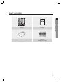
WHAT’S INCLUDED
Check if the following items are included in the product package.
PRODUCT INTRODUCTION
xGn
Main Unit
Quick Guide
CD Manual
Diode (x12)
(UF4004, 1N4001~4007)
English7
product introduction
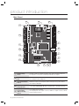
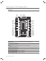
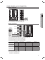
Main Board
1
2
3
24
25
4
23
22
16
5
21
17
6
20
15
7
19
10
8
18
9
14
13 12 11
The address number specified by the address setup switch should match that of the
host computer as it is used for communications with the host computer.
1
Board ID Setup
Switch
2
I/O Board Connection Communication ports to connect to the I/O board, which include Input #8 through Input
Port
#15 and Output #8 through Output #15.
3
System Initialization
Switch
Pressing both of the switches at the same time for about 2 seconds will sound
initialization ready beep. Releasing both switches will stop the beep, and restarts the
system after the initialization.
4
Output (Relay #1 ~
Relay #4) Ports
4 relay outputs (FORM-C(COM, NO, NC)) are provided. (DC12~18V, Max Current 2A)
5
Output (TTL #1 ~
TTL #3) Ports
Address Setup
Switch
3 TTL output ports are provided.
The voltage depends on the output occurrence, DC 0V for no output occurrence, and DC
5V for any output occurrence.
8_ product introduction
RJ-45
Connect the LAN cable for TCP/IP communications.
7
RS-232
Communication
Port
One RS-232 communication port is provided. Used to exclusively connect to a PC in a
local area.
8
RS-422
Communication
Port
9
Power Connection
Port
10
LED Extension Port
Port used to extend the power and communication indicators so that they can display
in an external device.
11
TCP/IP Module LED
Indicator
For TCP/IP module communications, the status of the TCP/IP module will be provided
additionally.
12
Power LED Indicator Power connection status indicator. It always stays ON while the power is applied.
13
Output LED
Indicator
14
Keypad Connection
Optional item.
Port
15
LCD Connection
Port
Optional item.
16
TCP/IP Module
Connection Port
The TCP/IP module is optional so it is not provided by default. Communication can be
established using the built-in TCP/IP module. Communication with the PC can be
established using the built-in TCP/IP module.
17
Firmware ROM
This must be replaced before the firmware update; you can check the current firmware
version.
18
Reader #1 Port
The first reader connection port.
19
Reader #2 Port
The second reader connection port.
20
Reader #3 Port
The third reader connection port.
21
Reader #4 Port
The fourth reader connection port.
22
Input LED Indicator
Indicates the status of the incoming signal to the input port. A flashing indicator denotes
the occurrence of any signal to the input port (NC-type input device). In the NO-type
connection, the LED indicator turns on if no sensor signal occurs while it turns off if any
signal occurs.
23
Input Ports
(Input #1 ~ #7)
Input ports #1 ~ #7.
24
Fixing Hole
Fixing hole used to install the product through the bezel, using screws.
25
Buzzer
It will sound beeps on system initialization to the configured output depending on the
buzzer control settings.
One RS-422 communication port is provided.
You can establish up to 32 multi-drop communications.
DC +12V is used for the power source.
Output status indicator for the output port. A flashing indicator denotes the occurrence
of any output.
English9
PRODUCT INTRODUCTION
6
product introduction
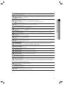
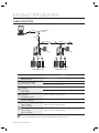
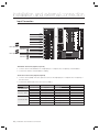
I/O Board
1
2
19
3
20
4
18
5
17
6
16
7
15
8
14
21
13
12
9
10
11
1
Fixing Hole
Used to fix the main board to the I/O board using screws.
2
Power LED Indicator
The red indicator turns on in the normal power supply condition.
3
Main Board Connection
Port
Connector used to connect to the main board.
4
Output (Relay #5) Port
Output port #5.
5
Output (Relay #6) Port
Output port #6 (FORM-C).
6
Output (Relay #7) Port
Output port #7 (FORM-C).
7
Output (Relay #8) Port
Output port #8 (FORM-C).
10_ product introduction
INPUT #8
Input port #8.
9
INPUT #9
Input port #9.
10
INPUT #10
Input port #10.
11
INPUT #11
Input port #11.
12
INPUT #12
Input port #12.
13
INPUT #13
Input port #13.
14
INPUT #14
Input port #14.
15
INPUT #15
Input port #15.
16
Output (Relay #9) Port
Output port #9 (FORM-C).
17
Output (Relay #10) Port
Output port #10 (FORM-C).
18
Output (Relay #11) Port
Output port #11 (FORM-C).
19
Output (Relay #12) Port
Output port #12 (FORM-C).
20
Output LED Indicator
LED Indicator that indicates the output status.
21
Input LED Indicator
LED Indicator that indicates the input status.
PRODUCT INTRODUCTION
8
English11
product introduction
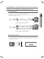
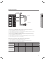
CABLE SELECTION
RS-232
RS-422/RS-232
Converter
HOST P.C.
RS-422
RS-422
RS-422
DC12V
Power Supply
DC12V
Power Supply
X
Y
Z
X
Y
[
\
]
[
\
^
_
`
^
_
`
lzj
W
lu{
lzj
W
lu{
i
RF Reader
Z
]
i
Lock/Alarm
Exit Button/Sensor Input
Item
RF Reader
Lock/Alarm
Exit Button/Sensor Input
Cable Type
1
Power (DC12V)
DC Power Device
2
Reader (power and data)
External reader Device
Belden #9512, 22 AWG 4 Conductor, Shielded
Belden #9512, 22 AWG 4 Conductor, Shielded
3
Door Contact Sensor
Exit Button
Sensor Input
Input Device
4
Door Lock
Alarm Device
Lock (Alarm) Device
Belden #9409, 18AWG 2 Conductor, Unshielded
5
RS-232 Cable
Converter Host P.C.
Belden #9829, 24 AWG 2-twisted pair, Shielded
RS-485 Cable
Device Device
Device Converter
Belden #9829, 24 AWG 2-twisted pair, Shielded
RS-422 Cable
Device Device
Device Converter
Belden #9830, 24 AWG 3-twisted pair, Shielded
6
J
Belden #9409, 18 AWG 2 Conductor, Unshielded
Belden #9514, 22 AWG 8 Conductor, Shielded
Belden #9514, 22 AWG 8 Conductor, Shielded
* The cables should be thick enough to allow the maximum current consumed by the reader.
12_ product introduction
installation and external connection
CONNECTING THE TERMINATION RESISTOR AND DIODE
Termination Resistor
Note that termination resistors of lower than 90 are not allowed, neither more than one termination resistor is
accepted for the communications system.
"
RS-485/
RS-232
Converter
#
RS-485
120Ω
A
RS-485
120Ω
Termination Resistors
B
SSA-P400(401)
<Termination Resistor in RS-485 Communication>
120Ω
TX+
TX-
RS-422/
RS-232
Converter
RX+
RX+
RS-422
RX-
RS-422
TX+
RX120Ω
TXSSA-P400(401)
Termination Resistors
<Termination Resistor in RS-422 Communication>
Bypass Diode Connection
If you connected an inductor (door lock or alarm device) to the output relay, there should occur a voltage surge
while the inductor was between turning on and turning off. If you do not connect a bypass diode to the relay, the
voltage surge will cause damage to the electric circuit of the controller. To reduce this surge, it is recommended to
connect a bypass diode to the relay.
DC+
Cathode
1N4004 ~ 1n4007 or equiv.
DCSSA-P400(401)
Anode
Lock/Alarm
English13
INSTALLATION AND EXTERNAL CONNECTION
A resistor is inserted for matching the line’s impedance to prevent distortion and reduction in RS-422 or RS-485
long distance data communications, which is referred to as termination resistor.
installation and external connection
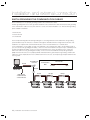
EARTH-GROUNDING THE COMMUNICATION CABLES
We recommend you to use a proper grounding system for the communication cables.
The best grounding method is to earth-ground the shield wire of the communication cable. However, the earth-grounding
of the communication cable is not easy at all, and it also causes an increased installation cost. There are three grounding
points available for installation:
1. Earth Ground
2. Chassis Ground
3. Power Ground
The most important thing about the earth-grounding lies in connecting neither end of the shield wire to the grounding
system simultaneously. This will cause a current flow through the shield wire when the voltage level of both ends of the
shield wire is not equal and this current flow will introduce some noise and interference to communications.
It is recommended to connect ONLY one end of the shield wire of the communication cable to the grounding system. If
you can locate an earth grounding point nearby, connect one end of the shield wire to that point. If you could hardly locate
an earth grounding point nearby, connect one end of the shield wire to the chassis ground point. If you could locate
neither of an earth or chassis grounding point nearby, connect one end of the shield wire to the power ground point
(GND). Note that if the chassis is not properly earthed and floated from the ground level, then grounding communication
cable to the chassis will produce the worst communication. If this is the case, use the power ground point rather than the
chassis ground.
RS-232
RS-422 Cable
RS-422/RS-232
Converter
Communication
Wires
Connect
ShieldWire
Open
RS-422
HOST PC
RS-422
RS-422
RS-422
Earth Ground
or Chasis Ground
or Power Ground
GND
GND
#1
14_ installation and external connection
GND
#2
GND
#3
#n
POWER, READER, AND I/O CONNECTION
Power Connection
INSTALLATION AND EXTERNAL CONNECTION
DC +12V
GND
- Connect the plus (+) line of DC 12V to the corresponding port (+12V).
- Connect the GND (-) line of DC 12V to the GND (-) port.
Reader Connection
Reader #4
Reader #1
Reader #3
Reader #2
GND
D1
D0
DC+12V
- Connect the plus (+) line of the reader to the corresponding port (DC +12V).
- Connect the minus (-) line of the reader to the GND (-) port.
- Connect the data 0 line of the reader to its port data 0 (D0).
- Connect the data 1 line of the reader to its port data 1 (D1).
Two Door Control
Three Door Control
Four Door Control
Door Number
External Reader
Internal Reader
Exit Button
1
2
1
2
3
1
2
3
4
Reader #1
Reader #3
Reader #1
Reader #3
Reader #4
Reader #1
Reader #2
Reader #3
Reader #4
Reader #2
Reader #4
Reader #2
None
None
None
None
None
None
None
None
None
Internal Exit Button
Internal Exit Button
Internal Exit Button
Internal Exit Button
Internal Exit Button
Internal Exit Button
• Refer to the list of compatible readers.
- SSA-P400(T) : 26Bit Wiegand Reader
- SSA-P401(T) : 34Bit Wiegand Reader
English15
installation and external connection
Input Connection
GND
Input #7
GND
Input #6
GND
Input #5
GND
Input #4
GND
Input #3
GND
Input #2
GND
Input #1
Door Open Sensor
PUSH
Exit Button
Door Open Sensor
PUSH
Exit Button
- Exit Button Connection (Input #1, Input #3)
1. Connect one line of the Exit button to an input port (Door 1: Input #1, Door 2: Input #3) of the Exit button.
2. Connect the other line of the Exit button to GND (-).
- Door Sensor Connection (Input #2, Input #4)
1. Connect one line (COM) of the door open/close sensor to the input port (Door 1: Input #2, Door 2: Input #4) of
the door sensor.
2. Connect the other line (NC) of the door sensor to GND (-).
Two Door Control
Three Door Control
Four Door Control
Door Number
Exit Button
Door Open Sensor
1
2
1
2
3
1
2
3
4
Input #1
Input #3
Input #1
Input #8
Input #10
Input #1
Input #3
Input #8
Input #10
Input #2
Input #4
Input #2
Input #9
Input #11
Input #2
Input #4
Input #9
Input #11
16_ installation and external connection
Note
I/O Board
I/O Board
I/O Board
I/O Board
Output Connection
DC +12V
GND
INSTALLATION AND EXTERNAL CONNECTION
Door Lock
NC
COM
POWER FAIL SAFE
COM
NO
Alarm Device
GND
POWER FAIL SECURE
- If the door lock is in POWER FAIL SAFE mode: (Door 1: Relay #1, Door 2: Relay #3)
1. Connect the COM line of the Door Lock relay to DC +12V.
2. Connect the plus (+) line of the Door Lock to the Normal Close (NC) line of the Door Lock relay.
3. Connect the minus (-) line of the Door Lock to GND (-).
- If the Door Lock is in POWER FAIL SECURE mode: (Door 1: Relay #1, Door 2: Relay #3)
1. Connect the COM line of the relay to DC +12V.
2. Connect the plus (+) line of the Door Lock to the Normal Open (NO) line of the Door Lock relay.
3. Connect the minus (-) line of the Door Lock to GND (-).
Alarm Device Connection (Door 1 Alarm: Relay #2, Door 2 Alarm: Relay #4)
1. Connect the COM line of the alarm device relay to DC +12V.
2. Connect the plus (+) line of the alarm device to the NO line of the alarm device relay.
3. Connect the minus (-) line of the alarm device to GND (-).
Two Door Control
Three Door Control
Four Door Control
Door Number
Door Lock
Alarm Device
1
2
1
2
3
1
2
3
4
Relay Output #1
Relay Output #3
Relay Output #1
Relay Output #8
Relay Output #10
Relay Output #1
Relay Output #3
Relay Output #8
Relay Output #10
Relay Output #2
Relay Output #4
Relay Output #2
Relay Output #9
Relay Output #11
Relay Output #2
Relay Output #4
Relay Output #9
Relay Output #11
Note
I/O Board
I/O Board
I/O Board
I/O Board
English17
installation and external connection
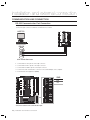
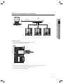
COMMUNICATION LINE CONNECTION
RS-232 Communication Port Connection
A 9-pin connector for serial communication is required to make connection to the PC.
Connect the 9 pin connector for RS-232 communications as follows:
HOST PC
RS-232
2
3
5
9-Pin Female Connector
1. Connect RS-232 TX to pin #2 of the 9-pin connector.
2. Connect RS-232 RX to pin #3 of the 9-pin connector.
3. Connect RS-232 GND to pin #5 of the 9-pin connector.
4. Connect the serial communication connector to the serial COM port of the computer.
5. Install and launch the application (SAMS).
GND
RX
TX
- Check the location of the communication port.
18_ installation and external connection
RS-422 Communication Port Connection (Standalone)
The RS-422/RS-232 converter is required to establish RS-422 communications. Connect the 9-pin connector of
the RS-422/RS-232 converter as follows:
INSTALLATION AND EXTERNAL CONNECTION
RS-422/232
Converter
RxD
TxD
Power
RS-232C
HOST
T+ T- R+ R-
MAX. 1200m
TXTX+
RXRX+
1. Connect RS-422 TX(-) to the RX(-) port of the converter.
2. Connect RS-422 TX(+) to the RX(+) port of the converter.
3. Connect RS-422 RX(-) to the TX(-) port of the converter.
4. Connect RS-422 RX(+) to the TX(+) port of the converter.
5. Connect the 9-pin connector of the RS-422/RS-232 converter to the serial COM port of the computer.
6. Install and launch the application (SAMS).
RX+
RXTX+
TX-
- Check the location of the communication port.
English19
installation and external connection
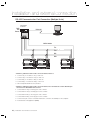
RS-422 Communication Port Connection (Multiple Units)
The RS-422/RS-232 converter is required to establish RS-422 communications.
RS-422/232
Converter
RxD
TxD
Power
RS-232C
HOST
T+ T- R+ R-
MAX. 1200m
TXTX+
RXRX+
- Follow the guidelines below to make connection between devices.
1. Connect TX(-) of one device to TX(-) of other one.
2. Connect TX(+) of one device to TX(+) of other one.
3. Connect RX(-) of one device to RX(-) of other one.
4. Connect RX(+) of one device to RX(+) of other one
5. Set a unique board ID for each product.
- Follow the guidelines below to make connection between the terminal device and the RS-422 9-pin
connector of the RS-422/RS-232 converter.
1. Connect RS-422 TX(-) to the RX(-) port of the converter.
2. Connect RS-422 TX(+) to the RX(+) port of the converter.
3. Connect RS-422 RX(-) to the TX(-) port of the converter.
4. Connect RS-422 RX(+) to the TX(+) port of the converter.
5. Connect the 9-pin connector of the RS-422/RS-232 converter to the COM port of the computer.
6. Install and launch the application (SAMS).
20_ installation and external connection
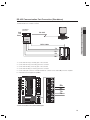
TCP/IP Communication Port Connection
1) TCP/IP Communication Configuration
HUB
PC
INSTALLATION AND EXTERNAL CONNECTION
TCP / IP
TCP / IP
2) TCP/IP Connection
Connect the LAN cable to the TCP/IP RJ-45 jack as shown.
(applicable only to SSA-P400T / SSA-P401T)
1. Connect the RJ45 jack of the unit to the RJ45 plug, the LAN cable of the network system.
2. Set a unique communication address (COMM ADDR) for each unit
3. Install and launch the application (SAMS).
English21
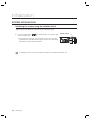
initialization
SYSTEM INITIALIZATION
Initializing the system using the Initialize switch
Apply the power and initialize the system by using the initialization switch.
1. Locate the Initialize switch (
switches simultaneously.
) on the upper right corner and press both
Initialize Switch
• Pressing both of the switches at the same time for about 2 seconds will
sound initialization ready beep. Releasing both switches will stop the beep,
and restarts the system after the initialization.
J
Initializing the system restores all your settings to the default, consequently all ID data will be lost.
22_ initialization
BOARD ID SETTING
0/
Each device in the multi-serial communication connection is assigned a unique number to identify
each other.
1. The initial value of the switch is “0”, and all of the 8 switches are defaulted to OFF.
,4%)
• You can specify between 0 and 255 for the board ID.
❖ Refer to the example below for the board ID.
Example 1
1+2 = 3 (Board ID = 3)
M
Example 2
Example 3
4+32 = 36 (Board ID = 36)
1+2+4+8+16+32+64+128
= 255 (Board ID = 255 )
The board ID is the unique address of the device so it should not be duplicated.
English23
INITIALIZATION
2. Each switch has a unique value, and the board ID is the sum of the values of the switches.
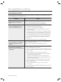
troubleshooting
TROUBLESHOOTING
If the product does not work properly, please check the followings before contacting us. If the trouble persists, please
contact the SAMSUNG Customer Service near you.
Problem
Action
Can I specify RF only or RF+P/W
mode differently according to the
card?
1)
2)
It is not available.
The mode is defined for each reader device, not the card.
Thus, you can not specify the mode for each card differently.
Ever since I mass-transferred data
using the PC application, some
cards are not allowed for access.
1)
You might have not saved card information to the PC, but just to the device
when registering card using the PC application.
Check if there is a registered, but disallowed card in the PC.
For an unregistered card, try to enter it again and save to the PC before
transferring to the device.
The Mass Transfer/Group Transfer function of the PC application will delete
all card data in the device before transferring the PC data to the device. As
such, if you usually register one card on a daily basis, you may not save it
to the PC but transfer to the device, which causes unsaved card numbers
not to be registered with the device in the operation of a mass-transfer.
If this is not the case, the problem may be caused by the defective of an
internal circuit.
Contact the nearest customer service for technical assistance.
2)
3)
4)
5)
The RF card works normally, but
the key input (for the card number)
using the keypad does not work
properly.
Use the provided software program to check the use of the keypad while the
reader is operating in a certain mode.
Enable the use of the keypad before downloading data to the device.
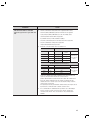
The reader reads a card normally
but no reaction is made by the
device or an irrelevant card number
is displayed.
1)
2)
3)
4)
5)
24_ troubleshooting
Check the power source of the reader. (Check if the LED indicator of the
reader is blinking when it has read a card.)
Check if the reader works properly. (Disconnect the reader from the system
and use a measuring device such as an oscilloscope to measure the output
port of the reader.)
Check if the reader is properly connected to the system (device).
- Check if the Wiegand communication lines between the reader and the
system are properly established. (D0, D1)
- The Wiegand communication line should be connected to GND. (A
different power source may be fine but the earth-grounding point should
be connected to GND of the device.)
If you find the output signal from the device but with severe noise when
using a measuring device to measure the Wiegand communication line,
please check the followings:
- Connect the shield wire and the spare wire of the cable to GND.
- Use the repeater.
If the problem persists after performing all the checkpoints above, contact the customer
service for technical help.
Problem
No communication is available
when the system is in sync with the
PC.
Action
1)
Check the communication settings between the PC application and the device.
- Check the board ID (COMM address) and match it with that of the PC application.
- Specify a unique board ID (COMM address) for each of the multiple devices.
- Check the baud rate if it matches with the PC application.
- If you initialize the device, it will be defaulted to 9,600bps.
- Check if the communication port of the PC matches that of the PC application.
- Check the communication settings of the PC application.
2)
Parity Bit : NONE, Data Bit: 8bit, Stop Bit: 1bit
Check the connection status of RS-232 and RS-422.
RS-232
RS-422 (Independent Communication)
SSA-P400
PC
SSA-P400
RS-232/RS-422
Converter
TX Port
RX
RX(-)
TX(-)
RX Port
TX
RX(+)
TX(+)
GND
GND
TX(-)
RX(-)
TX(+)
RX(+)
PC
Connected to the
RS-232 cable of the
converter
Rs-422 (Multi-Unit Communication)
SSA-P400
SSA-P400
RS-232/RS-422
RX(-)
RX(-)
TX(-)
RX(+)
RX(+)
TX(+)
TX(-)
TX(-)
RX(-)
TX(+)
TX(+)
RX(+)
PC
Connected to the
RS-232 cable of the
converter
For RS-422 communications, install a termination resistor at the point where the
system is connected to the RS-422/RS-232 converter of the PC.
(Install a 120Ω termination resistor between the RX+ and the RX- terminals on the
device side, another 120Ω between the TX+ and the TX- terminals; the same
should be done to the converter. If you are not sure about the wiring, contact the
customer service for your help.)
If the problem persists after you followed the instructions above, this may be caused
by the defective of an internal circuit. Contact the customer service.
¼ If no communication is established after you tried to do so with multiple
devices, pick just one device and connect it to the RS-232/RS-422
converter, and to the PC. Then, check if there is any communication
available.
English 25
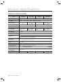
product specifications
PRODUCT SPECIFICATIONS
Item
SSA-P400
SSA-P400T
SSA-P401
Users
1,000 ~ 20,000 / 30,000 / 40,000 / 50,000 Users (Default :20,000)
Event Buffer
20,000 ~ 29,500 / 3,000 / 8,000 / 14,000 (Default : 29,500)
DC 12V, MAX.
380mA
Power / Current
DC 12V,
MAX.430mA
Reader Port
4ea: 26bit Wiegand, 4 / 8bit Burst for PIN
Door Open Time
00~99 Sec. (Default 3Sec.)
Communication
RS232 / RS422 /
RS485
Baud Rate(bps)
9,600bps
Input Port
15ea
RS232 / RS422 /
RS485, TCP/IP
DC 12V, MAX.
380mA
SSA-P401T
DC 12V,
MAX.430mA
4ea: 34bit Wiegand, 4 / 8bit Burst for PIN
RS232 / RS422 /
RS485
RS232 / RS422 /
RS485, TCP/IP
12ea : 2 FORM-C Relay Output (COM, NO, NC) / DC12V~18V, Rating Max.2A
Output Port
3ea: TTL Output / DC5V, Rating Max.20mA
LED Indicator
38ea : 21 LED Indicators (Red, Green and Yellow)
17 LED Indicators (Red, Yellow)
Beeper
Piezo Buzzer
Operating Temperature
0°C to +50°C
Operating Humidity
10% to 90% relative humidity non-condensing
Color / Material
Black/ PCB
Dimension
(W x H x D(mm))
145 x 185 x 18
Weight
340g
26_ product specifications
350g
340g
350g
Correct Disposal of This Product (Waste Electrical & Electronic Equipment)
(Applicable in the European Union and other European countries with separate collection systems)
This marking on the product, accessories or literature indicates that the product and its electronic accessories (e.g.
charger, headset, USB cable) should not be disposed of with other household waste at the end of their working life. To
prevent possible harm to the environment or human health from uncontrolled waste disposal, please separate these
items from other types of waste and recycle them responsibly to promote the sustainable reuse of material resources.
Household users should contact either the retailer where they purchased this product, or their local government office, for
details of where and how they can take these items for environmentally safe recycling.
Business users should contact their supplier and check the terms and conditions of the purchase contract.
This product and its electronic accessories should not be mixed with other commercial wastes for disposal.
Correct disposal of batteries in this product
(Applicable in the European Union and other European countries with separate battery return systems.)
This marking on the battery, manual or packaging indicates that the batteries in this product should not be disposed of
with other household waste at the end of their working life. Where marked, the chemical symbols Hg, Cd or Pb indicate
that the battery contains mercury, cadmium or lead above the reference levels in EC Directive 2006/66. If batteries are
not properly disposed of, these substances can cause harm to human health or the environment.
To protect natural resources and to promote material reuse, please separate batteries from other types of waste and
recycle them through your local, free battery return system.
AB82-02555A