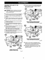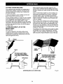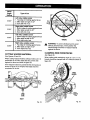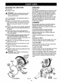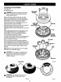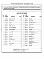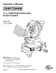
1
Operator's Manual
10 in. COMPOUND
MITER SAW
Double Insulated
Model No.
315.212500
Save this manual
future reference.
for
• Safety
• Features
• Adjustments
• Operation
• Maintenance
• Parts List
_, CAUTION:
Read and follow
all Safety Rules and Operating
Instructions
before first use of
this product.
Customer
Sears,
Help Line: 1-800-932-3188
Roebuck
Visit the Craftsman
983000-027
3-02
and Co.,
web
3333
page:
Beverly
Rd.,
Hoffman
www.sears.com/craftsman
Estates,
IL 60179
USA
_ _
_lllg
I1._
•
Table of Contents .................................................................................................................................................
2
•
Warranty and Introduction
2
•
Rules for Safe Operation .................................................................................................................................
•
Glossary of Terms ................................................................................................................................................
6
•
Product Specifications
7
•
Accessory List ......................................................................................................................................................
8
•
Loose arts List and Tools Needed .......................................................................................................................
9
•
Labels .................................................................................................................................................................
•
Features .......................................................................................................................................................
11-13
•
Adjustments
.................................................................................................................................................
14-20
•
Operation
.....................................................................................................................................................
21-27
•
Laser Guide .................................................................................................................................................
28-29
•
Maintenance
................................................................................................................................................
30-31
•
Accessories ..................................................................................................................................................
31-33
•
Exploded Views and Repair Parts Lists .......................................................................................................
34-41
•
Parts Ordering / Service ....................................................................................................................................
...................................................................................................................................
3-6
and Unpacking ................................................................................................................
10
42
FULL ONE YEAR WARRANTY
If this product fails due to a defect in material or workmanship within one year from the date of purchase,
Sears will repair it free of charge.
Contact a Sears Service Center for repair.
If this product is used for commercial
or rental purposes, this warranty applies only for 90 days from the date
of purchase.
This warranty gives you specific legal rights, and you may also have other rights which vary from state to state.
Sears, Roebuck and Co., Dept. 817WA, Hoffman Estates, IL 60179
Your saw has many features for making cutting
operations more pleasant and enjoyable. Safety,
performance and dependability have been given top
priority in the design of this saw making it easy to
maintain and operate.
_i,
CAUTION: Carefully read through this entire
operator's manual before using your new saw.
Pay close attention to the Rules For Safe
Operation, and all Safety Alert Symbols including
Danger, Warning and Caution. If you use your
saw properly and only for what it is intended, you
will enjoy years of safe, reliable service.
Look for this symbol to point out important
means attention!!!
Your safety is involved.
safety
precautions.
It
WARNING:
The operation of any tool can result in foreign objects being thrown into your eyes, which
can result in severe eye damage. Before beginning power tool operation, always wear
safety goggles or safety glasses with side shields and a full face shield when needed. We
recommend Wide Vision Safety Mask for use over eyeglasses or standard safety glasses
with side shields. Always wear eye protection which is marked to comply with ANSI Z87.1.
2
The purpose of safety symbols is to attract your attention to possible dangers. The safety symbols, and the
explanations with them, deserve your careful attention and understanding. The safety warnings do not by
themselves eliminate any danger. The instructions or warnings they give are not substitutes for proper accident
prevention measures.
SYMBOL
A
MEANING
SAFETY
ALERT
SYMBOL:
Indicates danger, warning or caution. May be used in conjunction with other symbols or pictographs,
A
DANGER: Failure to obey a safety warning will result in serious injury to yourself or to others.
Always follow the safety precautions to reduce the risk of fire, electric shock and personal injury.
A
WARNING:
Failure to obey a safety warning can result in serious injury to yourself or to others.
Always follow the safety precautions to reduce the risk of fire, electric shock and personal injury.
A
CAUTION: Failure to obey a safety warning may result in property damage or personal injury to
yourself or to others. Always follow the safety precautions to reduce the risk of fire, electric shock
and personal injury.
NOTE:
Advises you of information or instructions vital to the operation or maintenance of the equipment.
DOUBLE INSULATION
IMPORTANT
Double insulation is a concept in safety, in electric
power tools, which eliminates the need for the usual
three-wire grounded power cord. All exposed metal
parts are isolated from internal metal motor
components with protecting insulation. Double
insulated tools do not need to be grounded.
Servicing requires extreme care and knowledge of the
system and should be performed only by a qualified
service technician. For service we suggest you return
the tool to your nearest Sears store for repair. Always
use original factory replacement parts when servicing.
A
•
KEEP THE WORK AREA CLEAN. Cluttered work
areas and work benches invite accidents. DO NOT
leave tools or pieces of wood on the saw while it is
in operation.
•
DO NOT USE IN DANGEROUS
WARNING:
Do not attempt to operate this tool
until you have read thoroughly and understand
completely all instructions, safety rules, etc.
contained in this manual. Failure to comply can
result in accidents involving fire, electric shock,
or serious personal injury. Save operator's
manual and review frequently for continuing safe
operation, and instructing others who may use
this tool.
MENTS. Do not use power tools near gasoline or
other flammable liquids, in damp or wet locations,
or expose them to rain. Keep the work area well lit.
•
READ ALL INSTRUCTIONS
•
KNOW YOUR POWER TOOL. Read the operator's
manual carefully. Learn the saw's applications and
limitations as well as the specific potential hazards
related to this tool.
•
GUARD AGAINST ELECTRICAL SHOCK by
preventing body contact with grounded surfaces
such as pipes, radiators, ranges, refrigerator
enclosures.
•
KEEP GUARDS IN PLACE and in good working
order.
•
REMOVE WRENCHES AND ADJUSTING KEYS.
Get in the habit of checking - before turning on tool
- that hex keys and adjusting wrenches are removed from tool.
ENVIRON-
KEEP CHILDREN AND VISITORS AWAY. All
visitors should wear safety glasses and be kept a
safe distance from work area. Do not let visitors
contact tool or extension cord while operating.
MAKE WORKSHOP CHILDPROOF with padlocks
and master switches or by removing starter keys.
DO NOT FORCE THE TOOL it will do the job
better and more safely at the rate for which it was
designed.
USE THE RIGHT TOOL FOR THE JOB. Do not
force the tool or attachment to do a job it was not
designed for. Use it only the way it was intended.
•
breakage of parts, saw stability, mounting and any
other conditions that may affect its operation. A
damaged part must be properly repaired or replaced by a qualified service technician at a Sears
store or repair center to avoid risk of personal
injury.
USE THE PROPER EXTENSION CORD. Make
sure your extension cord is in good condition. Use
only a cord heavy enough to carry the current your
product will draw. An undersized cord will cause a
drop in line voltage resulting in loss of power and
overheating. A wire gage size (A.W.G.) of at least
14 is recommended for an extension cord 25 feet
NEVER LEAVE TOOL RUNNING UNATTENDED.
TURN THE POWER OFF. Do not leave tool until it
or less in length. If in doubt, use the next heavier
gage. The smaller the gage number, the heavier
the cord.
•
comes to a complete stop.
FIRMLY CLAMP OR BOLT your miter saw to a
workbench or table at approximately hip height.
INSPECT TOOL CORDS AND EXTENSION
CORDS PERIODICALLY and, if damaged, have
repaired by a qualified service technician at a
Sears store or repair center. Stay constantly aware
of cord location and keep it well away from the
moving blade.
•
DRESS PROPERLY. Do not wear loose clothing,
gloves, neckties, rings, bracelets, or other jewelry
that can get caught and draw you into moving
parts. Nonslip footwear is recommended. Also
wear protective hair covering to contain long hair.
•
ALWAYS WEAR SAFETY GLASSES WITH SIDE
SHIELDS. Everyday eyeglasses have only impactresistant lenses, they are NOT safety glasses.
•
WEAR A DUST MASK to keep from inhaling fine
particles.
•
PROTECT YOUR HEARING. Wear hearing
protection during extended periods of operation.
•
SECURE WORK. Use clamps or a vise to hold
work when practical. It's safer than using your
hand and frees both hands to operate tool.
•
DO NOT OVERREACH.
balance at all times.
•
MAINTAIN TOOLS WITH CARE. Keep tools sharp
and clean for better and safer performance. Follow
instructions for lubricating and changing accessories.
•
DISCONNECT ALL TOOLS. When not in use,
before servicing, or when changing attachments,
all tools should be disconnected.
•
AVOID ACCIDENTAL STARTING. Be sure switch
is off when plugging in any tool.
•
USE ONLY CORRECT BLADES. Use the right
blade size, style and cutting speed for the material
and the type of cut. Do not use blades with incorrect size holes. Never use blade washers or blade
bolts that are defective or incorrect. The maximum
blade capacity of your saw is 10 in.
•
KEEP BLADES CLEAN, SHARP, AND WITH
SUFFICIENT SET. Sharp blades minimize stalling
and kickback.
•
DO NOT REMOVE THE SAW'S BLADE
GUARDS. Never operate the saw with any guard or
cover removed. Make sure all guards are operating
properly before each use.
•
KEEP HANDS AWAY FROM CUTTING AREA. Do
not reach underneath work or in blade cutting path
with your hands and fingers for any reason. Always
turn the power off.
_1= WARNING:
•
Keep proper footing and
•
USE RECOMMENDED ACCESSORIES. Using
improper accessories may risk injury. Consult
operator's manual for recommended accessories.
•
NEVER STAND ON TOOL. Serious injury could
occur if the tool is tipped or if the blade is
unintentionally contacted.
•
CHECK DAMAGED PARTS. Before using the tool
again, check any damaged parts, including guards,
for proper operation and performance. Check
alignment of moving parts, binding of moving parts,
Blade coasts after being turned off.
DO NOT ABUSE CORD. Never-yank cord to
disconnect it from receptacle. Keep cord from heat,
oil, and sharp edges.
USE ONLY OUTDOOR EXTENSION CORDS. Use
only extension cords with the marking "Acceptable
for use with outdoor appliances; store cords indoors
while not in use". Use extension cords with an
electrical rating not less than the saw's rating.
Always disconnect the extension cord from the
outlet before disconnecting the product from the
extension cord.
•
DO NOT USE TOOL IF SWITCH DOES NOT
TURN IT ON AND OFF. Have defective switches
replaced by a qualified service technician at a
Sears store or repair center.
4
•
KEEP TOOL DRY, CLEAN, AND FREE FROM OIL
AND GREASE. Always use a clean cloth when
cleaning. Never use brake fluids, gasoline, petroleum-based products, or any solvents to clean tool.
•
ALWAYS SUPPORT LONG WORKPIECES while
cutting to minimize risk of blade pinching and
kickback. Saw may slip, walk or slide while cutting
long or heavy boards.
•
BEFORE MAKING A CUT, be sure all adjustments
are secure.
•
BE SURE BLADE PATH IS FREE OF NAILS.
Inspect for and remove all nails from lumber before
cutting.
•
ALWAYS USE A CLAMP to secure the workpiece
when possible.
•
NEVER TOUCH BLADE or other moving parts
during use for any reason.
•
BE SURE THE BLADE CLEARS THE WORKPIECE. Never start the saw with the blade touching
the workpiece. Allow motor to come up to full
speed before starting cut.
•
MAKE SURE THE MITER TABLE AND SAW
ARM (BEVEL FUNCTION) ARE LOCKED IN
POSITION BEFORE OPERATING YOUR SAW.
ALWAYS release the power switch and allow the
saw blade to stop rotating before raising it out of
the workpiece.
•
DO NOT TURN THE MOTOR SWITCH ON AND
OFF RAPIDLY. This could cause the saw blade to
loosen and could create a hazard. Should this ever
occur, stand clear and allow the saw blade to come
to a complete stop. Disconnect your saw from the
power supply and securely retighten the blade bolt.
•
USE ONLY SEARS REPLACEMENT PARTS. All
repairs, whether electrical or mechanical, should
be made by a qualified service technician at a
Sears store or repair center.
_1= WARNING: When servicing, use only identical
Craftsman replacement parts. Use of any other
parts may create a hazard or cause product
damage.
Lock the miter table by securely tightening the
miter lock handle. Lock the saw arm (bevel function) by securely tightening the bevel lock knob.
•
•
NEVER USE THIS TOOL IN AN EXPLOSIVE
ATMOSPHERE.
Normal sparking of the motor
could ignite fumes.
NEVER USE A LENGTH STOP ON THE FREE
SCRAP END OF A CLAMPED WORKPIECE.
POLARIZED PLUGS. To reduce the risk of electric
shock, this tool has a polarized plug (one blade is
wider than the other). This plug will fit in a polarized outlet only one way. If the plug does not fit
fully in the outlet, reverse the plug. If it still does
not fit, contact a qualified electrician to install the
proper outlet. Do not change the plug in any way.
NEVER hold onto or bind the free scrap end of the
workpiece in any operation. If a work clamp and
length stop are used together, they must both be
installed on the same side of the saw table to
prevent the saw from catching the loose end and
kicking up.
•
NEVER cut more than one piece at a time. DO
NOT STACK more than one workpiece on the saw
table at a time.
•
NEVER PERFORM ANY OPERATION
HAND. Always place the workpiece to be cut on
the miter table and position it firmly against the
fence as a backstop. Always use the fence,
IF ANY PART OF THIS MITER SAW IS MISSING
or should break, bend, or fail in any way, or should
any electrical component fail to perform properly,
shut off the power switch, remove the miter saw
plug from the power source and have damaged,
missing, or failed parts replaced before resuming
operation.
•
NEVER hand hold a workpiece that is too small to
be clamped. Keep hands clear of the no hands
zone.
DO NOT OPERATE THIS TOOL WHILE UNDER
THE INFLUENCE OF DRUGS, ALCOHOL, OR
ANY MEDICATION.
•
NEVER reach behind, under, or within three inches
of the blade and its cutting path with your hands
and fingers for any reason.
•
NEVER reach to pick up a workpiece, a piece of
scrap, or anything else that is in or near the cutting
path of the blade.
•
AVOID AWKWARD OPERATIONS AND HAND
POSITIONS where a sudden slip could cause your
hand to move into the blade. ALWAYS make sure
you have good balance. NEVER operate your
miter saw on the floor or in a crouched position.
•
FREE-
•
ALWAYS STAY ALERT! Do not allow familiarity
(gained from frequent use of your saw) to cause a
careless mistake. ALWAYS RE•EMBER that a
careless fraction of a second is sufficient to inflict
severe injury.
•
STAY ALERT AND EXERCISE CONTROL. Watch
what you are doing and use common sense. Do
not operate tool when you are tired. Do not
rush.
MAKE SURE THE WORK AREA HAS AMPLE
LIGHTING to see the work and that no obstructions will interfere with safe operation BEFORE
performing any work using your saw.
NEVER stand or have any part of your body in line
with the path of the saw blade.
5
•
ALWAYS TURN OFF THE SAW before disconnecting it to avoid accidental starting when reconnecting to power supply. NEVER leave the saw
unattended while connected to a power source.
•
NEVER lift this tool by gripping the sliding miter
fence.
•
AVOID direct eye exposure when using the laser
guide.
•
SAVE THESE INSTRUCTIONS.
,_
WARNING:
Some dust created by power
sanding, sawing, grinding, drilling, and other
construction activities contains chemicals known
to cause cancer, birth defects or other reproductive harm. Some examples of these chemicals
are:
• lead from lead-based paints,
• crystalline silica from bricks and cement
and other masonry products, and
Refer to them
• arsenic and chromium from chemicallytreated lumber.
frequently and use to instruct other users. If you
loan someone this tool, loan them these instructions also.
Your risk from these exposures varies, depending
on how often you do this type of work. To reduce
your exposure to these chemicals, work in a well
ventilated area and work with approved safety
equipment, such as those dust masks that are
specially designed to filter out microscopic
particles.
SAVETHESEINSTRUCTIONS
Arbor
Set
The shaft on which a blade or cutting tool is mounted.
The distance that the tip of the sawblade tooth is bent
(or set) outward from the face of the blade.
Bevel Cut
A cutting operation made with the blade at any angle
other than 90 ° to the miter table,
Crosscut
A cutting or shaping operation made across the grain
of the workpiece.
Compound Miter Cut
A compound miter cut is a cut made using a miter
angle and a bevel angle at the same time.
Freehand
Performing a cut without using a fence, miter gage,
fixture, work clamp, or other proper device to keep the
workpiece from twisting or moving during the cut.
Gum
A sticky, sap based residue from wood products.
Miter Cut
A cutting operation made with the blade at any angle
other than 90" to the fence.
Resin
A sticky, sap base substance that has hardened.
Revolutions Per Minute (RPM)
The number of turns completed by a spinning object
in one minute.
Saw Blade Path
The area over, under, behind, or in front of the blade.
As it applies to the workpiece, that area which will be,
or has been, cut by the blade.
Throw-Back
Throwing of a workpiece in a manner similar to a
kickback. Usually associated with a cause other than
the kerf closing, such as a workpiece not being
against the fence, being dropped into the blade, or
being placed inadvertently in contact with the blade.
Through Sawing
Any cutting operation where the blade extends
completely through the thickness of the workpiece.
Workpiece
The item on which the cutting operation is being done.
The surfaces of a workpiece are commonly referred to
as faces, ends, and edges.
Zero Clearance
Throat Plate
A plastic throat plate inserted in the miter table that
allows for blade clearance. When you make your first
cut with your compound miter saw, the saw blade cuts
a slot through the throat plate the exact width of the
blade. This provides for a zero clearance kerr that
minimizes workpiece tear-out.
No Hands Zone
The area between the marked lines on the left and
right side of the miter table base. This zone is
identified by no hands zone labels placed inside the
marked lines on the miter table base.
Blade Diameter
Blade Arbor
No Load Speed
Rating
Input
Cutting Capacity with Miter at 0°/Bevel 0°:
10 in.
5/8 in.
5-7/16 in. wide x 2-9/16 in. thick
3-1/2 in. thick x 4 in. wide
5000 RPM
Maximum Cutting Capacity with Miter at 45°/Bevel 0°:
15 Amperes
3-7/8 in. wide x 2-9/16 in. thick
120 Volts, 60 Hz, AC Only
Net Weight
32 Ibs.
Maximum Cutting Capacity with Miter at 0°/Bevel 45°:
5-7/16 in. wide x 1-9/16 in. thick
Maximum Cutting Capacity with Miter at 45°/Bevel 45°:
3-7/8 in. wide x 1-1/2 in. thick
Your Compound Miter Saw has been shipped
completely assembled except for the blade, miter lock
handle, laser, and dust guide.
Do not discard the packing materials until you
have carefully inspected the saw, identified all
loose parts, and satisfactorily operated your new
saw.
,_
WARNING:
If any parts are missing, do not
operate this tool until the missing parts are
replaced. Failure to do so could result in possible
serious personal injury.
•
Remove all loose parts from the carton. Separate
and check with the list of loose parts. See Figure 2.
•
Remove the packing materials from around your
saw.
•
Carefully lift saw from the carton and place it on a
level work surface. This saw is heavy. To avoid
back injury, get help when needed.
Your saw has been shipped with the saw arm
secured in the down position. To release the saw
arm, push down on top of saw arm and cut the
tie-wrap.
•
Lift the saw arm by the handle. Hand pressure
should remain on the saw arm to prevent sudden
rise upon release of the tie wrap.
•
Examine all parts to make sure no breakage or
damage has occurred during shipping.
If any parts are damaged or missing, do not attempt to
plug in the power cord and turn the switch on until the
damaged or missing parts are obtained and are
installed correctly.
7
Thefollowingaccessories
areincludedwith your
Compound Miter Saw:
•
Dust Bag
•
Table Clamp Bracket
•
Table Extensions (1)
•
Extension Clamp Bracket
•
Support Rod (2)
•
Square Head Bolt (1)
•
Stop Block
•
Clamp Bracket Screw (1)
•
Stop Block Knob
•
Carriage Bolt (1)
•
Wing Nut
•
Adjustment Screw (4)
•
Work Clamp Assembly
STOP
BLOCK
KNOB
DUSTBAG
STOPBLOCK
/
TABLE
EXTENSION
/
CARRIAGE-_L.._J._,_ _
WORKCLAMP
ASSEMBLY
BOLT_
L,,.'_,_
_
ADJUSTMENT
s PPORT
ROD _
_
ADJUSTMENT
SCREW
/TABLE
WING
NUT
EXTENSION
CLAMP
BRACKET
CLAMP
BRACKET
CLAMP
BRACKET
SCREW
The following items are included with your Compound Miter Saw:
•
Saw Blade - 10 in.
•
6 mm Hex Key Wrench
•
Miter Lock Handle
•
Dust Guide
•
•
8 mm Hex Key Wrench
Laser Guide
•
Blade Wrench
•
Hex Key Bolt
•
5 mm Hex Key Wrench
•
Operator's
Manual
8 mm HEXKEY
SAW BLADE
BLADEWRENCH
DUSTGUIDE
5 mm HEXKEY
6 mm HEX KEY
_LOCK
HANDLE
Fig. 1
_I,
WARNING:
The use of attachments or accessories not listed might be hazardous and could cause
serious personal injury.
The following tools (not included) are needed for
checking adjustments of your saw or for installing the
blade:
FRAMINGSQUARE
COMBINATION
SQUARE
PHILLIPSSCREWDRIVER
The following labels are on the miter saw with locations indicated.
__/
I AWARNING:I
FAILURE TO RESTORE
ANDTIGHTEN
LOWER GUARD
SCREW MAY RESULT
IN A SERIOUS
INJURY
DANGER:DONOTREMOVE
ANY GUARD. USE OF SAW
WITHOUTTHIS GUARD WILL
RESULT N SEROUS
NJURY.
,A WARNING/ ADVERTENCIA
• For your safety, read owners manual before operating
miter saw.
• Wear eye protection.
• Keep hands out of path of saw blade.
• Do not operate saw without guards in place.
• Do not perform any operation freehand.
• Never reach around the saw blade.
• Turn off tool and wait for saw blade to stop before
moving workpiece or changing settings.
• Disconnect the saw from the power source before
changing blade or servicing,
• Do not expose to rain or use in damp places,
• Para su seguridad, lea el manual del usuario antes
de usar la sierra ingletadora.
10 inch Compound
Miter Saw
DOUBLEINSULATED5,000 RPM 120 VOLTSBOHz ACONLY15 A
I _kWARNING I WHEN SERVICING,USEONLY IDENTICAL
CRAFTSMANREPLACEMENTPARTS,
MODEL 315.212500
MADE ,NTAIWAN
SEARS,
ROEBUCK
• Customer
AND CO.
SER.NO.
r
C(_
-L
US
43F1
STATIONARyTOOt.
Help Line 1-800-932-3188
Fig. 2
10
KNOW
YOUR
COMPOUND
MITER
CUTTING CAPACITIES
SAW
See Figure 3.
When the miter angle (miter table) is set at 0 ° and
the bevel angle Is set at O°:
Before attempting to use your saw, familiarize yourself
with all operating features and safety requirements,
_i,
Your saw will cut materials up to a maximum of
5-7/16 in. wide x 2-9/16 in. thick,
WARNING:
Do not allow familiarity with your
saw to make you careless. Remember that a
careless fraction of a second is sufficient to inflict
severe injury.
It will cut materials up to a maximum thickness of
3-1/2 in. thick x 4 in. wide.
When the miter angle (miter table) is set at 45 ° and
the bevel angle is set at O°:
15 AMP MOTOR
Your saw will cut materials up to a maximum of
3-7/8 in. wide x 2-9/16 in. thick.
Your saw has a powerful t 5 amp motor with sufficient
power to handle tough cutting jobs. It is made with all
ball bearings, and has externally accessible brushes
for ease of servicing.
When the miter angle (miter table) is set at 0 ° and
the bevel angle is set at 45°:
Your saw wil! cut materials up to a maximum of
5-7/16 in. wide x 1-9/16 in. thick.
10 in. BLADE
When the miter angle (miter table) is set at 45 ° and
the bevel angle is set at 45°:
A 10 in. saw blade is included with your compound
miter saw. It wilt cut materials up to 2-9/16 in, thick or
5-7/16 in. wide, depending upon the angle at which
the cut is being made.
Your saw will cut materials up to a maximum of
3-7/8 in, wide x 1-1/2 in. thick,
6 mm
HEXKEY
SAW ARM
UPPER
BLADEGUARD
BEVEL
LOCKKNOB
BEVEL
SCALE
HEXKEY
STORAGEAREA
DUST
GUIDE
"NO HANDSZONE"
BOUNDARYLINE
NO HANDS
ZONE LABEL
FENCE
ZERO CLEARANCE
THROATPLATE
MITER
LOCKPLATE
MITER
SCALE
MITER
TABLE FRAME
MITER
CONTROLARM
POSITIVESTOP(S)
Fig. 3
11
CARRYING
SPINDLE
HANDLE
LOCK
BUTTON
See Figure 4.
See Figure 5.
For convenience when carrying or transporting your
miter saw from one place to another, a carrying
handle has been provided on top of the saw arm as
shown in figure 4. To transport, turn off and unplug
your saw, then lower the saw arm and lock it in the
down position. Lock saw arm by depressing the lock
pin.
A spindle lock button has been provided for locking
the spindle which keeps the blade in your saw from
rotating, Depress and hold the lock button while
installing, changing, or removing blade only.
SWITCH
CARRYING
HANDLE
SAW
ARM
SPINDLE
LOCK
LOCK
PIN
Fig. 5
TRIGGER
LOCK
See Figure 6.
To prevent unauthorized use of your compound miter
saw, we suggest that you disconnect it from the power
supply and lock the switch in the off position. To lock
the switch, install a padlock through the hole in the
switch trigger. A lock with a long shackle up to 13/64
in. diameter may be used. When the lock is installed
and locked, the switch is inoperable. Store the padlock key in another location.
MITERLOCK
HANDLE
SAW ARM
LOCKEDIN DOWNPOSITION
Fig. 4
MITER
LOCK
HANDLE
See Figure 4.
SWITCH
TRIGGER
The miter lock handle securely locks your saw at
desired miter angles.
PADLOCK
Fig. 6
12
POSITIVE
STOPS
ON MITER TABLE
24"
31_t'
Positive stops have been provided at O', 22-1/2" and
45 °. The 22-1/2 ° and 45" positive stops have been
provided on both the left and right side of the miter
table.
173/16"
31_
I
BEVEL LOCK KNOB
The bevel lock knob securely locks your compound
miter saw at desired bevel angles. Positive stop
adjustment screws have been provided on each side
of the saw arm. These adjustment screws are for
making fine adjustments at 0 ° and 45 °. See pages 17
and 18.
ELECTRIC
i
BRAKE
173/16"
24"
An electric brake has been provided to quickly stop
blade rotation after the switch is released.
Fig. 7
MITER FENCE
_,
The miter fence on your compound miter saw has
been provided to hold your workpiece securely
against when making all cuts; the left side is also
larger providing additional support. It has a sliding
feature for clearance of the saw arm when making
bevel or compound cuts.
ELECTRICAL
LOWER BLADE
The lower blade guard is made of shock-resistant,
see-through plastic that provides protection from each
side of the blade. It retracts over the upper blade
guard as the saw is lowered into the workpiece.
MOUNTING
CONNECTION
Your saw has a precision built electric motor. It should
be connected to a power supply that is 120 volts,
60 Hz, AC only (normal household current). Do not
operate this tool on direct current (DC). A substantial
voltage drop will cause a loss of power and the motor
will overheat. If your tool does not operate when
plugged into an outlet, double-check the power
supply.
Loosen the fence screw before attempting to slide the
miter fence. Once the desired position of the miter
fence is determined, tighten the fence screw to secure
the sliding fence.
SELF-RETRACTING
GUARD
WARNING: Always make sure your compound
miter saw is securely mounted to a workbench or
an approved workstand. Failure to do so could
result in an accident resulting in possible serious
personal injury.
A
WARNING: The operation of any saw can
result in foreign objects being thrown into your
eyes, which can result in severe eye damage.
Before starting power tool operation, always
wear safety goggles or safety glasses with side
shields and a full face shield when needed. We
recommend wide vision safety mask for use over
eyeglasses or standard safety glasses with side
shields.
a,
WARNING:
Do not attempt to modify this tool or
create accessories not recommended for use
HOLES
See Figure 7.
Your compound miter saw should be permanently
mounted to a firm supporting surface such as a
workbench. Four bolt holes have been provided in the
saw base for this purpose. Each of the four mounting
holes should be bolted securely using 3/8 in. machine
bolts, lock washers, and hex nuts (not included). Bolts
should be of sufficient length to accommodate the
saw base, lock washers, hex nuts, and the thickness
of the workbench.
with this tool. Any such alteration or modification
is misuse and could result in a hazardous
condition leading to possible serious personal
injury.
Tighten all four bolts securely.
The hole pattern for an 18 in. x 24 in. workbench is
shown in Figure 7. Carefully check the workbench
after mounting to make sure that no movement can
occur during use. If any tipping, sliding, or walking is
noted, secure the workbench to the floor before
operating.
13
WARNING:
To prevent accidental starting that
could cause possible serious personal injury,
assemble all parts to your saw before connecting
it to power supply. Saw should never be
connected to power supply when you are
assembling parts, making adjustments, installing
or removing blades, or when not in use.
TO INSTALL
_
As mentioned previously your saw has been factory
assembled and adjusted. The miter lock handle, dust
guide, dust bag, and blade are the only parts that
have to be installed.
MITER
LOCK
BLADE
See Figures 10, 11, and 12.
HANDLE
See Figure 8.
•
To install the miter lock handle, place the threaded
stud on the end of the miter lock handle into the
threaded hole in the control arm. Turn clockwise to
tighten.
WARNING:
A 10 in. blade isthe maximum
blade capacity of your saw. Never use a blade
that is too thick to allow outer blade washer to
engage with the flats on the spindle. Larger
blades will come in contact with the blade
guards, while thicker blades will prevent the
blade screw from securing the blade on the
spindle, Either of these situations could result in
a serious accident and can cause serious
personal injury.
Unplug your saw.
_k. WARNING: Failure to unplug your saw could
result in accidental starting causing possible
serious personal injury.
Push down on the saw arm and pull out the lock
pin to release saw arm. Raise saw arm to its full
raised position. Be cautious, saw arm is spring
loaded to raise.
Loosen the phillips screw on the blade bolt
cover until blade bolt cover can be raised.
See Figure 10 and 11.
Gently raise the lower blade guard bracket,
releasing lower blade guard from notch so that
lower blade guard and blade bolt cover can be
rotated up and back to expose the blade bolt. See
Figures 10 and 11.
TO
LOOSEN
O
TO
TIGHTEN
MITER
LOCKHANDLE
PHILLIPSSCREW
CONTROL
ARM
MITER
TABLE
LOWER
BLADEGUARD
Fig. 8
DUST
GUIDE
See Figure 9.
To install the dust guide, place the end marked
INSERT over the exhaust port in the upper blade
guard. Turn the guide so that the open end is facing
down or toward the rear of the saw.
NOTCH
EXHAUST
PORT
DUSTGUIDE
LOWERBLADE
GUARDBRACKET
Fig. 10
Fig. 9
14
LOWER
BLADEGUARD
PHILLIPS
SCREW
•
Wipe a drop of oil onto inner blade washer and
outer blade washer where they contact the blade.
A
•
BLADE
BOLTCOVER
FLAT(S)
ONSPINDLE
TO
LOOSEN
WARNING:
removed, replace it before placing blade on
spindle. Failure to do so could cause an accident
since blade will not tighten properly.
Fit saw blade inside lower blade guard and onto
the inner blade washer. The blade teeth point
downward at the front of saw as shown in
figure 11.
,_
BLADE
WASHERWITH
DOUBLE"D" FLATS
CAUTION:
Always install the blade with the
blade teeth and the arrow printed on the side of
the blade pointing down at the front of the saw.
The direction of blade rotation is also stamped
with an arrow on the upper blade guard.
BLADE
TIGHTEN
BLADE
BOLT
•
Depress the spindle lock button and rotate the
blade bolt until the spindle locks. See Figure 12,
•
Using the blade wrench provided, loosen and
remove the blade bolt.
•
•
Replace outer blade washer. The double "D" flats
on the blade washers align with the flats on the
spindle,
•
Depress spindle lock button and replace blade bolt.
OUTERBLADEWASHER
WITH DOUBLE"D" FLATS
Fig. 11
If inner blade washer has been
Note: The blade bolt has left hand threads. Turn
blade bolt counterclockwise to tighten.
•
Tighten blade bolt securely.
•
Note: The blade bolt has left hand threads. Turn
blade bolt clockwise to loosen.
Remove the blade wrench and store it in a safe
place for future use.
•
Remove outer blade washer. Do not remove inner
blade washer.
Replace the lower blade guard and blade bolt
cover.
•
Retighten phillips screw securing blade bolt cover.
Tighten screw securely. See Figure 1I.
A
SPINDLE
WARNING: To prevent damage to the spindle
lock, always allow motor to come to a complete
stop before engaging spindle lock. Make sure the
spindle lock button is not engaged before
reconnecting saw to power source.
Your compound miter saw has been adjusted at the
factory for making very accurate cuts. However, some
of the components might have been jarred out of
alignment during shipping. Also, over a period of time,
readjustment will probably become necessary due to
wear. After unpacking your saw, check the following
adjustments before you begin using saw. Make any
readjustments that are necessary and periodically
check the parts alignment to make sure that your saw
is cutting accurately.
_1= WARNING:
Your saw should never be
connected to power supply when you are
assembling parts, making adjustments, installing
or removing blades, or when not in use.
Disconnecting your saw will prevent accidental
starting that could cause serious injury.
Fig. 12
15
Note: Many of the illustrations in this manual show
only portions of your compound miter saw. This is
intentional so that we can clearly show points being
made in the illustrations. Never operate your saw
without all guards securely in place and in good
operating condition.
SQUARING
TO THE
THE
MITER
MITERFENCE
\\
\\ (
TABLE
FENCE
See Figures 13 - 16.
•
Unplug your saw.
_IL WARNING: Failure to unplug your saw could
result in accidental starting causing possible
serious personal injury.
•
SQUARE
Raise saw arm to its full raised position.
•
Loosen the miter lock handle approximately
half turn,
•
Raise the miter lock plate and rotate the miter table
until the pointer on the control arm is positioned at
THROATPLATE
VIEW OF MITERTABLENOT SQUAREWITH
FENCE,ADJUSTMENTSARE REQUIRED
Push down on the saw arm and pull out the lock
pin to release the saw arm.
•
J
Fig. 14
F_TER
\\
_/_--J
one-
0 °"
•
Release the miter lock plate and securely tighten
the miter lock handle.
•
Lay a framing square flat on the miter table. Place
one leg of the square against the fence. Place the
other leg of the square beside the zero clearance
throat plate in the miter table. The edge of the
square and the zero clearance throat plate in
the miter table should be parallel as shown in
figure 13.
•
FRAMING
SQUARE
VIEW OF MITERTABLENOTSQUAREWITH
FENCE,ADJUSTMENTSARE REQUIRED
If the edge of the framing square and the zero
clearance throat plate in the miter tabte are not
parallel as shown in figures 14 and 15, adjustments are needed.
FRAMING
SQUARE
MITER /
FENCE ,\
._l
Ill
Fig. 15
•
Using a 6 mm key, loosen the socket head screws
securing the fence. See Figure 16. Pivot the fence
until the framing square and zero clearance throat
plate are perpendicular.
•
Retighten the screws securely and recheck the
fence-to-table alignment.
I
_-J
6 mm SOCKETHEAD
SCREW(S)
LOCKHANDLE
VIEW OF MITERTABLESQUAREWITH FENCE
ANDCORRECTLYADJUSTED
[._._,._J//J'HU L;LPAHI
_
THROATPLATE
Fig. 13
16
6 mm SOCKETHEAD
SCREW(S)
SQUARING
FENCE
MITER
FENCE
THE SAW BLADE TO THE
See Figures 17 - 20.
•
Unplug your saw.
_,
WARNING: Failure to unplug your saw could
result in accidental starting causing possible
serious personal injury.
•
Pull the saw arm all the way down and engage the
lock pin to hold the saw arm in transport position.
•
Loosen the miter lock handle approximately
half turn.
•
Raise the miter lock plate and rotate the miter
table until the pointer on the control arm is
positioned at 0 °.
BLADE
one-
•
Release the miter lock plate and securely tighten
the miter lock handle.
•
Lay a framing square flat on the miter table. Place
one leg of the square against the fence. Slide the
other leg of the square against the flat part of saw
blade.
FRAMING
TABLE SQUARE
VIEW OF BLADENOTSQUAREWITH
FENCE,ADJUSTMENTSARE REQUIRED
Fig. 18
MITER
FENCE
Note: Make sure that the square contacts the flat
part of the saw blade, not the blade teeth.
•
The edge of the square and the saw blade should
be parallel as shown in figure 17.
•
If the front or back edge of the saw blade angles
away from the square as shown in figures 18 and
19, adjustments are needed.
•
Using the 8 mm hex key provided, loosen the
socket head screws that secure the mounting
bracket to the miter table. See Figure 20.
•
Rotate the mounting bracket left or right until the
saw blade is parallel with the square.
•
Retighten the screws securely and recheck the
blade-to-fence alignment.
BLADE
_ITER
TABLE
FRAMING
SQUARE
VIEWOF BLADENOTSQUAREWITH
FENCE,ADJUSTMENTSARE REQVIRED
Fig. 19
MITER
FENCE
\
8 mm SOCKET
BLADE
MITER
TABLE
FRAMING
SQUARE
\
LOCK
PLATE
8 mm HEXKEY
WRENCH
MITER
LOCKHANDLE
VIEW OF BLADE
SQUAREWITH FENCE
Fig. 17
17
MOUNTING
BRACKET
MITER
TABLE
Fig. 20
SQUARING
MITER
THE
BLADE
TO THE
•
If the top or bottom of the saw blade angles away
from the square as shown in figures 22 and 23,
adjustments are needed.
TABLE
See Figures 21-24.
•
MITER
FENCE
Unplug your saw.
_i,
WARNING:
Failure to unplug your saw could
result in accidental starting causing possible
serious personal injury.
•
Pull the saw arm all the way down and engage the
lock pin to hold the saw arm in transport position.
•
Loosen the miter lock handle approximately
half turn.
•
oneBLADE
Raise the miter lock plate and rotate the miter table
until the pointer on the control arm is positioned at
MITER
TABLE
0%
•
Release the miter lock plate and securely tighten
the miter lock handle.
•
Loosen bevel lock knob and set saw arm at 0 °
bevel (blade set 90 ° to miter table). Tighten bevel
lock knob,
•
Place a combination square against the miter table
and the flat part of saw blade.
COMBINATION
SQUARE
VIEWOF BLADENOTSQUAREWITH MITER
TABLE,ADJUSTMENTSARE REQUIRED
Fig. 22
MWER
FENCE
Note: Make sure that the square contacts the flat
part of the saw blade, not the blade teeth.
•
Rotate the blade by hand and check the blade-totable alignment at several points.
•
The edge of the square and the saw blade should
be parallel as shown in figure 21.
BLADE
MITER
FENCE
MITER
TABLE
COMBINATION
SQUARE
VIEWOF BLADENOT SQUAREWITH MITER
TABLE,ADJUSTMENTSARE REQUIRED
Fig. 23
BLADE
I/
/
nnM '.AT,nN
" 'tnE.....
MUTER
LOCK
\PLATE
MITER
LOCKHANDLE
CORRECTVIEW OF BLADE
SQUAREWITH MITERTABLE
Fig. 21
18
•
Using a 10 mm wrench or adjustable wrench,
loosen the lock nut securing positive stop adjustment screw. Also loosen bevel lock knob.
•
Adjust positive stop adjustment screw to bring
saw blade into alignment with the square. See
Figures 24 and 25.
TRAVEL
PosmVESTOP
ADJUSTMENT
SCREWFOR
_°ANGLES
•
The saw arm should rise completely to the up
position by itself.
•
If the saw arm does not raise by itself or if there is
play in the pivot joints, have saw repaired by a
qualified service technician at your nearest Sears
store or repair center to avoid risk of personal
injury.
BEVEL PIVOT ADJUSTMENT
•
Your compound miter saw should bevel easily by
loosening the bevel lock knob and tilting the saw
arm to the left.
•
If movement is tight or if there is play in the pivot,
have saw repaired by a qualified service technician
at your nearest Sears store or repair center to
avoid risk of personal injury.
LOCKNUT(S)
Fig. 24
•
PIVOT ADJUSTMENT
DEPTH STOP
Retighten bevel lock knob. Next, retighten lock nut
securing the positive stop adjustment screw.
Recheck blade-to-table alignment.
The depth stop limits the blade's downward travel, it
allows the blade to go below the miter table enough to
maintain full cutting capacities. The depth stop
positions the blade 1/4 in. from the miter table
support.
Note: The above procedure can be used to check
blade squareness of the saw blade to the miter
table at both 0 ° and 45" angles.
Note: The miter table support is located inside miter
table.
Your saw has three scale indicators, two on either
side of the bevel scale and one on the miter scale.
After squaring adjustments have been made, it may
be necessary to loosen the indicators screws and
reset them to zero.
The depth stop is factory set to provide maximum
cutting capacity for the 10 in. saw blade provided with
your saw. Therefore, the saw blade provided should
never need adjustments.
However, when the diameter of the blade has been
CuI-rlNG A SLOT IN THE ZERO
CLEARANCE THROAT PLATE
reduced due to sharpening, it may be necessary to
adjust the depth stop to provide maximum cutting
capacity. Also, when a new blade is installed, it is
necessary to check the clearance of the blade to the
miter table support before starting the saw. Make
adjustments if needed.
In order to use your compound miter saw, you must
cut a slot through the zero clearance throat plate to
allow for blade clearance. To cut the slot, set your
saw at O° miter, turn saw on and allow the blade to
reach full speed, then carefully make a straight cut as
far as it will go through the throat plate. Turn your saw
off and allow the blade to come to a complete stop
before raising the saw arm.
DEPTH
STOP
ADJUSTMENTS
See Figure 25.
•
Unplug your saw,
Note: Fence must be moved to 45 ° position.
Next, adjust the bevel angle to 45 °, turn your saw on
and allow the blade to reach full speed, then carefully
make another cut through the zero clearance throat
plate. The slot in the throat plate will then be wide
enough to allow the blade to pass through it at any
angle from 0 ° to 45".
_i,
•
To adjust the depth stop use a 17 mm wrench or
adjustable wrench and loosen the hex nut at the
rear of the miter saw arm.
PIVOT ADJUSTMENTS
•
Use the 5 mm hex key wrench provided to adjust
the depth stop adjustment screw. The saw blade is
lowered by turning the screw counter-clockwise
and raised by turning the screw clockwise.
Note: These adjustments were made at the factory
and normally do not require readjustment.
19
WARNING:
Failure to unplug your saw could
result in accidental starting causing possible
serious personal injury.
DEPTHSTOP
ADJUSTMENT
SCREW
,_
)
BEVEL
LOCKKNOB
CU'I-rlNG WITH YOUR COMPOUND
MITER SAW
_ITER
TABLE
POSITIVE
LOCKNUT(S)
STOPADJUSTMENT
SCREWFOR0° ANGLES
WARNING:
Before starting any cutting
operation, clamp or bolt your compound miter
saw to a workbench. Never operate your miter
saw on the floor or in a crouched position.
Failure to heed this warning can result in serious
personal injury.
A
WARNING:
When using a work clamp or
C-clamp to secure your workpiece, clamp
workpiece on one side of the blade only. The
workpiece must remain free on one side of the
blade to prevent the blade from binding in
workpiece. The workpiece binding the blade will
cause motor stalling and kickback. This situation
could cause an accident resulting in possible
serious personal injury.
Fig. 25
CROSSCUTTING
•
,_
•
Lower the blade into the zero clearance throat
See Figure 26.
plate of the miter table. Check blade clearance
and maximum cutting distance (distance from
fence where blade enters) to front of miter table
slot.
A crosscut is made by cutting across the grain of the
workpiece, A straight crosscut is made with the miter
table set at the 0° position. Miter crosscuts are made
with the miter table set at some angle other than zero.
Readjust if necessary.
TO CROSSCUT
WARNING:
Do not start your compound miter
saw without checking for interference between
the blade and the miter table support. Damage
could result to the blade if it strikes the miter
table support during operation of the saw.
Tighten the hex nut with a 17 mm wrench or
adjustable wrench.
To prevent the depth stop adjustment screw from
turning while tightening the hex nut, carefully hold
it with the hex key wrench while tightening the
hex nut.
•
Pull out the lock pin and lift saw arm to its full
height.
•
Loosen the miter lock handle. Rotate the miter
lock handle approximately one-half turn to the left
to loosen.
•
Press the miter lock plate down with your thumb
and hold.
•
Rotate the control arm until the pointer aligns with
the desired angle on the miter scale.
•
Release the miter lock plate.
Note: You can quickly locate 0°, 22-1/2 ° left or
right, and 45 ' left or right by releasing the lock
plate as you rotate the control arm. The lock plate
will seat itself in one of the positive stop notches,
located in the miter table frame.
APPLICATIONS
(Use only for the purposes listed below)
•
Cross cutting wood and plastic.
•
Cross cutting miters, joints, etc. for picture frames,
moldings, door casings, and fine joinery.
WITH YOUR MITER SAW
•
A
Note: The blade provided is fine for most wood
cutting operations, but for fine joinery cuts or cutting
plastic, use one of the accessory blades available
from your nearest Sears store.
2O
Tighten the miter lock handle securely.
WARNING:
To avoid serious personal injury,
always tighten the miter lock handle securely
before making a cut. Failure to do so could result
in movement of the control arm or miter table
while making a cut.
•
Slowly lower the blade into and through the
workpiece. See Figure 26.
•
Release the switch trigger and allow the saw blade
to stop rotating before raising the blade out of
workpiece. Wait until the electric brake stops blade
from turning before removing the workpiece from
the miter table.
STRAIGHT
CROSSCUT
BEVEL
CUT
SeeFigures27and_.
A bevel cut is made by cutting across the grain of the
workpiece with the blade angled to the workpiece. A
straight bevel cut is made with the miter table set at
the zero degree position and the blade set at an angle
between 0 ° and 45 °.
C-CLAMP
LEFTSIDE
I
LEFT
J
INDICATOR
POINT
RIGHTSIDE
RIGHT
INDICATOR
Fig. 26
•
•
Place the workpiece flat on the miter table with one
edge securely against the fence. If the board is
warped, place the convex side against the fence. If
the concave edge of a board is placed against the
fence, the board could collapse on the blade at the
end of the cut, jamming the blade. See Figures 33
and 34,
SCALE
MOUNTINGBRACKET
When cutting long pieces of lumber or molding,
support the opposite end of the stock with a roller
stand or with a work surface level with the saw
table.
•
Align cutting line on the workpiece with the edge of
saw blade.
•
Grasp the stock firmly with one hand and secure
it against the fence. Use the work clamp or a Cclamp to secure the workpiece when possible. See
Figure 26.
TO BEVEL
•
•
Before turning on the saw, perform a dry run of the
cutting operation just to make sure that no
problems will occur when the cut is made.
•
Grasp the saw handle firmly, then squeeze the
switch trigger. Allow several seconds for the blade
to reach maximum speed.
WITH
YOUR
MITER
SAW:
Pull out the lock pin and lift saw arm'to its full
height.
Loosen the miter lock handle. Rotate the miter lock
handle approximately
loosen.
WARNING:
To avoid serious personal injury,
keep your hands outside the no hands zone (red
lines); at least 3 in. from blade. Never perform
any cutting operation freehand (without holding
workpiece against the fence). The blade could
grab the workpiece if it slips or twists.
•
CUT
Fig. 27
one-half turn to the left to
•
Lift the miter lock plate to disengage.
•
Rotate the control arm until the pointer aligns with
zero on the miter scale.
•
Release the miter lock plate.
Note: You can quickly locate zero by releasing the
lock plate as you rotate the control arm. The lock
plate will seat itself in one of the built-in positive
stop notches, located in the miter table frame.
•
,_k
21
Tighten the miter lock handle securely.
WARNING:
To avoid serious personal injury,
always tighten the miter lock handle securely
before making a cut. Failure to do so could result
in movement of the control arm or miter table
while making a cut.
When cutting long pieces of lumber or molding,
support the opposite end of the stock with a roller
stand or with a work surface level with the saw
table.
BEVELCUT
Align the cutting line on the workpiece with the
edge of saw blade.
•
_1_ WARNING:
To avoid serious personal injury,
keep your hands outside the no hands zone; at
least 3 in. from blade. Never perform any cutting
operation freehand (without holding workpiece
against the fence). The blade could grab the
workpiece if it slips or twists.
FENCE
SCREW
C-CLAMP
•
•
Adjustments of the miter fence must be made to
correspond to the desired angle of the bevel cut
prior to tilting the saw arm. The fence is marked
for 15 °, 30 °, or 45 °, Loosen the fence screw on the
miter fence, slide the fence to the desired position,
and retighten the fence screw. See Figure 28.
The 45 ° triangle on the miter fence provides for the
maximum clearance required for adjusting the
miter saw's angle when making a bevel or compound cut.
Loosen the bevel lock knob and move the saw arm
to the left to the desired bevel angle.
•
Bevel angles can be set from 0 ° to 45 °.
•
For your convenience there is a double scale
located on the mounting bracket. See Figure 27. If
one side becomes difficult to read as you move the
saw arm to the left, simply refer to the other side.
Align the indicator point for the side you choose
with the desired angle.
Once the saw arm has been set at the desired
angle, securely tighten the bevel lock knob.
•
•
Before turning on the saw, perform a dry run of the
cutting operation just to make sure that no
problems will occur when the cut is made.
•
Grasp the saw handle firmly, depress the palm
pad, then squeeze the switch tdgger. Allow several
seconds for the blade to reach maximum speed.
•
Slowly lower the blade into and through the
workpiece. See Figure 28.
•
Release the switch trigger and allow the saw blade
to stop rotating before raising the blade out of
workpiece. Wait until the electric brake stops blade
from turning before removing the workpiece from
mitertable.
Fig. 28
•
•
Grasp the stock firmly with one hand and secure it
against the fence. Use the work clamp or a Cclamp to secure the workpiece when possible. See
Figure 28.
COMPOUND
MITER CUT
A compound miter cut is a cut made using a miter
angle and a bevel angle at the same time. This type of
cut is used to make picture frames, cut molding, make
boxes with sloping sides, and for certain roof framing
cuts.
To make this type of cut the control arm on the miter
table must be rotated to the correct angle and the saw
arm must be tilted to the correct bevel angle. Care
should always be taken when making compound miter
setups due to the interaction of the two angle settings.
Adjustments of miter and bevel settings are interdependent with one another. Each time you adjust the
miter setting you change the effect of the bevel
setting. Also, each time you adjust the bevel setting
you change the effect of the miter setting.
Place the workpiece flat on the miter table with one
edge securely against the fence. If the board is
warped, place the convex side against the fence. If
the concave edge of a board is placed against the
fence, the board could collapse on the blade at the
end of the cut, jamming the blade. See Figures 33
and 34.
It may take several settings to obtain the desired cut.
The first angle setting should be checked after setting
the second angle, since adjusting the second angle
affects the first.
Once the two correct settings for a particular cut have
been obtained, always make a test cut in scrap
material before making a finish cut in good material.
22
TO MAKE
MITER
•
•
A COMPOUND
CUT
WITH
YOUR
Lift the miter lock plate to disengage.
•
Rotate the control arm until the pointer aligns with
the desired angle on the miter scale.
,_
•
Align the cutting line on the workpiece with the
edge of saw blade.
•
Grasp the stock firmly with one hand and secure it
against the fence. Use the optional work clamp or a
C-clamp to secure the workpiece when possible.
_k
Tighten the miter lock handle securely.
WARNING: To avoid serious personal injury,
always tighten the miter lock handle securely
before making a cut. Failure to do so could result
in movement of the control arm or miter table
while making a cut.
Adjustments of the miter fence must be made to
correspond to the desired angle of the bevel cut
prior to tilting the saw arm. The fence is marked
for 15 °, 30 °, or 45 °. Loosen the fence screw on the
miter fence, slide the fence to the desired position,
and retighten the fence screw. See Figures 28 and
29.
•
The 45 ° triangle on the miter fence provides for the
maximum clearance required for adjusting the miter
saw's angle when making a bevel or compound
cut.
•
Loosen the bevel lock knob and move the saw arm
to the left to the desired bevel angte.
•
Bevel angles can be set from 0 ° to 45 °.
•
For your convenience there is a double scale
located on the mounting bracket. See Figure 27. if
one side becomes difficult to read as you move the
saw arm to the left, simply refer to the other side.
Align the indicator point for the side you choose
with the desired angle.
Once the saw arm has been set at the desired
angle, securely tighten the bevel lock knob.
•
When cutting long pieces of lumber or molding,
support the opposite end of the stock with a roller
stand or with a work surface level with the saw
Release the miter lock plate.
•
•
•
table. See Figure 31.
Note: You can quickly locate 0% 15 °, 22-1/2 °,
31.62 °, and 45 ° left or right by releasing the miter
lock plate as you rotate the control arm. The miter
lock plate will seat itself in one of the positive stop
notches, located in miter table frame.
•
Place the workpiece flat on the miter table with one
edge securely against the fence. If the board is
warped, place the convex side against the fence. If
the concave edge of a board could collapse on the
blade at the end of the cut, jamming the blade. See
Figures 33 and 34.
SAW:
Pull out the lock pin and lift saw arm to its full
height.
Loosen the miter lock handle. Rotate the miter lock
handle approximately one-half turn to the left to
loosen.
•
•
•
WARNING: To avoid serious personal injury,
always keep your hands outside the no hands
zone; at least 3 in. from blade. Never perform any
cutting operation freehand (without holding
workpiece against the fence). The blade could
grab the workpiece if it slips or twists.
COMPOUND
MITERCUT
C-CLAMP
Recheck miter angle setting. Make a test cut in
scrap material.
23
Fig. 29
•
Before turning on the saw, perform a dry run of the
cutting operation just to make sure that no problems
will occur when the cut is made.
•
Grasp the saw handle firmly, then squeeze the switch
trigger. Allow several seconds for the blade to reach
maximum speed.
•
Slowlylower the blade into and through the workpiece.
See Figures 29 and 30.
•
Release the switch trigger and allow the saw blade to
stop rotating before raising the blade out of workpiece.
Wait until the electric brake stops blade from turning
before removing the workpiece from miter table.
SUPPORT
LONG
WORKPIECES
See Figure 31.
Long workpieces need extra supports. Supports
should be placed along the workpiece so it does not
sag. The support should let the workpiece lay flat on
the base of the saw and work table during the cutting
operation. Use the work clamp or a C-clamp to secure
the workpiece.
45°x 45=COMPOUNDMITERCUT
WARNING:
To avoid serious personal injury,
always keep your hands outside the no hands
zone; at least 3 in. from blade. Never perform
any cutting operation freehand (without holding
workpiece against the fence). The blade could
grab the workpiece if it slips or twists.
Fig. 30
LONGWORKPIECE
WORKPIECESUPPORTS
Fig. 31
24
cu'n'ING
COMPOUND
MITERS
To aid in making the correct settings, the compound angle setting chart below has been provided. Since compound cuts are the most difficult to accurately obtain, trial cuts should be made in scrap material, and much
thought and planning made, prior to making your required cut.
NUMBEROF SIDES
PITCH
OFSIDE
4
I
5
m
I
6
7
6
9
10
m
0o
M-45.00 ° M-36.00 °
B- 0.O0° B- 0,00 °
M-30.O0 °
B- 0.0O°
M-25.71 °
B- 0.00 °
M-22.50 ° M-2O.O0 ° M-18.00 °
B e O.0O° !B - 0.0O° Bo 0.00 °
5°
M-44.89 °
B- 3.53 °
M-35.90 °
B- 2.94 °
M-29.91 °
B- 2.50 °
M-25.63 °
B- 2.17 °
M-22.42 ° M-19.93 °
Be 1.91 ° !B- 1.71 °
10°
M-44.56 ° M-35.58 °
M-29.62 °
M-25.37 °
U-22.19°lM-19.F2°lu-17.74
B-
B-
B-
B-
15°
M-44.01 °
B-10.55 °
M-35.06 °
B- 8,75 °
M-29.15 °
B- 7.44 °
M-24.95 °
B- 6.45 °
M-21.81 °
B- 5.68 °
M-19.37 ° IM-17.42 °
B- 5.08 ° ! B- 4.59 °
I M- 43.22 °
B-14.00 °
M- 34.32 °
B-11.60 °
M- 28.48 ° ! M- 24.35 °
B- 9.85 °
B- 8.53 °
M÷21.27 °
B- 7.52 °
M- 18.88 °
B- 6.72 °
M- 16.98 °
B- 6.07 °
20 °
7.05 °
B-
5,86 °
4.98 °
4.32 °
3.81 ° IB-
3.40 °
M-17.94 °
B- 1.54 °
B-
°
3.08 °
25 °
M-42.19 ° M-33.36 ° M-27.62 °
B- 17.39 ° IB- 14,38 ° I B- 12.20 °
M-23.56 °
B- 10.57 °
M-20.58 °
B- 9.31 °
M-18.26 °
B- 8.31 °
Mo16.41 °
B- 7.50 °
30 °
M- 40.89 °
B- 20.70 °
M- 32.18 °
B- 17.09 °
M-26.57 °
B- 14.48 °
M-22.64 °
B- 12.53 °
M- 19.73 °
B- 11.03 °
M- 17.50 °
B- 9.85 °
M- 15.72 °
B- 8.89 °
35 °
M- 39.32 °
B-23.93 °
M- 30.76 °
B-19.70 °
M- 25.31°
B-16.67 °
M-21.53 °
B-14.41°
M- 18.74 °
B-12.68 °
M- 16.60 °
B-11.31°
M- 14.90 °
B-10.21 °
40 °
M-37.45 °
B-27.03 °
M- 29.10 °
B-22.20 °
M- 23.86 °
B-18.75 °
M- 20.25 °
B-16.19 °
M- 17.60 °
B-14.24 °
M- 15.58 °
B-12.70 °
M- 13.98 °
B-11.46 °
45 °
M-35.26 °
B- 30.00 °
M-27,19 °
B-24.56 °
M-22.21°
B-20.70 °
M-18.80 °
B-17.87 °
M-16.32 °
B-15.70 °
M-14.43 °
B-14.00 °
M-12.94 °
B-12.62 °
M- 32.73 °
B- 32.80 °
M- 25.03 °
B- 26.76 °
M-20.36 °
B-22.52 °
M- 17.20 °
B- 19.41 °
M- 14.91 °
B- 17.05 °
M- 13.17 °
B- 15.19 °
M- 11.80 °
B- 13.69 °
55 °
M-29.84 °
B-35.40 °
M-22.62 °
B-28.78 °
M-18.32 °
B-24.18 °
M-15.44 °
B- 20.82 °
M-13.36 °
B-18.27 °
M-11.79 °
B-16.27 °
M-10.56 °
B-14.66 °
60 °
M-26.57 °
B-37.76 °
M-19.96 °
B- 30.60 °
M-16.10 °
B- 25.66 °
M-13.54 °
B-22.07 °
M-11.70 °
B- 19.35 °
M-10.31 °
B- 17.23 °
M- 9.23 °
B- 15.52 °
65 °
M-22.91 °
B-39.86 °
M-17.07 °
B- 32.19 °
M-13.71 °
B- 26.95 °
M-11.50 °
B-23.16 °
M- 9.93 °
B- 20.29 °
M- 8.74 °
B- 18.06 °
M- 7.82 °
B-16.26 °
70 °
M-18.88 °
B-41.64 °
M-13.95 °
B-33.53 °
M-11.17 °
B-28.02 °
M- 9.35 °
B-24,06 °
M- 8.06 °
B-21.08 °
M- 7.10 °
B-18.75 °
M- 6.34 °
B-16.88 °
75 °
M-14.51 °
B-43.08 °
M-10.65 °
B-34.59 °
M- 8.50 °
B- 28.88 °
M- 7.10 °
B- 24.78 °
M- 6.12 °
B-21.69 °
M- 5.38 °
B- 19.29 °
M- 4.81 °
B- 17.37 °
80 °
M- 9.85 °
B-44.14 °
M- 7.19 °
B-35.37 °
M- 5.73 °
B-29.50 °
M- 4.78 °
B-25.30 °
M- 4.11 °
B-22.14 °
M- 3.62 °
B-19.68 °
M- 3.23 °
B-17.72 °
M- 4.98 °
B- 44.78"
M- 3.62 °
B- 35.64 °
M- 2.88 °
B- 29.87 °
M- 2.40 °
B- 25.61 °
M-2.07 °
B- 22.41 °
M-1,82 °
B- 19.92 °
M- 1.62 °
B- 17.93 °
M- 0.00 °
B- 45.00 °
M- 0.00 °
B- 36,00 °
M- 0.00 °
B- 30.00 °
M- 0.00 °
B- 25,71 °
M- 0.00 °
B- 22.50 °
M- 0.00 °
B- 20.00 °
M- 0.00 °
B- 18,00 °
50°
85°
90 °
Each B (Bevel) and M (Miter) Setting is Given to the Closest 0.005 °.
COMPOUND-ANGLE
SETTINGS
25
FOR POPULAR STRUCTURES
CUTTING
CROWN
MOLDING
When setting the bevel and miter angles for compound miters, remember that the settings are interdependent; changing one angle changes the other angle
as well.
Your compound miter saw does an excellent job of
cutting crown molding. In general, compound miter
saws do a better job of cutting crown molding than
any other tool made.
Keep in mind that the angles for crown moldings are
very precise and difficult to set. Since it is very easy
for these angles to shift, all settings should first be
tested on scrap molding. Also most walls do not have
angles of exactly 90 °, therefore, you will need to fine
tune your settings.
In order to fit properly, crown molding must be compound mitered with extreme accuracy.
The two contact surfaces on a piece of crown molding
that fit flat against the ceiling and the wall of a room
are at angles that, when added together, equal
exactly 90 °. Most crown molding has a top rear angle
(the section that fits flat against the ceiling) of 52 ° and
a bottom rear angle (the section that fits flat against
the wall) of 38 °.
When cutting crown molding by this method the bevel
angle should be set at 33.85 ° . The miter angle should
be set at 31.62 ° either right or left, depending on the
desired cut for the application. See the chart below for
correct angle settings and correct positioning of crown
molding on miter table.
LAYING MOLDING FLAT ON THE
MITER TABLE
The settings in the chart below can be used for cutting
All Standard (U.S.) crown molding with 52 ° and 38 °
angles. The crown molding is placed flat on the miter
table using the compound features of your miter saw.
See Figure 32.
To use this method for accurately cutting crown
molding for a 90 ° inside or outside corner, lay the
molding with its broad back surface flat on the miter
table and against the fence.
52°
CEILING
W
A
L
L
INSIDE
CORNER
FENCE
TOP EDGEAGAINSTFENCE=
• LEFTSIDE,INSIDECORNER
• RIGHTSIDE,OUTSIDECORNER
FENCE
OUTSIDE
CORNER
BoI"rOMEDGEAGAINSTFENCE=
• RIGHTSIDE,INSIDECORNER
OUTSIDECORNER
MITERTABLE
MITERTABLE
©
©
CROWNMOLDINGFLATON MITERTABLE
26
Fig. 32
Bevel
Angle
Setting
33'85°
33"85°
33"85°
Type of Cut
Left side, inside corner
1. Top edge of molding against fence
2. Miter table set right 31.62 °
3. Save left end of cut
Right side, inside corner
1. Bottom edge of molding against fence
2. Miter table set left 31.62 °
3. Save left end of cut
Left side, outside corner
1. Bottom edge of molding against fence
2. Miter table set left 31.62 °
WRONG
3. Save right end of cut
33"85°
Right side, outside corner
1. Top edge of molding against fence
2. Miter table set right 31.62 °
_,
3. Save right end of cut
WARNING: To avoid a kickback and to avoid
serious personal injury, never position the
concave edge of bowed or warped material
against the fence.
CLAMPING
CUTTING
WARPED
MATERIAL
Fig. 34
WIDE
WORKPIECES
See Figure 35.
See Figures 33 and 34.
When cutting wide workpieces such as a 2 in. x 6 in.,
boards should be clamped with a C-clamp as shown in
figure 35.
When cutting warped material, always make sure it is
positioned on the miter table with the convex side
against the fence as shown in figure 33.
If the warped material is positioned the wrong way as
shown in figure 34, it will pinch the blade near the
completion of the cut.
WIDE
BOARD
RIGHT
Fig. 33
27
MOUNTING THE LASER GUIDE
OPERATION
See Figure 36.
See Figure 37.
•
The laser guide will generate a red colored line on the
work surface when the saw blade is spinning above
500 rpm. The red laser line will appear as a broken
line on the workpiece when the blade assembly is in
the uppermost position and the motor switch is
activated. This broken line will let you see your mark
and your laser guide line at the same time, and will
assist you in lining up your mark for more accurate
cutting of the workpiece.
,_
Unplug your saw.
WARNING:
Failure to unplug your saw could
result in accidental starting causing possible
serious personal injury.
See "To Install Blade" in the adjustments section of
this owner's manual.
•
Make sure inner blade washer is in place before
positioning saw blade on the spindle of your saw.
ALIGNMENT
Note: The laser guide replaces the outer blade
washer.
•
Place the laser guide onto the spindle, aligning the
double "D" flats in the laser guide with the flats on
the spindle.
•
Position flat surface of laser guide against the
blade. Warning labels are visible when laser guide
is mounted properly.
•
Align the laser line and your mark with the blade at
the uppermost position. Once both lines are in
alignment, do not move the workpiece until after you
have finished cutting.
As the blade assembly is lowered toward the
workpiece, the broken line will become solid.
Make several practice cuts on different styles and
thickness of material.
Depress spindle lock button and secure laser guide
using only the special hex key bolt provided.
Follow the directions below for using your Laser
Guide.
Note: The hex key bolt has left hand threads. Turn
bolt counterclockwise to tighten.
Removing Your Mark:
Position the laser line near the left edge of your mark
on the work surface in order to remove the mark.
•
Using the 6 mm hex key provided with your saw,
tighten bolt securely.
•
Remove the 6 mm hex key and store it in a safe
place for future use.
•
Replace the lower blade guard and blade bolt
cover.
To Leave Your Mark:
•
Retighten phillips screw securing blade bolt cover.
Tighten screw securely.
Position the laser line near the right edge of your mark
on the work surface in order to leave the mark.
_,
To Cut Your Mark:
Position the laser line near or over your mark on the
work surface in order to cut the mark.
After you have become familiar with using your Laser
Guide, you will be able to remove, cut, or leave your
mark on the work surface. Practice will teach you the
correct position for aligning the laser line with your
mark.
DANGER: Laser radiation. Avoid direct eye
contact with light source.
BLADE
LASER
GUIDE
SPINDLE
INNERBLADE
WASHER
HEX KEY
BOLT
5 mm HEX KEY
BROKEN
RED LINE
Fig. 36
28
Fig. 37
CHANGING
THE
BATTERIES
See Figure 38.
•
_,
Unplug your saw.
LASERGUIDE
SUPPORT
WARNING:
Failure to unplug your saw could
result in accidental starting causing possible
serious personal injury.
I
I
Remove the laser guide from the saw. Lay laser
guide on a flat surface with the two phillips screws
facing upward. Remove the screws and separate the
laser guide cover from the laser guide support.
Remove the three button cell batteries using a nonconductive device such as a toothpick.
LASERGUIDE
SUPPORT
APERTURE
(
Note: Replace the batteries with silver oxide batteries
that have a rating of 1.5 volt and 180 mah
(milliampere hour) minimum (Number 357 silver oxide
only).
When replacing the batteries, the laser guide should
be thoroughly cleaned. Use a soft paintbrush or
similar device, to remove all sawdust and debris.
PLAS_C
BATTERY
INSULATOR
Do not attempt to activate the laser.
The laser is activated by means of a centrifugal switch
only while the saw motor is running and the laser
guide is mounted on the saw.
BATrERIES
After cleaning laser guide and replacing batteries,
secure laser guide cover to laser guide support using
the two phillips head screws. For proper assembly, be
sure to align the key on the laser guide cover with the
key slot in the laser guide support. Tighten screws
securely.
NEGA_VE(-)
LASERGUIDE
COVER
I
j
i
•
I
KEY
SLOT
Note: Aperture in laser guide cover must be aligned
with aperture in laser guide support.
_.
CAUTION:
Use of controls or adjustments or
performance of procedures other than those
specified herein may result in hazardous
radiation exposure.
APERTURE
LASERGUIDE
_I,
Fig. 38
DANGER: Laser radiation when open and
interlock defeated. AVOID DIRECT EYE
EXPOSURE.
Fig. 36
Fig. 37
29
EXTENSION CORDS
_1_ WARNING:
When servicing, use only identical
Craftsman replacement parts. Use of any other
part may create a hazard or cause product
damage.
The use of any extension cord will cause some loss of
power. To keep the loss to a minimum and to prevent
tool overheating, use an extension cord that is heavy
enough to carry the current the tool will draw,
GENERAL
A wire gage size (A.W,G.) of at least 14 is recommended for an extension cord 25 feet or less in
length. When working outdoors, use an extension
cord that is suitable for outdoor use. The cord's jacket
will be marked WA.
Avoid using solvents when cleaning plastic parts.
Most plastics are susceptible to damage from various
types of commercial solvents and may be damaged
by their use. Use clean cloths to remove dirt, carbon
dust, etc.
_.
WARNING:
Do not at any time let brake fluids,
gasoline, petroleum-based products, penetrating
oils, etc. come in contact with plastic parts. They
contain chemicals that can damage, weaken or
destroy plastic.
It has been found that electric tools are subject to
accelerated wear and possible premature failure when
they are used on fiberglass boats, sports cars, wallboard, spackling compounds, or plaster. The chips
and grindings from these materials ere highly abrasive
to electric tool parts such as bearings, brushes,
commutators, etc. Consequently, it is not recommended that this tool be used for extended work on
any fiberglass material, wallboard, spackling compounds, or plaster. During any use on these materials
it is extremely important that the tool is cleaned
frequently by blowing with an air jet.
LUBRICATION
All of the bearings in this tool are lubricated with a
sufficient amount of high grade lubricant for the life of
the unit under normal operating conditions. Therefore,
no further lubrication is required.
30
A
CAUTION: Keep extension cords away from the
cutting area and position the cord so that it will
not get caught on lumber, tools, etc., during
cutting operation.
A
WARNING:
A
WARNING:
Always wear safety goggles or
safety glasses with side shields during power
tool operation or when blowing dust. if operation
is dusty, also wear a dust mask.
Check extension cords before each
use. If damaged, replace immediately. Never use
tool with a damaged cord since touching the
damaged area could cause electrical shock
resulting in serious injury.
_l_ WARNING: To ensure safety and reliability, all
repairs -- with the exception of the externally
accessible brushes -- should be performed by a
qualified service technician at a Sears store to
avoid risk of personal injury.
BRUSH
Proceed as follows
•
_i,
REPLACEMENT
See Figure 39.
Your saw has externally accessible brush assemblies
that should be periodically checked for wear.
BRUSH
ASSEMBLY
Unplug your saw.
WARNING:
Failure to unplug your saw could
result in accidental starting causing serious
injury.
•
Remove brush cap with a screwdriver. Brush
assembly is spring loaded and will pop out when
you remove brush cap.
•
Remove brush assembly.
•
Check for wear. Replace both brushes when either
has less than 1/4 in. tength of carbon remaining.
Do not replace one side without replacing the
other.
•
Reassemble using new brush assemblies. Make
sure curvature of brush matches curvature of
motor and that brush moves freely in brush tube.
•
Make sure brush cap is oriented correctly (straight)
and replace.
•
Tighten brush cap securely. Do not overtighten.
BRUSH
CAP
BRUSH
CAP
when replacement Is required:
BRUSH
ASSEMBLY
Fig. 39
_i,
WARNING:
To prevent accidental starting that
could cause possible serious personal injury,
assemble all accessories to your saw before
connecting ktto power suppty. Saw should never
be connected to power supply when you are
assembling parts, making adjustments, installing
or removing blades or accessories, or when not
in use.
DUSTBAG
DUST BAG
See Figure 40.
The dust bag fits over the exhaust port on the upper
blade guard. To install it, remove the dust guide from
the exhaust port. Then, squeeze the two metal clips to
open the mouth of the bag and slide it on the exhaust
port. Release the clips. The metal ring in the bag
should Lock in between the grooves on the exhaust
port. For more efficient operation, empty dust bag
when no more than half full. This will permit better air
flow through the bag.
EXHAUSTPORT
Fig. 40
31
TABLE EXTENSION
To Level the Miter Saw:
See Figures 41, 42, and 43.
•
Loosen wing nut.
The table extension can be used on either the right or
teft side of your miter saw. To assemble and install
the table extension:
•
Place a level or other straight object across the
miter saw base and table extension.
•
Loosen or tighten the adjustment screws as
needed until the extension table is at the same
height and level with the miter saw table.
•
Retighten wing nut,
•
•
Insert support rods into the two holes in the side of
the miter saw base. See Figure 42.
Position table clamp bracket under miter saw base
between support rods and bottom of miter saw as
shown in figure 42.
TABLE
CLAMP
BRACKET
Note: Support rods must extend through the
second set of holes in the miter saw base.
•
Secure
bracket
through
bottom
clamp bracket in place with the clamp
screw. The clamp bracket screw threads
the clamp bracket and tightens against the
of the miter saw base.
•
Slide table extension on support rods.
•
Slide square head bolt into middle slot then fit
extension clamp bracket over bolt. Tighten with
wing nut.
•
Thread adjustment screws into support rods as
shown in figure 41.
STOPBLOCK
KNOB
CLAMP
BRACKETSCREW
TABLE
EXTENSION
SAWVIEWEDFROMBELOW
STOP
BLOCK
CARRIAGE
BOLT
SUPPORT
ROD
BRACKET
,
WINGNUT
ADJUSTMENT
SCREW
SQUARE
HEADBOLT
CLAMP
BRACKETSCREW
EXTENSION
CLAMPBRACKET
Fig. 41
32
Fig. 42
WORK
CLAMP
The stop block is useful as a stop for cutting multiple
pieces to the same length.
ASSEMBLY
The work clamp assembly provides greater control by
clamping the workpiece to the fence or the saw table.
It also prevents the workpiece from creeping toward
the saw blade. This is very helpful when cutting
compound miters.
STOP
•
Insert carriage bolt into the table slot.
•
Place the stop block over the carriage bolt and into
the slot in the extension table.
•
Thread the stop block knob onto the carriage bolt
to secure the stop block to the table extension. See
Figure 41.
•
Loosen the stop block knob and adjust to the
desired distance from the blade to make the cut.
•
Tighten stop block knob securely.
•
Make a test cut in scrap material and measure the
length of the workpiece.
•
Make any necessary adjustments.
BLOCK
See Figures 41 and 43.
_1= WARNING:
When using the work clamp with
the stop block, install the clamp on the stop block
side of the blade. This will eliminate the
possibility of the saw catching the loose end and
kicking up. Failure to heed this warning can
result in serious personal injury.
STOP
BLOCKKNOB
STOP
BLOCK
33
CRAFTSMAN
L
COMPOUND
3
NUMBER
8
31
30
FigureA
MITER SAW - MODEL
315.212500
CRAFTSMAN
[
COMPOUND
MITER SAW - MODEL
NUMBER
315.212500
'
The model number will be found on a plate attached to the motor housing. Always mention the model number in all correspondence
MITER SAW or when ordering repair parts.
regarding your
I
PARTS LIST FOR FIGURE A
KEY
NO.
1
PART
NUMBER
710308-045
DESCRIPTION
QUAN.
KEY
NO.
PART
NUMBER
DESCRIPTION
QUAN.
* Bolt (M8 x 45 Soc. Hd.) ...................................
2
17
976515-001
Miter Scale ......................................................
1
* Lock Washer (M8) ...........................................
4
18
976509-001
Miter Lock Plate ...............................................
1
* Screw (M4 x 10 Pan Hd.) ................................
1
* Flat Washer (M4) .............................................
1
2
**STD852008
3
511101000
Fence ..............................................................
1
19
976527-001
4
511102000
Miter Fence .....................................................
1
20
**STD851004
5
980117-001
* Bolt (M8 x 25 Soc. Hd.) ...................................
2
21
976506-001
Pointer .............................................................
1
6
976516-001
Zero Clearance Throat Plate ...........................
1
22
976505-001
Miter Lock Handle ...........................................
1
7
160030-400
* Screw (M4 x 8 Flat Hd.) ...................................
4
23
976501-001
Control Arm .....................................................
1
8
976569-001
8 mm Hex Key .................................................
1
24
** STD852006
Lock Washer (M6) ...........................................
2
9
976605-001
6 mm Hex Key .................................................
1
25
700306-025
* Screw (M6 x 25 Soc. Hd. Cap) ........................ 2
10
982611-001
5 mm Hex Key .................................................
1
26
976578-001
* Nylon Lock Nut (M10) ......................................
1
11
976568-001
Blade Wrench ..................................................
1
27
* Washer (M10) ..................................................
2
12
976598-001
Cover Plate ......................................................
1
28
976511-001
Spring Washer (M10) ......................................
1
13
976601-001
* Screw (M4 x 9 Pan Hd.) ..................................
2
29
976513-001
Table Spindle ..................................................
1
14
976531-001
Rivet ................................................................
3
30
976610-001
Miter Table Frame
15
977434-001
Hand Warning Label ........................................
2
31
976514-001
(Includes Key Nos. 14, 15, 16, & 17) ............... 1
Miter Table ......................................................
1
16
977435-001
Line Label ........................................................
2
32
511103000
Fence Screw ...................................................
*
**
**STD851010
Standard Hardware Item -- May Be Purchased Locally
Available From Div. 98-- Source 980.00
1
CRAFTSMAN
COMPOUND
MITER SAW-
MODEL NUMBER
315.212500
3
4
5
j-
10
17
16
f
I
,,j
12
Figure B
CRAFTSMAN
COMPOUND
MITER SAW - MODEL
NUMBER
315.212500
|
I
The
model
willordering
be foundrepair
on a parts.
plate attached to the motor housing. Always mention the model number in all correspondence
MITER
SAWnumber
or when
regarding your
J
J
PARTS LIST FOR FIGURE B
KEY
NO.
PART
NUMBER
DESCRIPTION
QUAN.
KEY
NO.
10
1
976528-001
Torsion Spring .................................................
1
2
511D04020
Support Bracket ...............................................
1
11
3
**STD852010
* Lock Washer (M10) .........................................
3
12
Bolt ..................................................................
1
4
976529-001
5
** STD833016
• Hex Bolt (M6 x 16) ...........................................
2
6
**STD840610
* Hex Nut (M6) ...................................................
2
7
976531-001
Rivet ................................................................
3
8
976535-001
Bevel Scale .....................................................
1
9
700310-025
* Bolt (M10 x 25 Hex Hd.) ..................................
2
PART
NUMBER
976609-001
DESCRIPTION
QUAN.
Bevel Pivot Bracket Assembly
(Includes Key Nos. 7 & 8) ................................
1
* Screw (M4 x 10 Pan Hal.) ................................
2
•*STD851004
* Washer (M4) ....................................................
4
13
976525-001
Bevel Index Pointer .........................................
2
14
976520-001
Washer ............................................................
1
15
976521-001
Pivot Shaft .......................................................
1
16
**STD851010
* Washer (M10) ..................................................
1
17
976522-001
Bevel Lock Knob .............................................
1
976527-001
* Standard Hardware Item -- May Be Purchased Locally
** Available From Div. 98 -- Source 980.00
CRAFTSMAN
COMPOUND
MITER SAW - MODEL
NUMBER
315.212500
5
Note: For Laser Guide repair or
replacement, contact your nearest
Sears Service Center
4
Laser
7
8
27
9
2
11
13
14
15
19
20
15
17
21
18
22
23
Figure C
25
26
24
CRAFTSMAN
I
COMPOUND
MITER
SAW
- MODEL
NUMBER
315.212500
The model
MITER
SAW
number
or when
willordering
be foundrepair
on a parts.
plate attached to the motor housing. Always mention the model number in all correspondence regarding your
I
PARTS LIST FOR FIGURE C
KEY
NO.
PART
NUMBER
KEY
NO.
PART
NUMBER
1
976539-001
Dust Shield ......................................................
1
15
976547-001
Blade Washer ..................................................
2
2
976596-001
U-Clip ..............................................................
2
16
***
Saw Blade .......................................................
1
3
976567-001
Dust Guide ......................................................
1
17
976548-001
Blade BoLt(M8 x 20) ........................................
1
4
976543-001
Upper Blade Guard ................... i..................... 1
18
976554-001
Return Spring ..................................................
1
5
981491-001
Logo Plate .......................................................
1
19
982624-001
6
976599-001
Lower Blade Guard Assembly
(Includes 25 & 26) ...........................................
1
* Screw (M5 x 20 Pan Hd.) ................................
4
7
976733-001
Lower Blade Guard Label ................................
1
Blade Guard Bracket Assembly
(Includes Key No. 23) ......................................
1
8
976540-001
Caution Label ..................................................
1
21
** STD852005
* Washer (M5) ....................................................
1
9
976604-001
* Screw (M4 x 9 Phillips Hd.) .............................
1
22
976549-001
* Lock Nut (M6) ..................................................
1
10
976600-001
Fixed Screw .....................................................
1
23
976740-001
Label ................................................................
1
11
976552-001
Blade Bolt Cover .............................................
1
24
976564-001
Screw ..............................................................
1
12
981638-001
Hex Bolt ...........................................................
1
25
566407000
Roller ...............................................................
1
13
976541-001
Stopper ...........................................................
1
26
538417000
Retaining Ring .................................................
1
14
130030-401
* Screw (M4 x 15 Pan Hd.) ................................
1
27
6617901
Hex Key Bolt (Laser Guide Bolt) ..................... 1
DESCRIPTION
QUAN.
20
982599-001
DESCRIPTION
* Standard Hardware Item -- May Be Purchased Locally
** Available From Div. 98 -- Source 980.00
*** Complete Assortment Available At Your Nearest Sears Catalog Order or Retail Store
QUAN.
CRAFTSMAN
COMPOUND
MITER SAW-
14
_._
MODEL NUMBER
315.212500
13
13.12
15
SEE NOTE "A"
11
O
16
17
18
7
19
7
27
6
20
4
21
26 25
24
2
Figure D
23
CRAFTSMAN
I
COMPOUND
MITER SAW-
MODEL NUMBER
315.212500
The model
MITER
SAWnumber
or when
willordering
be foundrepair
on a parts.
plate attached to the motor housing. Always mention the model number in all correspondence
regarding your
J
PARTS LIST FOR FIGURE D
KEY
NO.
PART
NUMBER
DESCRIPTION
QUAN.
KEY
NO.
PART
NUMBER
DESCRIPTION
QUAN.
1
976641-001
"0" Ring ...........................................................
1
15
511317000
Data Plate ........................................................
1
2
976576-001
Lock Pin ...........................................................
1
16
976650-001
Spindle Lock Pin ..............................................
1
3
976643-001
E-Ring .............................................................
1
17
976651-001
E-Ring .............................................................
1
4
976644-001
* Screw (M4 x 16 Pan Hd.) ................................
1
18
976649-001
Compression Spring ........................................
1
5
976645-001
Rubber Bumper ...............................................
1
19
976654-001
* Square Key (4 x 4 x 28) ...................................
1
6
**STD851012
* Flat Washer (M12) ...........................................
1
20
588030-008
Gear Shaft .......................................................
1
7
**STD841217
* Hex Nut (M12) .................................................
2
21
976658-001
* Ball Bearing (6004zz) ......................................
1
* Depth Stop Adjustment Screw (M10 x 20) ...... 1
22
588031-004
Screw (Special) ...............................................
2
* Hex Nut (M10) .................................................
1
23
976653-001
Lock Ring ........................................................
1
8
9
180031-002
**STD841015
10
976682-001
Brush Cap ........................................................
2
24
588028-108
Gear ................................................................
1
11
976683-001
Brush Assembly ..............................................
2
25
976648-001
External Retaining Ring ...................................
1
12
976691-001
Warning Label .................................................
1
26
976647-001
* Ball Bearing (6000zz) ......................................
1
13
982102-001
* Screw (M6 x 25 Pan Hd.) ................................
2
27
A63020000428
"O" Ring ...........................................................
1
14
511311000
Carrying Handle ..............................................
1
983000-027
Operator's Manual
* Standard Ha.rdware Item -- May Be Purchased Locally
** Available From Div. 98 -- Source 980.00
NOTE: "A"-The assembly shown represents an important part of the Double Insulated System. To avoid the possibility of alteration or damage
to the system, service should be performed by your nearest Sears Repair Center. Contact your nearest Sears Catalog Order or
Retail Store for Service Center Information.
Get if fixed at your home or oursf
For repair of major brand appliances in your own home...
no matter who made it, no matter who sold it!
1-800-4-MY-HOME sMAnytime, day or night
(1-800-469-4663)
www.sears.com
To bring in products such as vacuums, lawn equipment and electronics
for repair, call for the location of your nearest Sears Parts & Repair Center.
1-800-488-1222
Anytime, day or ntght
www.sears.com
For the replacement parts, accessories and owner's manuals
that you need to do-it-yourself, call Sears PartsDirect sM!
1-800-366-PART
(1-800-366-7278)
6 a.m. - 11 p.m. CST,
7 days a week
www.sears.com/partsdirect
To purchase or inquire about a Sears Service Agreement:
1-800-827-6655
7 a.m. - 5 p.m. CST, Mon. - Sat.
Para pedir servicto de reparacl6n a domicilio,
y para ordenar plezas con entrega a domicilio.
1-888-SU-HOGAR
s_
Au Canada pour service en franqais:
1-877-LE-FOYERS"
(1-877-533-6937)
(t -888-784-6427)
HomeCentrar'
SEARS
® Registered
® Sears
Roebuck
and
Co
® Marca
Trademark
Reglstrada
/ TM Trademark
/ T_ Marca
de Fabrlca
Of Sears,
de Sears
1
Roebuck
Roebuck
and CO
arid
Co