1
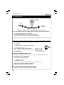
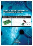
100W SUBWOOFER KIT
s to
abinet thank
c
ll
a
m
s
a
m
ss fro
Powerful ba
ker principle
e
th dual spea
Total solder points: 383
Difficulty level: beginner 1
2
3
4
5 ⌧ advanced
K8077
ILLUSTRATED ASSEMBLY MANUAL
H8077IP-1
Features & specifications
Features :
bass-reflex system with adjustable tube
compact size due to dual-speaker principle
adjustable level and filter response
auto power-on/off system
phase switch (0°-180°)
line level and speaker level inputs for maximum compatibility
'Full-range'-option for use in active speaker system
separate chamber for electronics avoids air leaks
Specifications
•
•
•
•
•
•
•
•
power output: 100Wrms/ 4ohm (10% THD)
filter freq. response:
wide: 25 - 110Hz (-6dB)
narrow: 18 - 65Hz (-6dB)
speakers: two 6.5" 8 ohm drivers
line level input sensitivity: 500mV
auto turn-on level: 5mV
volume*: approx. 20 liter
power supply: 120/230VAC
dimensions*: 460x310x210mm / 18,22 x 12,28 x 8,32"
(*) recommended enclosure. Drawings for enclosure are included
2
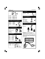
Assembly hints
1. Assembly (Skipping this can lead to troubles ! )
Ok, so we have your attention. These hints will help you to make this project
successful. Read them carefully.
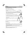
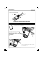
1.1 Make sure you have the right tools:
• A good quality soldering iron (25-40W) with a
small tip.
• Wipe it often on a wet sponge or cloth, to keep it clean; then apply solder to
the tip, to give it a wet look. This is called ‘thinning’ and will protect
the tip, and enables you to make good connections. When solder
rolls off the tip, it needs cleaning.
• Thin raisin-core solder. Do not use any flux or grease.
• A diagonal cutter to trim excess wires. To avoid injury when cutting
excess leads, hold the lead so they cannot fly towards the eyes.
• Needle nose pliers, for bending leads, or to hold components in place.
• Small blade and Phillips screwdrivers. A basic range
is fine.
For some projects, a basic multi-meter is required, or might
be handy
0.0
00
1.2 Assembly Hints :
⇒ Make sure the skill level matches your experience, to avoid disappointments.
⇒ Follow the instructions carefully. Read and understand the entire step before
you perform each operation.
⇒ Perform the assembly in the correct order as stated in this manual
⇒ Position all parts on the PCB (Printed Circuit Board) as shown on the drawings.
⇒ Values on the circuit diagram are subject to changes.
⇒ Values in this assembly guide are correct*
3
Assembly hints
⇒ Use the check-boxes to mark your progress.
⇒ Please read the included information on safety and customer service
* Typographical inaccuracies excluded. Always look for possible last minute
manual updates, indicated as ‘NOTE’ on a separate leaflet.
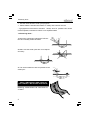
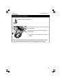
1.3 Soldering Hints :
1- Mount the component against the PCB surface and carefully solder the leads
2- Make sure the solder joints are cone-shaped
and shiny
3- Trim excess leads as close as possible to the
solder joint
AXIAL COMPONENTS ARE TAPED IN
THE CORRECT MOUNTING SEQUENCE !
REMOVE THEM FROM THE TAPE ONE AT
A TIME !
4
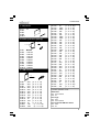
Construction
1. Jump wires.
J1 … J8
R3
R4
R8
R11
2. Diodes (check the polarity)
D ...
CATHODE
D1 : BAT85
D2 : 1N4148
D3 : 1N4148
D4 : 1N4148
D5 : 1N4007
D6 : 1N4007
D7 : 1N4007
D8 : 1N4007
D9 : 1N4007
D10 : 1N4007
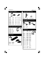
3. 1/4W resistors.
R...
R1
R2
R7
R12
R13
R14
R15
R16
R17
R18
R19
R20
R21
R22
:
:
:
:
:
:
:
:
:
:
:
:
22K
22K
47K
22K
22K
33K
22K
10K
22K
1K
10K
1K
: 1M
: 33K
(2 - 2 - 3 - B)
(2 - 2 - 3 - B)
(4 - 7 - 3 - B)
(2 - 2 - 3 - B)
(2 - 2 - 3 - B)
(3 - 3 - 3 - B)
(2 - 2 - 3 - B)
(1 - 0 - 3 - B)
(2 - 2 - 3 - B)
(1 - 0 - 2 - B)
(1 - 0 - 3 - B)
(1 - 0 - 2 - B)
(1 - 0 - 5 - B)
(3 - 3 - 3 - B)
R23
R24
R25
R26
R27
R28
R29
R30
R34
R35
R36
R37
R39
R40
R41
R42
R43
R44
R45
R46
R47
R48
R49
R50
R51
R52
R53
R54
R55
R56
R57
R58
R61
R62
:
:
:
:
:
:
:
:
:
:
:
:
:
:
:
:
:
:
:
:
:
:
:
:
:
:
:
:
:
:
:
:
:
:
1K
100K
390K
15K
470
15K
100K
100K
10K
10K
10K
10K
10K
100K
33K
100
47K
330
220
47
3K3
680
3K3
3K3
10
3K3
1K5
3K3
680
1K
220
47
1K8
470
(1 - 0 - 2 - B) *
(1 - 0 - 4 - B)
(3 - 9 - 4 - B)
(1 - 5 - 3 - B)
(4 - 7 - 1 - B)
(1 - 5 - 3 - B)
(1 - 0 - 4 - B)
(1 - 0 - 4 - B)
(1 - 0 - 3 - B)
(1 - 0 - 3 - B)
(1 - 0 - 3 - B)
(1 - 0 - 3 - B)
(1 - 0 - 3 - B)
(1 - 0 - 4 - B)
(3 - 3 - 3 - B)
(1 - 0 - 1 - B)
(4 - 7 - 3 - B)
(3 - 3 - 1 - B)
(2 - 2 - 1 - B)
(4 - 7 - 0 - B)
(3 - 3 - 2 - B)
(6 - 8 - 1 - B)
(3 - 3 - 2 - B)
(3 - 3 - 2 - B)
(1 - 0 - 0 - B)
(3 - 3 - 2 - B)
(1 - 5 - 2 - B)
(3 - 3 - 2 - B)
(6 - 8 - 1 - B)
(1 - 0 - 2 - B)
(2 - 2 - 1 - B)
(4 - 7 - 0 - B)
(1 - 8 - 2 - B)*
(4 - 7 - 1 - B)
(*) Select operation mode :
Subwoofer:
R61 : not mounted
R23 : 1K
Full range:
R61 : 1K8
R23 : not mounted
Full range with 6dB bass boost:
R61 : 1K8
R23 : 1K
5
Construction
4. Metallfilm resistors.
7. LEDs. Watch the polarity!
R...
LD1
CATHODE
R5
R6
: 100
: 470
(1 - 0 - 1 - B - 9)
(4 - 7 - 1 - B - 9)
R9 : 100
R10 : 470
(1 - 0 - 1 - B - 9)
(4 - 7 - 1 - B - 9)
R31 : 820
R32 : 820
R33 : 560
(8 - 2 - 1 - B)
(8 - 2 - 1 - B)
(5 - 6 - 1 - B)
R38 : 2K7
(2 - 7 - 2 - B - 9)
5. Zener diodes (check the polarity)
ZD...
ZD1 : 5V1
ZD2 : 5V1
CATHODE
LD3 : RED
(-35/+35VDC)
8. IC sockets. Watch the position
of the notch!
IC1 : 8p
IC2 : 14p
IC3 : 8p
9. Capacitors
ZD3 : 15V0
ZD4 : 15V0
C1 : 390pF (391)
C2 : 390pF (391)
ZD5 : 9V1
C3
C4
C5
C6
C7
C8
C9
C10
C11
C12
C13
6. Pinheaders
T7
T8
T9
: 5 pins
: 6 pins
: 6 pins
:
:
:
:
:
:
:
:
:
:
:
100nF
100nF
100nF
100nF
100nF
100nF
100nF
100nF
680pF
680pF
47nF
(104)
(104)
(104)
(104)
(104)
(104)
(104)
(104)
(680)
(680)
(473)
C14 : 47pF
C15 : 47pF
C16 : 47pF
(47)
(47)
(47)
C17 : 1nF
(102)
C18 : 100pF (101)
C19 : 10nF
6
(103)
c...
Construction
14. PCB tab
SK12 : GND
C20
C21
C22
C23
C24
:
:
:
:
:
0,047µF / 63V
0,068µF / 63V
4700pF/ 100V
0,022µF / 63V
0,022µF / 63V
15. Flat receptacles
10. Diodes (check the polarity)
D11
D12
D13
D14
:
:
:
:
1N5404
1N5404
1N5404
1N5404
LS+
LSAC BLUE
AC RED
AC GREY
AC YELLOW
SK...
CATHODE
16. Male board wire connector
D ...
SK11
11. Trim potentiometer
RV3 : 1K
R4
SK11
-
Turn RV3 fully
counterclockwise
:
:
:
:
:
:
BC547B
BC547B
BC640
BC640
BC557
BC639
-
+
SK11
-
+
-
+
SK11
-
+
-
+
Remark: if you wish to have a
‘POWER’ and ‘ON’ indication in a
remote location, you can remove the
shunts and connect the supplied female board to wire connector and two
extra LED’s
12. Transistors
T1
T2
T3
T4
T5
T6
+
T1
Wiring diagram:
Brown
cathode1
Red
anode1
Orange
Yellow
anode2
cathode2
ON
POWER
13. 5W resistors
R59 : 0,47
R60 : 0,47
R...
Ca
tho
de
2
Yellow
Orange
Red
Brown
An
od
e
Ca
tho
de
1
An
od
e
1
2
2mm
SK11
-
+
-
+
7
construction
17. Potentiometers
18. Electrolytic capacitors.
Watch the polarity !
C...
COMPONENT SIDE
RV1 : Stereo log. 50K
RV2 : Stereo log. 50K
C25 … C28
C29
C30 … C35
C36
:
:
:
:
10µF / 35V
22µF / 50V
100µF / 50V
470µF / 16V
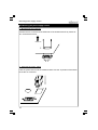
19. Switches
Fig 1.0
SW1 : Phase
SW2 : Mode
Position the switches onto the PCB first.
Mount a wire jumper onto each switch
connector and connect these with the switch
connector on the PCB.
CO
O
MP
NT
NE
DE
SI
Fig 1.0
8
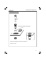
Construction
23. LEDs
20. Relais
LD1 : POWER
LD2: ON
RY1 : VR5V242C
( 24VDC - 5A - 2C)
21. Electrolytic capacitors.
Watch the polarity !
(red)
(red)
Mount both LEDs on the solderside
at 8mm of the PCB cathode is
marked with 'C'.
C37 : 3300µF / 50V
C38 : 3300µF / 50V
C...
22. Female cinch connectors
SOLDERSIDE
Cathode
Anode
SK...
SOLDERSIDE
MOUNT THEM ON THE
SOLDERSIDE !
8mm
Mount first :
SK1 : LOW LEVEL IN 'RIGHT'
SK3 : HIGH LEVEL IN 'RIGHT'
Mount now :
COMPONENT SIDE
SK2 : LOW LEVEL IN 'LEFT'
SK4 : HIGH LEVEL IN 'LEFT'
SK ...
Inspect the complete assembly.
Once the PCB is mounted on the
heatsink, the solderside is no
longer accessible.
9
Fixing the knobs
24. Fixing the knobs
Slide the knobs fully onto the potentiometer axes.
Turn potentiometers fully counterclockwise
Watch the position of
the dot !
10
!
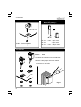
Fixing the PCB
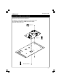
25. Fixing the PCB onto the heatsink
Fixing the PCB onto the heatsink :
(1) Slide 2 x 5mm plastic spacers over the black bolts.
(2) Carefully position the PCB onto the two bolts
(3) fasten using two nuts.
M3 nut
Spacer
M3 bolt 16mm
11
Fixing the PCB
Tighten gently, making sure that :
•
•
•
•
the leds protrude the holes
the cinch (RCA) connectors do not touch the heatsink
the knobs do not touch the heatsink
the switches do not touch the heatsink
(4) fit the remaining bolts and spacers
(5) fit the nuts and tighten them all, while minding the position of the knobs,
switches, leds and connectors
5X
12
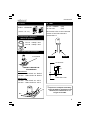
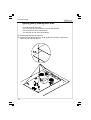
Fixing power transistors
26. Fixing the power transistors T8 (TIP147) & T9 (TIP142)
bend both transistors as indicated.
+/
m
-5
m
apply a drop of heat conductive compound on the heatsink.
position the mica onto the heatsink so that the hole coincide with the hole in
the heatsink, press gently.
• apply a drop of heat conductive compound on the mica.
• Mount the transistor on the heatsink, using a 16mm bolt, lock washer and nut.
•
•
Make sure the transistor leads are correctly positioned
between the pins of the pinheader.
•
Tighten gently.
M3 nut
Lock washer
T8 (TIP147)
mica
Heat conductive
compound
M3 bolt
13
Fixing Diode D15
•
Solder the transistor leads
Repeat for the remaining transistor T9 (TIP142)
27. Fitting diode D15 (1N4007)
Bend the leads as indicated.
Put a large drop of heat conductive
compound on the heatsink.
Solder the diode to the two outer pins of
the pin header.
Make sure that the diode is bend towards the heat conductive compound.
!
14
Mind the direction of the ring. It should
face transistor T9
Fitting transistor T7
28. Fitting transistor T7 (BC547)
Bend the leads as indicated.
Put a large drop of heat conductive compound
on the heatsink.
Solder the transistor to the remaining pins of
the pinheader.
The flat side of the transistor must face the
heatsink.
Make sure that the transistor and diode leads do not touch each other
and make sure that the diode does not touch the power transistor.
15
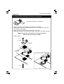
Mounting power supply section
29. Mounting the power supply section
1. Mounting the AC connector
Position the AC connector at the PCB side of the heatsink and fix by means of
two 10mm black screws.
10mm screw
2. Mounting the power switch
Click the power switch onto the heatsink. Make sure the '0'-position of the switch
faces the AC connector.
16
Mounting power supply section
3. Mounting the fuse holder
2A T
If necessary , enlarge mounting hole
Place the fuse holder and fix with the included nut.
Place a 2A T fuse.
17
Mounting power supply section
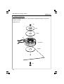
4. Fixing the transformer
Rotate the transformer in such a way that the red/yellow/blue/grey wires point
towards the PCB.
Tighten the nut
nut
disk
washer
transformer
washer
bolt
18
Mounting power supply section
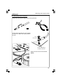
5. Wiring the ground connection
Connect one end of the cable to the red ring terminal.
1
2
Connect the ring terminal to the chassis
by means of a black bolt, spring washer
and nut.
M3 nut
spring washer
16mm M3 bolt
Scratch off anodizing
for better conduction
Solder the other end to the PCB tab
(SK12)
19
Mounting power supply section
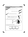
6. Transformer wiring (red/yellow/blue/grey wires)
Slide an insulation sleeve over each wire.
Solder a connector to each wire
SOLDER
Slide the sleeve over the connector
REMARK : In case you trim the wires, always
remove the insulating lacquer (+/- 1cm)
•
Connect the wires to the PCB. Mind the colours!
RED
BLUE
GREY
YELLOW
•
Group the wires by means of two cable ties
•
Cut the largest of the two heatshrink tubes into 3 pieces: 3cm - 3cm - 4cm
3cm
20
3cm
4cm
Mounting power supply section
•
Trim the black transformer wire to a length of 14cm. Slide a piece of heatshrink
tube (3cm) over the black transformer wire.
120VAC : ORANGE
Unused
lead
235VAC : BROWN
120VAC : BROWN
235VAC : ORANGE
BLACK
BLACK
BLACK
HEATSHRINK TUBE
•
Solder the wire to the AC connector
•
Use the remaining black wire to connect the second AC connector lug with the
center connector of the fuse holder.
Don't forget to slide a piece of heatshrink tube (4cm) over the wire.
•
Connect the remaining fuseholder-connector with the power switch.
•
Don't forget the heatshrink tube.
Depending on your local AC voltage, connect either the brown wire (100-120VAC)
or the orange wire (220-245VAC) to the power switch.
Don't forget the heatshrink tube.
•
Trim the remaining wire to a lenght of 11cm. Insulate the end by means of a piece
of heatshrink tube.
•
Group the wires by means of two cable ties.
21
Testing the unit
30. Testing the unit
60W
(120 / 235VAC)
From K8077
Power supply
120 / 235VAC
Make sure that the IC’s are removed from their sockets.
We recommend to construct a small test-jig, and connect the unit as shown below.
1. Put the power switch in the ‘I’ position
2. Put the ‘MODE’-switch in the ‘AUTO-ON’-position.
3. When power is applied, the ‘POWER’ led should light.
If the light bulb remains lit, turn off the power immediately and check your circuit.
By means of a multi meter set to DC volts, you can check the following voltages:
Use the GND tab next to the red transformer wire as ‘-‘
• J2: +15V
• J3: -15V
• Left lead of R33: +24V or slightly higher
• Right lead of R37: +5V
IC1 : TL072
4. Turn off the power and mount the IC’s.
IC2 : TL074
5. Turn on the power again repeat the above
IC3 : VK8077
measurements.
(programmed PIC10F200-I/PG)
If OK, flip the ‘MODE’-switch to ‘ON’
Once again, if the light bulb remains lit, turn off the power immediately and
check your circuit. LD3 should light.
Check the following voltages:
• Cathode D11: +35V
• Anode D12: -35V
6. Connect the multimeter across R60 (right power resistor).
7. Meter should read 0V (Mind the polarity) !
8. Adjust RV3 until the meter reads 10mV
Wait a while until the readout remains constant
9. Remove the multimeter and turn off the power
22
Enclosure assembly
31. Assembly of the enclosure
Refer to the included mounting instructions.
(A)
Mark all holes according to the diagram. Use a 2mm drill to pre-drill the holes
(B)
Mark the two holes for the speakers, as indicated.
Mark the hole for the reflex tube, as indicated
Carefully cut-out the holes using an electric jigsaw
If necessary, smooth the edges with sanding paper
(C)
Mark the position of the wooden supports for the heatsink. (5mm from edge)
(D)
Cut 4 pieces of 10x15mm wood (2 x 174mm, 2 x 131mm)
(E)
Pre-drill 2 holes in each wooden support, 20mm from edge and in the center
(F)
Pre-drill two 3,5mm holes in the backside of the housing according to the
diagram.
(G)
- Fix the wooden supports using two screws and glue.
- Assemble the enclosure, according to the drawings 1 to 3
- Fix the bass reflex tube, according to drawing 4
(H)
Drawing 1 :
- Position both speakers in such a way that their connectors face each
other. Mark the holes and remove the speakers.
- Pre-drill the holes with a 2mm drill.
Drawing 2 :
- cut 20 cm red and 20 cm black wire. Solder the red wire to the '+'
terminal of a speaker, solder the black wire to the '-' terminal of the
speaker.
Drawing 3 :
- Put some silicone adhesive round the speaker hole closest to the bass
tube. Fix the speaker using the supplied 25mm screws.
- Solder the red wire from the mounted speaker and the remaining red wire
to the '+' of the second speaker.
- Solder the black wire from the mounted speaker and the remaining black
wire to the '-' of the second speaker.
- Guide the red and black wire trough the 3.5mm holes of the enclosure
(6).
- Put some silicone adhesive round the speaker hole closest to the bass
tube. Fix the speaker using the supplied 25mm screws.
23
Enclosure assembly
(I)
- Fix the speaker wires with some glue and trim them to a length of 20cm
- Slide an insulating sleeve over both wires. Solder a connector to both
wires and slide the insulating sleeves over the connector.
- Fix the 4 plastic feet by means of a 23mm screw and put the enclosure
on its feet.
(J)
- put the heatsink in place and mark the 10 holes.
- remove the heatsink
- pre-drill the holes with a 1.5mm drill
- connect the red speaker wire to the connector marked 'LS+'
- connect the black speaker wire to the connector marked 'LS-'
- Carefully put the amplifier module in place.
- Fix the heatsink using ten 10mm black screws
24
Placement
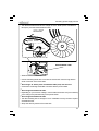
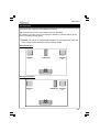
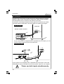
32. Placement
For best results, experiment with different positions.
We recommend to put the unit between the main speakers.
The closer to a wall or corner, the higher the efficiency (volume) will be, at the
cost of a reduced sound quality.
Remark: The unit is not magnetically shielded. Do not operate the unit in the
close vicinity of CRT television sets or magnetic media.
Central position :
Speaker
L
Subwoofer
Speaker
R
Decentral position :
Speaker
L
Subwoofer
Speaker
R
25
Connection
33. Connection
Just below the power switch you will notice two AC voltage indications (120VAC235VAC). Strike out the one that does not apply with a black permanent marker.
Use the supplied cord to connect the unit to the AC power grid.
If necessary, cut the plug and replace it with a plug (not incl.) that fits your outlets.
The audio inputs accept either a line level signal or a speaker level signal.
LINE LEVEL SIGNAL
SUBWOOFER
AMPLIFIER - PREAMP - RECEIVER - ...
L
R
LINE IN
SPEAKER IN
L
R
ADJ. Line OUT
If your audio system is equipped with an adjustable line level output, you can
connect it to the 'LINE IN'-inputs of the subwoofer.
SPEAKER LEVEL SIGNAL
+
L
R
LINE IN
SPEAKER IN
L
To speaker
L
R
To speaker
R
If your system is not equipped with an adjustable line level output, connect the
'SPEAKER-IN'-inputs in parallel with the main speaker outputs of your amplifier.
!
26
Never use both inputs simultaneously
Use
34. Use
Turn the volume control (OUTPUT LEVEL) fully counter clockwise before first
power-on.
• Turn-on the 'POWER'-switch. The 'POWER'-led will light.
•
The unit will either immediately turn on ('ON'), or wait for an incoming audio signal ('AUTO-ON'), depending on the position of the 'MODE'-switch.
If 'AUTO-ON' has been selected, the unit will automatically turn-on when an
audio signal is present. If the audio signal is absent for a while (e.g. because
the source has been turned off), the unit will return to the standby mode.
Put on your favourite music and adjust the volume of the main speakers.
Adjust the volume control of the subwoofer (OUTPUT LEVEL) to an appropriate
level. You can adapt the response curve to your personal taste by turning
'FILTER ADJUST'.
Make sure to try both positions of the 'PHASE'-switch. Only one position will
give the best result.
27
PCB
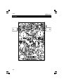
35. PCB
28
RED
GREY
YELLOW
BLUE
SK10
SK9
SK8
SK7
GND
D10
D9
GND
4x1N4007
D7
D8
C33
100µF/50V
ZD3
15V
820/0.6W
R32
15V
C32
100µF/50v
2K7 0.6W
R38
560
ZD4
820/0.6W
R31
GND
C34
100µF/50V
1N4007
D6
R33
-15V
+15V
GND
5V1
ZD1
R37
10K
GND
100n
C8
C19
10n
auto
GND
GND
10µF
C27
2
GND
ON
D2
1N4148
10K
R34
RELAY VR5V242C
R36
10K
GND
R40
100K
10K
R39
SW TS-4
SW2
bridge if not connected
remote power/on leds
LD2
GP1/ICSPCLK 4
VSS
7
IC3
PIC10F200-I/PG
5 GP0/ICSPDAT
SK11
4 3 2 1
8 GP3/MCLR/VPP
3 GP2/T0CLKI/FOSC4
VDD
GND
R35
10K
LD1
POWER
yellow
GND
T1
BC547
PSU :
100µF/50V
C31
100Á/50V
C30
1N4007
D5
RY1
blue
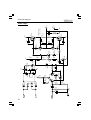
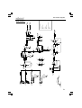
Schematic diagram
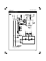
36. Schematic diagram
29
30
C14
47p
S_GND
amp
blue
yellow
GND
R43
47K
10µF
C28
R42
100R
R47
3K3
BC640
C36
680R
R48
R49
3K3
R52
3K3
+40V
GND
C37
-40V
T4
BC640
4700µF/50V
C38
4700µF/50V
470µF/16V
T3
ZD5
ZB9V1
GND
1N5404
D11
1N5404
D12
1N5404
D13
1N5404
D14
3K3
R50
C15
47p
C35
100µF/50V
-40V
C10
100nF
C9
100nF
+40V
47p
C16
-40V
BC639
T6
R56
1K
1K
R55
680
R54
3K3
R53
1K5
+40V
RV3
Bias adj.
LD3
LED3RL
R41
33K
330R
R44
D15
1N4148
T7
BC547
T2
BC547
D4
1N4148
T5
BC557
D3
1N4148
R46
47R
R58
47R
C11
680p
220R
R45
220R
R57
680p
C12
C13
T8
-40V
TIP147
GND
R51
10
R59
0.47 / 5W 47nF
R60
0.47 / 5W
SK6
SK5
GND
10-15mV over R60
Bias current (cold)
T9
TIP142
+40V
LS-
LS+
Schematic diagram
Power stage :
SK12
S_GND
S_GND
Connect to chassis ground
High in (R)
SK4
High in (L)
SK3
Low in (R)
SK1
SK2
Low in (L)
4K7
R3
470
R8
1K
1K
1K
S_GND
R5
1K
R9
R4
S_GND
S_GND
4K7
4K7
R62
R6
4K7
R11
R10
C2
390p
C1
390p
R1
filter
22K
R13
22K
R12
22K
R2
22K
22n
C24
S_GND
9
10
IC2C
TL074
8
S_GND
High pass (30Hz)
390K
R25
C4
100n
-15V
1
C3
100n
+15V
R7 47K
(gain:=x2)
-15V
4
IC1A
TL072
8
S_GND
2
R24 100K
22n
C23
4n7
C22
S_GND
3
+15V
C6
100n
33K
R22
-15V
10K
22K
C5
100n
+15V
R16
R15
RV2B
50k log
100K
R30
0/180°
SW1
SW TS-4
IC1B
TL072
22K
S_GND
5
6
R17
10µF
C26
C29
C21
68n
1M
1
10µF
C25
13
12
+15V
4
11
IC2D
TL074
-15V
R23
S_GND
(*)
1K
auto
15K
R28
D1
BAT85
1n
C17
C18
100p
S_GND
14
ZD2
5V1
S_GND
10K
R29
100K
470
R27
R19
S_GND
C20
47n
RV2A
50k log
Low pass
33K
Filter slope adj
S_GND
R14
R21
IC2A
TL074
S_GND
Level
RV1A
22µF/63V
1K
R20
2
3
C7
100n
1K
R18
S_GND
7
6
5
15K
amp
R26
IC2B
TL074
R61
(*)
1K8
amp
filter
R23: 1K
Full range with 6dB bass boost:
R61: 1K8
R61: 1K8
R23: not mounted
Full range:
R23: 1K
R61: not mounted
Subwoofer:
(*) Select operation mode:
7
Schematic diagram
Filter section :
31
VELLEMAN KIT NV
Legen Heirweg 33
9890 Gavere
Belgium Europe
Info ?: http://www.velleman.be
Modifications and typographical errors reserved
© Velleman Kit nv
H8077IP - 2006 - ED1 (rev 3.0)
5 410329 359676