1
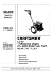
Owner's
Manual
CRRFTSMRH°
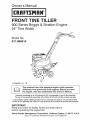
FRO T TI
E T LL
900 Series Briggs & Stratton Engine
24" Tine Width
Model No.
917,986910
Espar_ol, p. 19
This product has a low emission engine which operates
differently from previously built engines. Before you start
the engine, read and understand this Owner's Manual.
Gasoline containing up to 10% ethanol (EIO) is acceptable for use in this machine.
The use of any gasoline exceeding 10% ethanol (EIO) will void the product warranty.
Esta m_quina puede utilizar gasolina con un contenido de hasta el 10% de etanol (EIO).
El uso de una gasolina que supere el 10% de etanol (El0) anular_ la garantia del producto.
IMPORTANT:
Read and follow all Safety Rules and Instructions
before operating this equipment.
Sears Brands
Management
Corporation,
Visit our Craftsman
Hoffman
Estates, IL 60179 U.S.A.
website:www.sears.com/craftsman
Warranty .................................................
2
Safety Rules ........................................
2-3
Product Specifications
...........................
4
Assem bly/Pre-Operation
.....................
5-6
Operation
..........................................
7-10
Maintenance
Schedule
........................
11
Craftsman
Professional
Maintenance
....................................
11-13
Service and Adjustments
................ 14-15
Storage .................................................
16
Troubleshooting
..............................
17-18
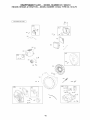
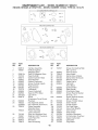
Illustrated
Parts List .........................
36-47
Sears Service ........................
Back Cover
Riding Equipment
Full Warranty
FOR TWO YEARS from the date of purchase, all non-expendable parts of this riding equipment are
warranted against any defects in material or workmanship. A defective non-expendable
part will
receive free in-home repair or replacement if repair is impossible.
FOR FIVE YEARS from the date of purchase, the frame and front axle of this riding equipment are
warranted against any defects in material or workmanship. A defective frame or front axle will receive
free in-home repair or replacement if repair is impossible.
All of the above warranty coverage applies for only one year from the date of purchase if this riding
equipment is ever used while providing commercial services or if rented to another person.
FOR 90 DAYS from the date of purchase, the battery (an expendable part) of this riding equipment
is warranted against any defects in material or workmanship (our testing proves that it will not hold
a charge). A defective battery will receive free in-home replacement.
ADDiTiONAL
LiFETiME LiMiTED WARRANTY on CAST iRON FRONT AXLE (if equipped)
FOR AS LONG AS IT IS USED by the original owner after the fifth year from the date of purchase, the
cast iron front axle (if equipped) of this riding equipment is warranted against any defects in material or
workmanship. With proof of purchase, a defective cast front axle will receive free in-home replacement.
WARRANTY SERVICE
For warranty coverage details to obtain free
• Repairs
necessary
because
of operator
repair or replacement,
call 1-800-659-5917 or
abuse, including but not limited to damage
visit the web site: www. craftsman.com
caused
by towing
objects
beyond
the
capability of the riding equipment, impacting
In all cases above, if part repair or replacement
objects that bend the frame, axle assembly or
is impossible,
the riding equipment
will be
crankshaft, or over-speeding the engine.
replaced free of charge with the same or an
=
Repairs
necessary
because
of operator
equivalent model.
negligence,
including
but
not
limited to,
This warranty covers ONLY defects in material
electrical
and
mechanical
damage
caused
and workmanship.
Warranty coverage
does
by improper storage, failure to use the proper
NOT include:
grade and amount of engine oil, failure to
• Expendable parts (except for battery) that can
keep the deck clear of flammable debris,
wear out from normal use within the warranty
or failure to maintain the riding equipment
period, including but not limited to blades,
according to the instructions contained in the
spark plugs, air cleaners, belts, and oil filters.
operator's manual.
• Standard maintenance servicing, oil changes,
= Engine (fuel system) cleaning or repairs
or tune-ups.
caused by fuel determined to be contaminated
• Tire replacement
or repair
caused
by
or oxidized (stale). In general, fuel should be
punctures from outside objects, such as
used within 30 days of its purchase date.
nails, thorns, stumps, or glass.
= Normal deterioration and wear of the exterior
• Tire or wheel replacement or repair resulting
finishes, or product label replacement.
from normal wear, accident,
or improper
This warranty gives you specific legal rights, and
operation or maintenance.
you may also have other rights which vary from
state to state.
Sears
Brands
Management
Corporation,
Hoffman
Estates,
IL 60179
IMPORTANT:
This cutting machine
is capable of amputating
hands and feet and throwing objects.
Failure to observe the following
safety instructions
could result in serious
injury or death.
TRAINING
Read the Owner's Manual carefully. Be
thoroughly familiar with the controls and
the proper use of the equipment. Know 2
how to stop the unit and disengage
the
controls quickly.
Never allow children to operate the equipment. Never allow adults to operate the
equipment
without proper instruction.
• Keep the area of operation
persons, particularly
small
pets.
clear of all
children,
and
Disconnect
the spark plug wire, and
keep the wire away from the plug to
prevent accidental
starting. Disconnect
the cord on electric motors.
PREPARATION
• Do not run the engine indoors; exhaust
fumes are dangerous.
• Never operate the tiller without proper
guards, plates, or other safety protective devices in place.
• Keep children and pets away.
• Do not overload the machine
capacity
by attempting
to till too deep at too fast
a rate.
• Thoroughly
inspect the area where the
equipment
is to be used and remove all
foreign objects.
• Disengage
all clutches and shift into neutral before starting the engine (motor).
• Do not operate the equipment
without wearing adequate
outer garments.
Wear footwear that will improve footing
on slippery surfaces.
• Handle fuel with care; it is highly flammable.
• Use an approved
fuel container.
• Never add fuel to a running engine
hot engine.
• Fill fue! tank outdoors
with extreme
care. Never fill fuel tank indoors.
• Never operate the machine at high
speeds on slippery surfaces.
Look
behind and use care when backing.
• Never allow bystanders
near the unit.
• Use only attachments
and accessories
approved
by the manufacturer
of the
tiller.
or
• Never operate the tiller without good
visibility
or light.
• Be careful when tilling in hard ground.
The tines may catch in the ground and
propel the tiller forward.
If this occurs,
let go of the handlebars
and do not
restrain the machine.
• Replace gasoline cap securely and
clean up spilled fue! before restarting.
• Use extension
cords and receptacles
as specified
by the manufacturer
for
all units with electric drive motors or
electric starting motors.
• Never attempt to make any adjustments
while the engine (motor) is running
(except where specifically
recommended by manufacturer).
MAINTENANCE
• Keep machine,
attachments,
and accessories
in safe working
condition.
• Check shear pins, engine mounting
bolts, and other bolts at frequent
intervals for proper tightness
to be sure the
equipment
is in safe working
condition.
• Never store the machine with fuel in
OPERATION
• Do not put hands or feet near or under
rotating parts.
• Exercise extreme caution when operating on or crossing
gravel drives, walks,
or roads. Stay alert for hidden hazards
or traffic. Do not carry passengers.
• After striking a foreign object, stop the
engine (motor), remove the wire from
the spark plug, thoroughly
inspect the
tiller for any damage,
and repair the
damage
before restarting
and operating
the tiller.
• Exercise caution
falling.
• If the unit should
to avoid
slipping
start to vibrate
AND STORAGE
the fuel tank inside a building where
ignition sources are present, such as
hot water and space heaters, clothes
dryers, and the like. Allow the engine to
cool before storing in any enclosure.
• Always refer to the operator's
guide
instructions
for important
details if the
tiller is to be stored for an extended
period.
_Look
for this symbol to point out
important
safety precautions.
It means
CAUTION!!!
BECOME ALERT!!!
YOUR
SAFETY IS INVOLVED.
or
ab-
normally, stop the engine (motor) and
check immediately
for the cause. Vibration is generally a warning of trouble.
• Stop the engine (motor) when leaving
the operating
position.
• Take all possible
precautions
when
leaving the machine
unattended.
Disengage the tines, shift into neutral, and
stop the engine.
• Before cleaning,
repairing,
or inspecting, shut off the engine and make
certain all moving parts have stopped.
_,CAUTION:
Always disconnect
spark
plug wire and place wire where it cannot
contact spark plug in order to prevent
accidental
starting when setting up, transorting, adjusting
or making repairs.
WARNING:
Engine exhaust, some of
its constituents,
and certain vehicle components contain or emit chemicals
known
to the State of California
to cause cancer
3
and birth defects
harm.
or other
reproductive
PRODUCT
Gasoline
SPECIFICATIONS
Capacity:
REPAIR PROTECTION
AGREEMENTS
2.9 Quarts
Unleaded Regular
Oil (API SG-SL):
SAE 30 Above 32°F/0°C
(Capacity:
SAE5W30Below32°F/0°C
20 oz.)
Spark Plug:
Champion
Congratulations
on making a smart purchase. Your new Craftsman®
product is
designed and manufactured
for years of
dependable
operation. But like all products,
it may require repair from time to time. That's
when having a Repair Protection Agreement
can save you money and aggravation.
Purchase
a Repair Protection
Agreement
now and protect yourself from unexpected
hassle and expense.
Here's what's included in the Agreement:
•
Expert service by our 12,000 profesional repair specialists.
•
Unlimited
service and no charge for
parts and labor on all covered
repairs.
•
Product replacement
if your covered
product can't be fixed.
•
Discount
of 10% from regular price of
service and service-related
parts not
covered by the agreement;
also, 10%
off regular price of preventive
maintenance check.
•
Fast help by phonephone support
from a Sears technician
on products
requiring
in-home repair, plus convenient repair scheduling.
Once you purchase
the Agreement,
a
simple phone call is all that it takes for you
to schedule
service. You can call anytime
day or night, or schedule
a service appointment
online.
Sears has over 12,000 professional
repair
specialists,
who have access to over 4.5
million quality parts and accessories.
That's the kind of professionalism
you can
count on to help prolong the life of your
new purchase
for years to come. Purchase your Repair Protection
Agreement
today!
RC12YC
(Gap: .030")
CONGRATULATIONS
on your purchase
of a Sears Tiller. It has been designed,
engineered
and manufactured
to give you
the best possible
dependability
and performance.
Should you experience
any problems
you
cannot easily remedy, please contact a
Sears or other qualified Service Center.
We have competent,
well-trained
technicians and the proper tools to service or
repair this unit.
Please read and retain this manual. The
instructions will enable you to assemble
and maintain your tiller properly. Always
observe the "SAFETY RULES".
Your new tiller has been assembled
at the
factory with exception
of those parts left
unassembled
for shipping
purposes.
To
ensure safe and proper operation
of your
tiller all parts and hardware you assemble
must be tightened
securely.
Use the correct tools as necessary
to insure proper
tightness.
CUSTOMER
RESPONSIBILITIES
• Read and observe the safety rules.
• Follow a regular schedule
in maintaining, caring for and using your tiller.
• Follow the instructions under the "Maintenance"
Owner's
and "Storage"
Manual.
sections
of this
_WARNING:
This unit is equipped
with
an internal combustion
engine and should
not be used on or near any unimproved
forest-covered,
brush-covered
or grass
covered land unless the engine's
exhaust
system is equipped
with a spark arrester
meeting applicable
local or state laws (if
any). If a spark arrester is used, it should
be maintained
in effective working
order
by the operator.
In the state of California
the above is
Some limitations
and exclusions
apply.
For prices and additional information
call 1-800-827-6655.
SEARS INSTALLATION
SERVICE
For Sears professional
installation
of home
appliances,
garage door openers, water
heaters, and other major home items, in
the U.S.A. call 1-800-4-MY=HOME®
required
by law (Section 4442 of the
California
Public Resources
Code).
Other
states may have similar laws. Federal
laws apply on federal lands. A spark arrester for the muffler is available through
your nearest Sears service center
(See
REPAIR PARTS section of this manual).
4
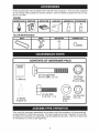
These accessories
were available when the tiller was produced.
at most Sears retail outlets and service centers.
Some of these
ply to your tiller.
They are also available
accessories
may not ap-
ENGINE
SPARK PLUG
TILLER
MUFFLER
AIR FILTER
GAS CAN
ENGINE OIL
STABILIZER
MAINTENANCE
BELT
%
TINES
SHEAR PIN
HAIRPIN CLIP
C')
i
CONTENTS OF HARDWARE PACK
(2) Carriage Bolts
5/16-18 UNC x 2-1/2
(2) Flange
Locknuts
5/16-18 UNC
(1) Manual
(2) Hex Bolt
5/16-18 x 1-1/4
(1) Bottle
Engine Oil
(2) Lock
Washer
5/16
(2) Hex Nut
5/16-18
Your new tiller has been assembled
at the factory with the exception
of those parts left
unassembled
for shipping
purposes.
To ensure safe and proper operation
of your tiller
all parts and hardware
you assemble
must be tightened
securely.
Use the correct tools
as necessary
to insure proper tightness.
5
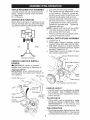
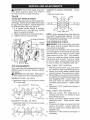
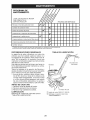
TOOLS REQUIRED
A socket wrench
easier. Standard
FOR ASSEMBLY
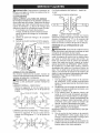
1. Cut cable ties securing
handles.
2. The handle may be assembled
in high
or low position.
Slowly lift handle assembly up and align handle holes with
desired handle panel hole and slot.
3. Loosely assemble
hardware
as shown.
Be sure the shorter (1" long) hex bolt
is assembled
in lower hole of handle.
set will make assembly
wrench sizes are listed.
(1) Utility knife
(2) 1/2 Wrench
OPERATOR'S
POSITION
When right or left hand is mentioned in this
manual, it means when you are in the operating position (standing behind tiller handles).
Repeat for opposite
side.
Tighten all
hardware
securely.
NOTE: Cables must not touch the muffler.
Front
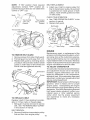
4.
Cut cable ties securing tiller to skid
and remove tiller from skid.
5.
Remove screws securing
depth
to skid and discard screws.
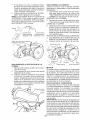
INSTALL
1.
2.
Left
3.
Right
4.
Operator's
UNPACK
CARTON
DEPTH
STAKE
Engine Bracket Halves
Nut "A"
Position
& INSTALL
epth Stake Support
_:_,CAUTION:
Be careful of exposed
staples when handling
or disposing
of
cartoning
material.
IMPORTANT:
When unpacking
and assembling
tiller, be careful not to stretch or
Handle Panel _
ASSEMBLY
Loosen nut "A".
Insert stake support
between
engine
bracket halves with stake spring down.
Bolt stake support
to engine
brackets
with bolts, Iockwashers
and nuts. Tighten
securely. Tighten nut "A".
Depth stake must move freely. If it does
not, loosen support bolt.
HANDLE
kink cable(s).
stake
_
.........
_
Support
Tiller Handle
............
_Stake
Spring
Hex Bolts,
Lock Washers, and Hex Nuts
HANDLE
HEIGHT
• Handle height may be adjusted
suit operator.
(See "HANDLE
in the Service and Adjustments
of this manual).
TILLING
to better
HEIGHT"
section
WIDTH
• Tilling width may be adjusted
to better
handle your tilling conditions
(See "TINE
ARRANGEMENT"
in the Service
and
Adjustments
section
of this manual).
TINE OPERATION
• Checktine operation before first use. (See
"TIN E OPERATION CHECK" in the Service
and Adjustments section of this manual).
6
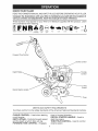
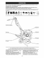
KNOW YOUR TILLER
READ THIS OWNER'S MANUALAND
SAFETY RULES BEFORE OPERATING YOUR TILLER.
Compare the illustrations with your tiller to familiarize yourself with the location of
various controls and adjustments. Save this manual for future reference.
These symbols
and understand
may appear on your Tiller or in literature
their meaning.
FN
TILLING
FORWARD
NEUTRAL
supplied
with the product.
Learn
-,,,
REVERSE
CAUTION
OR WARNING
ENGINE
ON
ENGINE
EAST
SLOW
CHOKE
FUEL
OIL
STOP
U
OFF
Forward Tine Control
Choke Control
Depth Stake
Throttle
Control
Tine
Shield
Recoil Starter Handle
O
Tines
MEETS ANSI SAFETY REQUIREMENTS
Our tillers conform to the safety standards of the American National Standards
tines in forward direction.
RECOIL STARTER
HANDLE
CHOKE CONTROL = Used when starting
a cold engine.
DEPTH STAKE = Controls forward speed
and the depth at which tiller will dig.
FORWARD TINE CONTROL = Engages
start the engine.
THROTTLE
CONTROL
engine
7
speed.
Institute.
= Used to
= Used to control
The operation of any tiller can result in foreign objects thrown into the eyes,
which can result in severe eye damage. Always wear safety glasses or eye
shields before starting your tiller and while tilling. We recommend standard
safety glasses or a wide vision safety mask worn over spectacles.
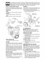
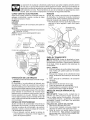
HOW TO USE YOUR TILLER
WHEELS
Know howto operate all controls before adding fuel and oil or attempting
to start engine.
Adjust wheels by removing
the hairpin
and clevis pin. Change wheel position.
place the hairpin clip and clevis pin.
• Fornormaltilling,
setwheelsatthesecond
or third hole from the top.
STOPPING
TINES
• Release
ENGINE
tine control
• Move throttle
tion.
NOTE:
Never
to stop movement.
control
to "STOP"
use choke
Hairpin Clip
and Clevis Pin
posi-
to stop engine.
Tine Control
"Off" (UP)
Position
Choke Control
clip
Re-
Tine Control
"On" (DOWN)
Position
Throttle Control
Wheels
and Clevis Pin
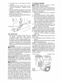
TO TRANSPORT
,_CAUTION:
Before lifting or transporting, allow tiller engine and muffler to
cool.
Disconnect
spark plug wire. Drain
gasoline from fuel tank.
AROUND
THE YARD
1. Tip depth stake forward until it is held by
the stake spring.
2. Push tiller handles down, raising tines
off the ground.
3. Push or pull tiller to desired location.
AROUND
TOWN
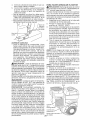
TINE OPERATION
• Squeeze
tine control
to handle.
TILLING
The speed and depth of tilling is regulated
bythe position of the depth stake and wheel
height.
The depth stake should always be belowthe
wheels for digging.
It serves as a brake to
slow the tiller's forward motion to enable the
1.
2.
Disconnect
spark
Drain fuel tank.
3.
Transport
in upright
oil leakage.
BEFORE STARTING
position
to prevent
ENGINE
iMPORTANT:
Be very careful not to allow
dirt to enter the engine when checking
or
adding oil or fuel. Use clean oil and fuel and
store in approved,
clean, covered containers. use clean fill funnels.
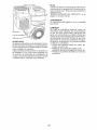
FILL ENGINE WITH OIL
tinesto penetrate the ground. Also, the more
the depth stake is lowered into the ground
the deeper the tines will dig.
,
DEPTH STAKE
Adjust depth stake by removing
the hairpin
clip and clevis pin. Change depth stake to
desired
position.
Replace
the clevis pin
and hairpin clip.
• For normal tilling, set depth stake at the
second or third hole from the top.
plug wire.
2.
.
8
Remove hangtag from engine.
With engine level, remove engine oil filler
plug.
Fill engine with oil to point of overflowing.
For approximate
capacity
see
"PRODUCT SPECIFICATIONS"
on page
4 of this manual. All oil must meet A.RI.
Service
Classification
SG-SL.
4. Tilt tiller back on its wheels and then
re-level.
5. With engine level, refill to point of overflowing if necessary. Replace oil filler
plug.
For cold weather operation you should
change oil for easier starting (See "OIL
VISCOSITYCHART" in the Maintenance
section of this manual).
Tochangeengineoil,seethe Maintenance
section of this manual.
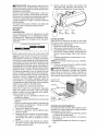
TO START ENGINE
_I, CAUTION:
Keep tine control in "OFF"
position when starting engine.
When starting engine for the first time or if
engine has run out of fuel, it will take extra
pulls of the recoil starter to move fuel from
the tank to the engine.
1. Make sure spark plug wire is properly
connected.
2. Place throttle control in "FAST" position.
3. Movechokecontroltofull"CHOKE"position. Grasp recoil starter handle with one
hand and grasp tiller handle with other
hand. Pull rope out slowly until engine
reaches start of compression cycle (rope
will pull slightly harder at this point).
4. Pull recoil starter handle quickly.
Do
not let starter handle snap back against
starter. Repeat if necessary.
NOTE: If engine fires but does not start,
move choke control to half choke position.
Pull recoil starter handle until engine starts.
5. When engine starts, slowly move choke
control to "RUN" position as engine
warms up.
NOTE: A warm engine requires less choking to start.
6. Move throttle control to desired running
position.
7. AIIowenginetowarm
upforafewminutes
before engaging tines.
NOTE: If at a high altitude (3000 feet) or
in cold temperatures (below 32°F/0°C), the
carburetor fuel mixture may need to be
adjusted for best engine performance.
See
"TO ADJUST CARBURETOR" in the Service
and Adjustments section of this manual.
NOTE: If engine does not start, see troubleshooting points.
ADD GASOLINE
Fill fuel tank to bottom
of filler
neck.
Do
not overfill.
Use fresh, clean, regular
unleaded
gasoline
with a minimum
of
87 octane.
(Use of leaded gasoline will
increase carbon and lead oxide deposits
and reduce valve life). Do not mix oil with
gasoline.
Purchase fuel in quantities that
can be used within 30 days to assure fuel
freshness.
_ILCAUTION:
Fill to within 1/2" of top of fuel
tank to prevent spills and to allow for fuel
expansion.
If gasoline is accidentally
spilled,
move machine awayfrom
area of spill. Avoid
creating any source of ignition until gasoline
vapors have disappeared.
Wipe off any spilled oil or fuel. Do not store,
spill or use gasoline
near an open flame.
IMPORTANT:
When operating
in temperatures below32°F(0°C),
use fresh, clean winter
grade gasoline
to help insure good cold
weather starting.
_ILCAUTION:
Alcohol blended fuels (called
gasohol or using ethanol or methanol)
can
attract moisture
which leads to separation
and formation of acids during storage. Acidic
gas can damage the fuel system of an engine
while in storage. To avoid engine problems,
the fuel system should be emptied
before
storage of 30 days or longer. Drain the gas
tank, start the engine and let it run until the
fuel lines and carburetor
are empty.
Use
fresh fuel next season. See Storage Instructions for additional
information.
Never use
engine or carburetor
cleaner products in the
fuel tank or permanent
damage may occur.
Choke Control
Recoil
Starter
Handle
9
Throttle Control
BREAKING iN YOUR TILLER
faces. Second, the tiller won't be pulling
itself, and you, toward the row next to it.
• Set depth stake and wheel height for
shallow
tilling when working
extremely
hard soil or sod. Then work across the
Break-in your belt(s), pulleys and tine control
before you actually begin tilling.
• Start engine, tip tines off ground by pressing handles down and engage tine control
to start tine rotation. Allow tines to rotate
for five minutes.
first cuts at normal
depth.
• Check tine operation
and adjust if necessary. See "TINE OPERATION
CHECK" in
the Service and Adjustments
section of
this manual.
TILLING
HINTS
,_k,CAUTION:
Until you are accustomed
to
handling your tiller, start actual field use with
throttle in slow position.
To help tiller
move forward,
lift up the
handles slightly (thus lifting depth stake out
of ground).
To slow down the tiller, press
down on handles.
7
If you are straining
or tiller is shaking,
the
wheels and depth stake are not set properly
in the soil being tilled. The proper setting of
the wheels and depth stake is through trial
and error and depends
upon the soil condition. (The harder or wetter the ground, the
slower the engine and tine speed needed.
Under these poor conditions,
at fast speed
the tiller will run and jump over the ground).
A properly adjusted tiller will dig with little
effort from the operator.
• Tilling is digging
into, turning
over, and
breaking up packed soil before planting.
Loose, unpacked
soil helps root growth.
Best tilling depth is 4"-6". A tiller will also
clear the soil of unwanted
vegetation.
The decomposition
of this vegetable
matter enriches
the soil. Depending
on
the climate (rainfall and wind), it may be
advisable
to till the soil at the end of the
CU LTIVATI NG
Cultivating
is destroying
the weeds between
rows to prevent them from robbing nourishment and moisture
from the plants. At the
same time, breaking
up the upper layer of
soil crust will help retain moisture in the soil.
Best digging depth is 1"-3".
• You will probably
not need to use the
depth stake. Begin by tipping the depth
stake forward
until it is held by the stake
spring.
• Cultivate up and down the rows at a speed
which will allow tines to uproot weeds
and leave the ground in rough condition,
promoting
no further growth of weeds and
grass.
growing
season to further condition
the
soil.
• Soil conditions
are important for proper
tilling.
Tines will not readily
penetrate
dry, hard soil which may contribute
to
excessive bounce and difficult handling of
your tiller. Hard soil should be moistened
before tilling; however, extremely wet soil
will "ball-up"
or clump during tilling. Wait
until the soil is less wet in order to achieve
0
the best results. When tilling in the fall,
remove vines and long grass to prevent
them from wrapping
around the tine shaft
and slowing your tilling operation.
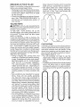
• You will find tilling much easier ifyou leave
a row untilled between
passes. Then go
back between
tilled rows There are two
/
reasons for doing this. First, wide turns
are much easier to negotiate than about-
10
A
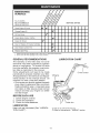
MAINTENANCE
SCHEDULE
4"7 #
FILL IN DATES
AS YOU COMPLETE
REGULAR
SERVICE
DATES
SERVICE
Check Engine Oil Level
Change Engine Oil
_1,2
Oil Pivot Points
Inspect Spark Arrester / Muffler
if
Inspect Air Screen
I_
Clean or Replace Air Cleaner Cartridge
_2
Clean Engine Cylinder Fins
t_
Replace Spark Plug
If
1 - Change more often when operating under a heavy load or in high ambient temperatures.
2 - Service more often when operating in dirty or dusty conditions.
GENERAL
RECOMMENDATIONS
LUBRiCATiON
CHART
The warranty
on this tiller does not cover
items that have been subjected to operator
abuse or negligence.
To receive full value
from the warranty, the operator must maintain tiller as instructed
in this manual.
Some adjustments
will need to be made
periodically
to properly maintain your tiller.
All adjustments
in the Service and Adjustments section of this manual should
be
checked
at least once each season.
• Once a year you should replace the spark
plug, clean or replace air filter, and check
tines and belts for wear. A new spark plug
and clean air filter assure proper air-fuel
mixture and help your engine run better
and last longer.
BEFORE
1.
2.
3.
Check
Check
Check
EACH USE
engine oil level.
tine operation.
for loose fasteners.
LUBRICATION
Keep unit well lubricated
TION CHART")
.
(See "LUBRICA-
O SAE 30 OR 10W-30MOTOR OIL
@ Refer to Maintenance "ENGINE"
11
section
_CAUTION:Disconnect
spark plug wire
before performing
any maintenance
(except
carburetor adjustment)
to prevent accidental
starting of engine.
Prevent fires! Keep the engine free of grass,
leaves, spilled oil, or fuel. Remove fuel from
tank before tipping
unit for maintenance.
Clean muffler area of all grass, dirt, and
debris.
Do not touch hot muffler or cylinder
contact may cause burns.
\
fins as
Filler
Plug
ENGINE
Oil
Drain
Plug
Level
LUBRICATION
Use only high quality detergent oil rated with
API service classification SG-SL Select the
oil's SAE viscosity grade according to your
expected temperature.
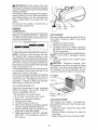
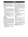
AIR CLEANER
Service air cleaner cartridge every 50 hours,
more often if engine is used in very dusty
conditions.
1. Loosen air cleaner screw.
2. Remove air cleaner cover.
SAE VISCOSITY GRADES
3.
F
-20
c -_0
0
30
-2;
TEMPERATURE
-1;
RANGE
32
40
;
ANTICIPATED
60
1'0
BEFORE
80
_0
100
_0
4;
NEXT OIL CHANGE
4. Clean bytapping
gentlyon
aflatsurface.
NOTE: If very dirty or damaged,
replace
cartridge.
5. Clean and replace cover. Tighten screw
securely.
&CAUTION:
Petroleum
solvents,
such
as kerosene,
are not to be used to clean
cartridge.
They may cause deterioration
of
the cartridge.
Do not oil cartridge.
Do not
use pressurized
airto clean or dry cartridge.
NOTE:
Although
multi-viscosity
oils (5W30, 10W-30, etc.) improve
starting in cold
weather, these multi-viscosity
oils will result in
increased oil consumption
when used above
32°F (0°C). Checkyour
engine oil level more
frequently to avoid possible engine damage
from running low on oil.
Change the oil after every 50 hours of operation or at least once a year if the tiller is not
used for 50 hours in one year.
Check the crankcase
oil level before starting
the engine and after each five (5) hours of
continuous
use. Add SAE 30 motor oil or
Air Cleaner
Cartrid(
Cover
equivalent.
Tighten
oil filler plug securely
each time you check the oil level.
TO CHANGE
ENGINE OIL
Determine
temperature
range
before oil change.
All oil must
service classification
SG-SL
• Be sure tiller
Carefully
remove air cleaner cartridge.
Be careful. Do not allow dirt or debris to
fall into carburetor.
expected
meet API
Air
Cleaner
Screw
is on level surface.
• Oil will drain more freely when warm.
• Catch oil in a suitable container.
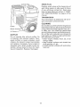
COOLING
1. Remove drain plug.
2. Tip tiller forward to drain oil.
3. After oil has drained completely,
replace
oil drain plug and tighten securely.
4. Remove oil filler plug. Be careful not to
allow dirt to enter the engine.
5. Refill engine with oil. See "FILL ENGINE
WITH OIL " in the Operation
section of
this manual.
SYSTEM
Your engine is air cooled.
For proper engine performance
and long life keep your
engine clean.
• Clean air screen
frequently
using a stiffbristled brush.
• Remove
blower housing
and clean as
necessary.
• Keep cylinder fins free of dirt and chaff.
12
SPARK PLUG
'linder Fins
Replace spark plugs at the beginning of
each tilling season or after every 50 hours
of use, whichever comes first. Spark plug
type and gap setting are shown in "PRODUCT SPECIFICATIONS"
on page 4 of this
manual.
TRANSMISSION
Your transmission
quire
lubrication
is sealed
unless
and will not re-
serviced.
CLEANING
Muffler
Do not clean your tiller when the engine and
transmission
are hot. We do not recommend
Blower Housing
using pressurized
water (garden hose, etc.)
to clean your unit unless the gasket area
around thetransmission
and the engine muffler, air filter and carburetor
are covered to
keep water out. Water in engine will shorten
the useful life of your tiller.
• Clean engine, wheels,
finish, etc. of all
foreign matter.
• Keep finished
surfaces
and wheels free
of all gasoline,
oil, etc.
• Protect painted surfaces with automotive
type wax.
Air Screen
MUFFLER
Do not operate
tiller without
muffler.
Do
not tamper
with exhaust
system.
Damaged mufflers
or spark
arresters
could
create a fire hazard.
Inspect
periodically
and replace if necessary.
If your engine is
equipped
with a spark arrester screen assembly, remove every 50 hours for cleaning and inspection.
Replace if damaged.
13
_I,,CAUTION:
Disconnect
spark plug wire
from spark plug and place wire where it
cannot come into contact with plug.
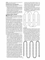
NARROWTILLING/CULTIVATING-12-3/4"
PATH
* Remove outer tines.
TILLER
TO ADJUST HANDLE HEIGHT
Factory assembly
has provided lowest handle height. Select handle height best suited
foryourtilling
conditions.
Handle heightwill
be different when tiller digs into soil.
1. If a higher
handle
height
is desired,
loosen the four nuts securing
handle
panel to engine brackets.
2. Slide handle panel to desired location.
3. Tighten the four nuts securely.
,/"r='3
NOTE: When reassembling outer tines, be
sure right tine assembly (marked "R") and
left tine assembly (marked "L') are mounted
to correct side of tine shaft.
TINE OPERATION CHECK
_I:_WARNING: Disconnect spark plug wire
from spark plug to prevent starting while
checking tine operation.
For proper tine operation, tine control lever
must be against control body and all slack
removed from inner wire of control cable
when control is in the "OFF" (up) position.
If lever and cable are loose, loosen cable
clip at lower end of cable. Pull up on cable
to remove slack, without extending spring
on end of cable, and retighten cable clip.
FINAL CHECK "OFF" POSITION
Your outer tines can be assembled
1. With tine control "OFF" (up), push down
on handle to raise tines off the ground.
2. Slowly pull recoil starter handle while
observing tines. Tines should not rotate.
3. Iftines rotate, innerwire ofcontrol cable is
too tight which is extending lower spring
and engaging tines. Loosen cable clip
and push down on cable only enough
to relieve spring tension. Tighten cable
clip.
4. Recheck in "OFF" position and adjust if
necessary.
in several
different ways to suit your tilling or cultivating needs.
_,CAUTION:
Tines are sharp. Wear gloves
or other protection
when handling
tines.
- 24" PATH
"A" in tine hubs
Clevis Pin
_
_
6
\
ARRANGEMENT
* Assemble
holes
"B" in tine shaft.
oo]
Inner Tines Only
Nuts
(Also
2 on
Left
Side
of
Tiller
TILLING
I Io
tine
Handle
Panel
NORMAL
_.
r===l
Engine Brackets
TINE
I
oil
Outer Tine
I1_1 _
to holes
\
"A" _.,
FINAL CHECK "ON" POSITION
5.
Hairpin CIi,
MID-WIDTH
TILLING
-"Inner
Tine
6.
- 22" PATH
* Assemble
holes "A" in tine hubs
"C" in tine shaft.
"C"
o/, [1 !4ll b- /°
to holes
7.
__"_
8.
14
With tine control
"ON" (held down to
handle) push down on handle to raise
tines off the ground.
Slowly pull recoil starter handle while
observing
tines.
Tines should
rotate
forward.
Iftines do not rotate, innerwire
ofcontro!
cable is too loose.
Loosen cable clip
and pull cable up to remove slack and
retighten
clip.
Recheck in "ON" position and adjust
if
necessary.
BELT REPLACEMENT
NOTE:
If "ON" position
check required
adjustment,
recheck
"OFF"
position
adjustment
to insure tines do not rotate when
control is "OFF" (up).
3.
Install new V-belt to engine pulley first
then to transmission
pulley. Be sure belt
is positioned
on inside groove of both
pulleys, inside all belt guides and rests
on idler pulley.
Body
CHECK
Tine Control
"Off" (UP)
Position
Tine Control
"On" (DOWN)
Position
TINE OPERATION
4.
See "TINE OPERATION
section of manual.
5.
Replace
CHECK"
in this
belt guard.
Belt Guide
/
Tine Control Cable_
Engine
Pulle'
Cable Clip.,,
/
\
\
\
V-Belt
Idler Pulley
\
ENGINE
Maintenance,
repair, or replacement
of the
emission control devices and systems, which
are being done at the customers
expense,
may be performed
by any non-road
engine
repair establishment
or individual.
Warranty
repairs must be performed
by an authorized
engine manufacturer's
service outlet.
TO ADJUST
CARBURETOR
TO REMOVE BELT GUARD
,
2.
3.
Transmission Pulley
Remove screws from side of belt guard.
Pull belt guard out and away from unit.
Replace belt guard by reversing
above
procedure.
Be sure slot in bottom of belt
guard is under head of tine shield bolt
and all nuts are tightened
securely.
The carbu retor has been preset at the factory
and adjustment
should not be necessary.
However,
engine
performance
can be affected by differences
in fuel, temperature,
altitude or load. If the carburetor
does need
Screw
Belt Guard
Screw
adjustment,
contact your nearest authorized
service center/department
IMPORTANT:
Never tamper with the engine
governor,
which is factory
set for proper
engine speed.
Overspeeding
the engine
above the factory high speed setting can be
dangerous.
If you thinkthe engine-governed
high speed needs adjusting,
contact
your
nearest
sears or other qualified
service
center
which
has the proper
equipment
and experience
to make any necessary
adjustments.
Screw
TO REPLACE
V=BELT
Replace V-belt if it has stretched
considerably or if it has cracks or frayed edges.
1. Belt guard must be removed
to service
belt. See "TO REMOVE BELT GUARD"
in this section of manual.
BELT REMOVAL
2. Remove V-belt from transmission pulley
first and then from engine pulley.
15
Immediately prepare your tiller for storage
at the end of the season or if the unit will
not be used for 30 days or more.
_,Warning: Never store the tiller with
gasoline in the tank inside a building where
• Use fresh fuel next season.
NOTE:
Fuel stabilizer
is an acceptable
alternative
in minimizing
the formation
of
fue! gum deposits
during
storage.
Add
stabilizer to gasoline in fuel tank or storage
container.
Always follow the mix ratio found
on stabilizer container.
Run engine at least
10 minutes after adding stabilizer
to allow
the stabilizer
to reach the carburetor.
Do
fumes may reach an open flame or spark.
Allow the engine to cool before storing in
any enclosure.
TILLER
1.
2.
3.
4.
5.
not empty the gas tank
using fuel stabilizer.
ENGINE OIL
Clean entire tiller (See "CLEANING"
in
the Maintenance
section of this manual).
Inspect and replace belts, if necessary
(See belt replacement
instructions in the
Service and Adjustments
section of this
manual).
Lubricate
as shown in the Maintenance
section of this manual.
and
carburetor
if
Drain oil (with enginewarm)
and replace with
clean oil. (See "ENGINE" inthe Maintenance
section of this manual).
CYLINDER
1.
2.
Be sure that all nuts, bolts and screws
are securely fastened.
Inspect moving
parts for damage,
breakage
and wear.
Replace if necessary.
Touch up a!l rusted or chipped
paint
surfaces;
sand lightly before painting.
3.
4.
Remove spark plug.
Pour 1 ounce (29ml) ofoilthroughspark
plug hole into cylinder.
Pull starter handle slowly several times
to distribute
oil.
Replace
with new spark
plug.
OTHER
ENGINE
• Do not store
to another.
FUEL SYSTEM
gasoline
from
one season
• Replace
your gasoline
can if your can
starts to rust.
Rust and/or dirt in your
gasoline will cause problems.
• If possible,
store your unit indoors and
cover it to give protection
from dust and
dirt.
IMPORTANT:
It is important
to prevent
gum deposits
from forming
in essential
fuel system parts such as the carburetor,
fuel filter, fuel hose, or tank during storage.
Also, alcohol blended fuels (called gasohol
or using ethanol or methanol)
can attract
moisture
which
leads to separation
and
formation of acids during storage. Acidic gas
can damage the fuel system of an engine
while in storage.
• Empty the fuel tank by starting the engine
and letting it run until the fuel lines and
carburetor
are empty.
• Never use engine or carburetor
cleaner
products
in the fuel tank or permanent
damage may occur.
• Cover your unit with a suitable protective
cover that does not retain moisture.
Do
not use plastic.
Plastic cannot
breathe
which allows condensation
to form and
will cause your unit to rust.
IMPORTANT:
Never cover tiller while engine
and exhaust areas are still warm.
16
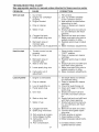
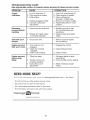
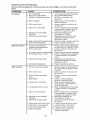
TROUBLESHOOTING
See appropriate
section in manual
PROBLEM
Will not start
unless directed to Sears service center
CAUSE
CORRECTION
1. Out of fuel.
2.
3.
Engine not "CHOKED"
properly.
Engine flooded.
4.
Dirty air cleaner.
5.
Water
.
7.
8.
9.
Hard to start
CHART:
in fuel.
Clogged fuel tank.
Loose spark plug wire.
Bad spark plug or
improper gap.
Carburetor
out of adjustment.
1. Throttle
2.
3.
control
properly.
Dirty air
not set
cleaner.
1. Fill fuel tank.
2. See "TO START
in the Operation
section.
3. Wait several minutes before
attempting
to start.
4. Clean or replace air cleaner
cartridge.
5. Empty fuel tank and carburetor, and refill tank with fresh
gasoline.
6. Remove fuel tank and clean.
7. Make sure spark plug wire is
seated properly on plug.
8. Replace spark plug or adjust
gap.
9. Make necessary
adjustments.
1. Place throttle
2.
3.
4.
Bad spark plug or
improper gap.
Stale or dirty fuel.
5.
Loose
5.
6.
Carburetor
spark
4.
plug wire.
out of
ENGINE"
6.
control
in
"FAST" position.
Clean or replace air cleaner
cartridge.
Replace spark plug or adjust
gap.
Empty fuel tank and refill tank
with fresh clean gasoline.
Make sure spark plug wire is
seated properly on plug.
Make necessary
adjustments.
adjustment.
Loss of power
1.
Engine
is overloaded.
2.
Dirty air cleaner.
3.
4.
Low oil level/dirty oil.
Faulty spark plug.
5.
Oil in fuel.
6.
Stale or dirty fuel.
7.
Water
8.
9.
Clogged
fuel tank.
Spark plug wire loose.
1. Set depth stake and wheels
for shallower
tilling.
2. Clean or replace air cleaner
cartridge.
3. Check oil level/change
oil.
4. Clean and regap or change
spark plug.
5. Empty and clean fuel tank
and refill, and clean carburetor.
10. Dirty engine air screen.
11. Dirty/clogged
muffler.
12. Carburetor
out of
6. Empty fuel tank and refill tank
with fresh clean gasoline
7. Empty fuel tank and carburetor, and refill tank with fresh
gasoline.
8. Remove fuel tank and clean.
9. Connect and tighten spark
plug wire.
10.Clean engine air screen.
11 .Clean/replace
muffler.
12. Make necessary adjust ments.
adjustment.
13. Poor compression.
13. Contact
in fuel.
qualified
17
a Sears or other
service
center.
TROUBLESHOOTING CHART:
See appropriate section in manual unless directed to Sears service center
PROBLEM
CAUSE
Engine
overheats
Excessive
bounce/difficult
handling
CORRECTION
1.
2.
3.
Low oil level/dirty
oil.
Dirty engine air screen.
Dirty engine.
4.
5.
Partially plugged
muffler.
Improper
carburetor
adjustment.
1. Ground
too dry and hard.
2. Wheels and depth stake
incorrectly adjusted.
Soil balls up or
clumps
1. Ground
Engine runs but
tiller won't move
1. Tine control
2.
3.
Engine runs but
labors when
tilling
too wet.
is not
to richer
1. Moisten ground or wait
for more favorable
soil
conditions.
2. Adjust wheels and depth
stake.
1. Engage
2.
Throttle
3.
properly
adjusted.
Carburetor
out of
tine control.
2. Inspect/adjust
3. Inspect
too deep.
control
5. Adjust carburetor
position.
1. Wait for more favorable
soil conditions.
engaged.
V-belt not correctly
adjusted.
V-belt is off pulley(s).
1. Tilling
1. Check oil level/change
oil.
2. Clean engine air screen.
3. Clean cylinder fins,
airscreen,
muffler area.
4. Remove and clean muffler.
V-belt.
V-belt.
1. Set depth stake for shallower tilling.
2. Check throttle control setting.
not
3. Make necessary
ments.
adjustment.
adjust-
NEED MORE HELP?
Yotf_[
find
the
answer
a_/d more
oil. managemyhemeocem
o Find this and aLLyour other product manuals online.
o Get answers from our team of home experts.
o Get a personalized maintenance
o Find information
plan for your home.
and tools to heLp with home projects.
bro_Jght to you by Sears
'4
18
-
for
free!
Garantia ........................................................
19
Mantenimiento
Reglas de Seguridad .............................. 19-20
Especificaciones del producto .................... 21
Montaje/Pre Operacion ........................... 22-23
Operaci6n ...............................................
24-27
Programa De Mantenimiento ....................... 28
Garantia Completa
..............................................
28-30
Servicio y Ajustes ..........................................
31-32
AImacenamiento ................................................
33
Identificaci6n de Problemas ......................... 34-35
Partes del Reparaci6n ................................... 36-47
Vea el manual Ingles del duefio ...Trasera Portada
para equipos tractores
Craftsman
Professional
POR DOS ANOS desde la fecha de compra, todas las partes no sustituibles
de este equipo tractor est&n
garantizadas
contra cualquier defecto de material o mano de obra. Una parte no sustituible defectuosa
recibir& reparaci6n o reemplazo gratuito en casa si la reparaci6n es imposible.
POR CINCO AKIOS desde la fecha de compra, el bastidor y el eje delantero de este equipo tractor est&n
garantizados
contra cualquier defecto de material o mano de obra. Un bastidor o eje delantero defectuoso
recibir& reparaci6n o reemplazo gratuito en casa si la reparaci6n es imposible.
Toda la cobertura de garantia anterior se aplica Onicamente pot un afio a partir de la fecha de compra si
este equipo tractor alguna vez se utiliza con fines comerciales
o de alquiler.
DURANTE 90 DiAS desde la fecha de compra, la bateria (una parte sustituible) de este equipo tractor est&
garantizada
contra cualquier defecto de material o mano de obra (nuestra prueba comprueba
que no
contendr& carga). Una bateria defectuosa
recibir& un reemplazo gratuito en casa.
GARANTiA
LIMITADA
DE POR VIDA ADIOIONAL
en el EJE DELANTERO
DE HIERRO COLADO
(si esta provisto)
DURANTE EL TIEMPO EN QUE SE USE pot el propietario
original despu_s del quinto afio a partir de la
fecha de compra, el eje delantero de hierro colado (si est& provisto) de este equipo tractos est& garantizado
contra cualquier defecto de material o mano de obra. Con el comprobante
de compra, un eje delantero de
hierro colado recibir& un reemplazo gratuito en casa.
SERVIClO DE GARANTiA
Para conocer
los detalles
de la cobertura
de
Reparaciones
necesarias
por
abuso
del
garantia para obtener una reparaci6n
o reemplazo
operador
incluso, pero sin limitarse a, dafios
gratuito,
Ilame al 1-800-659-5917
6 visite el sitio
causados
pot remolcar objetos
que superen
web: www. craftsman.com
la capacidad
del equipo tractor, chocar contra
objetos que doblen el bastidor, el ensamble del
En todos los casos anteriores, si el reemplazo es
eje o el cigQefial o sobrepasar
la velocidad
del
imposible,
el equipo tractor set& sustituido
sin
motor.
cargo con el mismo modelo o uno equivalente.
Reparaciones
necesarias
pot negligencia
del
operador,
incluso
(pero sin limitarse
a ello)
dafios el6ctricos
y mec&nicos
causados
pot
el almacenamiento
incorrecto,
pot no usar el
grado y la cantidad correctos de aceite de motor,
pot no mantener
del muelle libre de residuos
inflamables o pot no mantener el equipo tractor
de acuerdo con las instrucciones
que contiene
el manual del operador.
Limpieza o reparaciones
del motor (sistema de
combustible)
cuando se determina que se us6
combustible
contaminado
y oxidado (sarro). En
general, el combustible
debe usarse dentro de
los 30 dias posteriores a su compra.
Deterioro y desgaste normal de los acabados
exteriores o sustituci6n de r6tulos de productos.
Esta garantia
cubre ONICAMENTE
defectos
de
material y mano de obra. La cobertura de garantia
NO incluye:
Partes sustituibles
(excepto la bateria) que se
puedan desgastar pot el uso normal dentro del
periodo de garantia incluso, pero sin limitarse a,
cuchillas,
bujias, filtros de aire, correas y filtros
de aceite.
Servicios de mantenimiento
de aceite o afinaciones.
est&ndar,
cambios
Reemplazo
o reparaci6n
de neum&ticos
pot
pinchazos causados pot objetos externos como
clavos, espinas, tocones o vidrios.
Reemplazo
o reparaci6n
de neum&ticos
o
ruedas pot desgaste normal, accidentes
o pot
operaci6n o mantenimiento
incorrectos.
Esta garantia le otorga derechos
varian de un estado a otto.
Sears Brands
legales
Management
especificos,
y usted tambi6n
Corporation,
Hoffman
puede
tenet
Estates,
otros
derechos
que
IL 60179
IMPORTANTE:
Esta Maquina
cortadora
es capaz de amputar
las manosy
los pies y de lanzar
objetos, si no se observan
las instrucciones
de seguridad
siguientes
se pueden producir
lesiones
graves
o la muerte,
parar
ENTR ENAM I ENTO
•
Lea el Manual del Duefio cuidadosamente.
Familiaricese
completamente
con los controlesy
con el uso adecuado
del equipo. Sepa como
la unidad
y desenganchar
los controles
r&pidamente.
19
• Nunca permita que los nifios operen el equipo.
Nunca
permita
que los adultos
operen
el
equipo sin los conocimientos
adecuados.
• Mantenga el &rea de operacion despejada de
personas, especialmente
nifios pequefios y
animales domesticos.
• Nunca opere la cultivadora sin las protecciones, y las planchas adecuadas y sin los demas
dispositivos de seguridad en su lugar.
• Mantenga a los nifios y a los animales domesticos alejados.
• No sobrecargue la capacidad de la m&quina,
tratando de cultivar a mucha profundidad, muy
r&pido.
• Nunca opere la maquina a altas velocidades
en superficies resbalosas. Mire hacia atras y
tenga cuidado cuando retroceda.
• Nunca permita la presencia de espectadores
cerca de la unidad.
• Use solamente accesorios y aditamentos para
la cultivadora aprobados pot el fabricante.
• Nunca opere la cultivadora sin buena visibilidad o luz.
• Tenga cuidado al cultivar en terreno duro.
Los brazos pueden quedarse agarrados en el
suelo e impulsar a la cultivadora hacia adelante. Si esto sucede, suelte los mangos y no
restrinja la maquina.
PREPARACION
• Inspeccione cuidadosamente el &rea en donde
se va usar el equipo y remueva los objetos
extrafios.
• Desenganche todos los embragues y cambie
a neutro antes de hacer arrancar el motor.
• No opere el equipo sin usar ropa exterior adecuada. Use zapatos que mejoren el equilibrio
en superficies resbalosas.
• Maneje el combustible con cuidado pues es
muy inflamable.
• Use un envase de combustible aprobado.
• Nunca afiada combustible
a un motor en
funcionamiento
o caliente.
• Llene el estanque de combustible afuera con
mucho cuidado. Nunca Ilene el estanque de
combustible en un recinto cerrado.
• Vuelva a colocar la tapa del dep6sito de gasolina en forma segura y limpie el combustible
derramado antes de volver a arrancar.
• Use cordones de extensi6n y receptaculos,
seg0n las especificaciones del fabricante, para
todas las unidades con motores de impulsi6n
o con motores de arranque electrico.
• Nunca trate de hacer ning0n ajuste mientras
que el motor este funcionando (excepto en los
casos especificamente recomendados pot el
fabricante).
OPERAClON
• No ponga ni las manos ni los pies cerca o
debajo de las piezas rotatorias.
• Tenga mucho cuidado cuando opere o cruce
entradas para automoviles de ripio, senderos
o caminos. Este alerta en Io que se refiere a
los peligros escondidos o al trafico. No Ileve
pasajeros.
• Despues de pegarle a un objeto extrafio,
pare el motor, remueva el alambre de la bujia,
inspeccione la cultivadora cuidadosamente,
para verificar si hay daSos, y repare el dafio
antes de volver a arrancar y operar la cultivadora.
• Tenga cuidado para evitar resbalarse o caerse.
• Si la unidad empieza a vibrar anormalmente,
pare el motor y revisela inmediatamente para
verificar la causa. La vibracion normalmente
es un aviso de problemas.
• Pare el motor cuando abandone la posici6n
de operaci6n.
• Tome todas las precauciones posibles cuando
deje la m&quina desatendida. Desenganche
los brazos, cambie a neutro y pare el motor.
• Antes de limpiar, reparar e inspeccionar,
apague el motor y asegQrese que todas
las partes en movimiento se han detenido.
Desconecte el alambre de la bujia, y mantengalo alejado de esta para evitar el arranque
pot accidente. Desconecte el cordon en los
motores electricos.
• No haga funcionar el motor en recintos cerrados; los gases de escape son peligrosos.
MANTENIMI ENTO Y ALMAC ENAMIENTO
• Mantenga los accesorios y aditamentos de
la m&quina en buenas condiciones
para el
funcionamiento.
• Revise las clavijas de seguro, los pernos de
montaje del motor y otros pernos, a intervalos
frecuentes, para verificar si estan apretados en
forma segura y asegurarse que el equipo este
en buenas condiciones de funcionamiento.
• Nunca guarde la maquina con combustible
en el estanque de combustible
dentro de
un edificio en donde hay fuentes de ignicion
presentes, tales como calentadores de agua
o del ambiente, secadoras de ropa u otros
artefactos parecidos. Permita que se enfrie
el motor antes de guardarlo en algOn lugar
cerrado.
• Siempre refierase a las instrucciones en la guia
del operador para vet los detalles de importancia si la cultivadora va a set guardada pot
un periodo de tiempo largo.
,_Busque
este simbolo que sehala las precauclones de seguridad
de importancia.
Quiere
deciriiiATENCION!!!
iiiESTE ALERTO!!! SU
SEGURIDAD ESTA COMPROMETIDA.
_PREOAUOI6N:
Siempre desconecte el alambre de la bujia y p6ngalo donde no pueda entrar
en contacto con la bujia, para evitar el arranque
pot accidente, durante la preparaci6n, el transporte, el ajuste o cuando se hacen reparaciones.
_ADVERTENOIA:
El tubo de escape del motor,
algunos de sus constituyentes y algunos componentes del vehiculo contienen o desprenden
productos quimicos conocidos en el Estado de
California como causa de c&ncer y defectos al
nacimiento u otros dafios reproductivos.
20
ESPECIFICACIONES
DEL PRODUCTO
Capacidad de
Gasolina:
2.9 Cuartos
Sin plomo, Regular
Aceite (API:SG-SL):
(Oapacidad: 20 oz.)
SAE 30 (Sobre 32°F/0°O)
SAE 5W-30 (Debajo 32°F/0°O)
Bujia :
(Abertura:0,030")
Ohampion
RC12YC
ACUERDOS
DE PROTECClON
PARA
LA REPARAClON
Congratulaciones
pot su buena compra. Su
nuevo producto Craftsman®
est& disefiado y
fabricado para funcionar de modo fiable pot
muchos afios. Pero como todos los productos,
puede necesitar alguna reparaci6n de tanto en
tanto. En este caso tenet un Acuerdo de Protecci6n para la Reparaci6n puede hacerles ahorrar
dinero y fastidios.
Compre ahora un Acuerdo de Proteccion para
la Reparaci6n y protegese de molestias y gastos
inesperados.
Un Acuerdo incluye los puntos siguientes:
• Servicio experto de nuestros 12.000 especialistas profesionales en la reparacion.
• Servicio ilimitado sin cargo alguno para
las partes y la mano de obra sobre todas las
reparaciones garantizadas.
• Sustituci6n
del producto si su producto
garantizado no puede set arreglado.
• Descuento del 10% sobre el precio corriente
del servicio y de las partes relativas al servicio
no cubiertas pot el acuerdo; tambien el 10%
menos sobre el precio corriente de un control
de mantenimiento preventivo.
• Ayuda r_pida pot tel_fono - soporte telefonico por parte de un tecnico Sears sobre
productos que requieren un arreglo en casa, y
adem&s una programaci6n sobre los arreglos
m&s convenientes.
Cuando se ha comprado el Acuerdo, basta con
una Ilamada telefonica para programar el servicio. Puede Ilamar cuando quiera, dia y noche o
fijar en linea una cita para obtener el servicio.
Sears tiene mas de 12.000 especialistas profesionales en la reparacion, que tienen acceso a mas
de 4.5 millones de partes y accesorios de calidad.
Este es el tipo de profesionalidad
con que
puede contar para ayudar a alargar la vida del
producto que acaba de comprar, por muchos
afios, iCompre hoy su Acuerdo de Protecci6n
para la Reparaci6n!
FELlClTACiONES
por la compra de su Cultivadora Sears. Ha sido disefiada, planificada y
fabricada para darle la mejor confiabilidad y el
mejor rendimiento posible.
En el caso de que se encuentre con cualquier
problema que no pueda solucionar f&cilmente,
haga el favor de ponerse en contacto con su
centro de servicio cualificado. Sears cuenta con
tecnicos bien capacitados y competentes
con
herramientas adecuadas para darle servicio o
para reparar su unidad.
Haga el favor de leer y de guardar este manual.
Estas instrucciones le permitir&n montar y mantenet su cultivadora en forma adecuada. Siempre
observe las "REGLAS DE SEGURIDAD."
RESPONSABILIDADES
DEL CLIENTE
• Lea y observe las reglas de seguridad.
• Siga un programa regular de mantenimiento,
cuidado y uso de su cultivadora.
• Siga las instrucciones descritas en las secciones "Mantenimiento"
y "Almacenamiento"
de este Manual del Duefio.
_ADVERTENClA:
Esta unidad viene equipada con un motor de combusti6n interno y no
se debe usar sobre, o cerca, de un terreno no
desarrollado cubierto de bosques, de arbustos
o de cesped, a menos que el sistema de escape
del motor venga equipado con un amortiguador
de chispas que cumpla con las leyes locales o
estatales (si existen). Si se usa un amortiguador
de chispas, el operador debe mantenerlo en
condiciones de trabajo eficientes.
En el estado de California, la ley exige Io anterior
(Secci6n 4442 del "California Public Resources
Code" [Decreto de Recursos POblicos de California]). Otros estados pueden contar con otras
leyes parecidas. Las leyes federales se aplican
en las tierras federales.
Su centro de Servicio
m&s cercano tiene disponible amortiguadores
de chispas para el silenciador. (Vea la seccion
de Partes de Repuesto en el manual Ingles del
duefio.)
Se aplican algunas limitaciones y exclusiones.
Para conocer los precios y tener m_s infor=
maci6n, Ilarne al 1=800=827=6655.
SERVlClO
DE INSTALACION
SEARS
Para la instalaci6n profesional Sears de aparatos
de casa, puertas de garaje, calentadores de agua
y otros importantes articulos para la casa, en
U.S.A Ilamar a I=800=4=IVIY=HOME®
21
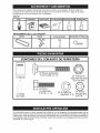
Estos accesorios estaban disponibles cuando se produjo la cultivadora. Tambien est_tn disponibles en la mayoria de las tiendas de Sears yen los centros de servicio. Algunos de estos
accesorios tal vez no se apliquen a su cultivadora.
MOTOR
BUJJA
SILENCIADOR
MANTENIMIENTO
FILTRO
DE AIRE
LATA DE GASOLINA
ACEITE DEL MOTOR
ESTABILIZADOR
DE LA CULTIVADORA
CORREA
BRAZOS
CLAVIJA
DE SEGURO
ABRAZADERA
DE HORQUILLA
0
CONTENIDO
(
DEL CONJUNTO
DE FERRETERIA
O
(2) Pernos portadores
5/16-18 UNC x 2-1/2
(2) Tuercas de
seguridad de brida
5/16-18 UNC
(1) Manual
(1) Aceite
del motor
(2) Perno
hexagonales
5/16-18 x 1-1/4
Q
(2) Arandela
seguridad
de
5/16
(2) l-uerca
hexag0nales
5/16-18
Su cultivadora nueva ha sido montada en la fabrica, con la excepcion de aquellas partes que se
dejaron sin montar pot razones de env[o. Para asegurarse que la cultivadora operara en forma segura
y adecuada, todas las partes y los art[culos de ferreter[a que monte tienen que estar apretados en
forma segura. Use las herramientas correctas, segQn sea necesario, para asegurarse de que queden
apretadas en forma segura.
22
HERRAMIENTAS
NECESARIAS
PARA
EL MONTAJE
Se le facilitar& el montaje si cuenta con un juego
de Ilaves de tubo. Se han enumerado los tama_os esta.ndar de las Ilaves.
(1) Cuchillo para todo uso
(2) Llave de 1/2"
POSiClON DEL OPERADOR
Cuando en este manual se mencionan los t@minos "lado derecho" o "lado izquierdo" se refiere
a cuando usted se encuentra en la posici6n de
operaci6n (parado/a detras de los mangos de
la cultivadora).
Parte Delantera
2.
El mango puede ser montado en la posicion
alta o baja. Lentamente, levante el conjunto
del mango hacia arriba y alihe los agujeros
del mango con el agujero y ranura del panel
del mango.
3. Afloje el montaje de la quincalleria como
mostrado. AsegQrese que el perno hexagonal m_.s corto (1" de largo) este montado en
el agujero inferior del mango.
Repita este
procedimiento en el otto lado. Apriete toda
la quincalleria con seguridad.
AViSO: Los cables no deben tocar el silenciador.
4. Corte las ligaduras del cable que aseguran
la cultivadora al rodillo y remueva la cultivadora del rodillo.
5. Quitar el tornillo de fijacion del pilote de
profundidad para girar y remover el tornillo.
INSTALACION
DEL CONJUNTO
ESTACA DE PROFUNDIDAD
Lado
Izquierdo
1. Afloje la tuercas "A".
2. Inserte el soporte de la estaca entre las mitades del puntal del motor, con el resorte de la
estaca hacia abajo.
,
Aperen el soporte de la estaca en los puntales del motor con los pernos hexagonales,
las arandelas de seguridad y las tuercas.
Apri@elos en forma segura. Tambien apriete
las tuercas "A".
,
La estaca de profundidad se tiene que mover
libremente. Si no Io hace, suelte el perno de
soporte.
Lado
Derecho
Posicion del operador
DESEMPAQUE
DE LA CAJA DE CARTON
APRECAUCION:Tenga
cuidado con las grapas
expuestas cuando maneje o deseche los materiales de la caja de carton.
IMPORTANTE:
Cuando desempaque y monte
la cultivadora,
tenga cuidado de no estirar o
enredar los cables.
1. Corte las ligaduras del cable que aseguran
los mangos.
Panel del mango
z--
_..
Mitades del puntal del motor
Tuerca "A"
N
//_S
{_/7////
I °p°rte de _arefStac_addc_
/
lsTU;roCtaede
//_//_
Mango de la
cultivadora
Arandela
seguridad
Mangos de la
cultivadora
DE LA
Pernos hexagonales, arandelas de
seguridad y tuercas hexagonales
Pemo
hexagonales
5/16-18 x 1-1/4"
Pernos del
panel del
mango
23
ALTURA
DEL MANGO
• Se puede ajustar la altura del mango en la
mejor forma que le acomode al operador.
(Vea "ALTU RA DEL MANGO" en la seccion de
Servicio y Ajustes de este manual.)
ANCHO
DEL LABRADO
• Se puede ajustar el ancho del labrado para
manejar mejor sus condici6nes de labraci6n (vea
'ARREGLO DE LOS BRAZOS" en la secci6n de
Servicio y Ajustes de este manual).
OPERAClON
DE LOS BRAZOS
• Revise la operaci6n de los brazos antes del
primer uso (vea "REVISION DE LA OPERACION DE LOS BRAZOS" en la secci6n de
Servicio y Ajustes de este manual).
Estossimbolospuedenaparesersobresu cultivadoraenla literatureproporcionadaconel producto,aprenday comprendasussignificados.
CONOZCA
SU CULTIVADORA
Compare lae ilustraciones con su cultivadora para familiarizarse
con la ubicaci6n
diversos controles y ajustes. Guarde este manual para futura referencia.
de Ice
LEA ESTE MANUAL DEL DUENO Y LAS REGLAS DE SEGURIDAD ANTES DE OPERAR SU CULTIVADORA
MARCHA
RETEN
LABOREO
MARCHA
NEUTRO
HACIA
Control de los brazos
marcha hacia adelante
REVES
ATTENCION
ADVERTENCIA
O
MOTOR
ENCENDIDO
MOTOR
R,_,PIDO
APAGADO
LENTO
ESTRANGU
LACION
COM-
I
O
ACEITE
BUSTIBLE
L
"_
Control de la
alaci6n
Estaca de
_\__
Control de la
J
profundidad
Defensas de
Mango del arrancador
de culateo
_
los brazo
Brazos
Las cultivadoras de Sears cumplen con los est&ndares de seguridad del
American National Standard Institute (Instituto Nacional de Estandares Americano).
CONTROL DE LA ACELERACION - Controla
la velocidad del motor.
CONTROL DE LA ESTRANGULAOi6N=
UseIo cuando se hace arrancar un motor frio.
MANGO DEL ARRANOADOR
DE CULATEO
- Se usa para hacer arrancar el motor.
CONTROL DE LOS BRAZOS MARCHA HA=
CiA ADELANTE = Engancha los brazos en la
direccion de marcha hacia adelante.
ESTACA DE PROFUNDIDAD = Controla la
velocidad de la marcha hacia adelante y la
profundidad a la cual excavar& la cultivadora.
24
La operaci6n de cualquier cultivadora puede hacer que salten objetos extrahos dentro
de sus ojos, Io que puede producir dahos graves en estos. Siempre use anteojos de
seguridad o protecciones para los ojos antes de hacer arrancar su cultivadora o mientras
este labrando con efla. Recomendamos el uso de la mascara de seguridad de visi6n
ampfia, para uso sobre los espejuelos o anteojos de seguridad est_tndar.
COMO USAR SU CULTIVADORA
RUEDAS
Sepa como operar todos los controles antes de
Ajuste las ruedas removiendo
la abrazadera
de horquilla y la clavija de horquilla. Cambie la
agregar combustible y aceite o antes de tratar
posicion de la rueda. Vuelva a colocar la abrazade hacer arrancar el motor.
dera
de horquilla y la clavija de horquilla.
PARADA
• Para el labrado normal, ajuste las ruedas en el
BRAZOS
segundo o tercer agujero a partir de la parte
• Suelte el control de los brazos para parar el
superior.
movimiento.
MOTOR
Abrazadera de
horquilla y clavija
• Mueva el control de la aceleraci6n a la posici6n
de horuilla
de "PARADA" (STOP).
AVlSO: Nunca use la estrangulaci6n para
parar el motor.
SEGURIDAD
Control de los
brazos en la
posici6n de
"Apagedo" (Arriba)
Control de la
en la posici6n
de "Encendido"
(Abajo)
Control de la estrangulaci6n
de
profundidad
de la
estaca
Control de la
aceleraci6n
Ruedas
PARA
OPERACION
DE LOS BRAZOS
• Apriete el control de los brazos contrael mango.
LABRADO
La velocidad y la profundidad del labrado son
reguladas por medio de la posici6n de la estaca
de profundidad y por la altura de la rueda. La estaca de profundidad siempre tiene que estar por
debajo de las ruedas para excavar. Sirve de freno
para retardar el movimiento de marcha hacia
adelante de la cultivadora, para permitir que los
brazos penetren en el suelo. Tambien, mientras
m&s se baje la estaca de profundidad dentro del
suelo, mas profunda sera la excavaci6n realizada
con los brazos.
ESTACA
DE PROFUNDIDAD
Ajuste la estaca de profundidad removiendo la
abrazadera de horquilla y la clavija de horquilla.
Cambie la estaca de profundidad a la posici6n
deseada. Vuelva a colocar la clavija de horquilla
y la abrazadera de horquifla.
• Para el labrado normal, ajuste la estaca de
profundidad en el segundo o tercer agujero a
partir de la parte superior.
25
EL TRANSPORTE
_PRECAUCKSN:
Antes de levantarla o transportarla, permita que el motor de la cultivadora y
el silenciador se enfrien. Desconecte el alambre
de la bujia. Drene la gasolina del estanque de
combustible.
EN EL JARDiN
1. Incline la estaca de profundidad hacia adelante, hasta que quede sujeta con el resorte
de la estaca.
2. Empuje los mangos de la cultivadora hacia
abajo, levantando los brazos por encima del
suelo.
3. Tire o empuje la cultivadora a la ubicaci6n
deseada.
EN
1.
2.
3.
LA ClUDAD
Desconecte el alambre de la bujia.
Drene el estanque de combustible.
Transp6rtela en la posici6n derecha hacia
arriba para evitar la fuga del aceite.
ANTES DE HACER ARRANCAR
EL
MOTOR
IMPORTANTE:
Tenga mucho cuidado de no
permitir que entre mugre al motor cua do revise o anada aceiteo combustible.
Use aceite
y combustible limpios y gu&rdelos en envases
aprobados, limpios y con tapa. Use embudos
para relleno limpios.
RELLENO DEL ACEITE DEL MOTOR
1. Remueva la etiqueta del motor.
2. Con el motor nivelado, remueva el tapon del
dep6sito de relleno del aceite del motor.
3. Llene el motor con aceite hasta el punto
de derramarse.
Para verificar la capacidad
aproximada vea "ESPECIFICACIONES
DEL
PRODUCTO" de este manual.
4. Inclinela cultivadorahaciaatrasensus rue- PARA HACER ARRANCAR EL MOTOR
dasy luegovuelvaa nivelarla.
,_PRECAUCI6N:
Mantenga la barra de control
5. Conelmotornivelado,
vuelvaa Ilenarlohasta de la impulsi6n en la posici6n "DESENGANCHAel punto de derramarse,si es necesario. DO" cuando haga arrancar el motor.
Vuelvaa colocarel tapondel depositode Cuando intente arrancar el motor por la primera
rellenode aceite.
o si al motor se le ha acabado la gasolina,
= Parala operacionen climafrio,debecambi- vez
ser&
necesario que estire varias veces del mango
arseel aceiteparafacilitarel arranque(veala
"TABLADEVlSCOSIDAD
DELACEITE"en la arrancador de culateo para desplazar la gasolina
seccionde Mantenimiento
enestemanual). del estanque al motor.
= Paracambiarelaceitedelmotor,vealasecci6n 1. AsegOrese que el alambre de la bujia este
conectado en forma adecuada.
de Mantenimiento
en estemanual.
2.
_.._
Niveldel.........
aceite
deposito
derelleno
aceite
Tap6n
de
_-"_
AGREGUEGASOLINA
= Llene el estanque de combustible. Llene
hastala parteinferiordelcuellode rellenodel
estanquedegasolina.NoIoIlenedemasiado.
Usegasolinaregular,sin plomo,nuevay limpiaconel minimode 87octanos. (Elusode
gasolinacon plomoaumentaralosdep6sitos
de 6xidode plomoy carbonoyse reducirala
duraci6nde la valvula). Nomezcleel aceite
con la gasolina. Paraasegurarquela gasolina utilizadaseafresca compreestanques
los cualespuedanset utilizadosdurantelos
primeros30dias.
Ponga el control de la aceleraci6n
en la
posici6n de "RAPIDO" (FAST).
3. Con el motor completamente en la posici6n
de estrangulaci6n "CHOKE. Agarre el mango
del arrancador de culateo con una mano y
el mango de la cultivadora con la otra mano.
Tire el cordon hacia afuera, lentamente, hasta
que el motor Ilegue al comienzo del ciclo de
la compresi6n (el cord6n se sentira un poco
mas duro en este momento).
4. Tire el mango del arrancador de culateo
rapidamente. No permita que el mango del
arrancador se devuelva abruptamente
en
contra del arrancador.
Vuelva a repetir en
la posici6n de semiestrangulaci6n
si Io es
necesario.
AViSO: Si los fuegos del motor se encienden
pero no arranca, mueva el control della estrangulaci6n a la posici6n de semiestrangulaci6n.
Tire del mando arrancador de culateo hasta que
el motor arranque.
5. Cuando arranque
el motor, lentamente,
mueva el control de la estrangulaci6n a la
posici6n de "FUNCIONAMIENTO"
(RUN) a
medida que se calienta el motor.
AVlSO: Un motor caliente requiere menos estrangulaci6n para empezar.
6. Mueva el control de la aceleraci6n
a la
posici6n de funcionamiento
deseada.
7. Permita que se caliente el motor por unos cuantos minutos antes de enganchar los brazos.
AVlSO: A mucha altura (sobre 3000 pies) o en
climas frios (debajo de 32 ° F [0° C]) puede que la
mezcla del combustible del carburador necesite
ajuste, para obtener el mejor resultado del motor.
Vea "PARA AJUSTAR EL CARBURADOR" en la
secci6n de Servicio y Ajustes de este manual.
_I_PREOAUOi6N:
Llene el estanque de combustible hasta dentro de 1/2 pulgada de la parte
superior para evitar los derrames y para permitir
que se expanda el combustible. Si pot casualidad
se derrama la gasolina, aleje la ma.quina del a.rea
del derrame. Evite crear cualquiera fuente de
ignici6n hasta que se hayan desaparecido los
gases de la gasolina.
Limpie el aceite o el combustible derramado. No
almacene, derrame o use gasolina cerca de una
llama expuesta.
IMPORTANTE: Cuando se opere en temperaturas pot debajo de 32°F (0°C) use gasolina de
invierno limpia y nueva para auedar a asegurar
un buen arra,nque en clima frio.
PREOAUOION:
Combustibles
mezclados con
alcohol (conocidos como gasohol, o el uso de
etanol o metanol) pueden atraer la humedad,
la que conduce a la separaci6n y formaci6n de
a.cidos durante el almacenamiento.
La gasolina
acidica puede dafiar el sistema del combustible
de un motor durante el almacenamiento.
Para
evitar los problemas con el motor, se debe vaciar
el sistema de combustible antes de guardarlo pot
un periodo de 30 dias o mas. Vac[e el estanque
de combustible, haga arrancar el motor y hagalo
funcionar hasta que las lineas del combustible
de la
y el carburador
queden vacios. La pr6xima
estrangulaci6n
temporada use combustible nuevo. Vea las Instrucciones para el AImacenamiento
para mas
Control de la
informaci6n. Nunca use productos de limpieza
para el motor o para el carburador en el estanque
Mango del
del combustible pues se pueden producir dafios
permanentes.
26de culateo
Bujia
AVlSO: Si el motor no arranca, vea la guia de
identificaci6n de problemas.
RODAJE
vuelva de nuevo entre las filas de cultivo. Hay
dos razones para hacer esto. Primero, las
vueltas amplias se pueden realizar con m&s
facilidad que las cerradas. Segundo, la cultivadora no estara empujandose a si misma y
a usted hacia la proxima hilera.
Ajuste la estaca de profundidad y la altura de
la rueda para labrado poco profundo cuando
este trabajando en suelo o terreno herboso
dem&siado duro. Luego atraviese los primeros
cortes a la profundidad normal.
DE SU CULTIVADORA
Use su(s) correa(s), las poleas y el control de los
brazos antes de empezar a labrar.
• Haga arrancar el motor, saque los brazos fuera
del suelo presionando los mangos hacia abajo
y enganche el control de los brazos para hacer
arrancar la rotacion de los brazos. Permita que
los brazos roten pot cinco minutos.
• Revise la operacion de los brazos y ajOstelos,
si es necesario. Vea "REVISION DE LA OPERACION DE LOS BRAZOS" en la seccion de
Servicio y Ajustes de este manual.
CONSEJOS
PARA LABRAR
_k, PRECAUCI6N:
Antes de acostumbrarse
a
manejar su cultivadora, empiece el uso de esta
en el terreno con la aceleraci6n en la posicion
de "lento" (SLOW).
Para ayudarle a la cultivadora a moverse hacia
adelante, levante los mangos un poco (levantando en esta forma la estaca de profundidad fuera
del suelo). Para hacer que la cultivadora ande
m&s lento presione los mangos hacia abajo.
Si est& forzandola o si la cultivadora esta vibrando, quiere decir que las ruedas y la estaca
de profundidad
no estan ajustadas en forma
adecuada para el terreno que se esta labrando.
El ajuste adecuado de las ruedas y de la estaca
de profundidad se Iogra al probarlas en acci6n y
depende de las condiciones del suelo. (Mientras
mas duro o mas mojado este el suelo, menor
es la velocidad necesaria del motor y de los
brazos. La cultivadora va a cotter y saltar sobre
el terreno si se usa en estas malas condiciones
a una velocidad rapida.)
Si la cuWvadora est& bien ajustada, excavara con
poco esfuerzo pot parte del operador.
• El labrar quiere decir el excavar, dar vuelta y
romper el suelo duro antes de plantar. El suelo
suelto y blando permite el desarrollo de las
raices. La mejor profundidad de labrar es 4"
a 6". La cultivadora tambien puede despejar
el suelo de la mala hierba indeseables.
La
descomposicion
de esta mala hierba enriquece el suelo. Dependiendo del clima (lluvia
o viento), puede set recomendable
labrar el
suelo a fines de la temporada de cultivo para
acondicionar el suelo aOn mas.
• Las condiciones
del suelo son importantes
si se desea obtener un labrado adecuado.
Los brazos no van a penetrar facilmente en el
suelo seco y duro, Io que puede contribuir a un
rebote excesivo y a dificultades en el manejo
de su cultivadora. El terreno duro tiene que set
humedecido antes de labrarlo, sin embargo, si
el suelo esta demasiado mojado se convertir&
en bolas o se amontonara durante el labrado.
Espere a que el suelo este menos mojado
para poder obtener los mejores resultados.
Cuando se hagan labrados en el otofio, remueva las vides y el cesped alto para evitar que
se envuelvan alrededor del eje de los brazos
y retarden su operaci6n para el labrado.
• Va a descrubrir que el labrado se facilita si deja
una fila sin labrar entre las pasadas. Entonces
CULTIVO
Elcultivo
quieredecirladestruccionde lamala
hierbaentrelasfilas
paraevitar
que estasleroben
lanutrici6n
y lahumedad a lasplantas.
AImismo
tiempo,sise rompe lacapa superiorde lacostra
del suelo,este puede retenerla humedad. La
mejor profundidadde excavaciones de I"a 3".
= Probablemente no va a necesitarusar laestaca de profundidad.Empiece pot inclinar
la
estaca de profundidadhacia adelante,hasta
que quede sujetaen elresortede laestaca.
= Cultive hacia arriba y hacia abajo las filas a
una velocidad que le permita a los brazos
sacar las raices de la mala hierba y dejar el
suelo en condiciones &speras, para impedir
el desarrollo de la mala hierba y el cesped.
27
PROGRAMA
DE
MANTENIMIENTO
LLENE
LAS FECHAS
DE MEDIDA
QUE COMPLETE
SU
SERVlCIO
REGULAR
FECHAS
Revisar el nivel del aceite del motor
t_
DE SERVICIO
II/
Cambiar el aceite del motor
I_1T2
Aceitar los puntos de pivote
I_
Inspeccionar el supresor del silenciador
Inspeccionar la rejilla de aire
I_
I_
Limpiar/cambiar el cartucho del filtro de aire
!_2
Limpiar las aletas del cilindro del motor
I_
Cambiar la bujia
I_
1- Cambiar mAs menudo cuando se opere bajo carga pesada o en ambientes con altas temperaturas.
2- Dar servicio m&s a menudo cuando se opere en condiciones
sucias o polvorosas
RECOMENDACIONES
TABLA
GENERALES
La garantia de esta cultivadora no cubre los
articulos que hart estado sujetos al abuso o a
la negligencia del operador. Para recibir todo el
valor de la garantia, el operador
tiene que
mantener la cultivadora segQn las instrucciones
descritas en este manual.
Hay algunos ajustes que se tienen que hacer en
forma peri6dica para poder mantener su cultivadora adecuadamente.
Todos los ajustes en la seccion de Servicio y
Ajustes de este manual tienen que ser revisados
por Io menos una vez por cada temporada.
• Una vez al afio, cambie la bujia, limpie o cambie el filtro de aire y revise si los brazos y las
correas est&n desgastadas. Una bujia nueva
y un filtro de aire limpio aseguran una mezcla
de aire-combustible
adecuada y le ayuda a
que su motor funcione mejor y que dure mas.
ANTES DE CADA USO
1. Revise el nivel del aceite del motor.
2. Revise la operaci6n de los brazos.
3. Revise si hay sujetadores sueltos.
Q Motor
los brazos
O Brazo de quia
LUBRICACION
Mantenga la unidad bien lubricada
"TABLA DE LUBRICACION").
DE LUBRICACION
O Aceite de motor SAE 30 O 10W-30
(vea la
Q Refierase a la secci6n del motor,
"MANTENIMIENTO"
28
5.
_L, PRECAUCK)N:
Desconecte el alambre de la
bujia antes de dar mantenimiento (excepto por
el ajuste del carburador) para evitar que el motor
arranque por accJdente.
iEvite los incendios!
Mantenga el motor sin
cesped, hojas, aceite o combustible derramado.
Remueva el combustible del estanque antes de
Jnclinar la unidad para darle mantenimiento.
Limpie el cesped, la mugre y la basura del &rea
del silenciador.
No toque el sJlenciador caliente o las aletas del
cilindro, pues el contacto puede producir
quemaduras.
MOTOR
\
del
drenaje
LUBRlCACJON
Use solamente aceite de detergente
de alta
calidad clasificado con la clasificaci6n SG-SL.
de servJcio API. SeleccJone la calidad de viscosidad SAE segQn su temperatura de operaci6n
esperada.
CALIDADES DE VISCOSIDAD
F
-20
c -_0
0
-20
GAMA DE TEMPERATURA
30
-1;
ANTIClPADA
32
;
40
80
do
100
_0
4;
ANTES DEL PROXIMO CAMBIO DE ACEITE
AVlSO: A pesar de que los aceites de multiviscosidad (5W-30, 10W-30, etc.) mejoran el arranque
en clima frio, estos aceites de multiviscosidad van
a aumentar el consumo de aceite cuando se usan
en temperaturas sobre 32°F (0°C). Revise el nivel
del aceite del motor m_ts amenudo, para evJtar un
posible daho en el motor, debido a que no tiene
suficiente aceite. Cambie el aceite despues de
50 horas de operaci6n o pot !o menos una vez
al aho si el tiller se utiliza menos 50 horas el aho.
Revise el nivel del aceite del carter antes dehacer
arrancar el motor y despues de cada inco (5)
horas de uso continuado.
Agregue aceite de
motor SAE 30 o su equivalente. Apriete el tapon
del dep6sito de relleno del aceite en forma segura
cada vez que revise el nivel del aceJte.
PARA CAMBIAR EL ACEITE DEL MOTOR
Determine la gama de temperatura esperada
antes del cambJo del aceite. Todos los aceites
deben cumplir con los requisitos de la clasificacion de servJcio API SG-SL.
• AsegOrese que la cultivadora
este en una
superficie nivelada.
• El aceite drenara mas facilmente cuando esta
caliente.
• 0tJlice un embudo para impedir el derrame de
aceite sobre la cultivadora, y recoja el aceJte
en un envase adecuado.
1. Remueva el tap6n del drenaje.
2. Incline la cultivadora hacia adelante para
drenar el aceJte.
3. Despues de que el aceite se haya drenadocompletamente,
vuelva a colocar el tapon
del drenaje del aceite y aprJ6telo en forma
segura.
4. Remueva el tap6n del dep6sito de relleno
de aceite. Tenga cuidado de no permJtir que
la mugre entre al motor.
Tap6n
del
Relleno
Nivel
del
aceite
FILTRO DE AIRE
Dele servicio al cartucho del filtro de aire cada
50 horas y mas a menudo si el motor se usa en
condiciones muy polvorosas.
1. Suelte los tornillo del filtro de aire.
2. Remueva la cubierta del filtro de aire.
3. Cuidadosamente,
remueva el cartucho del
filtro de aJre. Tenga cuidado. No permita que
mugre o basura caigan dentro del carburadot.
4. Limpielo golpeandolo suavemente en una
superficie plan&
AVlSO: Si el cartucho esta muy sucio o dahado,
reempla, celo.
5. LJmpie y vuelva a colocar la cubierta. AprJete
los tornillo en forma segura.
_,PREOAUOI6N:
Los solventes de petr61eo,
tales como el kerosene, no deben set utilizado
para IJmpiar el cartucho. Pueden ocasionar el
deterioro de este. No aceite el cartucho. No use
aire a presion para limpiarlo o secarlo. Cartucho
DE SAE
60
10
Vuelva a Ilenar el motor con aceJte. Yea
"RELLENO DEL MOTOR CON ACEITE" en
la seccion de Operacion de este manual.
Cartucho del
filtero de aire
Cubierta
Tornillo
del filtro
de aire
SJSTEMA DE ENFRIAMIENTO
Su motor se enfria con aire. Para obtener el rendimiento del motor adecuado y larga duracion
mantenga su motor limpio.
• Limpie la rejilla de aire frecuentemente usando
un cepillo de cerdas duras.
• Remueva la caja del ventilador y limpJela si
es necesario.
• Mantenga las aletas del cilindro sin mugre o
paja.
29
Aletas del cilindor
BUJiA
Cambie las bujias al comienzo de cada temporada de cultivo, o despues de 50 horas de uso, Io
que suceda primero. El tipo de bujia y la abertura
aparece en las
"ESPECIFICAC!ONES
DEL PRODUCTO" en la
p&gina 21 de este manual.
TRANSMISION
Su transmision
lubricaci6n.
est& sellada y no va a necesitar
LIMPIEZA
No limpie su cultivadora cuando el motor y la
transmision esten calientes. No recomendamos
el uso de agua presurizada
(manguera
del
jardin, etc.) para limpiar su unidad a menos que
el Area de la junta alrededor de la transmision y
del silenciador del motor, del filtro de aire y del
carburador se cubran ara protejeMos del agua.
El agua en la transmisi6n y/o el motor acortara
la vida de su cultivadora.
• Limpie todo material extrafio del motor, las
ruedas, el pulido, etc.
• Mantenga las superficies pulidas y las
ruedas sin derrames de gasolina, aceite, etc.
• Proteja las superficies pintadas con cera tipo
automotriz.
Silenciador
Caja del
Rejilla de aire
SlLENClADOR
No opere la cultivadora sin el silenciador. No manipulee el sistema de escape. Los silenciadores o
los amortiguadores de chispas dafiados pueden
crear un peligro de incendio.
Inspecci6nelos
peri6dicamente
y ca.mbielos si
es necesario. Si su motor viene equipado con
un conjunto de rejilla para el amortiguador
de
chispas, remuevalo cada 50 horas para limpiarlo
e inspeccionarlo.
Cambielo si es necesario.
30
_,PRECAUCl6N:
Desconecte el alambre de
la bujia y pongalo en donde no pueda entrar en
contacto con la bujia.
CULTIVADORA
CULTIVO/LABRADO ESTRECHO12-3/4"
• Remueva los brazos exteriores.
PARA AJUSTAR LA ALTURA DEL MANGO
El montaje en la f&brica se ha realizado usando la
altura m&s baja del mango. Seleccione la altura
del mango que mejor se acomode a sus condiclones de labracion. La altura del mango ser&
diferente cuando la cultivadora excave el suelo.
1. Si se desea una mayor altura para el
mango, suelte las cuatro tuercas que aseguran el panel del mango en los puntales
del motor.
2. Deslice el panel del mango a la ubicacion
deseada.
3. Apriete las cuatro tuercas en forma segura.
i
REVISION DE LA OPERACION
BRAZOS
• Monte los agujeros "A" en los cubos de los
brazos con los agujeros "B" en el eje de los
brazos.
Brazo exterior
_-
i
,;
ine
LABRADO DEANCHO
o
,
MEDIANO-
,
6
DE LOS
_IPRECAUCi6N:
Desconecte el alambre de la
bujia para evitar que arranque mientras se est&
revisando la operaci6n de los brazos.
Para obtener una operaci6n de los brazos adecuada, la palanca de control de los brazos tiene
que estar en contra del cuerpo del control y se
tiene que remover toda la soltura del alambre
interior del cable de control, cuando el control
est& en la posicion de "APAGADO" (OFF) (arriba).
Si la palanca y el cable est&n sueltos, suelte la
abrazadera del cable en el extremo inferior de
este. Tire el cable hacia arriba para remover la
soltura, sin extender el resorte en el extremo del
cable, y,vuelva a apretar la abrazadera del cable.
REVISION FINAL EN LA POSICION DE
_PREOAUOI0N:
Los brazos son afilados. Use
guantes u otra proteccion cuando maneje los
brazos.
LABRADO NORMAL- PASO DE 24"
"_'
oo]
\
ARREGLO DE LOS BRAZOS
Sus brazos exteriores se pueden montar de
varias formas distintas para acomodar sus necesidades de labraci6n o cultivaci6n.
"B"
IIO
Brazos interiores solamente
AViSO: Cuando vuelva a montar los brazos
exteriores, asegOrese que el conjunto del brazo
derecho (marcado con "R") y el conjunto del
brazo izquierdo (marcado con "E') esten montados en el lado correcto del eje de los brazos.
2 en el
lado
izquierdo de la
cultivadora)
"A"
Oll
tine
Panel del
mango
.I
o
K-"/
delmotor
Clavija de horquilla
O
PASO DE
,
PASO DE 22"
"APAGADO" (OFF)
1. Con el control de los brazos en la posici6n
de "APAGADO" (OFF) (arriba), empuje hacia
abajo el mango para levantar los brazos fuera
del suelo.
2. Lentamente, tire el mango del arrancador de
culateo mientras se observan los brazos. Los
brazos no deben rotar.
3. Si los brazos rotan, el alambre interior del
cable de control esta demasiado apretado,
extendiendo el resorte inferior y esta enganchando los brazos. Suelte la abrazadera del
cable y empuje el cable hacia abajo, solo Io
suficiente como para aliviar la tension del
resorte. Apriete la abrazadera del cable.
4. Vuelva a revisar en la posicion de "APAGADO"
(OFF) y aj0stelo si es necesario.
REVISION FINAL EN LA POSICION DE "ENCENDIDO" (ON)
5. Con el control de los brazos en la posici6n
de "ENCENDIDO" (ON) (sujeto abajo en el
mango), empuje hacia abajo el mango para
levantar los brazos fuera del suelo.
6. Lentamente, tire el mango del arrancador de
culateo mientras se observan los brazos. Los
brazos deben rotar hacia adelante.
• Monte los agujeros "A" en los cubos de los
brazos con los agujeros "C" en el eje de los
brazos.
31
7. Si los brazosno rotan,el alambreinterior
delcablede controlest&demasiadosuelto.
Sueltela abrazaderadel cabley empujeel
cablehaciaarribapararemoverla solturay
vuelvaa apretarlaabrazadera.
8. Vuelvaa revisaren la posicionde "ENCENDIDO"(ON)y aj0stelosi es necesario.
AViSO:Si se necesitaajusteen la posici6nde
"ENCENDIDO"
(ON),vuelvaa revisarel ajuste
delaposici6nde"APAGADO"
(OFF)paraasegurarsequelosbrazosno rotencuandoel control
est&"APAGADO"
(OFF)(arriba).
PARA CAMBIAR LA CORREA V
Cambie la correa V si se ha estirado considerablemente o si est& partida o si los bordes estan
desgastados.
1. La protecci6n de la correa tiene que removerse para darle servicio a la correa. Vea
"PARA REMOVER LA PROTECCION DE LA
CORREA" en esta secci6n de este manual.
REMOCION DE LA CORREA
2.
Remueva la correa V de la polea de la transmisi6n primero y luego de la polea del motor.
CAMBIO DE LA CORREA
3.
Cuer
Control de los
brazos posici6n
"Apagado" (Off)
Control de los
brazos posici6n
"Encendido" (On)
Cable de control de los brazos
Abrazadera del
Instale la correaV nueva en la polea del motor
primero luego en la polea de la transmisi6n.
AsegOrese que la correa este ubicada en al
ranura interior de ambas poleas, dentro de
todas las guias de la correa y que descanse
en la polea de guia.
REVISION DE LA OPERACION DE LOS BRAZOS
4. Vea "REVISION DE LA OPERACION DE LOS
BRAZOS" en esta secci6n de este manual.
5. Vuelva a colocar la protocci6n de la correa.
Guia de la correa
/
/
Polea del
motor
\
\
\
PARA REMOVER LA PROTECClON DE LA
CORREA
1. Remueva los tornillos del lado de la proteccJ6n de la correa.
2. Tire la protecci6n de la correa hacia afuera
alej&ndola de la unidad.
3. Vuelva a colocar la proteccion de la correa
invirtiendo
los pasos del procedJmiento
anterior. Aseg0rese que la ranura en la parte
inferior de la protecci6n de la correa este
debajo de la cabeza del perno de la defensa
de los brazos y que todas las tuercas esten
apretadas en forma segura.
Perno
Protecci6n
de la
correa
Perno
Perno
Correa V
Polea
Polea de guia
de la transmisi6n
MOTOR
El mantenimiento, la reparacion, o el reemplazo
de cualquier dispositivos o sistemas del control
de la emisi6n, los cuales sean hechos al costo
del cliente, pueden ser realizados por cualquier
individuo o establecimJento
de reparaci6n de
motor. Los reparos que caen bajo garantia deben
ser realizados por un establecimiento de servicio
de reparacion de motor autorizado.
PARA AJUSTAR EL CARBURADOR
El carburador tiene un chorro de alta velocidad
y ha sido preajustado en la f&brica y no deberia
necesitar ajustes. Sin embargo,
se pueden
necesitar ajustes de menor importancia
para
compensar por las diferencias en el combustible,
temperatura,
altura o carga. Si el carburador
necesita ajustes, pongase en contacto con su
centro/departamento
de servicio autorizado
m&s cercano.
IMPORTANTE: Nunca manipule el regulador del
motor el que ha sido ajusta do en la fabrica para
la velocidad del motor adecuada puede set pelf
groso hacer funcionar el motor a una velocidad
pot sobre elajuste de lata velocidad de la fabrica.
Si cree que la velocidad alta regulada del motor
necesita ajuste, p6ngase en contacto con su
centro de servicio cualificado, el cual cuenta con
el equipoa decuado y la experiencia para hacer
321os ajustes
necesarJos.
Inmediatamente prepare su cultivadora para el
almacenamiento
al final de la temporada o si la
unidad no se va a usar pot 30 dias o m&s.
_ILPREOAUOI6N:
Nunca almacene la cultivadora con gasolina en el estanque dentro de un
edificio en donde los gases pueden alcanzar una
llama expuesta o una chispa. Permita que el motor se enfrie antes de almacenarlo en cualquier
recinto privado.
• Use combustible nuevo la proximatemporada.
AVlSO: El estabilizador de combustible es una
alternativa aceptable para reducir a un minimo
la formaci6n de depositos de goma en el combustible durante el periodo de almacenamiento.
Agregue estabilizador
a la gasolina en el estanque de combustible o en el envase para el
almacenamiento. Siempre siga la proporci6n de
mezcla que se encuentra en el envase del estabilizador. Haga funcionar el motor por Io menos
10 minutos despues de agregar el estabilizador,
para permitir que este Ilegue al carburador. No
vaciar la gasolina del estanque de gasolina y el
carburador si se est& usando estabilizador de
combustible.
CULTIVADORA
1.
2.
3.
4.
5.
Limpietoda lacultivadora (vea"LIMPIEZA" en
la seccion de Mantenimiento en este manual).
Inspeccione y cambie las correas, si es necesario (vea las instrucciones para el cambio de
la correa en la secci6n de Servicio y Ajustes
de este manual).
Lubriquela segOn se muestra en la seccion
de Mantenimiento en este manual.
AsegOrese que todas las tuercas, pernos y
tornillos esten apretados en forma segura.
Inspeccione las partes movibles para verificar si est&n dafiadas, rotas o desgastadas.
Cambielas si es necesario.
Retoque todas las superficies pintadas que
esten oxidadas o picadas; use una lija suavemente antes de pintar.
ACEITE DEL MOTOR
Drene el aceite (con el motor caliente) y c&mbielo
con aceite de motor limpio. (Vea "MOTOR" en
la secci6n de Mantenimiento de este manual.)
ClLINDRO(S)
1. Remueva la bujia.
2. Vacie una onza de aceite atraves del agujero
de la bujia en el cilindro.
3. Tire el mango del arrancador, lentamente,
varias veces para distribuir el aceite.
4. Cambie por una bujia nueva.
MOTOR
SISTEMA DE COMBUSTIBLE
IMPORTANTE:
Es importante
evitar que se
formen depositos de goma en partes fundamentales del sistema de combustible tales como el
carburador, el filtro del combustible, la manguera
del combustible
o en el estanque durante el
almacenamiento.
La experiencia tambien indica
que los combustibles
mezclados con alcohol
(conocido como gasohol o que tienen etanol
o metanol) pueden atraer humedad,
Io que
conduce a la separaci6n de &cidos durante el
almacenamiento.
La gasolina &cidica puede
dafiar el sistema de combustible de un motor
durante el periodo de almacenamiento.
• Vaciar el dep6sito del carburante poniendo en
marcha el motor y dej&ndolo funcionar hasta
que el carburante termine el carburador este
vacio.
• Nunca use los productos para limpieza del
carburador
o del motor en el estanque de
combustible pues se pueden producir dafios
permanentes.
OTROS
• No guarde la gasolina de una temporada a
la otra.
• Cambie el envase de la gasolina si se empieza a oxidar. La oxidaci6n y/o la mugre en su
gasolina producir&n problemas.
• Si es posible, guarde su unidad en un recinto
cerrado y cObrala para protegerla contra el
polvo y la mugre.
• Cubra su unidad con un forro protector adecuado que no retenga la humedad. No use
pl&stico. El pl&stico no puede respirar, Io que
permite la formaci6n de condensaci6n, Io que
producir& la oxidaci6n de su unidad.
IMPORTANTE: Nunca cubra la cultivadora
mientras el motor y las areas de escape todavia estan calientes.
33
IDENTIFJCACi6N
DE PROBLEMAS:
Vea la secci6n apropiada
Sears.
PROBLEMA
No arranca
en el manual a menos que est_ dirigido a un centro de servicio
CORRECClON
CAUSA
1. Sin combustible.
2. Motor sin la "ESTRANGULACJON" (CHOKE) adecuada.
3. Motor ahogado.
4. Filtro de aire sucio.
5. Agua en el combustible.
6. Estanque de combustible
taponado.
7. Alambre de la bujia suelto.
1. Llene el estanque de combustible.
2. Vea "PARA ARRANCAR EL
MOTOR" en la seccion de
Operacion.
3. Espere varios minutos antes de
tratar de arrancar.
4. Limpie o cambie el cartucho del
filtro de aire.
5. Vaciar el estanque de combustible
y el carburador, vuelva a Ilenar el
estanque con gasolina nueva.
6. Remueva el estanque de
combustible y limpielo.
7. Aseg0rese que el alambre de la
bujia este asentado en forma
adecuada en esta.
.
Bujia mala o abertura inadecuada. 8. Cambie la bujia o ajuste la abertura.
9. Carburador desajustado.
9. Haga los ajustes necesarios.
Dificil de arrancar
1. Control de la aceleraci6n
ajustado inadecuadamente.
2. Filtro de aire sucio.
3. ujia mala o abertura inadecuada.
4. Combustible rancio o sucio.
5. Alambre de la bujia suelto.
6. Carburador
Falta de fuerza
desajustado.
1. El motor est& sobrecargado.
2. Filtro de aire sucio.
3. Nivel de aceite bajo/aceite
sucio.
4. Bujia fallada.
5. Aceite en el combustible.
6. Combustible
rancio o sucio.
7. Agua en el combustible.
8. Estanque de combustible
taponado.
9. Alambre de la bujia suelto.
10.
11.
12.
13.
Rejilla de aire del motor sucia.
Silenciador sucio/taponado.
Carburador desajustado.
Mala compresion.
34
1. Ponga el control de la aceleracion
en la posici6n de "RAPIDO" (FAST).
2. Limpie o cambie el cartucho del
filtro de aire.
3. Cambie la bujia o ajuste la abertura.
4. Vaciar el estanque de combustible
y vuelva a Ilenarlo con gasolina
nueva.
5. Aseg0rese que el alambre de
la bujia este asentado en forma
adecuada en esta.
6. Haga los ajustes necesarios.
1. Ajuste la estaca de profundidad y
las ruedas para un labrado menos
profundo.
2. Limpie o cambie el cartucho del
filtro de aire.
3. Revise el nivel del aceite/cambie
el aceite,
4. Limpie y vuelva a ajustar la
abertura o cambie la bujia.
5. Vaciar y limpie el estanque de
combustible y vuelva a Ilenarlo y
limpie el carburador.
6. Vaciar el estanque de combustible
y vuelva a Ilenarlo con gasolina
nueva.
7. Vaciar el estanque de combustible
y el carburador y vuelva a Ilenar
el estanque con gasolina nueva.
8. Remueva el estanque de
combustible y limpielo.
9. Conecte y apriete el alambre
de la bujia.
10. Umpie la rejilla de aire del motor.
11. LimpJe/cambie el silenciador.
12. Haga los ajustes necesarios.
13. Contacto con su centro de
servicio cualificado.
IDENTIFICACI6N
DE PROBLEMAS:
Vea la secci6n apropiada
Sears.
en el manual a menos que est_ dirigido
CORRECCl6N
CAUSA
PROBLEMA
El motor se
calienta dem
asiado
a un centro de servicio
1. Nivel del aceite bajo/aceite
sucio.
1. Revise el nivel del aceite/cambie
el aceite.
2. Rejilla de aire del motor sucia.
3. Motor sucio.
2. Limpie la rejilla de aire del motor.
3. Limpie las aletas del cilindro, la
rejilla de aire y el &rea del
silenciador.
4. Silenciador parcialmente
taponado.
5. Mal ajuste del carburador.
4. Remueva y limpie el silenciador.
1. El terreno est& muy seco y
duro.
1. Moje el suelo o espere a que
existan condiciones del suelo
mas favorables.
2. Las ruedas y la estaca
de profundidad est&n
ajustadas incorrectamente.
2. Ajuste las ruedas y la estaca de
profundidad.
El suelo se hace
bolas o se
amontona
1. El terreno est& muy mojado.
1. Espere a que existan
condiciones del suelo mas
favorables.
El motor
funciona pero
la cultivadora no
1. La barra de control de la
impulsi6n no est& enganchada.
2. La correa V no est& ajustada
correctamente.
3. La correa Vest& fuera de
la(s) polea(s).
Enganche el control de la
impulsi6n.
2. Inspeccione/ajuste
la correa V.
1. Se est& labrando muy
profundamente.
2. El control de la aceleraci6n
est& ajustado en forma
adecuada.
3. El carburador est&
1. Ajuste la estaca de profundidad
para un labrado menos profundo.
2. Revise el ajuste del control de
la aceleraci6n.
Rebote e×cesivo/m
anejo dificil
se
mueve
El motor
funciona pero se
esfuerza cuando
se labra
5. Ajuste el carburador para una
posici6n de mezcla mas rica.
no
.
3. Inspeccione
la correa V.
3. Haga los ajustes necesarios.
desajustado.
iiiiiiiiii_;_,,,
NEED MORE HELP?
Youql. find
the
answer
and
re©re ©n managemyhOmeoCOm
° Find this and all your other product manuals online.
o Get answers from our team of home experts.
o Get a personalized
° Find information
maintenance
plan for your home.
and tools to help with home projects.
35
,- for
free!
CRAFTSMAN
HANDLES
TILLER - - MODEL NUMBER
917.986910
3
1
16
2
3
4
19
10
:=g
13
KEY PART
NO. NO.
1
2
137176X613
72140512
3
4
5
165787
166376X479
751153
7
19121414
8
74760520
10
11
10040500
73220500
DESCRIPTION
Bracket, Handle
Bolt, Carriage 5/16-18 x
12 98000129
13 180847
1-1/2
Grip, Handle
Handle, L.H.
Nut, Hex, Crownlock
14 9209RX613
16 166381X479
19 188562
5/16-18
Washer 3/8 x 7/8 x 14
Gauge
Bolt, Hex Head
5/16-18 x 1-1/4
Washer, Lock 5/16
Nut, Hex 5/16-18
20
29
44
188555
12000059
181580
Nut, Hex, Flaged 5/16-18
Bolt, Carriage, Grade 5
5/16-18 x 3/4
Panel, Handle
Handle, R.H.
Tine Control Lever Assembly (includes Cable)
Pin, Pivot
Retainer, Ring
Dual Routing Clip
NOTE: All component
inches.
36
dimensions given in U.S.
1 inch = 25.4 mm
CRAFTSMAN
TILLER - - MODEL NUMBER
BELT GUARD AND PULLEY ASSEMBLY
25
917.986910
\
\
\
\\
21
\\
26
\\
\\
14
2O
7
\\
1
" \\.
7
KEY PART
NO. NO.
23230506
2
3
4
5
130812
150050
74610812
17490440
6
7
422920X428
170488
8
9
10
11
139155
165768X613
109227X
9484R
KEY PART
NO. NO.
DESCRIPTION
Screw, Set, Patch
5/16-18 x 3/8
Sheave, Engine
Screw, Tapping, Hex Head
Bolt, Hex Head 1/2-20x3/4
Bolt, Threaded, Rolled
1/4-20 x 2-1/2
Shield, Inner Belt Guard
Screw Hex Washer Head
#8-18 x 1/2
Spacer Split
Guard, Belt
Pad, Idler
Clip, Cable
12
13
14
16
17
18
19
20
9180R
12000028
151223
12000036
751153
430846
580530001
74780524
21
25
26
106968X
73350500
67725
guard
10 rl
DESCRIPTION
V-Belt
Ring, Retainer
Sheave, Transmisison
Ring, Klip
Nut, Hex, Jam 3/8-16
Pulley, Idler
Arm, Idler
Bolt, Hex Head
3/8-16 x 1-1/4
Shaft, Idler Arm
Nut, Hex, Jam 5/16-18
Washer
NOTE: All component
inches.
37
belt
dimensions given in U.S.
1 inch = 25.4 mm
CRAFTSMAN
TILLER - - MODEL NUMBER
WHEEL AND DEPTH STAKE ASSEMBLY
917.986910
7
11
0
0
/
24
4
7
20
1
16
whee/d.stake
KEY PART
NO. NO.
1
2
9194R
74760520
3
74780512
4
5
6
73220500
10040500
73800600
7
8
9
10
11
4921H
1952JX479
122233X479
4929H
74780628
2 r3
KEY PART
NO. NO.
DESCRIPTION
Pin, Clevis
Bolt, Hex Head
5/16-18 x 1-1/4
Bolt, Hex Head
5/16-18 x 3/4
Nut, Hex
Washer, Lock 5/16
Nut, Lock, with Washer
Insert 3/8-16
Clip, Hairpin
Support, Depth Stake, R.H.
Stake, Depth
Pin, Clevis
Bolt, Hex Head
3/8-16 x 1-3/4
13
15
16
17
19
20
21
22
1951JX479
5388JX004
121117X
193851X427
9190RX479
73680600
74760516
73800500
24
25
73970500
19171416
DESCRIPTION
Support, Depth Stake, L.H.
Spring, Stake
Bolt, Shoulder
Wheel
Bracket, Wheel
Nut, Crownlock 3/8-16
Bolt, Hex Head 5/16-18 x 1
Nut, Lock, with Washer
Insert 5/16-18
Nut, Lock 5/16-18
Washer 17/32x 7/8x 16
Gauge
NOTE: All component
inches.
38
dimensions given in U.S.
1 inch = 25.4 mm
CRAFTSMAN
TINE ASSEMBLY
TILLER - - MODEL NUMBER
1
/
917.986910
2
'
/
/'
6
tine_ipb_3
KEY PART
NO. NO.
DESCRIPTION
1
2
3
4
5
6
Tine, Outer, R.H.
Retainer, Spring, Zinc Plated
Tine, Inner, R.H.
Tine, Inner, L.H.
Tine, Outer, L.H.
Pin, Clevis
156926X479
3146R
156924X479
156923X479
156925X479
4929H
NOTE: All component
inches.
dimensions given in U.S.
1 inch = 25.4 mm
39
CRAFTSMAN
TILLER - - MODEL NUMBER
917.986910
TRANSMiSSiON
y
.--r!
118
14
21
15
21
12
KEY PART
NO. NO.
1
74760524
2
74780652
3
19131311
5
73900600
6
7
8
11
9056RX613
188195X479
165834X479
187912
12
14
15
151222
446548
73970500
KEY PART
NO. NO.
DESCRIPTION
Bolt, Hex Head, Grade 2
5/16-18 x 1-1/2
Bolt, Hex Head
3/8-16 x 3-1/4
Washer 13/32 x 13/16 x 11
Gauge
Nut, Lock, with Washer
Insert 3/8-16
Shield, Tine
Bracket, Engine, R.H.
Bracket, Engine, L.H.
Bolt, Shoulder
5/16-18 UNC x 2.5
Transmission
Spacer, Split
Nut, Lock, Hex, Flanged
5/16-18 UNC
16
19091412
17
19092016
18
19
10040400
74610412
20
---
21
40
751153
DESCRiPTiON
Washer 9/32 x 7/8 x 12
Gauge
Washer 9/32 x 1-1/4 x 16
Gauge
Washer, Lock 1/4
Bolt, Hex Head, Grade 5
1/4-28 x 3/4
Engine, Bfiggs & Stratton,
Model Number 12T4021613-F8 (See Breakdown)
(For engine service and
replacement parts, call
Briggs & Stratton at 1-800233-3723)
Nut, Hex 5/16-18
NOTE: All component
inches.
dimensions given in U.S.
1 inch = 25.4 mm
CRAFTSMAN
TILLER - - MODEL
NUMBER
917.986910
DECALS
1
7
8
11
4
KEY PART
NO. NO.
DESCRIPTION
2
4
5
6
7
8
9
11
12
13
--
Decal, Belt Guard
Decal, Tine Shield
Decal, Control Panel Instruction
Decal, Hand Placement
Decal, Engine, AC
Decal, Warning, Tine Shield
Decal, Engine Tank
Decal, Warning, Rotating Tines
Decal, Console
Decal, Ethanol
Manual, Owner's (English/Spanish)
447923
447924
110594X
120431X
432278
162215
409143
120075X
447064
423830
585689096
41
9
13
CRAFTSMAN
TILLER - - MODEL NUMBER 917.986910
ENGINE, BRIGGS & STRATTON -- MODEL NUMBER 12T402, TYPE NO. 1613-F8
I 48 SHORT BLOCK
I
[1058
OPERATOR'S
MANUAL
]
[1329 REPLACEMENT
12
ENGINE]
[1330 REPAIR MANUAL
s!
742
746 _
22
46
552
24 d9
741
718_
15A
[ 27 \,_
2,%
I ,_yf5o5
0
321
42
[
CRAFTSMAN
TILLER - - MODEL NUMBER 917.986910
ENGINE, BRIGGS & STRATTON - MODEL NUMBER 12T402, TYPE NO. 1613-F8
1026
635
',_-)
....b
45
13
51
1022
238
36
1034
365
914_
//
914A
43
CRAFTSMAN
TILLER = = MODEL NUMBER 917.986910
ENGINE, BRIGGS & STRATTON -= MODEL NUMBER 12T402, TYPE NO. 1613-F8
951
365
130
95 8,
108
633
692
127 @
51
_
1
'_,
J
1
971_,_)
276 (_b
276 ,,-_J
957
f/
601
190
44
CRAFTSMAN
TILLER = - MODEL NUMBER 917.986910
ENGINE, BRIGGS & STRATTON -= MODEL NUMBER 12T402, TYPE NO. 1613-F8
I
1036 EMISSIONS
LABEL
I
334
@_
971_
356
445
968
836
832
613_
677 ,_p
300
1070
304 /
305 _
'(
\
592
65 <I_
632
455
45
CRAFTSMAN
TILLER - - MODEL NUMBER 917.986910
ENGINE, BRIGGS & STRATTON ==MODEL NUMBER 12T402, TYPE NO. 1613-F8
121 CARBURETOR
OVERHAUL
KIT
276 _ ....
51
137
104 c_
163
127 C
358 ENGINE
633
GASKET
987
_
SET
2O
12
868
993
51
1022
883
1095 VALVE GASKET
SET
1022
993
868
KEY
NO.
PART
NO.
1
2
699510
796961
3
5
7
11
12
13
15
15A
16
18
2O
21
22
299819s
797439
698210
790632
699485
699482
691686
691682
797070
699696
692550
281658s
699478
23
24
699488
796335
222698s
795429
25
795430
26
27
28
29
791969
793001
691866
499423
798813
DESCRIPTION
Cylinder Assembly
Kit-Bushing/Seal
(Magneto Side)
Seal-Oil (Magneto Side)
Head-Cylinder
Gasket-Cylinder Head
Tube-Breather
Gasket-Crankcase
Screw (Cylinder Head)
Plug-Oil Drain
Plug-Oil Drain
Crankshaft
Cover-Crankshaft
Seal-Oil (PTO Side)
Cap-Oil Fill
Screw
(Crankcase Cover/Sump)
Flywheel
Key-Flywheel (Steel)
Key-Flywheel (Aluminum)
Piston Assembly
(Standard Size)
Piston Assembly
(.020" Oversize)
Ring Set (Standard Size)
Ring Set (.020" Oversize)
Lock-Piston Pin
Pin-Piston
Rod-Connecting
46
KEY
NO.
PART
NO.
32
797437
33
34
35
36
40
45
46
48
51
58
60
65
499642
795443
691304
691304
692194
690977
693404
65A
699228
95
97
98
104
105
108
109
117
121
122
125
127
691636
797628
797156
797622
797139
692567
790624
591298
797634
795643
591299
797633
692555
693389
490652
690837
DESCRIPTION
Screw (Connecting Rod)
(M6 x 31 mm)
Valve-Exhaust
Valve-Intake
Spring-Valve (Intake)
Spring-Valve (Exhaust)
Retainer-Valve
Tappet-Valve
Camshaft
Short Block
Gasket-Intake
Rope-Starter
Grip-Starter Rope
Screw (Rewind Starter)
(#10-32 x .37)
Screw (Rewind Starter)
(M5 x 6.35mm)
Screw (Throttle Valve)
Shaft-Throttle
Kit-Idle Speed
Pin-Float Hinge
Valve-Float Needle
Valve-Choke
Shaft-Choke
Jet-Main (Standard)
Kit-Carburetor Overhaul
Spacer-Carbu retor
Carburetor
Plug-Welch
CRAFTSMAN
TILLER - - MODEL NUMBER 917.986910
ENGINE, BRIGGS & STRATTON -- MODEL NUMBER 12T402, TYPE NO. 1613-F8
KEY
NO.
PART
NO.
130
133
137
146
155
161
163
187
187A
797630
797136
797625
690979
797442
790631
696024
791867
791766
188
190
192
209
209A
699479
699220
797440
692571
691278
219
220
222
227
238
271
693578
691724
793107
794367
691300
694256
276
300
304
305
306
307
332
333
334
337
356
358
365
797632
693593
699598
699481
795334
699483
792723
796964
699477
491055s
692390
791797
699484
415
445
455
504
693463
491588s
591302
695383
505
691251
552
562
692346
691119
592
601
608
613
690800
791850
591301
699209
615
692576
616
619
692547
699230
621
692310
KEY
NO.
PART
NO.
Valve-Throttle
Float-Carburetor
Gasket-Float Bowl
Key-Timing
Plate-Cylinder Head
Base-Air Cleaner
Gasket-Air Cleaner
Line-Fuel (Formed)
Line-Fuel
(Cut to required length)
Screw (Control Bracket)
Screw (Fuel Tank)
Adjustor-Rocker Arm
Spring-Governor (#3 Hole)
Spring-Governor (Idle
Speed Adjust) (Platinum)
Gear-Governor
Washer (Governor Gear)
Bracket-Control
Lever-Governor Control
Valve-Cap
Lever-Control
(Control Bracket)
Washer-Sealing
Muffler
Housing-Blower
Screw (Blower Housing)
Shield-Cylinder
Screw (Cylinder Shield)
Nut (Flywheel)
Armature-Magneto
Screw (Magneto Armature)
Plug-Spark
Wire-Stop
Gasket Set-Engine
Screw (Carburetor)
(M6 x 35.5mm)
Plug
Filter-Air Cleaner Cartridge
Cup-Flywheel
Washer Set-Friction
(Control Bracket)
Nut
(Governor Control Lever)
Bushing-Governor Crank
Bolt
(Governor Control Lever)
Nut (Rewind Starter)
Clamp-Hose (Green)
Starter-Rewind
Screw (Muffler)
(M6 x 20mm)
Retainer-Governor Shaft
632
693408
633
693867
635
668
676
677
692
718
741
742
746
773
830
832
836
692076
694257
796956
699203
797624
690959
695087
692564
790278
694258
797441
693583
699632
851
868
869
883
914
493880s
795440
691155
691893
699481
914A
692557
951
957
958
968
971
790630
799719
698180
791082
798649
972
975
987
993
799863
797631
797629
694088
1005
1022
1023
1026
1029
1034
1036
794273
691890
499924
790287
797443
691343
-- -
1058
1070
1095
1147
1329
1330
277040
699201
791798
798458
-- 272147
Crank-Governor
Screw
(Cylinder Head Plate)
Switch-Stop
Carburetor Overhaul Kit
Engine Gasket Set
Valve Gasket Set
DESCRiPTiON
47
DESCRIPTION
Spring/Link
(Mechanical Governor)
Seal-Choke/Throttle
Shaft
(Choke Shaft)
Boot-Spark Plug
Spacer (Control Bracket)
Deflector-Muffler
Screw (Muffler Deflector)
Spring-Detent
Pin-Locating
Gear-Timing
Retainer-E Ring
Gear-idler
Retainer (Control Bracket)
Stud-Rocker Arm
Guard-Muffler
Screw (Muffler Guard)
(M6 x 14mm)
Terminal-Spark Plug
Seal-Valve
Seal-Valve
Gasket-Exhaust
Screw (Rocker Cover)
(M6 x 15.88mm)
Screw (Rocker Cover)
(M6 x 9.53mm)
Lever-Choke
Cap-Fuel Tank
Valve-Fuel Shut Off
Cover-Air Cleaner
Screw (Air Cleaner Base
to Carburetor) (M5xl 2mm)
Tank-Fuel
Bowl-Float
Seal-Throttle Shaft
Gasket
(Cylinder Head Plate)
Fan-Flywheel
Gasket-Rocker Cover
Cover-Rocker
Rod-Push
Arm-Rocker
Guide-Push Rod
Label-Emissions (Available
from any Briggs & Stratton
Authorized Dealer)
Operator's Manual
Screw (Flywheel Fan)
Gasket Set-Valve
Nut (Control Bracket)
Replacement Engine
Repair Manual
Key No. 121
Key No. 358
Key No. 1095
NEED HORE HELP?
Y_u'_I find the amwcei at@ mo_e ©_ mai_agemyhome_com
o Find this
and a[[ your other product
_ for free!
manuals online.
o Get answers from our team of home experts.
Your Home
For repair - in your home - of all major brand appliances,
lawn and garden equipment, or heating and cooling systems,
no matter who made it, no matter who sold it!
For the replacement parts, accessories and
owner's manuals that you need to do-it-yourself.
For Sears professional installation of home appliances
and items like garage door openers and water heaters.
1-800-4-MY-HOME
e
Anytime, day or night
(1-800-469-4663)
www.sears.com
(U.S.A. and Canada)
www.sears.ca
Our Home
For repair of carry-in products like vacuums, lawn equipment,
and electronics, call or go on-line for the nearest
Sears Parts and Repair Center.
1 =800=488=1222
Anytime, day or night (U.S.A. only)
www.sears.corn
To purchase a protection agreement (U.S.A.)
or maintenance agreement (Canada) on a product serviced by Sears:
1-800-827-6655
(U.S.A.)
Para pedir servicio de reparaci6n
a domicilio, y para ordenar piezas:
1-888-SU-HOGAR ®
1-800-361-6665
(Canada)
Au Canada pour service en fran_:ais:
1-800-LE-FOYER MC
(1-888-784-6427)
(1-800-533-6937)
www.sears.ca
Se /rs
© Sears Brands, LLC
® Registered Trademark / TMTrademark / SMService Mark of Sears Brands, LLC
® Marca Registrada / TMMarca de Fabrica / SMMarca de Servicio de Sears Brands,
MCMarque de commerce / MDMarque depos6e de Sears Brands, LLC
585689096
07.19.13
BY
LLC
Printed in U.S.A.