1
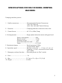
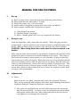
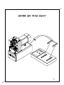
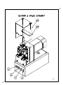
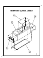
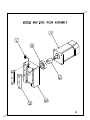
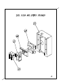
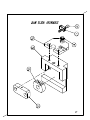
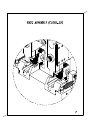
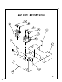
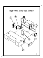
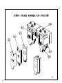
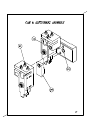
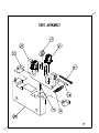
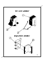
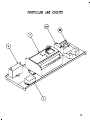
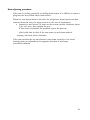
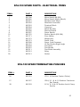
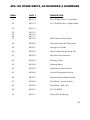
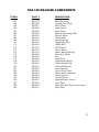
SENTINEL
®
CONNECTOR SYSTEMS
SPA-100 MODULAR PLUG
APPLICATOR
Sentinel Connector Systems
1953 Stanton Street
York, Pa. 17404
Ph. 717-843-4240
SENTINEL
CONNECTOR
SYSTEMS
SPA-100
MACHINE
MANUAL
INTRODUCTION
Your SPA-100 machine comes to you fully equipped and set up to terminate
the style of plug you have requested.
The SPA-100 will accommodate those small connector configurations such
as 4 position, 4 contacts (4x4); 6 position, 2 contacts (2x6); 6 position, 4 contacts
(4x6); and 6 position, 6 contacts (6x6). -Consult factoryWhen set-up to do so, this machine will accommodate both small and large
connectors alike, easy changeover from one to the other.
It is also electrically powered and does not require high-pressure airlines. It
is are portable enough to be moved around easily and their straightforward design
allows setup people to make changes in minutes.
All machines have full test capability with the cable tests performed as part
of the termination procedure.
1
SPECIFICATIONS FOR SPA-100 MODEL CRIMPING
MACHINES
Crimping machine portion
1. Usable connectors…………………Recommended Sentinel Connectors
8x8, Cat 5 &Cat 6
(4x4, 2x6, 4x6, 6x6 Consult factory)
2. Function ………………………….. Crimping modular connectors onto cable
3.
Power Source ……………………. AC 115v, 60Hz, 5Amp
4. Driving System …………………… Single phase induction motor with gear head
Power consumption …………… 90w
Rated current ………………….. 0.75A
Starting current ……………….. 1.9A
Gear head reduction ratio …… 30:1
Power………………………………1/10 H.P.
5. Mechanical power ……………….. Punch pressure 130Kg
Punch stroke 16mm
6. Operation speed …………………. Machine cycle time …… 1.5 sec. (1.1 sec. of
Crimping + 0.5 sec. of electrical check under
10 ft. cable)
7. Emergency release function ……Reversing motor by “Rev” switch
8. Fuse ………………………………… 5 A
9. Size ……………………………….. 5.5” (w) x 10
10. Weight ……………………………. 40.4lbs
5/8
(h) x 13 1/8 (d)
2
MANUAL FOR SPA-100 PRESS
I.
Set-up
A)
B)
C)
D)
E)
Refer to page 6 for a pictorial view while following instructions.
Plug press into the wall outlet 110 volts.
Plug cable tester into 110 volts outlet.
Attach cables (supplied) to press and cable tester as labeled.
Select proper combination of switches on press.
1) “Auto/Hand” (on press)
2) “Double/Single” (on press)
3) With a “known good cable” set-up a signature (on tester).
II.
Ready to run
With the signature cable, insert into the nest(s). When the plug reaches
proper depth, a micro switch in rear of nest actuates a single rotation of the
press. When a single plug is required, only the left nest can be utilized.
CAUTION: When using both nests, make sure the selector switch is on
double!
After ram on press has returned to top position, maintain the position of the
plugs in the nest to insure an accurate reading on the tester. The plugs in
the nests will actuate a micro switch to cycle machine, (if plug is removed
and reinserted it will cycle again). When the ram is at it top position the test
wires are making contact with the gold pins in the plugs, this will allow the
tester to check continuity, shorts and correct polarity of plugs to wire. This
test will remain active as long as plugs remain in the nests. Once the plug
moves away from the micro switch in rear of nest, the machine resets itself
to begin a new termination.
III.
Adjustments
A) Nests
Both nests are in a fixed position and cannot be adjusted. However,
They can be removed and replaced with other nests allowing termination
of various Sentinel Connector Systems connectors.
1) The nests are equipped with two ball vilers that seat the connector
into the nest securely. At times it may be necessary to remove these
and replace them with new, when doing this please be sure not to
over tighten as to damage the connector.
3
B) Punch holder assembly
The punches can also be adjusted as a unit or individually.
To move punches as a unit, loosen the two cap screws in the front of the
head (item #65, page 18), move the head up or down using the screw on
top (item #64 page13) for adjusting, and retighten screws when proper
position is located.
C) Punches
1) In order to make individual adjustments of the punches, there are
small slotted screws on the top (item #60 page 17) of punch holder
assembly. To make an adjustment first loosen screw (item #69 page
17) in front and the set screw on the side of punch holder assembly
(item #61 page17). Make the desired adjustments (NOTE: one
complete turn of #60 screw is equivalent to .020 or 5mm). When the
movement is made, push tooling up while lightly snugging the set
screws on the side (item #61); then tighten the screws in front (item
#69).
2) Any adjustment left to right can be made if necessary by loosening the
screws at (item#66) adjustment required can be made by adjusting the
proper tool unit in direction desired. (see step 3 for a detailed
description of how to make alignment.
3) Try this when lining up connector to punch. Remove the two punches
on the side needing adjustment(left or right). Leave the contact punch
installed, being held by set screw on the side of the unit. Now place a
pre-inserted connector into the nest and jog the ram down just above
the connector. With a small magnifying glass you will be able to see
which way the tools need to move in relationship to the connector.
You will now be able to make this adjustment. Loosen the proper
bolts that move this unit and adjust. Retighten the bolts and return
ram to its top position. Replace the punches and retighten them.
4) Strip the jacket cord, trim the conductor to length, place a connector
on both ends of cord and insert the plugs into the nest.
5) When a cycle is made the test fingers will remain on the conncetor and
test for shorts, continuity and miswires. If the product is ok and
meets the desired signature, the tester will display a “good reading”.
6) If there is a short or other problem, a tone will be heard and “error”
will be displayed on the screen. Test fingers will stay down, touching
the contacts, until at least one of the plugs has been removed from the
nest, deactivating the micro switch.
7) If for some reason the ram does not return to its original position after
crimping, turn the switch (labeled rev) on to return the ram manually.
When ram is at the top, turn rev switch off before.
4
TERMINATION INSTRUCTIONS
These instructions are intended for use with the SPA-100 in conjunction
with Sentinel Connectors modular plugs.
This product comes to you in single assemblies with contacts pre-inserted.
Please refer to product manual for details on determining which of Sentinel’s plugs
will work the best for your application. Any further help may be obtained by
contacting Sentinel direct and obtaining the proper guides.
Once you have determined which combination is best suited, strip the cable
back far enough to allow the individual conductors to be inserted into the plug
while also maintaining the outer jacket positioned under the jacket lock on the
plug. Position the conductors, as desired, and insert them into the plug, making
sure the conductors, as desired, and insert them into the plug, making sure the
conductors are securely positioned against the front of the plastic, to ensure the
contacts penetrate properly.
After preparing cables with connectors, you are ready for termination. If only
one plug is required to be terminated, switch machine to single. If both are
desired, switch the button to double. This will allow you to properly align both
connectors before the ram cycles down. After the ram completes the cycle,
(keeping the plugs positioned in the nests) the test leads will come down, testing
for continuity, shorts and opens. If the tested cable is defective, the tester will
indicate exactly what the defect is. For further instructions on the tester, refer to
the tester manual provided.
Once the cable is completed, a contact height check is necessary to maintain
compliance with FCC, which is .237 +/- .005 from the bottom of the plug base (not
including the tab) to the top of the contacts. This is roughly .023 from the top of
the plug to the contacts at a nominal tolerance.
The tooling can be replaced relatively simply and quickly for short down
time. Each tool can be adjusted individually or as a unit depending on what the
need is.
The machine can be adjusted manually by removing motor guard to obtain
access. Then turn the power off and rotate the fan in the direction desired (the
ram will go up or down depending on the direction fan is turned clockwise or
counter clockwise). Rotate the motor until ram comes down to a plug inserted into
the nest for any adjustment necessary (the contacts in the plug should align with
the contacts that do the driving). After making the adjustment, continue rotating
the motor either way until the ram reaches the top and makes contact with the
micro switch.
7
RECEIVING INSPECTION
This machine has been thoroughly inspected before leaving our facility. This
provides the assurance that the machine produces good termination and
Is ready to use. However, the following points should be reviewed to verify that no
problems have occurred during shipment.
1. Carefully uncrate the machine and place it on a sturdy bench and
examine it against the report sent with machine.
2. Inspect the entire machine for evidence of damage that may have
occurred during transit. If in fact the machine shows signs of damage,
contact Sentinel Connector Systems, Inc. immediately.
3. Check all components to be certain they are secure. Don’t operate
machine until all loose tooling has been tightened down safely.
4. Please maintain the crate the machine has been delivered. In the event
the machine has need of repairs or lease if terminated the machine must
be sent back in its original crate. This is to maintain proper protection of
the machine from any shipping damage. Your help in this manner is
greatly appreciated.
5.
8
SPA-100 SPARE TOOLING
Suggested Spare tooling for the SPA-100 machine is as follows:
A. One each machine – 901306 micro switch
B. Two each machine - 902300 micro switch
C. One pair of contact punches on most used product
8-position 901053 contact driver
TROUBLE SHOOTING TIPS
Motor will not run
Check the relays in rear of machine. They may have
come loose during shipment.
Ram cycling continuously
up and down or drifting
Check the micro switch at the top of machine for
proper placement and/or not working. Check break
pac relay to ensure it is working properly. (see
adjustment notes below)
No cycle on auto
Micro switch in nest may be faulty, or may be
pushed too far. There maybe lint build-up. Check
both nests.
Testing displaying error;
product looks fine
Tooling may be out of adjustment, causing
plastic skiving of the ribs which insulates the
test probes from the contacts.
If test leads don’t have enough bend on the
front, they may not snap down between the ribs
to make continuity with the contacts in the plug.
22
MAINTENANCE FOR SPA-100
1.
Use a soft brush to lightly remove any debris that may build up on machine.
Always keep the nest cavity clean.
2.
Grease machine at the top, once a month or every 500 hours of service.
With the machine off, take a cloth underneath the ram and remove excess
grease. This should be done from time to time between greasings to assure
that grease does not come in contact with product.
3.
When replacing tooling, store unused tooling in plastic or wax paper after
being lightly sprayed with light oil. When replacing tooling lightly brush off
tooling working surfaces and wipe oil clean from tooling. Do not oil the
gibbs, as this will break down the grease that has been placed in them from
the factory.
4.
A maintenance program should be established for service on a regular basis.
The amount of usage will determine whether this should be performed daily,
weekly or monthly.
5.
Take extra care that no chemicals remain in the nest portion of the machine
when resuming production. This will prevent any possible chemical
reaction.
6.
Contact a service representative for any further information.
WARNING! When maintenance is being performed, please make sure
power is off!
23
Ram adjusting procedure:
If the ram is cycling erratically or drifting down where it is difficult to insert a
plug into the nest, follow these instructions.
When the ram drops down to low after the plugs have been tested and then
removed from the nest, the micro switch is a bit out of adjustment.
• Loosen the nut (item #72) and turn the screw counter clockwise about
1/8th of a turn, then tighten the nut.
If this doesn’t eliminate the problem repeat the process.
(this could also be done if the ram runs up and down without
stoping.) but turn screw clockwise.
If the ram reaches the top and doesn’t come down properly to it’s initial
starting point an adjustment the opposite direction is necessary
(counterclockdwise).
24
SPA-100 SPARE PARTS – ELECTRICAL ITEMS
ITEM #
1
2
3
4
5
6
7
8
9
10
11
12
13
14
15
16
17
18
19
20
PART #
DESCRIPTION
901306
902300
902301
902302
902303
902304
902305
902306
902307
901370
901371
901372
901373
902308
901375
902309
902310
902311
902312
902313
Micro Switch SS-SGL
Micro Switch (Radio Shack)
Brothers Gear Motor
Mitubishi Controller
Terminal Block
Capacitor
Break Rectifier
Reverse Switch
Power Switch
Rocker Switch (DS-308)
Fuse Holder
Midget fuse
Power Cord
Power Cord Grommet
20 Pin Header-Right Angle
Test Wires
Test Blocks
Test Block Assembly
Relay
Socket
SPA-100 SPARE TERMINATING PUNCHES
ITEM #
PART #
DESCRIPTION
26
901053
CD-8 (8 Position Contact Driver)
27
901057
28
901059
CB-8/10 (8 & 10 Position Conductor
Bar Punch)
LC-8/10 (8 & 10 Position Latch Crimp
Punch)
25
SPA-100 SPARE NESTS, ACCESSORIES & HARDWARE
ITEM #
PART #
DESCRIPTION
51
901112
8/10 Position Nest – Left Hand
52
901113
8/10 Position Nest – Right Hand
53
901114
54
55
56
57
901115
901116
901117
901125
Ball Vilers for Plug Nests
58
902100
Ground Screws for Plug Nests
59
902101
Springs on Testers
60
902102
Punch Adjusting Screw & Nut
61
902103
Set Screws for Punches
62
902104
Bearing Tester
63
901348
Bearing Motor
64
902105
Adjustment Screw & Nut
65
902106
Vertical Adjustment Screw
66
902107
Horizontal Adjustment Screw
67
902108
Test Block Screw & Nuts
68
902109
Test Block Slide Pin
69
902110
#10-32 SHCS
70
902111
Dowel Pin for Spring
26
SPA-100 MACHINE COMPONENTS
ITEM #
101
102
103
104
105
106
107
108
109
110
111
112
113
114
115
116
117
118
119
120
121
122
123
124
125
126
127
128
129
PART #
DESCRIPTION
902325
902326
902327
902328
902329
902330
902331
902332
902333
902334
902334
902335
901353
901318
902336
902337
902338
902339
902340
902341
902342
902343
902344
902345
902346
902347
902349
902350
902351
Machine Base
Upright Tool Slide
Base Cover
Front Panel
Rear Panel
Bottom Mounting Plate
Spacer Block
Nest Holder
Left Plug Stop
Right Plug Stop
Guide Rail
Slide Block
Guide Block
Brass Ram Bushing
Eccentric Shaft
Key
Slide Stop
Adjustment Block
Punch Holder RH
Punch Holder LH
Pivot Bracket
Tester Pivot Plate
Micro Switch Bracket
Guard Spacer
Guard Spacer
Main Machine Guard
Cam Plate
Main Machine Spacer for Guard
Stop Plate
27