1
Brother Laser Printer
SERVICE MANUAL
MODEL:
HL-5440D/5450DN/5450DNT
HL-5470DW/5470DWT
HL-6180DW/6180DWT
Read this manual thoroughly before maintenance work.
Keep this manual in a convenient place for quick and easy reference at all times.
Feb 2012
SM-PRN084
84UD*
(1)
Confidential
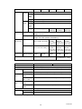
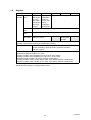
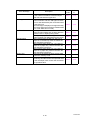
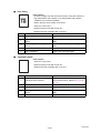
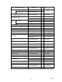
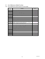
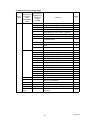
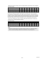
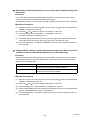
The function comparative table for models as described in this Service Manual are shown below.
HL-5440D
HL-5450DN
HL-5450DNT
HL-5470DW
HL-5470DWT
LCD/LED
Model
LED
LED
LED
LCD
LCD
Wired/Wireless
LAN
N/A
Wired
Wired
Wired/
Wireless
Wired/
Wireless
Parallel port
9
N/A
N/A
N/A
N/A
Paper Tray 1
250 sheets
250 sheets
250 sheets
250 sheets
250 sheets
Paper Tray 2
Option
(500 sheets)
Option
(500 sheets)
Standard
Equipment
(500 sheets)
Option
(500 sheets)
Standard
Equipment
(500 sheets)
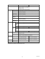
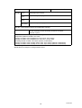
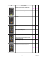
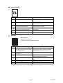
HL-6180DW
HL-6180DWT
LCD
LCD
Wired/
Wireless
Wired/
Wireless
Parallel port
N/A
N/A
Paper Tray 1
500 sheets
500 sheets
Paper Tray 2
Option
(500 sheets)
Standard
Equipment
(500 sheets)
Model
LCD/LED
Wired/Wireless
LAN
© Copyright Brother 2012
All rights reserved.
No part of this publication may be reproduced in any form or by any means without permission in writing
from the publisher.
All other product and company names mentioned in this manual are trademarks or registered
trademarks of their respective holders.
Specifications are subject to change without notice.
Confidential
TRADEMARKS
The Brother logo is a registered trademark of Brother Industries, Ltd.
Brother is a registered trademark of Brother Industries, Ltd.
Multi-Function Link is a registered trademark of Brother International Corporation.
Windows Vista is either a registered trademark or trademark of Microsoft Corporation in the United
States and/or other countries.
Microsoft, Windows, Windows Server and Internet Explorer are registered trademarks of Microsoft
Corporation in the United States and/or other countries.
Apple and Macintosh are trademarks of Apple Inc., registered in the United States and other countries.
Adobe, Flash, Illustrator, PageMaker and Photoshop are either registered trademarks or trademarks of
Adobe Systems Incorporated in the United States and/or other countries.
Nuance, the Nuance logo, PaperPort and ScanSoft are trademarks or registered trademarks of Nuance
Communications, Inc. or its affiliates in the United States and/or other countries.
PowerPC is a trademark of International Business Machines Corporation.
Memory Stick, Memory Stick PRO, Memory Stick PRO Duo, Memory Stick Duo, MagicGate Memory
Stick, Memory Stick Micro and M2 are trademarks of Sony Corporation.
AOSS is a trademark of Buffalo Inc.
Wi-Fi, WPA, WPA2, Wi-Fi Protected Access and Wi-Fi Protected Setup are either trademarks or
registered trademarks of Wi-Fi Alliance in the United States and/or other countries.
Intel and Pentium are trademarks of Intel Corporation in the U.S. and other countries.
AMD is a trademark of Advanced Micro Devices, Inc.
FaceFilter Studio is a trademark of Reallusion, Inc.
BRAdmin Professional is a trademark of Brother Industries, Ltd.
UNIX is a registered trademark of The Open Group.
Linux is the registered trademark of Linus Torvalds in the U.S. and other countries.
CorelDraw, Corel Paint Shop Pro and Corel WordPerfect are trademarks or registered trademarks of
Corel Corporation and/or its subsidiaries in Canada, the United States and/or other countries.
Each company whose software title is mentioned in this manual has a Software License Agreement
specific to its proprietary programs.
Any trade names and product names of companies appearing on Brother products, related documents
and any other materials are all trademarks or registered trademarks of those respective companies.
Confidential
CONTENTS
REGULATION .......................................................................................................... vii
SAFETY INFORMATION......................................................................................... xiii
CHAPTER 1
SPECIFICATIONS
1. SPECIFICATIONS LIST ............................................................................................................... 1-1
1.1
General ................................................................................................................................ 1-1
1.2
Network Connectivity ........................................................................................................... 1-5
1.3
Service Information.............................................................................................................. 1-6
1.4
Supplies ............................................................................................................................... 1-7
1.5
Paper ................................................................................................................................... 1-9
1.6
1.5.1
Paper handling ...................................................................................................... 1-9
1.5.2
Media specifications .............................................................................................. 1-9
1.5.3
Type and size of paper........................................................................................ 1-10
Printable Area .................................................................................................................... 1-11
CHAPTER 2
TROUBLESHOOTING
1. INTRODUCTION .......................................................................................................................... 2-1
1.1
Precautions.......................................................................................................................... 2-1
1.2
Checks before Commencing Troubleshooting..................................................................... 2-2
2. OVERVIEW .................................................................................................................................. 2-4
2.1
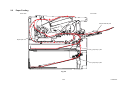
Cross-section Drawing......................................................................................................... 2-4
2.2
Paper Feeding ..................................................................................................................... 2-5
2.3
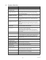
Operation of Each Part ........................................................................................................ 2-6
2.4
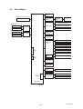
Block Diagram ..................................................................................................................... 2-8
2.5
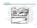
Main Components................................................................................................................ 2-9
3. ERROR INDICATIONS............................................................................................................... 2-10
3.1
Error Codes ....................................................................................................................... 2-10
3.2
Error Messages ................................................................................................................. 2-16
3.3
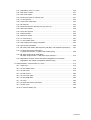
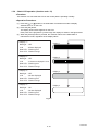
LED Display (LED Model).................................................................................................. 2-19
3.3.1
LED display when operator call occurs ............................................................... 2-19
3.3.2
LED display when service call occurs ................................................................. 2-23
4. TROUBLESHOOTING ............................................................................................................... 2-28
4.1
Error Cause and Remedy .................................................................................................. 2-28
4.2
Troubleshooting for Paper Feeding Problems ................................................................... 2-57
4.2.1
Multiple sheets of paper are fed .......................................................................... 2-57
4.2.2
Paper becomes wrinkled ..................................................................................... 2-57
4.2.3
Paper is fed at an angle ...................................................................................... 2-57
i
Confidential
4.3
4.4
4.2.4
Duplex printing is not possible............................................................................. 2-58
4.2.5
Paper is curled .................................................................................................... 2-58
4.2.6
Only single surface is printed in duplex printing mode ........................................ 2-58
Troubleshooting for Image Defects.................................................................................... 2-59
4.3.1
Image defect examples ....................................................................................... 2-59
4.3.2
Troubleshooting according to image defect ........................................................ 2-60
Troubleshooting for Software Problems ............................................................................ 2-73
4.4.1
4.5
4.6
4.7
4.8
Troubleshooting for Network Problems ............................................................................. 2-74
4.5.1
Cannot print via network connection ................................................................... 2-74
4.5.2
Cannot connect to access point .......................................................................... 2-74
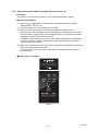
Troubleshooting for Control Panel Problems..................................................................... 2-75
4.6.1
Nothing is displayed on the LCD ......................................................................... 2-75
4.6.2
LEDs are not activated ........................................................................................ 2-75
4.6.3
Control panel is inoperable.................................................................................. 2-75
Troubleshooting for Toner and Drum Problems ................................................................ 2-76
4.7.1
New toner is not detected.................................................................................... 2-76
4.7.2
Cartridge error (toner cartridge cannot be detected)........................................... 2-76
4.7.3
Drum error ........................................................................................................... 2-76
Troubleshooting for Fuser Unit Problems .......................................................................... 2-77
4.8.1
4.9
Cannot print data................................................................................................. 2-73
Fuser unit failure.................................................................................................. 2-77
Troubleshooting for Laser Unit Problems .......................................................................... 2-78
4.9.1
Laser unit failure.................................................................................................. 2-78
4.10 Troubleshooting for PCB Problems ................................................................................... 2-79
4.10.1
Main PCB failure ................................................................................................. 2-79
4.10.2
High-voltage power supply PCB failure............................................................... 2-79
4.10.3
Low-voltage power supply PCB failure................................................................ 2-79
4.11 Troubleshooting for Other Problems.................................................................................. 2-80
4.11.1
Machine is not turned ON.................................................................................... 2-80
4.11.2
Main fan does not rotate...................................................................................... 2-80
4.11.3
Main motor failure................................................................................................ 2-80
4.11.4
Unusual noise is generated from the machine .................................................... 2-80
CHAPTER 3
DISASSEMBLY/REASSEMBLY
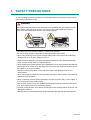
1. SAFETY PRECAUTIONS............................................................................................................. 3-1
2. PACKING ..................................................................................................................................... 3-2
3. SCREW CATALOGUE................................................................................................................. 3-3
4. SCREW TORQUE LIST ............................................................................................................... 3-4
5. LUBRICATION ............................................................................................................................. 3-6
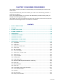
6. OVERVIEW OF GEARS............................................................................................................... 3-7
7. HARNESS ROUTING................................................................................................................... 3-9
8. DISASSEMBLY FLOW CHART................................................................................................. 3-14
ii
Confidential
9. DISASSEMBLY PROCEDURE .................................................................................................. 3-15
9.1
Preparation ........................................................................................................................ 3-15
9.2
Paper tray 1 ....................................................................................................................... 3-16
9.3
Back cover / Outer chute ................................................................................................... 3-18
9.4
Fuser cover........................................................................................................................ 3-19
9.5
MP cover ASSY ................................................................................................................. 3-20
9.6
Front cover ASSY .............................................................................................................. 3-21
9.7
Side cover L / Access cover .............................................................................................. 3-22
9.8
Side cover R ...................................................................................................................... 3-23
9.9
Top cover ASSY ................................................................................................................ 3-24
9.10 Control panel ..................................................................................................................... 3-26
9.11 Paper stack lever ............................................................................................................... 3-29
9.12 Wireless LAN PCB (Wireless Network model only)........................................................... 3-30
9.13 Fuser unit........................................................................................................................... 3-31
9.14 Main PCB ASSY ................................................................................................................ 3-34
9.15 Laser unit ........................................................................................................................... 3-36
9.16 Low-voltage power supply PCB ASSY .............................................................................. 3-37
9.17 Toner LED PCB ASSY ...................................................................................................... 3-40
9.18 Main fan ............................................................................................................................. 3-42
9.19 Air duct / Filter.................................................................................................................... 3-44
9.20 Relay front PCB ASSY ...................................................................................................... 3-45
9.21 Registration clutch / T1 clutch............................................................................................ 3-46
9.22 Main frame L ASSY ........................................................................................................... 3-47
9.23 Main motor ASSY .............................................................................................................. 3-49
9.24 Develop joint gear 37 / Develop joint ................................................................................. 3-51
9.25 LT drive gear 29................................................................................................................. 3-52
9.26 Toner sensor PCB ASSY................................................................................................... 3-53
9.27 MP solenoid ....................................................................................................................... 3-54
9.28 Develop clutch 51R / Develop one way clutch 53.............................................................. 3-55
9.29 New toner actuator ............................................................................................................ 3-56
9.30 Fuser drive gear 39............................................................................................................ 3-57
9.31 Duplex solenoid ................................................................................................................. 3-59
9.32 Back cover sensor ............................................................................................................. 3-60
9.33 LT connector (T1) .............................................................................................................. 3-61
9.34 T1 roller holder ASSY ........................................................................................................ 3-62
9.35 High-voltage power supply PCB ASSY ............................................................................. 3-63
9.36 Eject sensor PCB ASSY .................................................................................................... 3-66
9.37 MP roller holder ASSY / MP separation pad ASSY / MP separation pad spring ............... 3-67
9.38 T1 paper feed sensor PCB ASSY /
T1 paper feed actuator / T1 paper feed actuator spring .................................................... 3-68
9.39 MP paper empty sensor PCB ASSY /
MP paper empty actuator 1 / MP paper empty actuator 2 ................................................. 3-70
iii
Confidential
9.40 Registration front/rear sensor PCB ASSY / Registration front actuator
/ Registration rear actuator / Registration actuator spring ................................................. 3-73
10. DISASSEMBLY PROCEDURE (LT UNIT)................................................................................. 3-76
10.1 Paper tray 2 ....................................................................................................................... 3-76
10.2 T2 roller holder ASSY ........................................................................................................ 3-78
10.3 T2 side cover L .................................................................................................................. 3-79
10.4 T2 side cover R.................................................................................................................. 3-80
10.5 T2 front cover ASSY .......................................................................................................... 3-81
10.6 T2 relay PCB ASSY........................................................................................................... 3-82
10.7 T2 clutch ............................................................................................................................ 3-83
10.8 T2 paper feed sensor PCB ASSY...................................................................................... 3-84
10.9 T2 back cover .................................................................................................................... 3-88
10.10LT connector ASSY (T2).................................................................................................... 3-89
CHAPTER 4
ADJUSTING AND UPDATING SETTINGS
AS REQUIRED AFTER PARTS REPLACEMENT
1. IF YOU REPLACE THE MAIN PCB ASSY .................................................................................. 4-1
1.1
Installing Firmware (Sub Firmware, Main Firmware) ........................................................... 4-2
1.1.1
Checking firmware version .................................................................................... 4-2
1.1.2
Installing firmware ................................................................................................. 4-2
1.2
Setting Default Paper Size................................................................................................... 4-4
1.3
Setting Serial Number and Entering Adjusted Value of Laser Unit...................................... 4-5
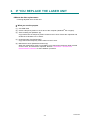
2. IF YOU REPLACE THE LASER UNIT ......................................................................................... 4-7
2.1
Entering Adjusted Value of Laser Unit................................................................................. 4-8
3. IF YOU REPLACE THE LOW-VOLTAGE POWER SUPPLY PCB ASSY ................................ 4-10
3.1
Resetting Irregular Power Supply Detection Counter ........................................................ 4-10
4. IF YOU REPLACE THE HIGH-VOLTAGE POWER SUPPLY PCB ASSY................................ 4-11
4.1
Initializing Pre-discharge Detection Parameters................................................................ 4-11
5. IF YOU REPLACE ANY PERIODIC REPLACEMENT PARTS ................................................. 4-12
5.1
Resetting Counter of Periodic Replacement Parts ............................................................ 4-12
CHAPTER 5
SERVICE FUNCTIONS
1. MAINTENANCE MODE................................................................................................................ 5-1
1.1
1.2
1.3
How to Enter Maintenance Mode ........................................................................................ 5-1
1.1.1
Method of entering end-user accessible maintenance mode................................ 5-1
1.1.2
Method of entering maintenance mode for service personnel .............................. 5-2
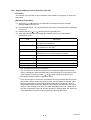
List of Maintenance Mode Functions ................................................................................... 5-3
1.2.1
List of maintenance mode functions for LCD models............................................ 5-3
1.2.2
List of maintenance mode functions using [Go] button for LED models................ 5-4
Details of Maintenance Mode Functions for LCD Models.................................................... 5-6
1.3.1
Initialize EEPROM parameters (function code: 01, 91)......................................... 5-6
1.3.2
Print test pattern (function code: 09) ..................................................................... 5-7
iv
Confidential
1.4
1.3.3
Set worker switches (WSW) and print worker switch setting data
(function code: 10, 11)........................................................................................... 5-8
1.3.4
Check LCD operation (function code: 12) ........................................................... 5-10
1.3.5
Check control panel button operation (function code: 13)................................... 5-11
1.3.6
Display software version (function code: 25)....................................................... 5-12
1.3.7
Set One Push Demo function (function code: 28) ............................................... 5-13
1.3.8
Check sensor operation (function code: 32)........................................................ 5-14
1.3.9
Display LAN connection status (function code: 33)............................................. 5-16
1.3.10
Print Dump List (function code: 40) ..................................................................... 5-17
1.3.11
Change USB No. return value /
Adjust left-end print start position on second side when duplex printing /
Change ON/OFF setting for Deep Sleep function (function code: 45) ................ 5-18
1.3.12
Continuous print test (function code: 67)............................................................. 5-20
1.3.13
Print frame pattern (single-side printing) (function code: 69) .............................. 5-22
1.3.14
Print frame pattern (duplex printing) (function code: 70) ..................................... 5-24
1.3.15
Print solid pattern (function code: 71).................................................................. 5-26
1.3.16
Setting by country (function code: 74)................................................................. 5-27
1.3.17
Print maintenance information (function code: 77).............................................. 5-29
1.3.18
Check fan operation (function code: 78) ............................................................. 5-31
1.3.19
Display machine log information (function code: 80)........................................... 5-32
1.3.20
Display machine error code (function code: 82).................................................. 5-34
1.3.21
Quit maintenance mode (function code: 99) ....................................................... 5-34
Details of Maintenance Mode Functions Using [Go] Button for LED Models .................... 5-35
1.4.1
Test printing......................................................................................................... 5-35
1.4.2
Print font list......................................................................................................... 5-36
1.4.3
Change USB No. return value............................................................................. 5-36
1.4.4
HEX Dump mode ................................................................................................ 5-36
1.4.5
Network Reset / Factory Reset / Settings Reset ................................................. 5-36
1.4.6
Engine error ignore mode.................................................................................... 5-37
1.4.7
One Push print recovery mode............................................................................ 5-37
1.4.8
Check sensor operation ...................................................................................... 5-38
1.4.9
Print continuous lattice pattern ............................................................................ 5-39
1.4.10
Print fuser unit inspection .................................................................................... 5-39
1.4.11
Print EEPROM Dump.......................................................................................... 5-40
1.4.12
Check RAM ......................................................................................................... 5-40
1.4.13
Print machine quality inspection pattern 1........................................................... 5-41
1.4.14
Change ON/OFF setting for duplex printing ........................................................ 5-42
1.4.15
Change A4/Letter setting for paper size.............................................................. 5-42
1.4.16
Print machine quality inspection pattern 2........................................................... 5-43
1.4.17
Maintenance printing ........................................................................................... 5-44
1.4.18
Print maintenance data and frame pattern .......................................................... 5-46
1.4.19
Print Network Configuration ................................................................................ 5-47
1.4.20
Change ON/OFF setting for sleep function ......................................................... 5-47
1.4.21
Reset developer roller counter 1, 2, 3 or 4 (Common to all models) ................... 5-47
1.4.22
USB speed lock mode......................................................................................... 5-47
1.4.23
Change Ready LED light intensity in sleep mode ............................................... 5-48
1.4.24
Firmware Installing mode .................................................................................... 5-48
1.4.25
Enter maintenance mode for service personnel.................................................. 5-48
v
Confidential
2. PRINTER SETTINGS ................................................................................................................. 5-49
2.1
Printing Printer Settings ..................................................................................................... 5-49
3. OTHER SERVICE FUNCTIONS................................................................................................. 5-57
3.1
Change ON/OFF Setting for Deep Sleep Mode (LCD model only) ................................... 5-57
3.2
Change ON/OFF Setting for Sleep Mode (LCD model only) ............................................. 5-57
3.3
Reset Periodic Replacement Parts (LCD model only)....................................................... 5-58
3.4
Delete User Setting Information (LCD model only)............................................................ 5-58
3.5
Change USB No. Return Value /
Adjust Left-end Print Start Position on Second Side when Duplex Printing /
Change ON/OFF Setting for Deep Sleep Function (LCD model only)............................... 5-59
3.6
Reset Drum Counter (LED model only) ............................................................................. 5-61
3.7
Change Active/Inactive Setting for Wireless LAN (Wireless Network Model only) ............ 5-61
CHAPTER 6
WIRING DIAGRAM
1. WIRING DIAGRAM ...................................................................................................................... 6-1
CHAPTER 7
PERIODICAL MAINTENANCE
1. SAFETY PRECAUTIONS............................................................................................................. 7-1
2. PERIODICAL REPLACEMENT PARTS ...................................................................................... 7-2
2.1
Preparation .......................................................................................................................... 7-2
2.2
Fuser unit............................................................................................................................. 7-3
2.3
Laser unit ............................................................................................................................. 7-7
2.4
MP paper feeding kit.......................................................................................................... 7-12
2.5
Paper feeding kit 1............................................................................................................. 7-13
2.6
Paper feeding kit 2............................................................................................................. 7-15
APPENDIX 1 SERIAL NUMBERING SYSTEM
APPENDIX 2 DELETING USER SETTING INFORMATION
APPENDIX 3 INSTALLING MAINTENANCE DRIVER
vi
Confidential
REGULATION
Declaration of Conformity (Europe only)
(HL-5470DW / HL-6180DW(T) only)
We, Brother Industries, Ltd. of 15-1, Naeshiro-cho, Mizuho-ku, Nagoya 467-8561 Japan
declare that this product is in compliance with the essential requirements of Directives
1999/5/EC and 2009/125/EC.
The Declaration of Conformity (DoC) is available on our Website.
Please go to http://solutions.brother.com/.
• choose region (eg. Europe)
• choose country
• choose your model
• choose “Manuals”
• choose Declaration of Conformity (Select Language when required.)
Declaration of Conformity (Europe only)
(HL-5440D / HL-5450DN(T) only)
We, Brother Industries, Ltd. of 15-1, Naeshiro-cho, Mizuho-ku, Nagoya 467-8561 Japan
declare that this product is in compliance with the essential requirements of Directives
2004/108/EC, 2006/95/EC and 2009/125/EC.
The Declaration of Conformity (DoC) is available on our Website.
Please go to http://solutions.brother.com/.
• choose region (eg. Europe)
• choose country
• choose your model
• choose “Manuals”
• choose Declaration of Conformity (Select Language when required.)
vii
Confidential
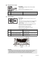
IEC60825-1:2007 Specification
(For 220-240V models only)
This product is a Class 1 laser product as defined in IEC60825-1:2007 specifications.
The label shown below is attached in countries where required.
This product has a Class 3B Laser Diode which emits invisible laser radiation in the Laser
Unit. The Laser Unit should not be opened under any circumstances.
%.#55.#5'4241&7%6
#22#4'+..#5'4&'%.#55'
.#5'4-.#55'241&7-6
Internal laser radiation
Wave Length: 775 - 810 nm
Output: 15 mW max.
Laser Class: Class 3B
WARNING
Use of controls, adjustments or performance of procedures other than those specified
in this manual may result in hazardous radiation exposure.
Disconnect Device
CAUTION
This product must be installed near an electrical socket that is easily accessible. In
case of emergencies, you must disconnect the power cord from the electrical socket
to shut off power completely.
Wiring Information (U.K. only)
If you need to replace the plug fuse, fit a fuse that is approved by ASTA to BS1362 with the
same rating as the original fuse.
Always replace the fuse cover. Never use a plug that does not have a cover. If in any doubt,
call a qualified electrician.
Warning -This product must be earthed.
The wires in the mains lead are coloured in line with the following code:
• Green and Yellow: Earth
• Blue: Neutral
• Brown: Live
LAN Connection (Network models only)
CAUTION
DO NOT connect this product to a LAN connection that is subject to over-voltages.
viii
Confidential
Radio Interference
This product complies with EN55022 (CISPR Publication 22)/Class B.
Recycling Information in accordance with the WEEE (2002/96/EC) and
Battery (2006/66/EC) Directives
Product mark
Battery mark
European Union only
The product/battery is marked with one of the above recycling symbols. It indicates that at
the end of the life of the product/battery, you should dispose of it separately at an appropriate
collection point and not place it in the normal domestic waste stream.
ix
Confidential
Federal Communications Commission (FCC) Declaration of Conformity
(USA only)
Responsible Party:
Brother International Corporation
100 Somerset Corporate Boulevard
Bridgewater, NJ 08807-0911 USA
Tel: (908) 704-1700
declares, that the products
Product name:
HL-5440D/HL-5450DN/HL-5470DW/HL-5470DWT/
HL-6180DW/HL-6180DWT
Model numbers:
HL-54/HL-61
Product option:
LT-5400
comply with Part 15 of the FCC Rules. Operation is subject to the following two conditions:
(1) This device may not cause harmful interference, and (2) this device must accept any
interference received, including interference that may cause undesired operation.
This equipment has been tested and found to comply with the limits for a Class B digital
device, pursuant to Part 15 of the FCC Rules. These limits are designed to provide
reasonable protection against harmful interference in a residential installation. This
equipment generates, uses, and can radiate radio frequency energy and, if not installed and
used in accordance with the instructions, may cause harmful interference to radio
communications. However, there is no guarantee that interference will not occur in a
particular installation. If this equipment does cause harmful interference to radio or television
reception, which can be determined by turning the equipment off and on, the user is
encouraged to try to correct the interference by one or more of the following measures:
• Reorient or relocate the receiving antenna.
• Increase the separation between the equipment and receiver.
• Connect the equipment into an outlet on a circuit different from that to which the receiver is
connected.
• Call the dealer or an experienced radio/TV technician for help.
(Wireless network models only)
This transmitter must not be co-located or operated in conjunction with any other antenna or
transmitter.
Important
• Changes or modifications not expressly approved by Brother Industries, Ltd. could
void the user’s authority to operate the equipment.
• A shielded interface cable should be used to ensure compliance with the limits for a
Class B digital device.
x
Confidential
Industry Canada Compliance Statement (Canada only)
This Class B digital apparatus complies with Canadian ICES-003.
Cet appareil numérique de la classe B est conforme à la norme NMB-003 du Canada.
Operation is subject to the following two conditions: (1) this device may not cause
interference, and (2) this device must accept any interference, including interference that
may cause undesired operation of this device.
L’utilisation de ce dispositif est autorisée seulement aux conditions suivantes :
(1) il ne doit pas produire de brouillage et (2) l’utilisateur du dispositif doit être prêt à accepter
tout brouillage radioélectrique reçu, même si ce brouillage est susceptible de compromettre
le fonctionnement du dispositif.
Laser Safety (For 110-120V models only)
This equipment is certified as a Class 1 laser product as defined in IEC60825-1:2007
specifications under the U.S. Department of Health and Human Services (DHHS) Radiation
Performance Standard according to the Radiation Control for Health and Safety Act of 1968.
This means that the equipment does not produce hazardous laser radiation.
Since radiation emitted inside the equipment is completely confined within protective
housings and external covers, the laser beam cannot escape from the product during any
phase of user operation.
FDA Regulations (For 110-120V models only)
U.S. Food and Drug Administration (FDA) has implemented regulations for laser products
manufactured on and after August 2, 1976. Compliance is mandatory for products marketed
in the United States. One of the following labels on the back of the product indicates
compliance with the FDA regulations and must be attached to laser products marketed in the
United States.
MANUFACTURED:
BROTHER TECHNOLOGY (SHENZHEN) LTD.
NO6 Gold Garden Ind., Nanling Nanwan, Longgang, Shenzhen, China
This product complies with FDA performance standards for laser products except for
deviations pursuant to Laser Notice No. 50, dated June 24, 2007.
MANUFACTURED:
BROTHER INDUSTRIES (VIETNAM) LTD.
Phuc Dien Industrial Zone Cam Phuc Commune, Cam giang Dist Hai Duong Province,
Vietnam
This product complies with FDA performance standards for laser products except for
deviations pursuant to Laser Notice No. 50, dated June 24, 2007.
xi
Confidential
WARNING
Use of controls, adjustments or performance of procedures other than those specified
in this manual may result in hazardous invisible radiation exposure.
Internal laser radiation
Max. Radiation Power: 15 mW
Wave Length: 775 - 810 nm
Laser Class: Class 3B
For use in the USA or Canada only
These products are made for use in the USA and Canada only.
We cannot recommend using them overseas because the power requirements of your
product may not be compatible with the power available in foreign countries. Using USA or
Canada models overseas is at your own risk and may void your warranty.
International ENERGY STAR® Qualification Statement
The purpose of the International ENERGY STAR® Program is to promote the development
and popularization of energy-efficient office equipment.
As an ENERGY STAR® Partner, Brother Industries, Ltd. has determined that this product
meets the ENERGY STAR® specifications for energy efficiency.
xii
Confidential
SAFETY INFORMATION
WARNING
WARNING indicates a potentially hazardous situation which, if not avoided, could result
in death or serious injuries.
CAUTION
CAUTION indicates a potentially hazardous situation which, if not avoided, may result in
minor or moderate injuries.
Important
Important indicates a potentially hazardous situation which, if not avoided, may result in
damage to property or loss of product functionality.
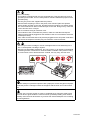
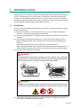
Prohibition icons indicate actions that must not be performed.
Electrical Hazard icons alert you to possible electrical shock.
Fire Hazard icons alert you to the possibility of fire.
Hot Surface icons warn you not to touch product parts that are hot.
Note Notes tell you how you should respond to a situation that may arise or give tips about
how the operation works with other features.
xiii
Confidential
To use the Machine Safely
Please keep these instructions for later reference and read them before attempting any
maintenance. If you do not follow these safety instructions, there is a possibility of a fire,
electrical shock, burn or suffocation.
WARNING
ELECTRICAL HAZARDS
Failure to follow the warnings in this section may create the risk of an electrical shock.
In addition, you could create an electrical short, which may create the risk of a fire.
There are high voltage electrodes inside the product. Before you access the inside of
the product, including for routine maintenance such as cleaning, make sure you have
unplugged the power cord from the AC power outlet, as well as Ethernet (RJ-45)
cables (Network models only) from the product. Never push objects of any kind into
this product through cabinet slots, since they may touch dangerous voltage points or
short out parts.
DO NOT handle the plug with wet hands.
DO NOT use this product during an electrical storm.
Always make sure the plug is fully inserted. DO NOT use the product or handle the
cord if the cord has become worn or frayed.
DO NOT allow this product to come into contact with water.
This product should be connected to an AC power source within the range indicated
on the rating label. DO NOT connect it to a DC power source or inverter.
xiv
Confidential
Power Cord Safety:
• This product is equipped with a 3-wire grounded plug. This plug will only fit into a
grounded power outlet. This is a safety feature. DO NOT defeat the purpose of the
grounded plug.
• Use only the power cord supplied with this product.
• DO NOT allow anything to rest on the power cord. DO NOT place this product
where people can walk on the cord. DO NOT place this product in a position where
the cord is stretched or strain is otherwise put on the cord. Doing so may cause the
cord to become worn or frayed.
• We do not advise using an extension cord.
• If an extension cord is used with this product, make sure that the total ampere
ratings on the products plugged into the extension cord do not exceed the extension
cord ampere rating.
Also, make sure that the total of all products plugged into the AC power outlet does
not exceed 15 amperes. DO NOT plug one extension cord into another.
• DO NOT put a toner cartridge or a toner cartridge and drum unit assembly into a
fire. It could explode, resulting in injuries.
• DO NOT use flammable substances, any type of spray, or an organic solvent/liquid
containing alcohol or ammonia to clean the inside or outside of the product. Doing
so could cause a fire or electrical shock. Instead, use only a dry, lint-free cloth.
DO NOT attempt to operate this product with a paper jam or with stray pieces of paper
inside the product. Prolonged contact of the paper with the drum unit could cause a
fire.
DO NOT use a vacuum cleaner to clean up scattered toner. Doing this might cause
the toner dust to ignite inside the vacuum cleaner, potentially starting a fire. Please
carefully clean the toner dust with a dry, lint-free soft cloth and dispose of it according
to local regulations.
xv
Confidential
HOT SURFACE
After you have just used the product, some internal parts of the product will be
extremely hot. Wait at least 10 minutes for the product to cool down before you touch
the internal parts of the product.
Caution for Laser Product (WARNHINWEIS fur Laser drucker)
CAUTION:
When the machine during servicing is operated with the cover open, the
regulations of VBG 93 and the performance instructions for VBG 93 are
valid.
CAUTION:
In case of any trouble with the laser unit, replace the laser unit itself. To
prevent direct exposure to the laser beam, do not try to open the enclosure
of the laser unit.
ACHTUNG:
Im Falle von Störungen der Lasereinheit muß diese ersetzt werden. Das
Gehäuse der Lasereinheit darf nicht geöffnet werden, da sonst
Laserstrahlen austreten können.
<Location of the laser beam window>
xvi
Confidential
Additional Information
When servicing the optical system of the machine, be careful not to place a screwdriver or
other reflective object in the path of the laser beam. Be sure to take off any personal
accessories such as watches and rings before working on the machine. A reflected beam,
though invisible, can permanently damage the eyes.
Since the beam is invisible, the following caution label is attached on the laser unit.
xvii
Confidential
CHAPTER 1
SPECIFICATIONS
Confidential
CHAPTER 1 SPECIFICATIONS
This chapter lists the specifications of each model.
CONTENTS
1. SPECIFICATIONS LIST ................................................................................................ 1-1
1.1 General.................................................................................................................. 1-1
1.2 Network Connectivity............................................................................................. 1-5
1.3 Service Information................................................................................................ 1-6
1.4 Supplies................................................................................................................. 1-7
1.5 Paper ..................................................................................................................... 1-9
1.5.1 Paper handling ........................................................................................... 1-9
1.5.2 Media specifications ................................................................................... 1-9
1.5.3 Type and size of paper ............................................................................. 1-10
1.6 Printable Area...................................................................................................... 1-11
Confidential
1. SPECIFICATIONS LIST
1.1
General
Model
HL-5440D
HL-5450DN HL-5450DNT HL-5470DW HL-5470DWT
Print method
Electrophotographic Laser Printer
Resolution
1200 x 1200 dpi, HQ1200 (2400 x 600 dpi) quality, 600 x 600 dpi
Print speed One-sided
Up to 38/40 ppm (A4/Letter size)
Warm-up
time
First print
time
Two-sided
18/18 sides per minute (9/9 sheets per minute) (A4/Letter size)
From Sleep
mode
Less than 1 second at 73.4F / 50% (23°C / 50%)
From Power
OFF → ON
Less than 25 seconds at 73.4F / 50% (23°C / 50%)
From Ready
mode
Less than 8.5 seconds at 73.4F (23°C) / 115V or 230V
From Sleep
mode
Less than 10 seconds at 73.4F (23°C) / 115V or 230V
CPU
Memory
StarSapphire 400 MHz
Standard
64 MB
Option
N/A
128 MB
Up to 256 MB (DDR2 16 bit, 144 pin)
Interface
Parallel
Hi-Speed USB 2.0
(IEEE1284) 10Base-T/100Base-TX
Hi-Speed
USB 2.0
Power
Peak
consumption Printing
Average: Approximately 1200 W
Hi-Speed USB 2.0
10Base-T/100Base-TX
IEEE 802.11b/g/n
(Infrastructure Mode /
Adhoc Mode)
Average: Approximately 716 W (for U.S.A.), 665 W (for Europe,
Asia, China, Oceania)
Printing
(Quiet Mode)
Average: Approximately 348 W (for U.S.A.), 332 W (for Europe,
Asia, China, Oceania)
Ready
Average: Approximately 5.0 W (for U.S.A.), 4.7 W (for Europe,
Asia, China, Oceania)
Sleep, Wireless N/A
LAN: ON
Average: Approximately
2.9 W (for U.S.A.), 2.8 W
(for Europe, Asia, Oceania)
Deep Sleep
Average:
Average: Approximately
Approximately 0.6 W
0.7 W
Average: Approximately
0.6 W (for U.S.A.), 0.7 W
(for Europe, Asia, Oceania)
Auto Power
Down Mode
Approximately Approximately 0.41 W (only Approximately 0.5 W (only
0.4 W (only for Europe and GULF)
for Europe and GULF)
for Europe
and GULF)
Specifications are subject to change without notice.
1-1
Confidential
Model
Noise level
HL-5440D
HL-5450DN HL-5450DNT HL-5470DW HL-5470DWT
Sound Printing LpAm = 59 dB (A)
pressure Printing LpAm = 54 dB (A)
(Quiet
Mode)
Ready
LpAm = 34 dB (A)
Sound Printing LWAd = 6.79 B (A)
power Printing LWAd = 6.4 B (A)
(Quiet
Mode)
Ready
Environment Temperature
Humidity
Dimensions Carton Size
(W x D x H)
Machine Size
Weights
LWAd = 4.70 B (A)
LWAd =
4.70 B (A)
LWAd =
4.63 B (A)
Operating: 10 to 32.5°C
Storage: 0 to 40°C
Operating: 20 to 80%
Storage: 10 to 90% (without condensation)
499 x 478 x 380 mm
664 x 503 x
(19.6 x 18.8 x 15.0 inch) 671 mm
(26.1 x 19.8
x 26.4 inch)
499 x 478 x
380 mm
(19.6 x 18.8
x 15.0 inch)
664 x 503 x
671 mm
(26.1 x 19.8
x 26.4 inch)
371 x 384 x 245 mm
(14.6 x 15.1 x 9.6 inch)
371 x 384 x
375 mm
(14.6 x 15.1
x 14.8 inch)
371 x 384 x
257 mm
(14.6 x 15.1
x 10.1 inch)
371 x 384 x
387 mm
(14.6 x 15.1
x 15.2 inch)
13.6 kg /
29.9 lb
10.5 kg /
23.1 lb
13.6 kg /
30.4 lb
Without Carton, 10.4 kg /
With toner/drum 22.9 lb
LCD Size
LWAd =
4.63 B (A)
10.5 kg /
23.1 lb
N/A
1.87 x 0.20 inch
(16 characters x 1 line)
Specifications are subject to change without notice.
Model
HL-6180DW
HL-6180DWT
Print method
Electrophotographic Laser Printer
Resolution
1200 x 1200 dpi, HQ1200 (2400 x 600 dpi) quality, 600 x 600 dpi
Print speed One-sided
Up to 40/42 ppm (A4/Letter size)
Warm-up
time
First print
time
Two-sided
18/18 sides per minute (9/9 sheets per minute) (A4/Letter size)
From Sleep
mode
Less than 1 second at 73.4F / 50% (23°C / 50%)
From Power
OFF → ON
Less than 25 seconds at 73.4F / 50% (23°C / 50%)
From Ready
mode
Less than 8.5 seconds at 73.4F (23°C) / 115V or 230V
From Sleep
mode
Less than 10 seconds at 73.4F (23°C) / 115V or 230V
CPU
Memory
StarSapphire 400 MHz
Standard
128 MB
Option
Up to 256 MB (DDR2 16 bit, 144 pin)
Specifications are subject to change without notice.
1-2
Confidential
Model
HL-6180DW
HL-6180DWT
Interface
Hi-Speed USB 2.0
10Base-T/100Base-TX/1000Base-T
IEEE 802.11b/g/n
(Infrastructure Mode / Adhoc Mode)
Power
Peak
consumption Printing
Average: Approximately 1200 W
Average: Approximately 727 W (for U.S.A.), 701 W (for Europe,
Asia, China, Oceania)
Printing
(Quiet Mode)
Average: Approximately 342 W (for U.S.A.), 340 W (for Europe,
Asia, China, Oceania)
Ready
Average: Approximately 4.9 W
Sleep, Wireless Average: Approximately 2.9 W
LAN: ON
Noise level
Deep Sleep
Average: Approximately 0.7 W (for U.S.A.), 0.8 W (for Europe,
Asia, China, Oceania)
Auto Power
Down Mode
Approximately 0.5 W (only for Europe and GULF)
Sound Printing LpAm = 59 dB (A)
pressure Printing LpAm = 54 dB (A)
(Quiet
Mode)
Ready
LpAm = 34 dB (A)
Sound Printing LWAd = 6.83 B (A)
power Printing LWAd = 6.4 B (A)
(Quiet
Mode)
Ready
Environment Temperature
Humidity
Dimensions Carton Size
(W x D x H)
Machine Size
Weights
LCD Size
LWAd = 4.56 B (A)
LWAd = 6.80 B (A)
LWAd = 4.50 B (A)
Operating: 10 to 32.5°C
Storage: 0 to 40°C
Operating: 20 to 80%
Storage: 10 to 90% (without condensation)
499 x 478 x 411 mm
(19.6 x 18.8 x 16.2 inch)
664 x 503 x 702 mm
(26.1 x 19.8 x 27.6 inch)
371 x 384 x 288 mm
(14.6 x 15.1 x 11.3 inch)
371 x 384 x 418 mm
(14.6 x 15.1 x 16.5 inch)
Without Carton, 11.5 kg / 25.4 lb
With toner/drum
14.6 kg / 32.1 lb
1.87 x 0.20 inch (16 characters x 1 line)
Specifications are subject to change without notice.
1-3
Confidential
<Computer requirements>
Minimum
RAM
Recommended
RAM
Hard
Disk
Space
to install
Intel® Pentium®
II or equivalent
128 MB
256 MB
80 MB
Windows® XP
Professional x64
Edition
64-bit (Intel® 64
or AMD 64)
supported CPU
256 MB
512 MB
Windows Vista®
Intel® Pentium®
4 or equivalent
64-bit (Intel® 64
or AMD 64)
supported CPU
512 MB
1 GB
1 GB
(32-bit)
2 GB
(64-bit)
1 GB
(32-bit)
2 GB
(64-bit)
Windows Server®
2003
Intel® Pentium®
III or equivalent
256 MB
512 MB
Windows Server®
2003 x64 Edition
64-bit (Intel® 64
or AMD 64)
supported CPU
Windows Server®
2008
Intel® Pentium®
4 or equivalent
64-bit (Intel® 64
or AMD 64)
supported CPU
512 MB
2 GB
Windows Server®
2008 R2
64-bit (Intel® 64
or AMD 64)
supported CPU
PowerPC®
G4/G5
Intel®
Processor
512 MB
1 GB
Intel®
Processor
1 GB
2 GB
Processor
Minimum
Speed
Computer Platform &
Operating System Version
Windows®
Operating
System *1
Windows® XP
Home Edition
Windows® XP
Professional
®
Windows 7
Macintosh OS X 10.5.8
Operating
System
OS X 10.6.x
OS X 10.7.x
*1
Microsoft®
Internet
Explorer®
Supported PC
Interface *2
USB,
10Base-T/
100Base-TX
(Ethernet),
1000Base-T
(Gigabit
Ethernet) *3,
Wireless
802.11b/g/n
80 MB
2 GB
6.0 or greater.
*2 Third party USB ports are not supported.
*3 1000Base-T is available for HL-6180DW(T).
Specifications are subject to change without notice.
1-4
Confidential
1.2
Network Connectivity
Model
Wired
network
Wireless
network
HL-5440D
HL-5450DN HL-5450DNT HL-5470DW HL-5470DWT
Network node
type
N/A
NC-8300h
Network type
N/A
10Base-T/100Base-TX (Ethernet)
Network
security
N/A
APOP, POP before SMTP, SMTP-AUTH, SSL/TLS
(IPPS, HTTPS, SMTP, POP), SNMP v3 802.1x
(EAP-MD5, EAP-FAST, PEAP, EAP-TLS, EAPTTLS), Kerberos
Network node
type
N/A
NC-7900w
Network type
N/A
IEEE 802.11b/g/n
Communication N/A
mode
Network
security
Infrastructure, Adhoc
N/A
APOP, POP before
SMTP, SMTP-AUTH,
SSL/TLS (IPPS,
HTTPS, SMTP, POP),
SNMP v3 802.1x (LEAP,
EAP-FAST, PEAP, EAPTLS, EAP-TTLS),
Kerberos
Specifications are subject to change without notice.
Model
Wired
network
Wireless
network
HL-6180DW
HL-6180DWT
Network node
type
NC-8300h
Network type
10Base-T/100Base-TX (Ethernet),
1000Base-T (Gigabit Ethernet)
Network
security
APOP, POP before SMTP, SMTP-AUTH, SSL/TLS (IPPS,
HTTPS, SMTP, POP), SNMP v3 802.1x (EAP-MD5, EAPFAST, PEAP, EAP-TLS, EAP-TTLS), Kerberos
Network node
type
NC-7900w
Network type
IEEE 802.11b/g/n
Communication Infrastructure, Adhoc
mode
Network
security
APOP, POP before SMTP, SMTP-AUTH, SSL/TLS (IPPS,
HTTPS, SMTP, POP), SNMP v3 802.1x (LEAP, EAP-FAST,
PEAP, EAP-TLS, EAP-TTLS), Kerberos
Specifications are subject to change without notice.
1-5
Confidential
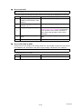
1.3
Service Information
Model
HL-5440D
HL-5450DN HL-5450DNT HL-5470DW HL-5470DWT
Machine life
300,000 pages (A4/Letter size) or 5 years
MTBF
4,000 hours
MTTR
0.5 hours
Maximum monthly volume
Up to 50,000 pages
Periodical
Fuser Unit
100,000 pages
maintenance Laser Unit
100,000 pages
parts
Paper Feeding 100,000 pages
Kit 1
Paper Feeding 100,000 pages
Kit 2
MP Paper
Feeding Kit
50,000 pages
Specifications are subject to change without notice.
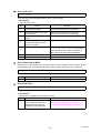
Model
HL-6180DW
HL-6180DWT
Machine life
300,000 pages (A4/Letter size) or 5 years
MTBF
4,000 hours
MTTR
0.5 hours
Maximum monthly volume
Up to 100,000 pages
Fuser Unit
100,000 pages
Periodical
maintenance Laser Unit
100,000 pages
parts
Paper Feeding 100,000 pages
Kit 1
Paper Feeding 100,000 pages
Kit 2
MP Paper
Feeding Kit
50,000 pages
Specifications are subject to change without notice.
1-6
Confidential
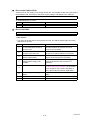
1.4
Supplies
Model
Toner
Starter
cartridge Toner *1
HL-5440D
Approximately
3,000 pages
(for U.S.A.,
Asia, China)
2,000 pages
(for Europe,
Oceania)
HL-5450DN HL-5450DNT HL-5470DW HL-5470DWT
Approximately Approximately 3,000 pages
3,000 pages
(for U.S.A.,
Europe, Asia,
China)
2,000 pages
(for Oceania)
Standard
Toner
Approximately 3,000 pages
High Yield
Toner
Approximately 8,000 pages
Super High
Yield Toner
Approximately 12,000
pages (for China)
N/A
Approximately N/A
12,000 pages
(for Asia)
When printing A4/Letter size one sided pages in accordance with ISO/IEC 19752.
Shelf life: 2 years without opening (6 months after opening)
Drum unit
Life expectancy: Approximately 30,000 pages/drum unit
The life expectancy varies according to the use condition.
Shelf life: 2 years
The shelf life of toner cartridge and drum unit is guaranteed under the normal condition as below;
(Temperature) Normal condition: 0 to 40°C
* Storage condition at the temperature of 40 to 50°C: Up to 5 days
* Storage condition at the temperature of -20 to 0°C: Up to 5 days
(Humidity) Normal condition: 35 to 85% (without condensation)
* Storage condition at the humidity of 85 to 95%: Up to 5 days (without condensation)
* Storage condition at the humidity of 10 to 35%: Up to 5 days (without condensation)
*1 Toner supplied with the machine.
Specifications are subject to change without notice.
1-7
Confidential
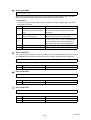
Model
Toner
Starter
cartridge Toner *1
HL-6180DW
HL-6180DWT
Approximately 3,000 pages (except for Europe)
8,000 pages (for Europe)
Standard
Toner
Approximately 3,000 pages
High Yield
Toner
Approximately 8,000 pages
Super High
Yield Toner
Approximately 12,000 pages
When printing A4/Letter size one sided pages in accordance with ISO/IEC 19752.
Shelf life: 2 years without opening (6 months after opening)
Drum unit
Life expectancy: Approximately 30,000 pages/drum unit
The life expectancy varies according to the use condition.
Shelf life: 2 years
The shelf life of toner cartridge and drum unit is guaranteed under the normal condition as below;
(Temperature) Normal condition: 0 to 40°C
* Storage condition at the temperature of 40 to 50°C: Up to 5 days
* Storage condition at the temperature of -20 to 0°C: Up to 5 days
(Humidity) Normal condition: 35 to 85% (without condensation)
* Storage condition at the humidity of 85 to 95%: Up to 5 days (without condensation)
* Storage condition at the humidity of 10 to 35%: Up to 5 days (without condensation)
*1 Toner supplied with the machine.
Specifications are subject to change without notice.
1-8
Confidential
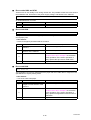
1.5
Paper
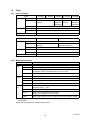
1.5.1 Paper handling
Model
Paper Input
HL-5440D
HL-5450DN HL-5450DNT HL-5470DW HL-5470DWT
Paper tray 1
250 sheets
Paper tray 2
500 sheets
(Option)
MP tray
50 sheets
Paper Output Face-down
Face-up
500 sheets 500 sheets 500 sheets
(Standard (Option)
(Standard
equipment)
equipment)
150 sheets (80 g/m2)
1 sheet (straight paper path)
Duplex
Yes
Specifications are subject to change without notice.
Model
Paper Input
HL-6180DW
Paper tray 1
500 sheets
Paper tray 2
500 sheets
(Option)
MP tray
50 sheets
Paper Output Face-down
Face-up
Duplex
HL-6180DWT
500 sheets
(Standard equipment)
150 sheets (80 g/m2)
1 sheet (straight paper path)
Yes
Specifications are subject to change without notice.
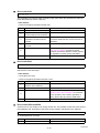
1.5.2 Media specifications
Model
Paper
Input
Media
weight
Media
size
All models
Paper tray 1
Plain Paper, Thin Paper, Recycled Paper
Paper tray 2
Plain Paper, Thin Paper, Recycled Paper
MP tray
Plain Paper, Thin Paper, Thick Paper, Thicker Paper, Recycled Paper,
Bond paper, Labels, Envelopes, Env. Thin, Env. Thick
Duplex
Plain Paper, Thin Paper, Recycled Paper
Paper tray 1
60 to 105 g/m2 (16 to 28 lb)
Paper tray 2
60 to 105 g/m2 (16 to 28 lb)
MP tray
60 to 163 g/m2 (16 to 43 lb)
Duplex
60 to 105 g/m2 (16 to 28 lb)
Paper tray 1
A4, Letter, B5 (ISO/JIS), A5, A5 (Long Edge), B6 (ISO), A6,
Executive, Legal *1, Folio
Paper tray 2
A4, Letter, B5 (ISO/JIS), A5, B6 (ISO), Executive, Legal *1, Folio
MP tray
Width: 76.2 to 215.9 mm (3 to 8.5 inch),
Length: 127 to 355.6 mm (5 to 14 inch)
Duplex
Letter, Legal, Folio (for U.S.A.) A4 (for Europe, Asia, Oceania, China)
*1 Legal size paper and Folio size paper are not available in some regions outside the USA
and Canada.
Specifications are subject to change without notice.
1-9
Confidential
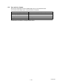
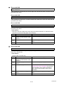
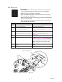
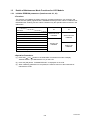
1.5.3 Type and size of paper
The printer loads paper from the installed paper tray or the manual feed slot.
The names for the paper trays in the printer driver as follows:
The name for the paper trays
The name for the paper trays in the printer driver
Paper tray 1 (T1)
Tray 1
Paper tray 2 (T2)
Tray 2
MP tray
MP Tray
Duplex
DX
Specifications are subject to change without notice.
1-10
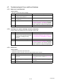
Confidential
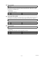
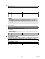
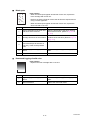
1.6
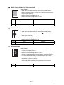
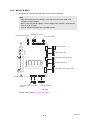
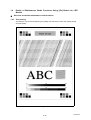
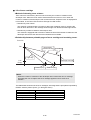
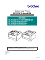
Printable Area
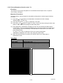
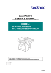
The figure below shows maximum unprintable areas.
The unprintable areas may vary depending on the paper size or settings in the application
you are using.
1
2
4
3
Usage
Print
Document Size
Top (1)
Bottom (3)
Left (2)
Right (4)
Letter
4.23 mm (0.16 inch)
6.35 mm (0.25 inch)
A4
4.23 mm (0.16 inch)
6.01 mm (0.24 inch)
Specifications are subject to change without notice.
1-11
Confidential
CHAPTER 2
TROUBLESHOOTING
Confidential
CHAPTER 2 TROUBLESHOOTING
This chapter details error messages and codes which the incorporated self-diagnostic
function of the machine will display if any error or malfunction occurs. If any error message
appears, refer to this chapter to find which parts should be checked or replaced.
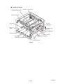
The latter half of this chapter provides sample problems which could occur in the main
sections of the machine and related troubleshooting procedures. These will help service
personnel identify and repair other similar defective sections.
CONTENTS
1. INTRODUCTION ........................................................................................................... 2-1
1.1 Precautions............................................................................................................ 2-1
1.2 Checks before Commencing Troubleshooting....................................................... 2-2
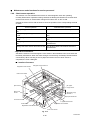
2. OVERVIEW ................................................................................................................... 2-4
2.1 Cross-section Drawing .......................................................................................... 2-4
2.2 Paper Feeding ....................................................................................................... 2-5
2.3 Operation of Each Part .......................................................................................... 2-6
2.4 Block Diagram ....................................................................................................... 2-8
2.5 Main Components ................................................................................................. 2-9
3. ERROR INDICATIONS................................................................................................ 2-10
3.1 Error Codes ......................................................................................................... 2-10
3.2 Error Messages ................................................................................................... 2-16
3.3 LED Display (LED Model).................................................................................... 2-19
3.3.1 LED display when operator call occurs .................................................... 2-19
3.3.2 LED display when service call occurs ...................................................... 2-23
4. TROUBLESHOOTING ................................................................................................ 2-28
4.1 Error Cause and Remedy.................................................................................... 2-28
4.2 Troubleshooting for Paper Feeding Problems ..................................................... 2-57
4.2.1 Multiple sheets of paper are fed ............................................................... 2-57
4.2.2 Paper becomes wrinkled .......................................................................... 2-57
4.2.3 Paper is fed at an angle ........................................................................... 2-57
4.2.4 Duplex printing is not possible.................................................................. 2-58
4.2.5 Paper is curled ......................................................................................... 2-58
4.2.6 Only single surface is printed in duplex printing mode ............................. 2-58
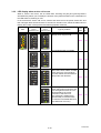
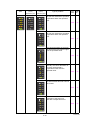
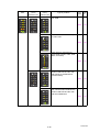
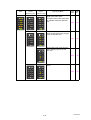
4.3 Troubleshooting for Image Defects...................................................................... 2-59
4.3.1 Image defect examples ............................................................................ 2-59
4.3.2 Troubleshooting according to image defect ............................................. 2-60
4.4 Troubleshooting for Software Problems .............................................................. 2-73
4.4.1 Cannot print data...................................................................................... 2-73
4.5 Troubleshooting for Network Problems ............................................................... 2-74
4.5.1 Cannot print via network connection ........................................................ 2-74
4.5.2 Cannot connect to access point ............................................................... 2-74
Confidential
4.6 Troubleshooting for Control Panel Problems....................................................... 2-75
4.6.1 Nothing is displayed on the LCD .............................................................. 2-75
4.6.2 LEDs are not activated ............................................................................. 2-75
4.6.3 Control panel is inoperable....................................................................... 2-75
4.7 Troubleshooting for Toner and Drum Problems................................................... 2-76
4.7.1 New toner is not detected......................................................................... 2-76
4.7.2 Cartridge error (toner cartridge cannot be detected)................................ 2-76
4.7.3 Drum error ................................................................................................ 2-76
4.8 Troubleshooting for Fuser Unit Problems ............................................................ 2-77
4.8.1 Fuser unit failure....................................................................................... 2-77
4.9 Troubleshooting for Laser Unit Problems ............................................................ 2-78
4.9.1 Laser unit failure....................................................................................... 2-78
4.10 Troubleshooting for PCB Problems ..................................................................... 2-79
4.10.1 Main PCB failure ...................................................................................... 2-79
4.10.2 High-voltage power supply PCB failure.................................................... 2-79
4.10.3 Low-voltage power supply PCB failure..................................................... 2-79
4.11 Troubleshooting for Other Problems.................................................................... 2-80
4.11.1 Machine is not turned ON......................................................................... 2-80
4.11.2 Main fan does not rotate........................................................................... 2-80
4.11.3 Main motor failure..................................................................................... 2-80
4.11.4 Unusual noise is generated from the machine ......................................... 2-80
Confidential
1. INTRODUCTION
Troubleshooting is a collection of solution procedures that service personnel should follow if
an error or malfunction occurs in the machine. It is difficult to determine troubleshooting
procedures for all possible problems that may occur in the future. Therefore, this chapter
describes typical problem cases and recovery procedures for these. These will help service
personnel identify and repair other similar defective sections.
1.1
Precautions
Be sure to observe the following precautions to prevent any secondary problems occurring
during troubleshooting:
(1) Be sure to unplug the AC cord before removing any covers or PCBs, adjusting the
machine, or conducting continuity tests using a tester.
(2) Do not hold the cable when connecting or disconnecting the cable. Be sure to hold the
connector.
(3) Static electricity generated and stored on your body may damage electronic parts.
Before handling the PCBs, touch a metal section of the machine to discharge static
electricity.
When transporting PCBs, be sure to wrap them in conductive sheets.
When replacing the PCBs, wear a grounding wrist band and perform replacement on a
conductive mat. Also take care not to touch the conductor sections on the flat cables.
(4) Be sure to always observe all warnings.
WARNING
Hazard labels as shown below are attached to the machine. Fully understand
the descriptions on the hazard labels and observe them during troubleshooting.
Take extreme care not to remove or damage the hazard labels.
WARNING
DO NOT use any flammable spray or flammable solvent such as alcohol, benzine,
or thinner in or around the machine. Otherwise a fire or electric shock may result.
(5) After repair is completed, check that the repaired sections, including those removed
once and then remounted, operate normally.
2-1
Confidential
1.2
Checks before Commencing Troubleshooting
Check the following items before commencing repairs on the machine.
Operating environment
(1) The machine is placed on a flat, stable surface.
(2) The machine is used in a clean environment where the temperature is between 10°C
(50°F) and 32.5°C (90.5°F) and the relative humidity is maintained between 20% and
80%.
(3) The machine is not exposed to direct sunlight, excessive heat, moisture, or dust.
(4) Hold the machine level while moving it.
Power supply
(1) Power described on the rating label attached on the machine is supplied. Power
fluctuation should be within ±10% of the rated voltage.
(2) The AC input power supply is within the regulated value.
(3) The cables and harnesses are connected correctly.
(4) The fuses are not blown.
Paper
(1) The recommended type of paper is being used. (Refer to "1.5.2 Media specifications" in
Chapter 1.)
(2) The paper is not damp.
(3) Short-grained paper or acid paper is not used.
Consumable parts
(1) The drum unit (including the toner cartridge) is set correctly.
2-2
Confidential
Others
(1) Condensation
When the machine is moved to a warm room from a cold location, condensation may
occur inside the machine, causing various problems as listed below.
• Condensation on the surface of optical devices such as the lens, reflecting mirror and
protection glass may cause light print image.
• If the exposure drum is cold, the electrical resistance of the photosensitive layer is
increased, making it impossible to obtain the correct print density.
• Condensation on the charge unit may cause corona charge leakage.
• Condensation on the plate or separation pad may cause paper feed problems.
If condensation has formed in the machine, leave the machine for at least two hours until
it reaches room temperature.
If the drum unit is unpacked soon after it is moved to a warm room from a cold location,
condensation may occur inside the unit which may cause printing failure. Leave the
drum unit for one or two hours until it reaches room temperature, and then unpack it.
(2) Low temperature
The motor may not operate normally under a low temperature environment because too
much load is applied to each drive. In this case, increase the room temperature.
Cleaning
Use a soft lint-free cloth.
WARNING
DO NOT use any flammable spray or flammable solvent such as alcohol, benzine,
or thinner to clean the machine. DO NOT use these articles near the machine.
2-3
Confidential
2. OVERVIEW
2.1
Cross-section Drawing
Heat unit
<Back side>
Fuser unit
Laser unit
Eject roller 2
Eject pinch roller
Developer roller
Exposure drum
<Front side>
Registration rear actuator
Registration front actuator
Registration roller
MP tray
Back cover
Front cover
Outer chute
MP separation roller
MP pick-up roller
Eject roller 1
MP paper empty actuator 1/2
Fuser cover
MP separation pad
Eject actuator
Pressure roller
T1 paper dust cleaning roller
T1 paper feed actuator
Duplex tray
T1 separation roller
T1 separation pad
Paper tray 1
T1 pick-up roller
T2 paper dust cleaning roller
Duplex paper feed roller
T2 paper feed actuator
Paper tray 2
T2 separation roller
Plate
T2 separation pad
T2 pick-up roller
Fig. 2-1
2-4
Confidential
2.2
Paper Feeding
<Back side>
<Front side>
Manual feed slot path
Duplex path
Paper tray 1 path
Paper tray 2 path
Fig. 2-2
2-5
Confidential
2.3
Operation of Each Part
Part name
Operation
T1 pick-up roller
Picks up the paper from paper tray 1.
T1 separation roller /
T1 separation pad
Separates the paper fed from paper tray 1 into single sheets.
T1 paper feed actuator
(T1 paper feed sensor)
Detects paper tray 1.
Detects a paper jam at the front section of the machine.
Detects the rear edge of the paper to determine the feed timing
of the next sheet of paper.
Registration front actuator
(Registration front sensor)
Detects the front edge of the paper to control the registration
roller drive.
Detects a paper jam at the front section of the machine.
Registration roller
Corrects the paper alignment when the paper makes contact
with the stopped registration roller. Feeds the paper after
correction.
Registration rear actuator
(Registration rear sensor)
Detects the front edge of the paper to adjust the writing start
position.
Detects a paper jam at the center section of the machine.
Detects the front and rear edges of the paper to determine the
paper size.
Heat unit
Pressure roller
Fuses the toner transferred to the paper by heat and pressure,
and feeds the paper to the eject roller.
Eject actuator
(Eject sensor)
Determines whether the paper is ejected from the fuser unit.
Detects the rear edge of the paper in duplex printing mode to
adjust the eject roller change timing.
Detects a paper jam at the rear section of the machine.
Determines whether the fuser cover is open when the back
cover is open.
Eject roller 1
Feeds the paper ejected from the fuser unit to eject roller 2.
Eject roller 2
Feeds the paper ejected from eject roller 1 to the output tray.
In duplex printing mode, rotates conversely after the paper is
fed a short distance to feed the paper to the duplex tray.
Duplex paper feed roller
Feeds the paper passing through the duplex tray to the
registration roller.
MP pick-up roller
Picks up the paper from the MP tray.
MP separation roller /
MP separation pad
Separates the paper fed from the MP tray into single sheets.
MP paper empty actuator 1/2 Detects the paper in the MP tray.
(MP paper empty sensor)
T2 pick-up roller
Picks up the paper from paper tray 2.
T2 separation roller /
T2 separation pad
Separates the paper fed from paper tray 2 into single sheets.
T2 paper feed actuator
(T2 paper feed sensor)
Detects paper tray 2.
Detects a paper jam at the front section of paper tray 2.
Determines whether the paper was fed.
Back cover sensor
Detects open back cover or incorrect setting of the duplex tray.
(Cannot determine which case applies.)
Front cover sensor
Detects open front cover.
T2 connect sensor
Detects connection of paper tray 2.
2-6
Confidential
Part name
Operation
Toner sensor
Detects the toner remaining in the cartridge. When the toner is
below the specified level, the user is notified that the toner
cartridge needs replacing soon.
New toner sensor
Detects the toner volume when a new toner cartridge is set.
(Does not react to the starter toner cartridge even if it is new.)
When a new toner cartridge is detected, the developer roller
counter and the developing bias voltage value are reset, and
the toner cartridge replacement counter increases by one.
2-7
Confidential
2.4
Block Diagram
Panel PCB
(LED)
(Wireless LAN model only)
Panel PCB
(LCD)
Wireless LAN
Backlight
PCB
LCD
MP-PE sensor PCB
Fuser unit
HVPS PCB
Center thermistor
Side thermistor
Eject sensor
PCB
T1 paper feed sensor PCB
Registration front/rear sensor PCB
Back cover
sensor
Halogen-heater
LVPS PCB
Power switch
Duplex
solenoid
Relay front
PCB
Toner sensor PCB
Toner sensor
Front cover sensor
Develop clutch
DIMM
MP solenoid
T1 clutch
New toner
sensor
USB
function
Registration clutch
Laser unit
Main motor
Toner LED
PCB
Toner sensor
LT
connector
Main fan
T2 paper feed sensor PCB
T2 relay PCB
T2 clutch
Main PCB
Fig. 2-3
2-8
Confidential
2.5
Main Components
Paper stack levers
Paper stack levers
Panel printed ASSY
Top cover ASSY
LCD
Top cover ASSY
LCD holder
SW key printed ASSY
Panel light guide
Panel light guide
Rubber key printed ASSY
Backlight
PCB ASSY
Panel PCB ASSY
Panel PCB
ASSY
Back cover
Air duct
Side cover R
Main fan
Outer chute
Laser unit
Low-voltage power
supply PCB ASSY
Fuser cover
Duplex tray
Fuser unit
Fuser drive gear 39
Front cover ASSY
Main PCB ASSY
Develop one
way clutch 53
High-voltage power
supply PCB ASSY
Develop joint
Relay front PCB ASSY
Develop clutch 51R
MP paper
guide ASSY
LT connector (T1)
Develop joint gear 37
Main motor
Toner sensor PCB ASSY
T1 clutch
MP cover
ASSY
Registration clutch
Paper tray 1
Side cover L
Fig. 2-4
2-9
Confidential
3. ERROR INDICATIONS
This machine includes a self-diagnosis function. If the machine does not work normally it
judges that an error has occurred, and indicates the corresponding error message on the
LCD, which in turn helps the service men to quickly find out the problem.
3.1
Error Codes
The errors with a mesh background in the table below do not occur in the normal operation.
They might occur due to noise around the installation site, change of the power supply
voltage, and failures in the software.
Error
codes
Refer
to:
Error
codes
2-28
2900 An unidentified error occurred.
2-30
2-28 2A00 An unidentified error occurred.
2-30
2-28 2B00 An unidentified error occurred.
2-30
2-29 2C00 An unidentified error occurred.
2-30
2-29 2D00 An unidentified error occurred.
2-30
2-29 2E00 An unidentified error occurred.
2-30
1100 An unidentified error occurred.
2-29 2F00 An unidentified error occurred.
2-30
1200 An unidentified error occurred.
2-29
3000 An unidentified error occurred.
2-30
1600 An unidentified error occurred.
2-29
3100 An unidentified error occurred.
2-30
1700 An unidentified error occurred.
2-29
3200 An unidentified error occurred.
2-30
1800 An unidentified error occurred.
2-29
3300 An unidentified error occurred.
2-30
1900 An unidentified error occurred.
2-29
3400 An unidentified error occurred.
2-30
1A00 An unidentified error occurred.
2-29
2-30
1B00 An unidentified error occurred.
2-29
1C00 An unidentified error occurred.
2-29
3500 An unidentified error occurred.
An error occurred in the high3600
voltage power supply PCB.
3700 An unidentified error occurred.
Problem
0B00 An unidentified error occurred.
0C01
0C02
Log registration failed.
0C03
0C04
Data cannot be saved because
0D00 storage data area in the memory
is full.
0E00 An unidentified error occurred.
The back cover sensor detected
0F00 that the cover was open in
duplex printing mode.
1000 An unidentified error occurred.
Refer
to:
Problem
2-30
2-30
1D00 An unidentified error occurred.
2-29 3800 An unidentified error occurred.
The number of rotations of the
1E00
2-30 3900 An unidentified error occurred.
drum unit is reaching the life limit.
1F00 An unidentified error occurred.
2-30 3A00 An unidentified error occurred.
An error occurred during access
2000 An unidentified error occurred.
2-30 3B00
to the DRAM in the main PCB.
2100 An unidentified error occurred.
2-30 3C00 An unidentified error occurred.
2-30
2200 An unidentified error occurred.
2-30 3D00 An unidentified error occurred.
2-31
2300 An unidentified error occurred.
2-30 3E00 An unidentified error occurred.
2-31
2400 An unidentified error occurred.
2-30 3F00 An unidentified error occurred.
2-31
2500 An unidentified error occurred.
2-30
4000 An unidentified error occurred.
2-31
2600 An unidentified error occurred.
2-30
4200 An unidentified error occurred.
2-31
2700 An unidentified error occurred.
2-30
2-31
2800 An unidentified error occurred.
2-30
4300 An unidentified error occurred.
The toner sensor detected that
4400
the toner cartridge was not set.
2-10
2-30
2-30
2-31
2-31
2-31
Confidential
Error
codes
Problem
Refer
to:
Error
codes
Refer
to:
Problem
4500 An unidentified error occurred.
2-31 5B00 An unidentified error occurred.
2-35
4600 An unidentified error occurred.
2-31 5C00 An unidentified error occurred.
2-35
4700 An unidentified error occurred.
2-31 5D00 An unidentified error occurred.
2-35
4800 An unidentified error occurred.
2-31 5E00 An unidentified error occurred.
2-35
4900 An unidentified error occurred.
2-31 5F00 An unidentified error occurred.
2-35
4A00 An unidentified error occurred.
2-31
6000 An unidentified error occurred.
2-35
4B00 An unidentified error occurred.
2-31
6100 An unidentified error occurred.
2-35
4C00 An unidentified error occurred.
2-31
4D00 An unidentified error occurred.
2-31
4E00 An unidentified error occurred.
2-31
6200 An unidentified error occurred.
2-35
The toner sensor detected no
toner remaining or the number of
6300
2-36
rotations of the developer roller
has reached the upper limit.
6400 An unidentified error occurred.
2-36
4F00 An unidentified error occurred.
The number of rotations of the
5000 drum unit has reached the life
limit. (Printing does not stop.)
2-31
6500 An unidentified error occurred.
2-36
2-32
6600 An unidentified error occurred.
2-36
Printable pages set for the MP
5100 paper feeding kit have reached 2-32
the limit. (Printing does not stop.)
The toner sensor detected that
the toner remaining has fallen
6700 below the specified level or the
developer roller counter has
exceeded the specified value.
2-36
2-32
6800 An unidentified error occurred.
2-36
2-32
6900 An unidentified error occurred.
2-36
Printable pages set for paper
5200 feeding kit 1 have reached the
limit. (Printing does not stop.)
Printable pages set for paper
5300 feeding kit 2 have reached the
limit. (Printing does not stop.)
Printable pages set for the fuser
5400 unit have reached the limit.
(Printing does not stop.)
Printable pages set for the laser
5500 unit have reached the limit.
(Printing does not stop.)
5600
5700
5800
5900
5A00
The center thermistor of the fuser unit
2-32 6A00 has not reached the specified
temperature within the specified time.
The center thermistor of the fuser unit
2-33 6B00 has not reached the specified
temperature within the specified time.
The center thermistor of the
The eject sensor detected that
fuser unit detected a
2-33 6C00
the fuser cover was open.
temperature higher than the
specified value.
The registration front sensor
After the heat unit was heated
does not detect paper pass
normally, the center thermistor of
within the specified time after the 2-34 6D00 the fuser unit detected a
first side was printed in duplex
temperature lower than the
printing mode.
specified value.
Any of error codes 6A00 to 6F00,
7600, 7800, DD00,DE00, or E200
The center thermistor of the
(fuser unit error) occurred when
2-35 6E00 fuser unit detected that the heat
the power switch was turned ON
unit was not heated.
or sleep mode was released.
Rechecking the error after the power
switch was turned OFF and then ON
again because an error was detected
The center thermistor or the side
by the center thermistor of the fuser
2-35 6F00 thermistor of the fuser unit
unit. (This message is displayed for
detected a temperature error.
approximately 15 minutes when the
machine is restarted after error code
5800 has occurred.)
An unidentified error occurred.
2-35 7000 An unidentified error occurred.
2-11
2-37
2-37
2-37
2-37
2-37
2-37
2-38
Confidential
Error
codes
Problem
Refer
to:
Detected an error in the
7100 synchronized signal of the
2-38
polygon motor for the laser unit.
Error
codes
Refer
to:
Problem
Cannot detect the signal from
7200 the beam detecting sensor for
the laser unit.
2-38
7300 An unidentified error occurred.
2-38
7400 An unidentified error occurred.
The side thermistor of the fuser
7500 unit detected a temperature
higher than the specified value.
The center thermistor of the
fuser unit detected a
7600 temperature rise greater than the
specified value within the
specified time.
The center thermistor of the
fuser unit detected a
7800 temperature fall greater than the
specified value within the
specified time.
Cannot detect the synchronized
signal of the main motor.
7A00 The speed of the main motor
does not stabilize within the
specified time.
2-38
Detected discharge when the
8300 number of rotations of the drum
has exceeded twice the life limit.
The eject sensor remains ON
(paper pass detected) for more
8400 than the specified time even
after the registration rear sensor
detected the end of paper pass.
The T1 paper feed sensor
8500 detected that paper tray 1 was
not set.
8600 An unidentified error occurred.
2-38
8700 An unidentified error occurred.
2-39
The eject sensor does not detect
paper pass after the registration
8800
2-42
rear sensor detected the end of
paper pass.
7B00 An unidentified error occurred.
2-40 8B00
7C00 An unidentified error occurred.
2-40 8C00
2-39
8900
2-39 8A00
Detected discharge that may be
7D00 attributable to dirty corona wire 2-40 8D00
on the drum unit.
The registration front sensor
detected that the paper fed was
smaller than or larger than the
specified size in duplex printing
mode.
The registration front sensor
does not detect paper pass
within the specified time after the
T1 paper feed sensor detected
paper pass.
The registration front sensor
does not detect paper pass
within the specified time after the
T2 paper feed sensor detected
paper pass.
The registration front sensor
does not detect paper pass
within the specified time after the
paper was picked up from the
MP tray.
When the power switch was
turned ON, the eject sensor
detected paper pass or detected
that the fuser cover was open.
An unidentified error occurred.
7E00 An unidentified error occurred.
2-40 8E00
7F00 An unidentified error occurred.
2-40 8F00 An unidentified error occurred.
When printing from the MP tray,
the size of paper set in the MP
2-40 9000
tray does not match the size
specified by the driver.
When printing from paper tray 1,
the size of paper set in paper
2-40 9100
tray 1 does not match the size
specified by the driver.
When printing from paper tray 2,
the size of paper set in paper
2-40 9200
tray 2 does not match the size
specified by the driver.
8000 An unidentified error occurred.
8100 An unidentified error occurred.
8200 An unidentified error occurred.
2-12
2-40
2-41
2-41
2-42
2-42
2-42
2-43
2-43
2-44
2-44
2-44
2-44
2-45
2-45
2-45
Confidential
Error
codes
9300
Problem
When printing from the MP tray,
the MP paper empty sensor
detected that there was no paper
set in the MP tray.
When printing from paper tray 1,
the T1 paper feed sensor
detected that there was no paper
set in paper tray 1.
When printing from paper tray 2,
the T2 paper feed sensor
detected that there was no paper
set in paper tray 2.
When printing with the tray
designation set to AUTO, the MP
paper empty sensor, T1 paper
feed sensor and T2 paper feed
sensor all detected that there
was no paper set in the MP tray,
paper tray 1 and paper tray 2.
An unidentified error occurred.
Refer
to:
Error
codes
Refer
to:
Problem
2-45 AB00 An unidentified error occurred.
2-49
2-46 AC00 An unidentified error occurred.
2-49
2-46 AD00 An unidentified error occurred.
2-49
2-47 AE00 An unidentified error occurred.
2-49
2-47 AF00 An unidentified error occurred.
2-49
9800 An unidentified error occurred.
Printing on a paper size not
9900 supported for duplex printing
was attempted from the driver.
There is no paper set in the MP
9A00 tray when feeding from the MP
tray is designated from the driver.
9B00 An unidentified error occurred.
2-47 B000 An unidentified error occurred.
2-49
2-47 B100 An unidentified error occurred.
2-49
2-48 B200 An unidentified error occurred.
2-49
2-48 B300 An unidentified error occurred.
2-49
9C00 An unidentified error occurred.
2-48 B400 An unidentified error occurred.
2-49
9D00 An unidentified error occurred.
2-48 B500 An unidentified error occurred.
2-49
9E00 An unidentified error occurred.
2-48 B600 An unidentified error occurred.
2-49
9F00 An unidentified error occurred.
2-48 B700 An unidentified error occurred.
2-49
A000 An unidentified error occurred.
2-48 B800 An unidentified error occurred.
The front cover sensor detected
A100
2-49 B900 An unidentified error occurred.
that the front cover was open.
A200 An unidentified error occurred.
2-49 BA00 An unidentified error occurred.
2-49
A300 An unidentified error occurred.
2-49 BB00 An unidentified error occurred.
2-49
A400 An unidentified error occurred.
2-49 BC00 An unidentified error occurred.
2-49
A500 An unidentified error occurred.
2-49 BD00 An unidentified error occurred.
2-49
A600 An unidentified error occurred.
2-49 BE00 An unidentified error occurred.
2-49
A700 An unidentified error occurred.
A900 An unidentified error occurred.
2-49 BF00 An unidentified error occurred.
2-49
The new toner sensor could not
2-49 C000 detect the new toner cartridge
2-49
correctly.
2-49 C100 An unidentified error occurred.
2-50
AA00 An unidentified error occurred.
2-49 C200 An unidentified error occurred.
9400
9500
9600
9700
A800 An unidentified error occurred.
2-13
2-49
2-49
2-50
Confidential
Error
codes
Problem
C300 An unidentified error occurred.
C400 An unidentified error occurred.
C500 An unidentified error occurred.
C600 An unidentified error occurred.
C700
There is insufficient memory to
expand PC-print data.
Refer
to:
Error
codes
Refer
to:
Problem
Fuser unit error (except error
2-50 DD00 codes 6A00 to 6F00, 7600,
7800, DE00, and E200)
When the center thermistor of
the fuser unit is higher than the
idle temperature, the side
2-50 DE00
thermistor detected a
temperature lower than the
specified temperature.
2-50 DF00 An unidentified error occurred.
An error occurred in the ROM
2-50 E000
check sum.
2-51
2-52
2-52
2-52
2-50 E100 Program error
2-52
When the center thermistor of
the fuser unit is higher than the
idle temperature, the side
2-50 E200
thermistor detected a
temperature higher than the
specified temperature.
2-53
C900
2-50 E300 An unidentified error occurred.
2-53
2-53
CB00 An unidentified error occurred.
CC00 An unidentified error occurred.
2-51 E400 An unidentified error occurred.
Write error in the EEPROM of
2-51 E600
the main PCB
2-51 E700 An unidentified error occurred.
CD00 An unidentified error occurred.
2-51 E800 An unidentified error occurred.
2-54
CE00 An unidentified error occurred.
2-51 E900 An unidentified error occurred.
2-54
CF00 An unidentified error occurred.
2-51 EA00 An unidentified error occurred.
2-54
D000 An unidentified error occurred.
2-51 EB00 An unidentified error occurred.
2-54
D100 An unidentified error occurred.
2-54
D600 An unidentified error occurred.
2-51 EC00 Detected a main fan failure.
Communication between the
wireless LAN PCB and the main
2-51 ED00
PCB cannot be established at
machine startup.
Detected communication failure
after communication between
2-51 EE00
the wireless LAN PCB and the
main PCB was established.
2-51 EF00 The supplied power is unstable.
Malfunction of the flash memory
2-51 F000
on the main PCB
2-51 F100 An unidentified error occurred.
D700 An unidentified error occurred.
2-51 F200 An unidentified error occurred.
2-55
D800 An unidentified error occurred.
2-51 F300 An unidentified error occurred.
2-55
D900 An unidentified error occurred.
2-51 F400 An unidentified error occurred.
2-55
DA00 An unidentified error occurred.
2-51 F500 An unidentified error occurred.
2-55
DB00 An unidentified error occurred.
2-51 F600 An unidentified error occurred.
2-55
DC00 An unidentified error occurred.
2-51 F800 An unidentified error occurred.
2-55
The memory size allotted for
C800 Secure Print was exceeded
when saving Secure Print data.
Detected that DIMM was faulty
or was mounted incorrectly.
CA00 An unidentified error occurred.
D200 An unidentified error occurred.
D300 An unidentified error occurred.
D400 An unidentified error occurred.
D500 An unidentified error occurred.
2-14
2-53
2-54
2-54
2-54
2-55
2-55
2-55
Confidential
Error
codes
Problem
Refer
to:
Error
codes
Refer
to:
Problem
The country code was not
entered correctly.
FA00 An unidentified error occurred.
2-56 FD00 An unidentified error occurred.
2-56
2-56 FE00 An unidentified error occurred.
2-56
FB00 An unidentified error occurred.
2-56 FF00 An unidentified error occurred.
2-56
FC00 An unidentified error occurred.
2-56
F900
2-15
Confidential
3.2
Error Messages
The error messages displayed on the LCD of the machine and their description are shown in
the table below.
Error Message
Access Denied
Cartridge Error
Connection Error
Connection Fail
Cooling Down
Cover is Open
DIMM Error
Drum End Soon
Drum Error
Drum Stop
Duplex Disabled
Fuser Error
Ignore Data
Jam Duplex
Jam Inside
Description
Failed to authenticate the print limit ID when
PC-print was executed.
The new toner sensor could not detect the new
toner cartridge correctly.
Multiple access points were found as a result
of the access point search.
Connection failed although the access point
was found as a result of the access point
search.
The side thermistor of the fuser unit detected a
temperature higher than the specified value.
The front cover sensor detected that the front
cover was open.
The eject sensor detected that the fuser cover
was open.
When the power switch was turned ON, the
eject sensor detected paper pass or detected
that the fuser cover was open.
Detected that DIMM was faulty or was
mounted incorrectly.
The number of rotations of the drum unit is
reaching the life limit.
Detected discharge that may be attributable to
dirty corona wire on the drum unit.
Detected discharge when the number of
rotations of the drum has exceeded twice the
life limit.
The back cover sensor detected that the cover
was open in duplex printing mode.
An error occurred in the fuser unit when the
power switch was turned ON or sleep mode
was released.
Detected undecodable data during printing.
Received undecodable PS data.
The registration front sensor does not detect
paper pass within the specified time after the
first side was printed in duplex printing mode.
The eject sensor does not detect paper pass
after the registration rear sensor detected the
end of paper pass.
2-16
Error
codes
Refer
to:
---
2-73
C000
2-49
---
2-74
---
2-74
7500
2-38
A100
2-49
5600
2-33
8D00
2-44
C900
2-50
1E00
2-30
7D00
2-40
8300
2-40
0F00
2-29
5800
5900
6A00
6B00
6C00
6D00
6E00
6F00
7600
7800
DD00
DE00
E200
2-35
2-35
2-37
2-37
2-37
2-37
2-37
2-37
2-39
2-39
2-51
2-52
2-53
---
2-73
5700
2-34
8800
2-42
Confidential
Error Message
Jam MP Tray
Jam Rear
Jam Tray 1
Jam Tray 2
Log Access Error
Description
The registration front sensor does not detect
paper pass within the specified time after the
paper was picked up from the MP tray.
The eject sensor remains ON (paper pass
detected) for more than the specified time
even after the registration rear sensor detected
the end of paper pass.
The registration front sensor does not detect
paper pass within the specified time after the
T1 paper feed sensor detected paper pass.
The registration front sensor does not detect
paper pass within the specified time after the
T2 paper feed sensor detected paper pass.
Log registration failed.
Machine Error F9
The country code was not entered correctly.
Manual Feed
There is no paper set in the MP tray when
feeding from the MP tray is designated from
the driver.
When printing from the MP tray, the MP paper
empty sensor detected that there was no
paper set in the MP tray.
When printing from paper tray 1, the T1 paper
feed sensor detected that there was no paper
set in paper tray 1.
When printing from paper tray 2, the T2 paper
feed sensor detected that there was no paper
set in paper tray 2.
When printing with the tray designation set to
AUTO, the MP paper empty sensor, T1 paper
feed sensor and T2 paper feed sensor all
detected that there was no paper set in the MP
tray, paper tray 1 and paper tray 2.
The toner sensor detected that the toner
cartridge was not set.
The T1 paper feed sensor detected that paper
tray 1 was not set.
There is insufficient memory to expand PCprint data.
The memory size allotted for Secure Print was
exceeded when saving Secure Print data.
The program cannot be updated due to
insufficient memory.
The number of rotations of the drum unit has
reached the life limit. (Printing does not stop.)
Printable pages set for the fuser unit have
reached the limit. (Printing does not stop.)
Printable pages set for the laser unit have
reached the limit. (Printing does not stop.)
Printable pages set for the MP paper feeding kit
have reached the limit. (Printing does not stop.)
Printable pages set for paper feeding kit 1 have
reached the limit. (Printing does not stop.)
Printable pages set for paper feeding kit 2 have
reached the limit. (Printing does not stop.)
No Paper
No Toner
No Tray
Out of Memory
Replace Drum
Replace Fuser
Replace Laser
Replace PF Kit MP
Replace PF Kit1
Replace PF Kit2
2-17
Error
codes
Refer
to:
8C00
2-44
8400
2-41
8A00
2-43
8B00
2-43
0C01
0C02
0C03
0C04
2-28
F900
2-56
9A00
2-48
9300
2-45
9400
2-46
9500
2-46
9600
2-47
4400
2-31
8500
2-41
C700
2-50
C800
2-50
---
2-79
5000
2-32
5400
2-32
5500
2-33
5100
2-32
5200
2-32
5300
2-32
Confidential
Error Message
Replace Toner
Self-Diagnostic
Size Error DX
Size Mismatch
Storage Full
Toner Low
Description
The toner sensor detected no toner remaining
or the number of rotations of the developer
roller has reached the upper limit.
Rechecking the error after the power switch
was turned OFF and then ON again because
an error was detected by the center thermistor
of the fuser unit.
(This message is displayed for approximately
15 minutes when the machine is restarted after
error code 5800 has occurred.)
The registration front sensor detected that the
paper fed was smaller than or larger than the
specified size in duplex printing mode.
Printing on a paper size not supported for
duplex printing was attempted from the driver.
When printing from the MP tray, the size of
paper set in the MP tray does not match the
size specified by the driver.
When printing from paper tray 1, the size of
paper set in paper tray 1 does not match the
size specified by the driver.
When printing from paper tray 2, the size of
paper set in paper tray 2 does not match the
size specified by the driver.
Data cannot be saved because storage data
area in the memory is full.
The toner sensor detected that the toner
remaining has fallen below the specified level
or the developer roller counter has exceeded
the specified value.
2-18
Error
codes
Refer
to:
6300
2-36
5900
2-35
8900
2-42
9900
2-47
9000
2-45
9100
2-45
9200
2-45
0D00
2-28
6700
2-36
Confidential
3.3
LED Display (LED Model)
3.3.1 LED display when operator call occurs
Determine the message details according to the LED display on the control panel. Refer to
the page shown in the "Refer to:" column in the table below to take appropriate measures.
Most errors are automatically cleared after measures are taken. If not automatically cleared,
press the [Go] button to reset the machine.
LED status in the table below:
LED
Unlit
Lit
Flashing
Error
codes
Refer
to:
Printable pages set for the MP paper feeding kit,
paper feeding kit 1, or paper feeding kit 2 have
reached the limit. (Printing does not stop.)
5100
5200
5300
2-32
2-32
2-32
Printable pages set for the fuser unit have reached
the limit. (Printing does not stop.)
5400
2-32
5500
2-33
6700
2-36
1E00
2-30
5000
2-32
Type of problem
Printable pages set for the laser unit have reached
the limit. (Printing does not stop.)
The toner sensor detected that the toner remaining
has fallen below the specified level or the developer
roller counter has exceeded the specified value.
The number of rotations of the drum unit is reaching
the life limit.
The number of rotations of the drum unit has
reached the life limit. (Printing does not stop.)
2-19
Confidential
LED
Type of problem
The side thermistor of the fuser unit detected a
temperature higher than the specified value.
Error
codes
Refer
to:
7500
2-38
-
-
A100
2-49
5600
2-33
0F00
2-29
4400
2-31
6300
2-36
C000
2-49
8300
2-40
Ready state under a low temperature environment.
The front cover sensor detected that the front cover
was open.
The eject sensor detected that the fuser cover was
open.
The back cover sensor detected that the cover was
open in duplex printing mode.
The toner sensor detected that the toner cartridge
was not set.
The toner sensor detected no toner remaining or the
number of rotations of the developer roller has
reached the upper limit.
The new toner sensor could not detect the new
toner cartridge correctly.
Detected discharge when the number of rotations of
the drum has exceeded twice the life limit.
2-20
Confidential
LED
Type of problem
When printing from the MP tray, paper tray 1, or
paper tray 2, the size of paper set in the MP tray,
paper tray 1 or paper tray 2 does not match the size
specified by the driver.
Printing on a paper size not supported for duplex
printing was attempted from the driver.
The T1 paper feed sensor detected that paper tray
1 was not set.
The eject sensor does not detect paper pass after
the registration rear sensor detected the end of
paper pass.
The registration front sensor detected that the paper
fed was smaller than or larger than the specified
size in duplex printing mode.
The registration front sensor does not detect paper
pass within the specified time after the T1 or T2
paper feed sensor detected paper pass.
The registration front sensor does not detect paper
pass within the specified time after the paper was
picked up from the MP tray.
When the power switch was turned ON, the eject
sensor detected paper pass or detected that the
fuser cover was open.
When printing with the tray designation set to
AUTO, the MP paper empty sensor, T1 paper feed
sensor and T2 paper feed sensor all detected that
there was no paper set in the MP tray, paper tray 1
and paper tray 2.
When printing from the MP tray, the MP paper
empty sensor detected that there was no paper set
in the MP tray.
When printing from paper tray 1 or 2, the T1 or T2
paper feed sensor detected that there was no paper
set in paper tray 1 or 2.
There is no paper set in the MP tray when feeding
from the MP tray is designated from the driver.
There is insufficient memory to expand PC-print
data.
Error
codes
Refer
to:
9000
9100
9200
2-45
2-45
2-45
9900
2-47
8500
2-41
8800
2-42
8900
2-42
8A00
8B00
2-43
2-43
8C00
2-44
8D00
2-44
9600
2-47
9300
2-45
9400
9500
2-46
2-46
9A00
2-48
C700
2-50
0C01
0C02
0C03
0C04
2-28
Log registration failed.
2-21
Confidential
Error
codes
Refer
to:
The registration front sensor does not detect paper
pass within the specified time after the first side was
printed in duplex printing mode.
5700
2-34
The eject sensor remains ON (paper pass detected)
for more than the specified time even after the
registration rear sensor detected the end of paper
pass.
8400
2-41
7D00
2-40
C900
2-50
3B00
2-31
E000
2-52
E100
2-52
LED
Type of problem
Detected discharge that may be attributable to dirty
corona wire on the drum unit.
Detected that DIMM was faulty or was mounted
incorrectly.
An error occurred during access to the DRAM in the
main PCB.
An error occurred in the ROM check sum.
Program error
2-22
Confidential
3.3.2 LED display when service call occurs
When a service call occurs, the six LEDs flash. Pressing the [Go] and [Cancel] buttons
simultaneously allows you to identify the location of the problem based on the combination of
the LED status: lit, flashing or unlit.
In the event that a service call occurs, instruct end users to turn the power switch OFF and
then ON again after several seconds. If the service call still occurs, follow the table below to
identity the location of the problem and take appropriate measures.
LED
Press [Go] and
Press [Go] and
[Cancel]
[Cancel]
simultaneously once simultaneously twice
Type of problem
Error Refer
codes to:
An error occurred in the highvoltage power supply PCB.
3600
2-30
The supplied power is unstable.
EF00 2-55
Any of error codes 6A00 to 6F00,
7600, 7800, DD00, DE00, or E200
(fuser unit error) occurred when
the power switch was turned ON or
sleep mode was released.
5800
Rechecking the error after the
power switch was turned OFF and
then ON again because an error
was detected by the center
thermistor of the fuser unit.
5900
(This message is displayed for
approximately 15 minutes when
the machine is restarted after error
code 5800 has occurred.)
2-23
2-35
2-35
Confidential
LED
Press [Go] and
Press [Go] and
[Cancel]
[Cancel]
simultaneously once simultaneously twice
Type of problem
Error Refer
codes to:
The center thermistor of the fuser
unit has not reached the specified
temperature within the specified
time.
6A00 2-37
The center thermistor of the fuser
unit has not reached the specified
temperature within the specified
time.
6B00 2-37
The center thermistor of the fuser
unit detected a temperature higher
than the specified value.
6C00 2-37
After the heat unit was heated
normally, the center thermistor of
the fuser unit detected a
temperature lower than the
specified value.
6D00 2-37
The center thermistor of the fuser
unit detected that the heat unit was
not heated.
6E00 2-37
The center thermistor or the side
thermistor of the fuser unit
detected a temperature error.
6F00 2-37
2-24
Confidential
LED
Press [Go] and
Press [Go] and
[Cancel]
[Cancel]
simultaneously once simultaneously twice
Type of problem
Error Refer
codes to:
The center thermistor of the fuser
unit detected a temperature rise
greater than the specified value
within the specified time.
7600
2-39
7800
2-39
The center thermistor of the fuser
unit detected a temperature fall
greater than the specified value
within the specified time.
Fuser unit error (except error
codes 6A00 to 6F00, 7600, 7800,
DE00, and E200)
DD00 2-51
When the center thermistor of the
fuser unit is higher than the idle
temperature, the side thermistor
detected a temperature lower than
the specified temperature.
When the center thermistor of the
fuser unit is higher than the idle
temperature, the side thermistor
detected a temperature higher
than the specified temperature.
2-25
DE00 2-52
E200 2-53
Confidential
LED
Press [Go] and
Press [Go] and
[Cancel]
[Cancel]
simultaneously once simultaneously twice
Type of problem
Error Refer
codes to:
Write error in the EEPROM of the
main PCB
E600 2-53
Malfunction of the flash memory on
the main PCB
F000 2-55
Fuser unit error (except error
codes 6A00 to 6F00, 7600, 7800,
DE00, and E200)
DD00 2-51
Communication between the
wireless LAN PCB and the main
PCB cannot be established at
machine startup.
ED00 2-54
Detected communication failure
after communication between the
wireless LAN PCB and the main
PCB was established.
EE00 2-54
2-26
Confidential
LED
Press [Go] and
Press [Go] and
[Cancel]
[Cancel]
simultaneously once simultaneously twice
Type of problem
Cannot detect the synchronized
signal of the main motor.
The speed of the main motor does
not stabilize within the specified
time.
Error Refer
codes to:
7A00 2-39
Detected an error in the
synchronized signal of the polygon
motor for the laser unit.
7100
2-38
7200
2-38
Cannot detect the signal from the
beam detecting sensor for the
laser unit.
The main PCB detected a main fan
failure.
EC00 2-54
2-27
Confidential
4. TROUBLESHOOTING
4.1
Error Cause and Remedy
Error code 0B00
This error does not usually occur during normal use. The possible causes are noise around
the installation site, fluctuation of the power supply voltage, and failures in the software.
--An unidentified error occurred.
Step
1
Cause
Main PCB failure
Remedy
Replace the main PCB ASSY.
Error code 0C01/0C02/0C03/0C04
Log Access Error.
Log registration failed.
<User Check>
• Follow the User's Guide to set the network again.
Step
1
Cause
Main PCB failure
Remedy
Replace the main PCB ASSY.
Error code 0D00
Storage Full
Data cannot be saved because storage data area in the memory is full.
<User Check>
• Print the Storage Print Data.
• Expand DIMM.
Step
1
Cause
Main PCB failure
Remedy
Replace the main PCB ASSY.
2-28
Confidential
Error code 0E00
This error does not usually occur during normal use. The possible causes are noise around
the installation site, fluctuation of the power supply voltage, and failures in the software.
--An unidentified error occurred.
Step
1
Cause
Remedy
Main PCB failure
Replace the main PCB ASSY.
Error code 0F00
Duplex Disabled
The back cover sensor detected that the cover was open in duplex printing mode.
<User Check>
• Close the back cover.
• Set the duplex tray.
Step
Cause
Remedy
1
Connection failure of the back
cover sensor harness
Check the connection of the back cover sensor
harness, and reconnect it if necessary.
2
Back cover sensor attachment
failure
Reattach the back cover sensor.
Broken rib (on the right inside
the back cover) where the back
cover switch is pressed
Replace the back cover.
3
4
Damaged duplex tray
Replace the duplex tray.
5
Back cover sensor failure
Replace the back cover switch harness ASSY.
6
Main PCB failure
Replace the main PCB ASSY.
Error codes 1000 to 1D00
These errors do not usually occur during normal use. The possible causes are noise around
the installation site, fluctuation of the power supply voltage, and failures in the software.
--An unidentified error occurred.
Step
1
Cause
Main PCB failure
Remedy
Replace the main PCB ASSY.
2-29
Confidential
Error code 1E00
Drum End Soon
The number of rotations of the drum unit is reaching the life limit.
Step
1
Cause
Replace the drum unit with a
new one and reset the drum
counter. If the error display is
not cleared, the main PCB is
faulty.
Remedy
Replace the main PCB ASSY.
Error codes 1F00 to 3500
These errors do not usually occur during normal use. The possible causes are noise around
the installation site, fluctuation of the power supply voltage, and failures in the software.
--An unidentified error occurred.
Step
1
Cause
Main PCB failure
Remedy
Replace the main PCB ASSY.
Error code 3600
Print Unable 36
An error occurred in the high-voltage power supply PCB.
Step
Cause
Remedy
1
High-voltage power supply PCB Replace the high-voltage power supply PCB
failure
ASSY.
2
Main PCB failure
Replace the main PCB ASSY.
Error codes 3700 to 3A00
These errors do not usually occur during normal use. The possible causes are noise around
the installation site, fluctuation of the power supply voltage, and failures in the software.
--An unidentified error occurred.
Step
1
Cause
Main PCB failure
Remedy
Replace the main PCB ASSY.
2-30
Confidential
Error code 3B00
Print Unable 3B
An error occurred during access to the DRAM in the main PCB.
Step
1
Cause
Main PCB failure
Remedy
Replace the main PCB ASSY.
Error codes 3C00 to 4300
These errors do not usually occur during normal use. The possible causes are noise around
the installation site, fluctuation of the power supply voltage, and failures in the software.
--An unidentified error occurred.
Step
1
Cause
Main PCB failure
Remedy
Replace the main PCB ASSY.
Error code 4400
No Toner
The toner sensor detected that the toner cartridge was not set.
<User Check>
• Set the toner cartridge.
Step
Cause
Toner sensor PCB failure
Refer to "1.3.8 Check sensor operation
(function code: 32)" in Chapter 5 to check the
sensor operation. If the sensor operation is
faulty, replace the toner sensor PCB ASSY.
2
Relay front PCB failure
Replace the relay front PCB ASSY.
3
Main PCB failure
Replace the main PCB ASSY.
1
Remedy
Error codes 4500 to 4F00
These errors do not usually occur during normal use. The possible causes are noise around
the installation site, fluctuation of the power supply voltage, and failures in the software.
--An unidentified error occurred.
Step
1
Cause
Main PCB failure
Remedy
Replace the main PCB ASSY.
2-31
Confidential
Error code 5000
Replace Drum
The number of rotations of the drum unit has reached the life limit. (Printing does not stop.)
<User Check>
• Prepare the drum unit.
Step
1
Cause
Replace the drum unit with a
new one and reset the drum
counter. If the error display is
not cleared, the main PCB is
faulty.
Remedy
Replace the main PCB ASSY.
Error code 5100
Replace PF KitMP
Printable pages set for the MP paper feeding kit have reached the limit. (Printing does not
stop.)
Error code 5200
Replace PF Kit1
Printable pages set for paper feeding kit 1 have reached the limit. (Printing does not stop.)
Error code 5300
Replace PF Kit2
Printable pages set for paper feeding kit 2 have reached the limit. (Printing does not stop.)
Step
Cause
Remedy
1
Abrasion of the MP paper
feeding kit, paper feeding kit 1
or paper feeding kit 2
Replace the MP paper feeding kit, paper
feeding kit 1 or paper feeding kit 2.
2
Main PCB failure
Replace the main PCB ASSY.
Error code 5400
Replace Fuser
Printable pages set for the fuser unit have reached the limit. (Printing does not stop.)
Step
Cause
Remedy
1
End of life of the fuser unit
Replace the fuser unit.
2
Main PCB failure
Replace the main PCB ASSY.
2-32
Confidential
Error code 5500
Replace Laser
Printable pages set for the laser unit have reached the limit. (Printing does not stop.)
Step
Cause
Remedy
1
End of life of the laser unit
Replace the laser unit.
2
Main PCB failure
Replace the main PCB ASSY.
Error code 5600
Cover is Open
The eject sensor detected that the fuser cover was open.
<User Check>
• Close the fuser cover.
Step
Cause
Remedy
1
Eject actuator attachment
failure
Reattach the eject actuator.
2
Eject actuator spring
attachment failure
Reattach the eject actuator spring.
3
Eject actuator and/or fuser
cover failure
Replace the fuser cover.
Eject sensor PCB failure
Refer to "1.3.8 Check sensor operation
(function code: 32)" in Chapter 5 to check the
sensor operation. If the sensor operation is
faulty, replace the eject sensor PCB ASSY.
Main PCB failure
Replace the main PCB ASSY.
4
5
2-33
Confidential
Error code 5700
Jam Duplex
The registration front sensor does not detect paper pass within the specified time after the
first side was printed in duplex printing mode.
<User Check>
• Remove the paper jammed in the duplex paper feed system.
• Use A4 or Letter-size paper.
• Check that the thickness of the paper is 60 to 105 g/m2.
Step
Cause
Remedy
1
Foreign object in the duplex
paper feed system
Remove the foreign object.
2
Outer chute coming off
Reattach the outer chute.
3
Connection failure of the duplex
solenoid harness
Check the connection of the duplex solenoid
harness, and reconnect it if necessary.
4
Duplex gears attachment failure Reattach the duplex gears.
5
Duplex tray failure
Replace the duplex tray.
6
Duplex solenoid failure
Replace the duplex solenoid.
7
Damaged duplex gears
Replace the main frame L ASSY.
8
Main PCB failure
Replace the main PCB ASSY.
2-34
Confidential
Error code 5800
Fuser Error
Any of error codes 6A00 to 6F00, 7600, 7800, DD00, DE00, or E200 (fuser unit error)
occurred when the power switch was turned ON or sleep mode was released.
Error code 5900
Self-Diagnostic
Rechecking the error after the power switch was turned OFF and then ON again because an
error was detected by the center thermistor of the fuser unit.
(This message is displayed for approximately 15 minutes when the machine is restarted after
error code 5800 has occurred.)
Step
Cause
Remedy
1
Connection failure of the fuser
unit harnesses
Check the connection of fuser unit harnesses,
and reconnect them if necessary.
2
Connection failure of the eject
sensor PCB harness
Check the connection of the eject sensor PCB
harness, and reconnect it if necessary.
3
Fuser unit failure
Replace the fuser unit.
Eject sensor PCB failure
Refer to "1.3.8 Check sensor operation
(function code: 32)" in Chapter 5 to check the
sensor operation. If the sensor operation is
faulty, replace the eject sensor PCB ASSY.
5
Low-voltage power supply PCB
failure
Replace the low-voltage power supply PCB
ASSY.
6
Main PCB failure
Replace the main PCB ASSY.
4
CAUTION:
• Turn OFF the power switch. After the fuser unit has cooled sufficiently, turn ON the
power switch again and leave the machine for ten minutes. This problem may then be
cleared.
Error codes 5A00 to 6200
These errors do not usually occur during normal use. The possible causes are noise around
the installation site, fluctuation of the power supply voltage, and failures in the software.
--An unidentified error occurred.
Step
1
Cause
Main PCB failure
Remedy
Replace the main PCB ASSY.
2-35
Confidential
Error code 6300
Replace Toner
The toner sensor detected no toner remaining or the number of rotations of the developer
roller has reached the upper limit.
<User Check>
• Replace the toner cartridge.
Step
Cause
Toner sensor PCB failure
Refer to "1.3.8 Check sensor operation
(function code: 32)" in Chapter 5 to check the
sensor operation. If the sensor operation is
faulty, replace the toner sensor PCB ASSY.
2
Relay front PCB failure
Replace the relay front PCB ASSY.
3
Main PCB failure
Replace the main PCB ASSY.
1
Remedy
Error codes 6400 to 6600
These errors do not usually occur during normal use. The possible causes are noise around
the installation site, fluctuation of the power supply voltage, and failures in the software.
--An unidentified error occurred.
Step
1
Cause
Main PCB failure
Remedy
Replace the main PCB ASSY.
Error code 6700
Toner Low
The toner sensor detected that the toner remaining has fallen below the specified level or the
developer roller counter has exceeded the specified value.
Step
Cause
Toner sensor PCB failure
Refer to "1.3.8 Check sensor operation
(function code: 32)" in Chapter 5 to check the
sensor operation. If the sensor operation is
faulty, replace the toner sensor PCB ASSY.
2
Relay front PCB failure
Replace the relay front PCB ASSY.
3
Main PCB failure
Replace the main PCB ASSY.
1
Remedy
Error codes 6800 and 6900
These errors do not usually occur during normal use. The possible causes are noise around
the installation site, fluctuation of the power supply voltage, and failures in the software.
--An unidentified error occurred.
Step
1
Cause
Main PCB failure
Remedy
Replace the main PCB ASSY.
2-36
Confidential
Error code 6A00
Fuser Error / Print Unable 6A
The center thermistor of the fuser unit has not reached the specified temperature within the
specified time.
Error code 6B00
Fuser Error / Print Unable 6B
The center thermistor of the fuser unit has not reached the specified temperature within the
specified time.
Error code 6C00
Fuser Error / Print Unable 6C
The center thermistor of the fuser unit detected a temperature higher than the specified
value.
Error code 6D00
Fuser Error / Print Unable 6D
After the heat unit was heated normally, the center thermistor of the fuser unit detected a
temperature lower than the specified value.
Error code 6E00
Fuser Error / Print Unable 6E
The center thermistor of the fuser unit detected that the heat unit was not heated.
Error code 6F00
Fuser Error / Print Unable 6F
The center thermistor or the side thermistor of the fuser unit detected a temperature error.
<User Check>
• Turn OFF the power switch. After several seconds, turn ON the power again and check
that this error is reset.
Step
Cause
1
Connection failure of the center
or side thermistor harness of
the fuser unit
Check the connection of the center or side
thermistor harness of the fuser unit, and
reconnect it if necessary.
Remedy
2
Connection failure of the heater
harness of the fuser unit
Check the connection of the heater harness of
the fuser unit, and reconnect it if necessary.
3
Connection failure of the eject
sensor PCB harness
Check the connection of the eject sensor PCB
harness, and reconnect it if necessary.
4
Connection failure of the lowvoltage power supply PCB
harness
Check the connection of the low-voltage power
supply PCB harness, and reconnect it if
necessary.
Eject sensor PCB failure
Refer to "1.3.8 Check sensor operation
(function code: 32)" in Chapter 5 to check the
sensor operation. If the sensor operation is
faulty, replace the eject sensor PCB ASSY.
6
Fuser unit failure
Replace the fuser unit.
7
Low-voltage power supply PCB
failure
Replace the low-voltage power supply PCB
ASSY.
8
Main PCB failure
Replace the main PCB ASSY.
5
2-37
Confidential
Error code 7000
This error does not usually occur during normal use. The possible causes are noise around
the installation site, fluctuation of the power supply voltage, and failures in the software.
--An unidentified error occurred.
Step
1
Cause
Main PCB failure
Remedy
Replace the main PCB ASSY.
Error code 7100
Print Unable 71
Detected an error in the synchronized signal of the polygon motor for the laser unit.
Error code 7200
Print Unable 72
Cannot detect the signal from the beam detecting sensor for the laser unit.
<User Check>
• Turn OFF the power switch. Leave the machine in a well-ventilated location at normal
temperature to remove condensation.
Step
Cause
Remedy
1
Connection failure of the laser
unit flat cable
Check the connection of the laser unit flat
cable, and reconnect it if necessary.
2
Laser unit failure
Replace the laser unit.
3
Main PCB failure
Replace the main PCB ASSY.
Error codes 7300 and 7400
These errors do not usually occur during normal use. The possible causes are noise around
the installation site, fluctuation of the power supply voltage, and failures in the software.
--An unidentified error occurred.
Step
1
Cause
Main PCB failure
Remedy
Replace the main PCB ASSY.
Error code 7500
Cooling Down
The side thermistor of the fuser unit detected a temperature higher than the specified value.
Step
Cause
Remedy
1
Eject sensor PCB failure
Replace the eject sensor PCB ASSY.
2
Side thermistor failure
Replace the fuser unit.
3
Main PCB failure
Replace the main PCB ASSY.
2-38
Confidential
Error code 7600
Fuser Error / Print Unable 76
The center thermistor of the fuser unit detected a temperature rise greater than the specified
value within the specified time.
Error code 7800
Fuser Error / Print Unable 78
The center thermistor of the fuser unit detected a temperature fall greater than the specified
value within the specified time.
<User Check>
• Turn OFF the power switch. After several seconds, turn ON the power again and check
that this error is reset.
Step
Cause
1
Connection failure of the center
or side thermistor harness of
the fuser unit
Check the connection of the center or side
thermistor harness of the fuser unit, and
reconnect it if necessary.
Remedy
2
Connection failure of the heater
harness of the fuser unit
Check the connection of the heater harness of
the fuser unit, and reconnect it if necessary.
3
Connection failure of the eject
sensor PCB harness
Check the connection of the eject sensor PCB
harness, and reconnect it if necessary.
4
Connection failure of the lowvoltage power supply PCB
harness
Check the connection of the low-voltage power
supply PCB harness, and reconnect it if
necessary.
Eject sensor PCB failure
Refer to "1.3.8 Check sensor operation
(function code: 32)" in Chapter 5 to check the
sensor operation. If the sensor operation is
faulty, replace the eject sensor PCB ASSY.
6
Low-voltage power supply PCB
failure
Replace the low-voltage power supply PCB
ASSY.
7
Main PCB failure
Replace the main PCB ASSY.
5
Error code 7A00
Print Unable 7A
Cannot detect the synchronized signal of the main motor. The speed of the main motor does
not stabilize within the specified time.
Step
Cause
Remedy
1
Connection failure of the main
motor harness
Check the connection of the main motor
harness, and reconnect it if necessary.
2
Main motor failure
Replace the main motor ASSY.
3
Main PCB failure
Replace the main PCB ASSY.
2-39
Confidential
Error codes 7B00 and 7C00
These errors do not usually occur during normal use. The possible causes are noise around
the installation site, fluctuation of the power supply voltage, and failures in the software.
--An unidentified error occurred.
Step
1
Cause
Main PCB failure
Remedy
Replace the main PCB ASSY.
Error code 7D00
Drum Error
Detected discharge that may be attributable to dirty corona wire on the drum unit.
<User Check>
• Slide the green tag of the drum unit left and right two to three times to clean the corona
wire.
• Replace the drum unit with a new one.
Step
Cause
Remedy
1
High-voltage power supply PCB Replace the high-voltage power supply PCB
failure
ASSY.
2
Main PCB failure
Replace the main PCB ASSY.
Error codes 7E00 to 8200
These errors do not usually occur during normal use. The possible causes are noise around
the installation site, fluctuation of the power supply voltage, and failures in the software.
--An unidentified error occurred.
Step
1
Cause
Main PCB failure
Remedy
Replace the main PCB ASSY.
Error code 8300
Drum Stop
Detected discharge when the number of rotations of the drum has exceeded twice the life
limit.
<User Check>
• Replace the drum unit with a new one, and reset the drum counter.
Step
Cause
Remedy
1
High-voltage power supply PCB Replace the high-voltage power supply PCB
failure
ASSY.
2
Main PCB failure
Replace the main PCB ASSY.
2-40
Confidential
Error code 8400
Jam Rear
The eject sensor remains ON (paper pass detected) for more than the specified time even
after the registration rear sensor detected the end of paper pass.
<User Check>
• Remove the paper jammed in the rear section of the machine.
Step
Cause
1
Foreign object in the rear of the
machine
Remove the foreign object.
2
Eject actuator caught in some
sections of the machine
Reattach the eject actuator.
Eject sensor failure
Refer to "1.3.8 Check sensor operation
(function code: 32)" in Chapter 5 to check the
sensor operation. If the sensor operation is
faulty, replace the eject sensor PCB ASSY.
Main PCB failure
Replace the main PCB ASSY.
3
4
Remedy
CAUTION:
• Do not use a sharp tool such as tweezers or screwdriver to remove the jammed paper.
Error code 8500
No Tray
The T1 paper feed sensor detected that paper tray 1 was not set.
<User Check>
• Set paper tray 1 correctly.
Step
1
Cause
Remedy
T1 paper feed actuator caught Reattach the T1 paper feed actuator.
in some sections of the machine
T1 paper feed sensor PCB
failure
2
Refer to "1.3.8 Check sensor operation
(function code: 32)" in Chapter 5 to check the
sensor operation. If the sensor operation is
faulty, replace the T1 paper feed sensor PCB
ASSY.
3
High-voltage power supply PCB Replace the high-voltage power supply PCB
failure
ASSY.
4
Main PCB failure
Replace the main PCB ASSY.
2-41
Confidential
Error codes 8600 and 8700
These errors do not usually occur during normal use. The possible causes are noise around
the installation site, fluctuation of the power supply voltage, and failures in the software.
--An unidentified error occurred.
Step
1
Cause
Main PCB failure
Remedy
Replace the main PCB ASSY.
Error code 8800
Jam Inside
The eject sensor does not detect paper pass after the registration rear sensor detected the
end of paper pass.
<User Check>
• Remove the paper jammed inside the machine.
Step
Cause
1
Remove the foreign object.
2
Eject actuator caught in some
sections of the machine
Reattach the eject actuator.
Eject sensor failure
Refer to "1.3.8 Check sensor operation
(function code: 32)" in Chapter 5 to check the
sensor operation. If the sensor operation is
faulty, replace the eject sensor PCB ASSY.
Main PCB failure
Replace the main PCB ASSY.
3
4
Remedy
Foreign object inside the
machine
Error code 8900
Size Error DX
The registration front sensor detected that the paper fed was smaller than or larger than the
specified size in duplex printing mode.
<User Check>
• Use A4 or Letter-size paper.
Step
Cause
Remedy
1
Registration front actuator
caught in some sections of the
machine
2
Registration front sensor failure Refer to "1.3.8 Check sensor operation
(function code: 32)" in Chapter 5 to check the
sensor operation. If the sensor operation is
faulty, replace the registration front/rear sensor
PCB ASSY.
3
Main PCB failure
Reattach the registration front actuator.
Replace the main PCB ASSY.
2-42
Confidential
Error code 8A00
Jam Tray 1
The registration front sensor does not detect paper pass within the specified time after the T1
paper feed sensor detected paper pass.
Error code 8B00
Jam Tray 2
The registration front sensor does not detect paper pass within the specified time after the T2
paper feed sensor detected paper pass.
<User Check>
• Remove the paper jammed in the front section of the machine.
• Adjust the paper guide according to the paper size.
• Check that the thickness of the paper is 60 to 105 g/m2.
• Check that there is not too much paper set in the tray.
Step
Cause
1
Foreign object in the front of the
machine
Remove the foreign object.
Remedy
Registration front actuator
caught in some sections of the
machine
Reattach the registration front actuator.
2
3
Connection failure of the
registration front/rear sensor
harness
Check the connection of the registration front/
rear sensor harness, and reconnect it if
necessary.
4
Registration front sensor failure Refer to "1.3.8 Check sensor operation
(function code: 32)" in Chapter 5 to check the
sensor operation. If the sensor operation is
faulty, replace the registration front/rear sensor
PCB ASSY.
5
Main PCB failure
Replace the main PCB ASSY.
2-43
Confidential
Error code 8C00
Jam MP Tray
The registration front sensor does not detect paper pass within the specified time after the
paper was picked up from the MP tray.
<User Check>
• Remove the paper jammed in the MP tray.
Step
Cause
Remedy
1
Foreign object in the MP tray
Remove the foreign object.
2
Registration front actuator caught Reattach the registration front actuator.
in some sections of the machine
3
Connection failure of the
registration front/rear sensor
harness
Check the connection of the registration front/
rear sensor PCB harness, and reconnect it if
necessary.
4
Abrasion of the MP paper pickup roller
Replace the MP paper feeding kit.
5
Registration front sensor failure Refer to "1.3.8 Check sensor operation (function
code: 32)" in Chapter 5 to check the sensor
operation. If the sensor operation is faulty, replace
the registration front/rear sensor PCB ASSY.
6
Main PCB failure
Replace the main PCB ASSY.
Error code 8D00
Cover is Open
When the power switch was turned ON, the eject sensor detected paper pass or detected
that the fuser cover was open.
<User Check>
• Close the fuser cover.
• Remove the paper jammed in the fuser cover.
Step
Cause
1
Eject actuator caught in some
sections of the machine
Reattach the eject actuator.
2
Eject actuator failure
Replace the fuser cover.
Eject sensor failure
Refer to "1.3.8 Check sensor operation
(function code: 32)" in Chapter 5 to check the
sensor operation. If the sensor operation is
faulty, replace the eject sensor PCB ASSY.
Main PCB failure
Replace the main PCB ASSY.
3
4
Remedy
Error codes 8E00 and 8F00
These errors do not usually occur during normal use. The possible causes are noise around
the installation site, fluctuation of the power supply voltage, and failures in the software.
--An unidentified error occurred.
Step
1
Cause
Main PCB failure
Remedy
Replace the main PCB ASSY.
2-44
Confidential
Error code 9000
Size Mismatch
When printing from the MP tray, the size of paper set in the MP tray does not match the size
specified by the driver.
Error code 9100
Size Mismatch
When printing from paper tray 1, the size of paper set in paper tray 1 does not match the size
specified by the driver.
Error code 9200
Size Mismatch
When printing from paper tray 2, the size of paper set in paper tray 2 does not match the size
specified by the driver.
<User Check>
• Match the size of the paper set in each tray to the driver instruction, or match the driver
instruction to the size of the paper set in each tray.
Step
Cause
Registration rear actuator
caught in some sections of the
machine
Reattach the registration rear actuator.
1
Registration rear sensor failure
Replace the registration front/rear sensor PCB
ASSY.
Main PCB failure
Replace the main PCB ASSY.
2
3
Remedy
Error code 9300
No Paper
When printing from the MP tray, the MP paper empty sensor detected that there was no
paper set in the MP tray.
<User Check>
• Set the paper in the MP tray.
Step
Cause
Remedy
MP paper empty actuator 1 or 2
caught in some sections of the
machine
Reattach the MP paper empty actuator 1 or 2.
1
2
MP paper empty actuator 1 or 2
failure
Replace the MP paper empty actuator 1 or 2.
MP paper empty sensor failure
Refer to "1.3.8 Check sensor operation
(function code: 32)" in Chapter 5 to check the
sensor operation. If the sensor operation is
faulty, replace the MP paper empty sensor
PCB ASSY.
3
4
High-voltage power supply PCB Replace the high-voltage power supply PCB
failure
ASSY.
5
Main PCB failure
Replace the main PCB ASSY.
2-45
Confidential
Error code 9400
No Paper
When printing from paper tray 1, the T1 paper feed sensor detected that there was no paper
set in paper tray 1.
<User Check>
• Set the paper in paper tray 1.
Step
1
Cause
Connection failure of the T1
paper feed sensor harness
Check the connection of the T1 paper feed
sensor PCB harness, and reconnect it if
necessary.
2
T1 paper feed actuator caught Reattach the T1 paper feed actuator.
in some sections of the machine
3
T1 paper feed actuator is bent
or has failed
Replace the T1 paper feed actuator.
T1 paper feed sensor failure
Refer to "1.3.8 Check sensor operation
(function code: 32)" in Chapter 5 to check the
sensor operation. If the sensor operation is
faulty, replace the T1 paper feed sensor PCB
ASSY.
4
Remedy
5
High-voltage power supply PCB Replace the high-voltage power supply PCB
failure
ASSY.
6
Main PCB failure
Replace the main PCB ASSY.
Error code 9500
No Paper
When printing from paper tray 2, the T2 paper feed sensor detected that there was no paper
set in paper tray 2.
<User Check>
• Set the paper in paper tray 2.
Step
Cause
Remedy
1
Connection failure of the T2
paper feed sensor harness
2
T2 paper feed actuator caught Reattach the T2 paper feed actuator.
in some sections of the machine
3
T2 paper feed actuator failure
Replace the T2 paper feed actuator.
T2 paper feed sensor failure
Refer to "1.3.8 Check sensor operation
(function code: 32)" in Chapter 5 to check the
sensor operation. If the sensor operation is
faulty, replace the T2 paper feed sensor PCB
ASSY.
5
T2 relay PCB failure
Replace the T2 relay PCB ASSY.
6
LT connector failure
Replace the LT connector
7
Main PCB failure
Replace the main PCB ASSY.
4
Check the connection of the T2 paper feed
sensor harness, and reconnect it if necessary.
2-46
Confidential
Error code 9600
No Paper
When printing with the tray designation set to AUTO, the MP paper empty sensor, T1 paper
feed sensor and T2 paper feed sensor all detected that there was no paper set in the MP
tray, paper tray 1 and paper tray 2.
<User Check>
• Set the paper in any tray.
Step
1
Cause
Main PCB failure
Remedy
Replace the main PCB ASSY.
Error codes 9700 and 9800
These errors do not usually occur during normal use. The possible causes are noise around
the installation site, fluctuation of the power supply voltage, and failures in the software.
--An unidentified error occurred.
Step
1
Cause
Main PCB failure
Remedy
Replace the main PCB ASSY.
Error code 9900
Size Error DX
Printing on a paper size not supported for duplex printing was attempted from the driver.
<User Check>
• Set A4 or Letter-size paper in the tray specified by the driver.
Step
1
Cause
Main PCB failure
Remedy
Replace the main PCB ASSY.
2-47
Confidential
Error code 9A00
Manual Feed
There is no paper set in the MP tray when feeding from the MP tray is designated from the driver.
Step
Cause
Remedy
MP paper empty actuator 1 or 2
caught in some sections of the
machine
Reattach the MP paper empty actuator 1 or 2.
1
2
Failure of MP paper empty
actuator 1 or 2
Replace the MP paper empty actuator 1 or 2.
MP paper empty sensor failure
Refer to "1.3.8 Check sensor operation
(function code: 32)" in Chapter 5 to check the
sensor operation. If the sensor operation is
faulty, replace the MP paper empty sensor
PCB ASSY.
3
4
High-voltage power supply PCB Replace the high-voltage power supply PCB
failure
ASSY.
5
Main PCB failure
Replace the main PCB ASSY.
Error codes 9B00 to A000
These errors do not usually occur during normal use. The possible causes are noise around
the installation site, fluctuation of the power supply voltage, and failures in the software.
--An unidentified error occurred.
Step
1
Cause
Main PCB failure
Remedy
Replace the main PCB ASSY.
2-48
Confidential
Error code A100
Cover is Open
The front cover sensor detected that the front cover was open.
<User Check>
• Close the front cover.
Step
Cause
1
Check the connection of the front cover sensor
harness, and reconnect it if necessary.
2
Connection failure of the relay
front harness
Check the connection of the relay front
harness, and reconnect it if necessary.
3
Front cover sensor attachment
failure
Reattach the front cover sensor.
Broken rib (inside the front
cover) where the front cover
sensor is pressed
Replace the front cover.
4
Front cover sensor failure
Refer to "1.3.8 Check sensor operation
(function code: 32)" in Chapter 5 to check the
sensor operation. If the sensor operation is
faulty, replace the relay front PCB ASSY.
6
Relay front PCB failure
Replace the relay front PCB ASSY.
7
Main PCB failure
Replace the main PCB ASSY.
5
Remedy
Connection failure of the front
cover sensor harness
Error codes A200 to BF00
These errors do not usually occur during normal use. The possible causes are noise around
the installation site, fluctuation of the power supply voltage, and failures in the software.
--An unidentified error occurred.
Step
1
Cause
Main PCB failure
Remedy
Replace the main PCB ASSY.
Error code C000
Cartridge Error
The new toner sensor could not detect the new toner cartridge correctly.
<User Check>
• Set the toner cartridge to the machine correctly.
Step
1
Cause
The power switch was turned
OFF or the front cover was
opened while a new toner
cartridge is being detected.
Remedy
Reset the developer roller counter. (Refer to
"1.4.21 Reset developer roller counter 1, 2, 3
or 4 (Common to all models)" in Chapter 5.)
2-49
Confidential
Error codes C100 to C600
These errors do not usually occur during normal use. The possible causes are noise around
the installation site, fluctuation of the power supply voltage, and failures in the software.
--An unidentified error occurred.
Step
1
Cause
Remedy
Main PCB failure
Replace the main PCB ASSY.
Error code C700
Out of Memory
There is insufficient memory to expand PC-print data.
<User Check>
• Print the print data stored in the memory.
• Expand DIMM.
Error code C800
Out of Memory
The memory size allotted for Secure Print was exceeded when saving Secure Print data.
<User Check>
• Print the Secure Print data stored in the memory.
• Expand DIMM.
Step
1
Cause
Main PCB failure
Remedy
Replace the main PCB ASSY.
Error code C900
DIMM Error
Detected that DIMM was faulty or was mounted incorrectly.
<User Check>
• Replace DIMM.
Step
1
Cause
Main PCB failure
Remedy
Replace the main PCB ASSY.
2-50
Confidential
Error codes CA00 to DC00
These errors do not usually occur during normal use. The possible causes are noise around
the installation site, fluctuation of the power supply voltage, and failures in the software.
--An unidentified error occurred.
Step
1
Cause
Remedy
Main PCB failure
Replace the main PCB ASSY.
Error code DD00
Print Unable DD
Fuser unit error (except error codes 6A00 to 6F00, 7600, 7800, DE00, and E200)
<User Check>
• Turn OFF the power switch. After several seconds, turn ON the power again and check
that this error is reset.
Step
Cause
1
Connection failure of the center
or side thermistor harness of
the fuser unit
Check the connection of the center or side
thermistor harness of the fuser unit, and
reconnect it if necessary.
Remedy
2
Connection failure of the heater
harness of the fuser unit
Check the connection of the heater harness of
the fuser unit, and reconnect it if necessary.
3
Connection failure of the eject
sensor PCB harness
Check the connection of the eject sensor PCB
harness, and reconnect it if necessary.
4
Connection failure of the lowvoltage power supply PCB
harness
Check the connection of the low-voltage power
supply PCB harness, and reconnect it if
necessary.
Eject sensor PCB failure
Refer to "1.3.8 Check sensor operation
(function code: 32)" in Chapter 5 to check the
sensor operation. If the sensor operation is
faulty, replace the eject sensor PCB ASSY.
6
Low-voltage power supply PCB
failure
Replace the low-voltage power supply PCB
ASSY.
7
Fuser unit failure
Replace the fuser unit.
8
Main PCB failure
Replace the main PCB ASSY.
5
2-51
Confidential
Error code DE00
Print Unable DE
When the center thermistor of the fuser unit is higher than the idle temperature, the side
thermistor detected a temperature lower than the specified temperature.
<User Check>
• Turn OFF the power switch. After several seconds, turn ON the power again and check
that this error is reset.
Step
Cause
Remedy
1
Connection failure of the side
thermistor harness of the fuser
unit
Check the connection of the side thermistor
harness of the fuser unit, and reconnect it if
necessary.
2
Connection failure of the eject
sensor PCB harness
Check the connection of the eject sensor PCB
harness, and reconnect it if necessary.
Eject sensor PCB failure
Refer to "1.3.8 Check sensor operation
(function code: 32)" in Chapter 5 to check the
sensor operation. If the sensor operation is
faulty, replace the eject sensor PCB ASSY.
4
Fuser unit failure
Replace the fuser unit.
5
Main PCB failure
Replace the main PCB ASSY.
3
Error code DF00
This error does not usually occur during normal use. The possible causes are noise around
the installation site, fluctuation of the power supply voltage, and failures in the software.
--An unidentified error occurred.
Step
1
Cause
Remedy
Main PCB failure
Replace the main PCB ASSY.
Error code E000
Print Unable E0
An error occurred in the ROM check sum.
Step
1
Cause
Main PCB failure
Remedy
Replace the main PCB ASSY.
Error code E100
Print Unable E1
Program error
Step
Cause
Remedy
1
Firmware install failure
Install the latest firmware.
2
Main PCB failure
Replace the main PCB ASSY.
2-52
Confidential
Error code E200
Print Unable E2
When the center thermistor of the fuser unit is higher than the idle temperature, the side
thermistor detected a temperature higher than the specified temperature.
<User Check>
• Turn OFF the power switch. After several seconds, turn ON the power again and check
that this error is reset.
Step
Cause
1
Connection failure of the side
thermistor harness of the fuser
unit
Check the connection of the side thermistor
harness of the fuser unit, and reconnect it if
necessary.
2
Connection failure of the eject
sensor PCB harness
Check the connection of the eject sensor PCB
harness, and reconnect it if necessary.
Eject sensor PCB failure
Refer to "1.3.8 Check sensor operation
(function code: 32)" in Chapter 5 to check the
sensor operation. If the sensor operation is
faulty, replace the eject sensor PCB ASSY.
4
Fuser unit failure
Replace the fuser unit.
5
Main PCB failure
Replace the main PCB ASSY.
3
Remedy
Error codes E300 and E400
These errors do not usually occur during normal use. The possible causes are noise around
the installation site, fluctuation of the power supply voltage, and failures in the software.
--An unidentified error occurred.
Step
1
Cause
Main PCB failure
Remedy
Replace the main PCB ASSY.
Error code E600
Print Unable E6
Write error in the EEPROM of the main PCB
Step
1
Cause
Main PCB failure
Remedy
Replace the main PCB ASSY.
2-53
Confidential
Error codes E700 to EB00
These errors do not usually occur during normal use. The possible causes are noise around
the installation site, fluctuation of the power supply voltage, and failures in the software.
--An unidentified error occurred.
Step
1
Cause
Main PCB failure
Remedy
Replace the main PCB ASSY.
Error code EC00
Print Unable EC
Detected a main fan failure.
Step
Cause
1
Connection failure of the main
fan harness
Check the connection of the main fan harness,
and reconnect it if necessary.
2
Connection failure of the toner
LED PCB harness
Check the connection of the toner LED PCB
harness, and reconnect it if necessary.
3
Main fan failure
Replace the main fan.
Toner LED PCB failure
Refer to "1.3.8 Check sensor operation
(function code: 32)" in Chapter 5 to check the
sensor operation. If the sensor operation is
faulty, replace the toner LED PCB ASSY.
Main PCB failure
Replace the main PCB ASSY.
4
5
Remedy
Error code ED00
Print Unable ED
Communication between the wireless LAN PCB and the main PCB cannot be established at
machine startup.
Step
Cause
Remedy
1
Connection failure of the
wireless LAN PCB harness
Check the connection of the wireless LAN PCB
harness, and reconnect it if necessary.
2
Wireless LAN PCB failure
Replace the wireless LAN PCB.
3
Main PCB failure
Replace the main PCB ASSY.
Error code EE00
Print Unable EE
Detected communication failure after communication between the wireless LAN PCB and the
main PCB was established.
Step
Cause
Remedy
1
Wireless LAN PCB failure
Replace the wireless LAN PCB.
2
Main PCB failure
Replace the main PCB ASSY.
2-54
Confidential
Error code EF00
Print Unable EF
The supplied power is unstable.
<User Check>
• Turn OFF the power switch. After several seconds, turn ON the power again and check
that this error is reset.
Step
Cause
Remedy
1
Low-voltage power supply PCB
failure
Replace the low-voltage power supply PCB
ASSY, and then reset the irregular power
supply detection counter.
2
Main PCB failure
Replace the main PCB ASSY.
CAUTION:
• The irregular power supply detection error (error code EF00) occurs when there is a
large distortion in the power supply voltage supplied to the machine. In this case, if the
same power supply is used, the same error may occur even when the low-voltage
power supply PCB ASSY is replaced. Ask the user to review the installation
environment.
Error code F000
Print Unable F0
Malfunction of the flash memory on the main PCB
<User Check>
• Turn OFF the power switch. After several seconds, turn ON the power again and check
that this error is reset.
Step
1
Cause
Main PCB failure
Remedy
Replace the main PCB ASSY.
Error codes F100 to F800
These errors do not usually occur during normal use. The possible causes are noise around
the installation site, fluctuation of the power supply voltage, and failures in the software.
--An unidentified error occurred.
Step
1
Cause
Main PCB failure
Remedy
Replace the main PCB ASSY.
2-55
Confidential
Error code F900
Machine Error F9
The country code was not entered correctly.
Step
1
Cause
Power switch was turned OFF
while "PARAMETER INIT" is
displayed during execution of
function code 74.
Remedy
Reenter the country code.
(Refer to "1.3.16 Setting by country (function
code: 74)" in Chapter 5.)
Error codes FA00 to FF00
These errors do not usually occur during normal use. The possible causes are noise around
the installation site, fluctuation of the power supply voltage, and failures in the software.
--An unidentified error occurred.
Step
1
Cause
Main PCB failure
Remedy
Replace the main PCB ASSY.
2-56
Confidential
4.2
Troubleshooting for Paper Feeding Problems
End users can solve problems related to paper feeding as long as they follow the User Check
items. If the problem still cannot be solved, implement each procedure according to the step
number in the tables below.
4.2.1 Multiple sheets of paper are fed
<User Check>
- Check that the paper is set in each paper tray correctly.
- Check that there is not too much paper set in each tray.
- Reverse the paper in each paper tray or rotate the paper 180°.
- Check that the thickness of the paper is 60 to 105 g/m2. (60 to 163 g/m2 for MP tray)
- Flip through the paper and reset it in the tray.
Step
1
Cause
Remedy
Abrasion of the separation pad or
separation roller
Replace the paper feeding kit for the
corresponding paper tray.
4.2.2 Paper becomes wrinkled
<User Check>
- Check that the paper is set in each paper tray correctly.
- Reverse the paper in each paper tray or rotate the paper 180°.
- Adjust the paper guide according to the paper size.
- Check that the thickness of the paper is 60 to 105 g/m2. (60 to 163 g/m2 for MP tray)
- Check that the paper is not damp.
- Check that there is no dust stuck to the fuser unit.
Step
1
Cause
Remedy
Fuser unit failure
Replace the fuser unit.
4.2.3 Paper is fed at an angle
<User Check>
- Check that the paper is set in each paper tray correctly.
- Adjust the paper guide according to the paper size.
- Check that the thickness of the paper is 60 to 105 g/m2. (60 to 163 g/m2 for MP tray)
- Check that there is not too much paper set in each tray.
Step
Cause
Remedy
1
Registration clutch failure
Replace the registration clutch.
2
Main PCB failure
Replace the main PCB ASSY.
2-57
Confidential
4.2.4 Duplex printing is not possible
<User Check>
- Close the back cover completely.
- Set the paper tray correctly.
- Check that the face-up mode is not selected.
- Set the driver setting to duplex printing.
- Use A4 or Letter-size paper.
- Set the duplex tray correctly.
Step
Cause
Remedy
1
Eject actuator caught in some
sections of the machine
Reattach the eject actuator.
2
Back cover failure
Replace the back cover.
3
Duplex tray failure
Replace the duplex tray.
Back cover sensor failure
Replace the back cover switch harness
ASSY.
5
Duplex solenoid failure
Replace the duplex solenoid.
6
Main PCB failure
Replace the main PCB ASSY.
7
Damaged duplex gears
Replace the main frame L ASSY.
4
4.2.5 Paper is curled
<User Check>
- Select "Reduce Paper Curl" in the driver.
- Check that the thickness of the paper is 60 to 105 g/m2. (60 to 163 g/m2 for MP tray)
4.2.6 Only single surface is printed in duplex printing mode
<User Check>
- Rotate the paper 180° in the paper tray, and retry printing.
- Flip through the paper and reset it in the tray.
- Set the driver setting to duplex printing.
- Use A4 or Letter-size paper.
Step
Cause
Remedy
1
Duplex solenoid failure
Replace the duplex solenoid.
2
Main PCB failure
Replace the main PCB ASSY.
2-58
Confidential
4.3
Troubleshooting for Image Defects
4.3.1 Image defect examples
Light
Faulty registration
Dark
Dirt on the back of paper
Image distortion
All black
Black vertical streaks
in a light background
Black horizontal
stripes
Vertical streaks
White horizontal
streaks
White spots
Black spots
Black band
Downward fogging
of solid color
Poor fixing
Completely blank
Vertical streaks
Faint print
Ghost
Fogging
Fig. 2-5
2-59
Confidential
4.3.2 Troubleshooting according to image defect
End users can solve problems related to image defects as long as they follow the User
Check items. If the problem still cannot be solved, implement each procedure according to
the step number in the tables below.
Light
<User Check>
- Check the usage environment of the machine. Using the machine in
high temperature and humidity or low temperature and humidity
conditions can cause this problem.
- If the whole page is light, toner save mode may be ON. Turn OFF
the toner save mode.
- Adjust the density using the Density Adjustment.
- Replace the drum unit with a new one.
- Replace the toner cartridge with a new one.
Step
Cause
Remedy
Dirt on electrodes of the drum unit
1
Clean the electrodes of the drum unit and
those of the machine. (Refer to Fig. 2-6 or
Fig. 2-7.)
2
Toner volume determination failure Reset the developer roller counter. (Refer to
"1.4.21 Reset developer roller counter 1, 2,
when a new toner cartridge is
detected
3 or 4 (Common to all models)" in Chapter
5.)
3
Connection failure of the develop
clutch 51R harness
Reconnect the develop clutch 51R harness.
4
Develop clutch 51R failure
Replace the develop clutch 51R.
5
Fuser unit failure
Replace the fuser unit.
6
High-voltage power supply PCB
failure
Replace the high-voltage power supply PCB
ASSY.
7
Laser unit failure
Replace the laser unit.
8
Main PCB failure
Replace the main PCB ASSY.
2-60
Confidential
Electrodes location of the toner cartridge and drum unit
Fig. 2-6
Electrodes location of the machine
Fig. 2-7
2-61
Confidential
Faulty registration
<User Check>
- Check that the appropriate paper type is selected in the
driver.
Step
1
Cause
Remedy
Adjusted value of the laser unit is
incorrect.
Refer to "2.1 Entering Adjusted Value of
Laser Unit" in Chapter 4, and enter the
adjusted value of the laser unit again.
2
Registration rear actuator caught in Reattach the registration rear actuator.
some sections of the machine
3
Laser unit failure
Replace the laser unit.
Dark
<User Check>
- Check the usage environment of the machine. Using the machine in
high temperature and humidity conditions can cause this problem.
- Clean the corona wire.
- If a new toner cartridge has been set, check whether it was replaced
with a used toner cartridge.
- Adjust the density using the Density Adjustment.
- Replace the drum unit with a new one.
- Replace the toner cartridge with a new one.
Step
Cause
Remedy
Dirt on electrodes of the drum unit
Clean the electrodes of the drum unit and
those of the machine. (Refer to Fig. 2-6 or
Fig. 2-7.)
2
High-voltage power supply PCB
failure
Replace the high-voltage power supply PCB
ASSY.
3
Laser unit failure
Replace the laser unit.
4
Main PCB failure
Replace the main PCB ASSY.
1
2-62
Confidential
Poor fixing
<User Check>
- Check the usage environment of the machine. Using the machine in
high temperature and humidity or low temperature and humidity
conditions can cause this problem.
- Select "Improve Toner Fixing" in the driver.
- Clean the corona wire.
- Replace the drum unit with a new one.
- Replace the toner cartridge with a new one.
Step
Cause
Remedy
1
Fuser unit failure
Replace the fuser unit.
2
High-voltage power supply PCB
failure
Replace the high-voltage power supply PCB
ASSY.
3
Low-voltage power supply PCB
failure
Replace the low-voltage power supply PCB
ASSY.
4
Laser unit failure
Replace the laser unit.
5
Main PCB failure
Replace the main PCB ASSY.
Completely blank
<User Check>
- Clean the corona wire.
- Replace the drum unit with a new one.
- Replace the toner cartridge with a new one.
Step
Cause
Remedy
1
Dirt on electrodes of the drum unit
and those of the machine
Clean the electrodes of the drum unit and
those of the machine. (Refer to Fig. 2-6 or
Fig. 2-7.)
2
Laser unit attachment failure
Reattach the laser unit.
3
Laser unit failure
Replace the laser unit.
4
High-voltage power supply PCB
failure
Replace the high-voltage power supply PCB
ASSY.
5
Main PCB failure
Replace the main PCB ASSY.
2-63
Confidential
Image distortion
Step
1
2
Cause
Remedy
Laser unit attachment failure
Attach the laser unit correctly, and firmly
tighten the screws.
Harness connection failure
Check the connection of all harnesses. If
faulty, reconnect them.
3
Dirt on high-voltage electrodes and Clean the high-voltage electrodes and
electrodes of the machine
electrodes of the machine.
4
Laser unit earth plate attachment
failure (not grounded correctly)
Retighten the screws to secure the laser unit
earth plate.
5
Laser unit failure
Replace the laser unit.
6
Main PCB failure
Replace the main PCB ASSY.
All black
<User Check>
- Clean the corona wire.
- Replace the drum unit with a new one.
Step
Cause
1
Dirt on electrodes of the drum unit
and those of the machine, and dirt
on grounding wire
Clean the electrodes of the drum unit and
those of the machine, and the grounding
wire. (Refer to Fig. 2-6 or Fig. 2-7.)
2
Connection failure of the laser unit
flat cable
Reconnect the laser unit flat cable correctly.
Earth plate contact failure
Check the attachment of the laser unit earth
plate, and retighten the screws.
4
High-voltage power supply PCB
failure
Replace the high-voltage power supply PCB
ASSY.
5
Laser unit failure
Replace the laser unit.
6
Main PCB failure
Replace the main PCB ASSY.
3
Remedy
2-64
Confidential
Dirt on the back of paper
<User Check>
- This problem may disappear after printing multiple
sheets of paper.
- Replace the toner cartridge with a new one.
Step
Cause
Remedy
1
Dirt on paper feed system
Wipe off the dirt.
2
Dirt on the fuser unit
Replace the fuser unit.
Vertical streaks
<User Check>
- Clean inside the machine and the corona wire of the
drum unit.
- Return the corona wire cleaning tab to the [
] position.
- This problem may disappear after printing multiple
sheets of paper.
- Refer to the User's Guide to remove the dirt from the
exposure drum using a cotton applicator.
- Replace the drum unit with a new one.
- Replace the toner cartridge with a new one.
- Clean the eject pinch roller.
Step
1
Cause
Remedy
Dirt on paper feed system
Wipe off the dirt on the sections shown in
the illustration below.
2
Earth wires or earth plate attachment Retighten the screws to secure the earth
failure (not grounded correctly)
wires or earth plate.
3
Scratches or dirt on the heat unit
Replace the fuser unit.
Fig. 2-8
CAUTION:
• If the machine prints the same pattern continuously, especially a pattern including
vertical streaks, black vertical streaks may appear on the paper because the
electrostatic performance of the exposure drum has lowered temporarily.
2-65
Confidential
Black vertical streaks in a light background
<User Check>
- Clean inside the machine and the corona wire of the drum unit.
- Refer to the User's Guide to remove the dirt from the exposure drum
using a cotton applicator.
- Replace the drum unit with a new one.
- Replace the toner cartridge with a new one.
Step
Cause
Remedy
1
Dirt on paper feed system
Wipe off the dirt.
2
Scratches or dirt on the heat unit
Replace the fuser unit.
3
Foreign object in the laser unit
Replace the laser unit.
Black band
<User Check>
- Clean inside the machine and the corona wire of the drum unit.
- Return the corona wire cleaning tab to the [
] position.
- The paper tray earth spring on the machine side may be dirty.
Clean it with a dry cloth.
- Replace the toner cartridge with a new one.
- Replace the drum unit with a new one.
Step
1
Cause
Remedy
Tray earth spring is bent.
Replace the paper tray.
Vertical streaks
<User Check>
- Check that there is no dust in the clearance between the toner
cartridge and the drum frame.
- Replace the toner cartridge with a new one.
- Check the usage environment of the machine. Using the machine in
high temperature and humidity or low temperature and humidity
conditions can cause this problem.
- Check that the paper is not damp.
- Turn ON the power switch, and leave the machine for a while.
- Replace the drum unit with a new one.
Step
1
Cause
Remedy
Laser unit failure
Replace the laser unit.
2-66
Confidential
White horizontal streaks
<User Check>
- This problem may disappear after printing multiple sheets of paper.
When the machine has not been used for long periods, try printing
several sheets of paper.
- Replace the drum unit with a new one.
- Replace the toner cartridge with a new one.
Step
Cause
Remedy
1
Dirt on electrodes of the drum unit
and those of the machine
Clean the electrodes of the drum unit and
those of the machine. (Refer to Fig. 2-6 or
Fig. 2-7.)
2
Dirt on electrodes of the toner
Clean the electrodes of the toner cartridge
cartridge and those of the machine and those of the machine. (Refer to Fig. 2-6,
Fig. 2-7.)
3
Fuser unit failure
Replace the fuser unit.
4
High-voltage power supply PCB
failure
Replace the high-voltage power supply PCB
ASSY.
2-67
Confidential
Black horizontal stripes
<User Check>
- Clean inside the machine and the corona wire of the drum unit.
- The paper tray earth spring on the machine side may be dirty.
Clean it with a dry cloth.
- This problem may disappear after printing multiple sheets of paper.
- When the horizontal stripes appear at intervals of 45.3 mm, replace
the toner cartridge with a new one.
- When the horizontal stripes appear at intervals of 94.2 mm, replace
the drum unit with a new one.
Step
Cause
Remedy
1
Dirt on electrodes of the drum unit
and those of the machine
Clean the electrodes of the drum unit and those
of the machine. (Refer to Fig. 2-6 or Fig. 2-7.)
2
Clean the electrodes of the toner cartridge and
Dirt on electrodes of the toner
cartridge and those of the machine those of the machine. (Refer to Fig. 2-6 or Fig. 2-7.)
3
Earth wires or earth plate attachment Retighten the screws to secure the earth
failure (not grounded correctly)
wires or earth plate.
4
Tray earth spring is bent.
Replace the paper tray.
Scratches or dirt on the heat unit
(horizontal stripes at intervals of
104 mm)
Replace the fuser unit.
5
6
High-voltage power supply PCB
failure
Replace the high-voltage power supply PCB
ASSY.
Bottom surface of Paper tray
Tray earth spring
Fig. 2-9
CAUTION:
• Image defects which appear periodically may be caused by failure of rollers. Refer to
the table below and determine the cause based on the diameter of the rollers or the
pitch at which defects appear in the image.
Diameter of rollers and pitch which appears in the image
No.
1
2
3
4
Part name
Diameter
Developer roller
Exposure drum
Heat unit in the fuser unit
Pressure roller in the fuser unit
2-68
ø 20 mm
ø 30 mm
ø 30 mm
Pitch at which defects
appear in the image
45.3 mm
94.2 mm
104 mm
94.2 mm
Confidential
Faint print
<User Check>
- Check that the machine is installed on a level surface.
- Replace the toner cartridge with a new one.
- Replace the drum unit with a new one.
Step
1
Cause
Remedy
Relay front PCB failure
Replace the relay front PCB ASSY.
Toner sensor failure
Refer to "1.3.8 Check sensor operation
(function code: 32)" in Chapter 5 to check
the sensor operation. If the sensor
operation is faulty, replace the toner sensor
PCB ASSY.
3
Laser unit failure
Replace the laser unit.
4
Main PCB failure
Replace the main PCB ASSY.
2
2-69
Confidential
White spots
<User Check>
- Turn ON the power switch, and open the front cover and the back
cover. Leave the machine for a while to remove condensation.
- Select "Improve Toner Fixing" in the driver.
- When the white spots appear at intervals of 45.3 mm, replace the
toner cartridge with a new one.
- Refer to the User's Guide to remove the dirt from the exposure drum
using a cotton applicator.
- When the white spots appear at intervals of 94.2 mm, replace the
toner cartridge with a new one.
Step
1
2
Cause
Remedy
Dirt on the paper dust cleaning
roller of the paper tray
Refer to the illustration below to clean the
paper dust cleaning roller.
Dirt on electrodes of the drum unit
and those of the machine
Clean the electrodes of the drum unit and
those of the machine. (Refer to Fig. 2-6 or
Fig. 2-7.)
3
Dirt on electrodes of the toner
Clean the electrodes of the toner cartridge
cartridge and those of the machine and those of the machine. (Refer to Fig. 2-6
or Fig. 2-7.)
4
Relay front PCB failure
Replace the relay front PCB ASSY.
Toner sensor failure
Refer to "1.3.8 Check sensor operation
(function code: 32)" in Chapter 5 to check
the sensor operation. If the sensor operation
is faulty, replace the toner sensor PCB
ASSY.
6
High-voltage power supply PCB
failure
Replace the high-voltage power supply PCB
ASSY.
7
Main PCB failure
Replace the main PCB ASSY.
5
Paper dust cleaning roller
Fig. 2-10
2-70
Confidential
Black spots
<User Check>
- When the black spots appear at intervals of 45.3 mm, replace the
toner cartridge with a new one.
- Refer to the User's Guide to remove the dirt from the exposure drum
using a cotton applicator.
- When the black spots appear at intervals of 94.2 mm, replace the
drum unit with a new one.
Step
Cause
Remedy
1
Dirt on electrodes of the drum unit
and those of the machine
Clean the electrodes of the drum unit and
those of the machine. (Refer to Fig. 2-6 or
Fig. 2-7.)
2
Dirt on electrodes of the toner
Clean the electrodes of the toner cartridge
cartridge and those of the machine and those of the machine. (Refer to Fig. 2-6
or Fig. 2-7.)
Replace the fuser unit.
3
Scratches or dirt on the heat unit
(horizontal stripes at intervals of
104 mm), or dirt on the pressure
roller
4
High-voltage power supply PCB
failure
Replace the high-voltage power supply PCB
ASSY.
5
Main PCB failure
Replace the main PCB ASSY.
Downward fogging of solid color
<User Check>
- Replace the toner cartridge with a new one.
Step
Cause
Remedy
1
High-voltage power supply PCB
failure
Replace the high-voltage power supply PCB
ASSY.
2
Main PCB failure
Replace the main PCB ASSY.
2-71
Confidential
Ghost
<User Check>
- Check the usage environment of the machine. Using the machine in
high temperature and humidity or low temperature and humidity
conditions can cause this problem.
- Check that the appropriate paper type is selected in the driver.
- Select "Reduce Ghosting" in the driver.
- Select "Improve Toner Fixing" in the driver.
- Replace the drum unit with a new one.
Step
Cause
Remedy
1
High-voltage power supply PCB
failure
Replace the high-voltage power supply PCB
ASSY.
2
Main PCB failure
Replace the main PCB ASSY.
Fogging
<User Check>
- Check the usage environment of the machine. Using the machine in
high temperature and humidity or low temperature and humidity
conditions can cause this problem.
- This problem may disappear after printing multiple sheets of paper.
- Replace the drum unit with a new one.
- Replace the toner cartridge with a new one.
- Do not use acid paper.
Step
1
Cause
Remedy
Relay front PCB failure
Replace the relay front PCB ASSY.
Toner sensor PCB failure
Refer to "1.3.8 Check sensor operation
(function code: 32)" in Chapter 5 to check
the sensor operation. If the sensor operation
is faulty, replace the toner sensor PCB
ASSY.
3
High-voltage power supply PCB
failure
Replace the high-voltage power supply PCB
ASSY.
4
Main PCB failure
Replace the main PCB ASSY.
2
CAUTION:
• This problem tends to occur when the life of the drum unit or toner cartridge is expiring.
2-72
Confidential
4.4
Troubleshooting for Software Problems
End users can solve problems related to software, for instance, printing is not possible from a
computer although the test print and Printer Settings print can be performed from the
machine, as long as they follow the User Check items. If the problem still cannot be solved,
follow each procedure according to the step number in the tables below.
4.4.1 Cannot print data
<User Check>
- Check that the USB cable, LAN cable, or parallel cable is not damaged.
- When using an interface switch, check that the correct machine is selected.
- Check the relevant section in the User's Guide.
- Check the driver setting.
- Retry ID setting for Secure Print.
- Reset the machine to the default settings. (Refer to the User's Guide.)
Step
1
2
*
Cause
Remedy
Machine connection
For Macintosh, check the Product ID*.
When it is wrong, install the firmware.
Main PCB failure
Replace the main PCB ASSY.
Check the Product ID on a Macintosh according to the following procedure:
(1) Select "About This Mac" from the "Apple" menu.
(2) Press the "More Info..." button in the "About This Mac" dialogue box.
(3) Select "USB" at the bottom of "Hardware" in the "Content" on the left side of the screen.
(4) Select "HL-XXXX" in the "USB Device Tree".
(5) Check the "Product ID" under "HL-XXXX".
Product ID (hexadecimal)
• HL-5440D
: 004Ah
• HL-5450DN : 004Bh
• HL-5470DW : 004Ch
• HL-6180DW : 004Dh
2-73
Confidential
4.5
Troubleshooting for Network Problems
4.5.1 Cannot print via network connection
<User Check>
- Check the relevant section in the Network Setting Guide.
- Check the network connection.
- Reset the network. (Refer to the User's Guide.)
Step
Cause
Remedy
1
Connection failure of the wireless
LAN PCB harness
Reconnect the wireless LAN PCB harness.
2
Wireless LAN PCB failure
Replace the wireless LAN PCB.
3
Deformed LAN terminal pin
Main PCB failure
Replace the main PCB ASSY.
4.5.2 Cannot connect to access point
<User Check>
- Check the wireless LAN settings.
- Check the access point settings.
- Change the machine installation location.
2-74
Confidential
4.6
Troubleshooting for Control Panel Problems
4.6.1 Nothing is displayed on the LCD
Step
Cause
Remedy
1
AC cord failure
Replace the AC cord.
2
Connection failure of the panel
harness
Check the connection of the panel harness,
and reconnect it if necessary.
3
Connection failure of the backlight
harness
Check the connection of the backlight
harness, and reconnect it if necessary.
4
Connection failure of the LCD
harness
Check the connection of the LCD harness,
and reconnect it if necessary.
5
LCD failure
Replace the LCD.
6
Backlight PCB failure
Replace the backlight PCB ASSY.
7
Panel PCB failure
Replace the panel PCB ASSY.
8
Low-voltage power supply PCB
failure
Replace the low-voltage power supply PCB
ASSY.
9
Main PCB failure
Replace the main PCB ASSY.
4.6.2 LEDs are not activated
Step
Cause
Remedy
1
AC cord failure
Replace the AC cord.
2
Connection failure of the panel
harness
Check the connection of the panel harness,
and reconnect it if necessary.
3
Panel PCB failure
Replace the panel PCB ASSY.
4
Low-voltage power supply PCB
failure
Replace the low-voltage power supply PCB
ASSY.
5
Main PCB failure
Replace the main PCB ASSY.
4.6.3 Control panel is inoperable
<User Check>
- Check that the function lock is not set.
Step
Cause
Remedy
1
Panel unit attachment failure
Reattach the panel unit.
2
Connection failure of the panel
harness
Check the connection of the panel harness,
and reconnect it if necessary.
3
Rubber key failure
Replace the rubber key printed ASSY.
4
Panel PCB failure
Replace the panel PCB ASSY.
5
Low-voltage power supply PCB
failure
Replace the low-voltage power supply PCB
ASSY.
6
Main PCB failure
Replace the main PCB ASSY.
2-75
Confidential
4.7
Troubleshooting for Toner and Drum Problems
4.7.1 New toner is not detected
<User Check>
- Be sure to set a new toner cartridge.
Step
Cause
Remedy
1
New toner actuator caught in some Reattach the new toner actuator.
sections of the machine
2
Connection failure of the relay front Reconnect the relay front PCB harness.
PCB harness
New toner sensor failure
Refer to "1.3.8 Check sensor operation
(function code: 32)" in Chapter 5 to check
the sensor operation. If the sensor operation
is faulty, replace the relay front PCB ASSY.
Main PCB failure
Replace the main PCB ASSY.
3
4
4.7.2 Cartridge error (toner cartridge cannot be detected)
Failed to determine whether the toner cartridge is new or old
Step
Cause
Remedy
1
The power switch was turned OFF
or the front cover was opened while
a new toner cartridge is being
detected.
Reset the developer roller counter. (Refer to
"1.4.21 Reset developer roller counter 1, 2,
3 or 4 (Common to all models)" in Chapter
5.)
2
New toner actuator coming off
Reattach the new toner actuator.
New toner sensor failure
Refer to "1.3.8 Check sensor operation
(function code: 32)" in Chapter 5 to check
the sensor operation. If the sensor operation
is faulty, replace the relay front PCB ASSY.
3
4.7.3 Drum error
<User Check>
- Clean the corona wire of the drum unit.
- Replace the drum unit with a new one, and reset the drum counter.
Step
Cause
Remedy
Dirt (dust) on electrodes of the
drum unit
Clean the electrodes of the drum unit and
those of the machine. (Refer to Fig. 2-6 or
Fig. 2-7.)
2
High-voltage power supply PCB
failure
Replace the high-voltage power supply
PCB ASSY.
3
Main PCB failure
Replace the main PCB ASSY.
1
2-76
Confidential
4.8
Troubleshooting for Fuser Unit Problems
4.8.1 Fuser unit failure
Step
Cause
Remedy
1
Harness connection failure
Check the harness connection between the
between fuser unit and eject sensor fuser unit and the eject sensor PCB, and
PCB
reconnect it if necessary.
2
Harness connection failure
Check the harness connection between the
between fuser unit and low-voltage fuser unit and the low-voltage power supply
power supply PCB
PCB, and reconnect it if necessary.
3
Connection failure of the eject
sensor harness
Check the connection of the eject sensor
harness, and reconnect it if necessary.
Eject sensor PCB failure
Refer to "1.3.8 Check sensor operation
(function code: 32)" in Chapter 5 to check
the sensor operation. If the sensor operation
is faulty, replace the eject sensor PCB
ASSY.
5
Low-voltage power supply PCB
failure
Replace the low-voltage power supply PCB
ASSY.
6
Fuser unit failure
Replace the fuser unit.
7
Main PCB failure
Replace the main PCB ASSY.
4
CAUTION:
• Turn the power switch OFF and then ON again. Leave the machine for ten minutes.
This problem may then be cleared.
• The machine may recover from the error, when fuser unit inspection print is conducted
after the following operation: Open the cover, and turn the power switch ON while
pressing the [Go] button, then press the [Go] button one time, and then press the [Go]
button three times. However, conducting this operation while the heater has not yet
cooled may cause the fuser unit to melt. Be careful.
2-77
Confidential
4.9
Troubleshooting for Laser Unit Problems
4.9.1 Laser unit failure
<User Check>
- Turn ON the power switch, and open the front cover and the back cover. Leave the
machine for a while to remove condensation.
Step
Cause
Remedy
Earth plate contact failure
Check the contact of the laser unit earth
plate, and retighten the screws.
2
Connection failure of the laser unit
flat cable
Check the proper connection of the laser
unit flat cable, and reconnect it if necessary.
3
Laser unit failure
Replace the laser unit.
4
Main PCB failure
Replace the main PCB ASSY.
1
2-78
Confidential
4.10 Troubleshooting for PCB Problems
4.10.1 Main PCB failure
<User Check>
- Turn the power switch OFF and then ON again.
- Install the latest firmware.
Step
1
Cause
Remedy
Main PCB failure
Replace the main PCB ASSY.
4.10.2 High-voltage power supply PCB failure
Step
Cause
Remedy
1
Connection failure of the highCheck the harness connection between the
voltage power supply PCB harness high-voltage power supply PCB and the
main PCB ASSY, and reconnect it if
necessary.
2
Contact failure of electrode
Clean the electrode terminals of the highterminals of the high-voltage power voltage power supply PCB.
supply PCB
3
High-voltage power supply PCB
failure
Replace the high-voltage power supply PCB
ASSY.
4
Low-voltage power supply PCB
failure
Replace the low-voltage power supply PCB
ASSY.
5
Main PCB failure
Replace the main PCB ASSY.
4.10.3 Low-voltage power supply PCB failure
Step
1
Cause
Remedy
Connection failure of the lowCheck the connection of the low-voltage
voltage power supply PCB harness power supply PCB harness, and reconnect
it if necessary.
2
Low-voltage power supply PCB
failure
Replace the low-voltage power supply PCB
ASSY, and reset the irregular power supply
detection counter.
3
Main PCB failure
Replace the main PCB ASSY.
CAUTION:
• The irregular power supply detection error (error code EF00) occurs when there is a
large distortion in the power supply voltage supplied to the machine. In this case, if the
same power supply is used, the same error may occur even when the low-voltage
power supply PCB ASSY is replaced. Ask the user to review the installation
environment.
The following LED status also indicates that this error is current: When the Back Cover,
Toner, Drum, Paper, Error and Ready LEDs flash, press the [Go] button. The Toner,
Drum, Paper and Error LEDs remain lit. Press the [Go] button again, and the Toner and
Ready LEDs remain lit.
2-79
Confidential
4.11 Troubleshooting for Other Problems
4.11.1 Machine is not turned ON
<User Check>
- Connect the AC cord correctly.
Step
Cause
Remedy
1
Connection failure of the panel PCB Check the connection of the panel PCB
harness
harness, and reconnect it if necessary.
2
Panel PCB failure
Replace the panel PCB ASSY.
3
Low-voltage power supply PCB
failure
Replace the low-voltage power supply PCB
ASSY.
4
Main PCB failure
Replace the main PCB ASSY.
4.11.2 Main fan does not rotate
Step
Cause
Remedy
1
Connection failure of the main fan
harness
Check the connection of the main fan
harness, and reconnect it if necessary.
2
Connection failure of the toner LED Check the connection of the toner LED PCB
PCB harness
harness, and reconnect it if necessary.
3
Main fan failure
Replace the main fan.
4
Main PCB failure
Replace the main PCB ASSY.
4.11.3 Main motor failure
Step
Cause
Remedy
1
Connection failure of the main
motor harness
Check the connection of the main motor
harness, and reconnect it if necessary.
2
Main motor failure
Replace the main motor ASSY.
3
Low-voltage power supply PCB
failure
Replace the low-voltage power supply PCB
ASSY.
4
Main PCB failure
Replace the main PCB ASSY.
4.11.4 Unusual noise is generated from the machine
<User Check>
- Check that the covers are closed correctly.
- Set the duplex tray correctly.
- Set the paper trays correctly.
Step
1
Cause
Remedy
Possible cause differs depending
When the location with the problem is
on the location. Identify the location identified, check for any foreign object
with the problem.
around that location.
2
Insufficient grease on parts
Re-grease the parts.
3
Bent or defective part
Replace the part.
2-80
Confidential
CHAPTER 3
DISASSEMBLY/REASSEMBLY
Confidential
CHAPTER 3 DISASSEMBLY/REASSEMBLY
This chapter describes procedures for disassembling and reassembling the machine with
relates notes.
The provided disassembly order flow enables you to take in the disassembly procedure of
related part at a glance.
At the start of disassembling, you can check the disassembly order flow which guides you
through a shortcut to get to the part.
This chapter also covers screw tightening torques and lubrication points where the specified
lubrication should be applied when the machine is assembled.
CONTENTS
1. SAFETY PRECAUTIONS ............................................................................................. 3-1
2. PACKING ......................................................................................................................3-2
3. SCREW CATALOGUE .................................................................................................. 3-3
4. SCREW TORQUE LIST ................................................................................................ 3-4
5. LUBRICATION .............................................................................................................. 3-6
6. OVERVIEW OF GEARS................................................................................................ 3-7
7. HARNESS ROUTING.................................................................................................... 3-9
8. DISASSEMBLY FLOW CHART .................................................................................. 3-14
9. DISASSEMBLY PROCEDURE ................................................................................... 3-15
9.1
Preparation ............................................................................................................... 3-15
9.2
Paper tray 1 .............................................................................................................. 3-16
9.3
Back cover / Outer chute .......................................................................................... 3-18
9.4
Fuser cover ............................................................................................................... 3-19
9.5
MP cover ASSY ........................................................................................................ 3-20
9.6
Front cover ASSY ..................................................................................................... 3-21
9.7
Side cover L / Access cover...................................................................................... 3-22
9.8
Side cover R ............................................................................................................. 3-23
9.9
Top cover ASSY........................................................................................................ 3-24
9.10 Control panel............................................................................................................. 3-26
9.11 Paper stack lever ...................................................................................................... 3-29
9.12 Wireless LAN PCB (Wireless Network model only) .................................................. 3-30
9.13 Fuser unit .................................................................................................................. 3-31
9.14 Main PCB ASSY ....................................................................................................... 3-34
9.15 Laser unit .................................................................................................................. 3-36
9.16 Low-voltage power supply PCB ASSY ..................................................................... 3-37
9.17 Toner LED PCB ASSY .............................................................................................. 3-40
9.18 Main fan .................................................................................................................... 3-42
9.19 Air duct / Filter........................................................................................................... 3-44
9.20 Relay front PCB ASSY.............................................................................................. 3-45
Confidential
9.21 Registration clutch / T1 clutch................................................................................... 3-46
9.22 Main frame L ASSY .................................................................................................. 3-47
9.23 Main motor ASSY ..................................................................................................... 3-49
9.24 Develop joint gear 37 / Develop joint ........................................................................ 3-51
9.25 LT drive gear 29 ........................................................................................................ 3-52
9.26 Toner sensor PCB ASSY .......................................................................................... 3-53
9.27 MP solenoid .............................................................................................................. 3-54
9.28 Develop clutch 51R / Develop one way clutch 53..................................................... 3-55
9.29 New toner actuator.................................................................................................... 3-56
9.30 Fuser drive gear 39................................................................................................... 3-57
9.31 Duplex solenoid ........................................................................................................ 3-59
9.32 Back cover sensor .................................................................................................... 3-60
9.33 LT connector (T1)...................................................................................................... 3-61
9.34 T1 roller holder ASSY ............................................................................................... 3-62
9.35 High-voltage power supply PCB ASSY..................................................................... 3-63
9.36 Eject sensor PCB ASSY ........................................................................................... 3-66
9.37 MP roller holder ASSY / MP separation pad ASSY / MP separation pad spring ...... 3-67
9.38 T1 paper feed sensor PCB ASSY /
T1 paper feed actuator / T1 paper feed actuator spring ........................................... 3-68
9.39 MP paper empty sensor PCB ASSY /
MP paper empty actuator 1 / MP paper empty actuator 2 ........................................ 3-70
9.40 Registration front/rear sensor PCB ASSY / Registration front actuator /
Registration rear actuator / Registration actuator spring .......................................... 3-73
10. DISASSEMBLY PROCEDURE (LT UNIT) .................................................................. 3-76
10.1 Paper tray 2 .............................................................................................................. 3-76
10.2 T2 roller holder ASSY ............................................................................................... 3-78
10.3 T2 side cover L ......................................................................................................... 3-79
10.4 T2 side cover R......................................................................................................... 3-80
10.5 T2 front cover ASSY ................................................................................................. 3-81
10.6 T2 relay PCB ASSY .................................................................................................. 3-82
10.7 T2 clutch ................................................................................................................... 3-83
10.8 T2 paper feed sensor PCB ASSY............................................................................. 3-84
10.9 T2 back cover ........................................................................................................... 3-88
10.10 LT connector ASSY (T2) ........................................................................................... 3-89
Confidential
1. SAFETY PRECAUTIONS
To avoid creating secondary problems by mishandling, follow the warnings and precautions
below during maintenance work.
WARNING
Some parts inside the machine are extremely hot immediately after the machine is used.
When opening the front cover ASSY or back cover to access any parts inside the
machine, never touch the shaded parts shown in the following figures.
• Be careful not to lose screws, washers, or other parts removed.
• Be sure to apply grease to applicable positions specified in this chapter.
• When using soldering irons or other heat-generating tools, take care not to accidentally
damage parts such as wires, PCBs and covers.
• Static electricity charged in your body may damage electronic parts. When transporting
PCBs, be sure to wrap them in conductive sheets.
• When replacing the PCB and all the other related parts, put on a grounding wrist band and
perform the job on a static mat. Also take care not to touch the conductor sections on the
flat cables or on the wire harness.
• After disconnecting flat cables, check that each cable is not damaged at its end or
shortcircuited.
• When connecting flat cables, do not insert them at an angle. After insertion, check that the
cables are not at an angle.
• When connecting or disconnecting harnesses, hold the connector body, not the cables. If
the connector is locked, release it first.
• After a repair, check not only the repaired portion but also harness treatment. Also check
that other related portions are functioning properly.
• Violently closing the front cover without mounting the toner cartridge and the drum unit can
damage the machine.
• After assembly, it is recommended to conduct dielectric strength test and continuity test.
• When mounting the power switch, check that the tabs are secured to the frame firmly and
that the harness is not caught in the frame.
• When mounting the inlet, check that the inlet is housed in the frame completely and that
the harness is not caught in the frame.
• The insulation sheet should not be damaged.
3-1
Confidential
2. PACKING
T2 styrofoam pad R
LT
T2 styrofoam pad F
T2 carton
Setup guide
USB cable
Option carton
AC cord
Polystyrene pad ASSY
Protective material ASSY
Polystyrene pad ASSY
Machine
Polystyrene pad ASSY
Polystyrene pad ASSY
Carton
Carton spacer
Carton spacer
Carton outer
3-2
Confidential
3. SCREW CATALOGUE
Screw pan
Taptite bind B
Taptite bind B
M3x10
Screw pan
M3x6
Taptite bind B
M4x12
Screw pan
M4x8
Screw bind
Taptite cup S
Taptite cup S
M3x8 SR
Screw bind
M3x4
Taptite flat B
Taptite flat B
M3x10
Screw pan (S/P washer)
Screw pan (S/P washer)
M3x12 DB
Taptite pan
Taptite pan B
M3x8
Taptite pan B
M4x14
Taptite cup B
Taptite cup B
M3x8
Taptite cup B
M4x12
3-3
Confidential
4. SCREW TORQUE LIST
Note:
• For verifying the shape of each screw, refer to "3.SCREW CATALOGUE" in this chapter.
Location of screw
Screw type
Q'ty
Tightening torque
N.m (kgf.cm)
T1 tray cover
Taptite bind B M4x12
2
0.8±0.1(8±1)
Side cover L
Taptite cup B M4x12
2
0.8±0.1(8±1)
Side cover R
Taptite cup B M4x12
2
0.8±0.1(8±1)
Main
shield
cover
plate
HL-5440D
HL-5450DN/5450DNT/
5470DW/5470DWT
0
Taptite cup S M3x8 SR
HL-6180DW/6180DWT
4
0.5±0.1(5±1)
3
Top cover ASSY
Taptite cup B M4x12
2
0.8±0.1(8±1)
Panel PCB ASSY (LED model)
Taptite pan B M3x8
3
0.4±0.05(4±0.5)
Top cover
Taptite cup B M4x12
4
0.8±0.1(8±1)
Fuser unit line cover R
Taptite bind B M4x12
1
0.8±0.1(8±1)
Fuser unit line cover L
Taptite pan B M4x14
1
0.8±0.1(8±1)
Fuser unit
Taptite pan B M4x14
1
0.8±0.1(8±1)
Main PCB ASSY
Taptite cup S M3x8 SR
4
0.5±0.1(5±1)
Parallel interface (HL-5440D only)
Screw pan M3x6
2
0.5±0.1(5±1)
Laser unit
Taptite cup S M3x8 SR
4
0.8±0.05(8±0.5)
1
0.8±0.1(8±1)
Scanner earth plate
Taptite cup S M3x8 SR
(Fastening side of scanner
plate )
Taptite cup S M3x8 SR
(LV shield plate side)
1
0.5±0.1(5±1)
Taptite cup S M3x8 SR
3
0.5±0.1(5±1)
Taptite bind B M4x12
1
0.8±0.1(8±1)
Screw pan M4x8
1
0.5±0.1(5±1)
Inlet
Taptite flat B M3x10
1
0.5±0.1(5±1)
FG harness
Screw pan M4x8
1
0.5±0.1(5±1)
Low-voltage power supply PCB
ASSY
Taptite cup S M3x8 SR
1
0.5±0.1(5±1)
Taptite bind B M4x12
2
0.8±0.1(8±1)
Under bar earth plate R
Taptite cup S M3x8 SR
1
0.5±0.1(5±1)
Taptite bind B M4x12
1
0.8±0.1(8±1)
LV shield plate
Taptite bind B M4x12
1
0.8±0.1(8±1)
Hold cover 1
Taptite bind B M4x12
1
0.8±0.1(8±1)
Toner LED PCB ASSY
Taptite pan B M3x8
1
0.5±0.1(5±1)
Hold cover 2
Taptite bind B M4x12
2
0.8±0.1(8±1)
LV shield plate cover
Under bar
(Front right side)
3-4
Confidential
Location of screw
Under bar earth plate L
Screw type
Q'ty
Tightening torque
N.m (kgf.cm)
Taptite cup S M3x8 SR
1
Taptite bind B M4x12
1
Taptite bind B M4x12
2
0.8±0.1(8±1)
Taptite cup S M3x8 SR
3
0.8±0.1(8±1)
Taptite bind B M4x12
4
0.8±0.1(8±1)
Taptite bind B M4x12
8
0.8±0.1(8±1)
Taptite cup S M3x8 SR
1
0.5±0.1(5±1)
Taptite bind B M4x12
9
0.8±0.1(8±1)
Main motor ASSY
Taptite cup S M3x8 SR
4
0.8±0.1(8±1)
Main motor cover
Taptite bind B M3x10
2
0.5±0.1(5±1)
MP solenoid
Taptite bind B M3x10
1
0.5±0.1(5±1)
Main PCB shield calking ASSY
Taptite bind B M4x12
4
0.8±0.1(8±1)
Duplex solenoid
Taptite bind B M3x10
1
0.5±0.1(5±1)
Bottom frame L
Taptite bind B M4x12
3
0.8±0.1(8±1)
Taptite bind B M4x12
4
0.8±0.1(8±1)
Screw pan (S/P washer)
M3x12 DB
2
0.45±0.05(4.5±0.5)
High-voltage power supply PCB
ASSY
Taptite bind B M4x12
2
0.8±0.1(8±1)
T1 paper feed actuator holder
ASSY
Taptite bind B M3x10
1
0.5±0.1(5±1)
Main frame R
Taptite bind B M4x12
5
0.8±0.1(8±1)
MP feed frame
Taptite bind B M3x10
2
0.5±0.1(5±1)
MP paper empty sensor PCB
ASSY
Taptite bind B M3x10
1
0.5±0.1(5±1)
T2 tray cover
Taptite bind B M4x12
2
0.8±0.1(8±1)
T2 side cover L
Taptite bind B M4x12
1
0.8±0.1(8±1)
T2 side cover R
Taptite bind B M4x12
1
0.8±0.1(8±1)
T2 front cover ASSY
Taptite cup S M3x8 SR
1
0.8±0.1(8±1)
Under bar (Two)
Taptite bind B M4x12
4
0.8±0.1(8±1)
Taptite cup S M3x8 SR
2
0.8±0.1(8±1)
Taptite bind B M4x12
2
0.8±0.1(8±1)
T2 paper feed frame unit
Taptite cup S M3x8 SR
3
0.8±0.1(8±1)
T2 front beam
Taptite bind B M4x12
2
0.8±0.1(8±1)
T2 paper feed actuator holder
ASSY
Taptite bind B M3x10
1
0.5±0.1(5±1)
T2 back cover
Taptite bind B M4x12
2
0.8±0.1(8±1)
Under bar
(Front left side)
Under bar (Rear side)
(HL-6180DW/6180DWT only)
Main frame L ASSY
Drive
sub
ASSY
HL-5440D
Except for HL-5440D
Base plate
T2 frame R unit
3-5
0.8±0.1(8±1)
Confidential
5. LUBRICATION
Lubricating oil type
(Maker name)
Lubrication point
Fuser drive gear 39
FLOIL BG-10KS (Kanto Kasei)
Quantity of lubrication
10 places
Develop one way clutch 53 5 places
Develop clutch 51R
1 places
Develop joint gear 37
4 places
1.5 mm dia. ball
Fuser drive gear 39
3mm
Fig. 3-1
Develop one way clutch 53
Fig. 3-2
Develop clutch 51R
Fig. 3-3
Develop joint gear 37
Fig. 3-4
3-6
Confidential
6. OVERVIEW OF GEARS
<Layout view>
1
2
5
9
3
6
7
4
8
10
13
11
12
Fig. 3-5
<Development view>
9
3
10
12
6
13
5
2
11
8
7
4
1
Fig. 3-6
Note:
• When handling gears, make sure that frame L faces up. Otherwise all gears come off.
<Name of gears>
1
LY4409
Develop one way clutch 53
8
LY4336
MP drive gear 18
2
LY4411
Develop low idle gear 41
9
LY4407
Develop shaft gear 22
3
LY4410
Develop gear 50R/42R/19
4
LY4406
Develop high idle gear 39L
10
LY4412
Paper feed drive gear
39/17
5
LY4408
Develop clutch 51R
11
LY4403
T1 idle gear 37
6
LY4405
Develop idle gear 53
12
LY4398
LT drive gear 29
7
LY4394
MP sector gear 53/57
13
LY4404
T1 gear 19/42
* These parts are subject to change without notice.
3-7
Confidential
<Layout view>
20 19
19
20
16
18
15
17
22
21
22
21
24
23
14
26
25
Fig. 3-7
<Development view>
17
16
24
18
23
22
26
15
22
21
14
25
21
20
19
19
20
Fig. 3-8
Note:
• When handling gears, make sure that frame L faces up. Otherwise all gears come off.
<Name of gears>
14
LY4448
Fuser gear 22/33
21
LY4436
Eject idle gear 19
15
LY4438
Eject sector gear 33
22
LY4435
Eject idle gear 20
16
LY4444
Eject switch arm
23
LY4451
Duplex gear 27/19
17
LY4439
Eject gear 32/17
24
LY4450
Fuser drive gear 39
18
LY4442
Eject pendulum gear 17
25
LY4447
Fuser gear 23/40
19
LY4441
Eject idle gear 17
26
LY4449
Fuser pendulum gear 25
20
LY4440
Eject idle gear 23
* These parts are subject to change without notice.
3-8
Confidential
7. HARNESS ROUTING
1
Main PCB ASSY
Toner LED harness (RD, BL, WH)
Hooks
Wireless LAN harness (Shield)
Relay front harness (WH)
Hook
Duplex solenoid harness (WH)
Panel harness (WH)
Laser unit flat cable
Center/side thermistor harness
(RD, BL, WH)
Main HVPS flat cable
Main PCB ASSY
Back cover sensor harness
(WH, BK)
Hooks
Main motor harness (RD, BL, WH)
LT harness (WH)
Low-voltage power
supply harness (WH)
Harness colors may be changed for any reason.
3-9
Confidential
2
Relay front PCB ASSY
Hooks
Relay front PCB ASSY
Front cover sensor
Front cover sensor
harness (RD, WH)
Hooks
Hooks
Registration clutch
harness (BK)
MP solenoid
harness (WH)
Registration clutch
MP solenoid
T1 clutch harness
(BK)
Drive sub ASSY
T1 clutch
Hooks
Develop clutch
harness (BL)
Hooks
Relay front PCB ASSY
Hooks
Toner sensor harness
(RD, WH)
Relay front harness
(WH)
Hook
Develop clutch 51R
Toner sensor PCB ASSY
Hook
Harness colors may be changed for any reason.
3-10
Confidential
3
Fuser unit
Fuser unit
Fuser unit
Hook
Hook
Hook
Low-voltageheater harness
Hook
Heater harness (WH)
4
Side thermistor harness
(WH x 2)
Center thermistor harness
(GR x 2)
High-voltage power supply PCB ASSY
T1 paper feed sensor harness
(RD, BL, WH)
MP paper empty
sensor PCB ASSY
High-voltage power
supply PCB ASSY
Main HVPS flat cable
MP paper empty sensor
harness (RD, BL, WH)
Registration front/rear
sensor harness (RD, BL, WH)
Registration front/rear
sensor PCB ASSY
Hook
Eject sensor
harness (RD, BL, WH)
Hook
Hooks
T1 paper feed
sensor PCB ASSY
Eject sensor
PCB ASSY
Hooks
Hooks
Hooks
Harness colors may be changed for any reason.
3-11
Confidential
5
Toner LED PCB ASSY/Main fan
Toner LED harness (RD, BL, WH)
Hook
Hook
Hooks
Toner LED
PCB ASSY
Main fan harness (RD, WH)
6
Main fan
Laser unit
Laser unit flat cable
Core
Laser unit
Toner LED harness (RD, BL, WH)
Hooks
Harness colors may be changed for any reason.
3-12
Confidential
7
Low-voltage power supply PCB ASSY
FG harness
Low-voltage-heater harness
Low-voltage power
supply PCB ASSY
Inlet
Power switch
Note:
• Attach the FG harness outermost over the heater harness.
Hook
Tape
Tape
Hook
Hooks
Tape
Hole
Tape
Low-voltage power
supply harness
Harness colors may be changed for any reason.
3-13
Confidential
8. DISASSEMBLY FLOW CHART
Disassembly / Re-Assembly (second)
9.2 Paper tray 1
5/5
9.34 T1 roller holder
ASSY
5/10
9.5 MP cover ASSY
5/10
9.37 MP roller holder
ASSY / MP separation
pad ASSY / MP
separation pad spring
20/40
9.5 MP paper guide
ASSY
5/5
9.8 Side cover R
10/10
9.7 Side cover L /
Access cover
10/10
9.9 Main shield cover
plate
15/15
9.12 Wireless LAN
PCB
5/10
9.21 Registration clutch
15/30
9.16 Scanner earth
plate
10/10
9.21 T1 clutch
15/30
9.22 Under bar
10/10
9.22 Registration roller
10/10
9.16 LV shield plate
cover
15/15
9.16 LVPS insulation
sheet
5/5
9.14 Main PCB ASSY
15/20
9.3 Back cover
5/10
9.16 Low-voltage power
supply PCB ASSY
30/50
9.9 Top cover ASSY
15/10
9.3 Outer chute
5/5
9.17 LV shield plate
15/15
9.10 Inner chute ASSY
10/10
9.15 Laser unit
15/15
9.4 Fuser cover
5/5
9.20 Relay front PCB
ASSY
15/40
9.11 Paper stack lever
10/10
9.13 Fuser unit line
cover R
5/5
9.13 Fuser unit line
cover L
5/5
9.29 New toner
actuator
10/20
9.13 Rear nip release
link
5/5
9.17 Hold cover 1
5/5
9.6 Front cover ASSY
10/15
9.19 Air duct / Filter
5/5
9.17 Toner LED PCB
ASSY
60/80
9.22 Main PCB
insulation sheet
5/10
9.18 Main fan
15/30
9.22 Main frame L
ASSY
60/90
9.23 Drive sub ASSY
10/10
9.13 Fuser unit
5/5
9.25 LT drive gear 29
5/5
9.30 Main PCB shield
calking ASSY
15/15
9.23 Main motor ASSY
15/15
9.36 Eject sensor PCB
ASSY
15/15
9.24 Develop joint gear
37 / Develop joint
10/10
9.26 Toner sensor PCB
ASSY
10/10
9.35 Base plate
25/25
9.35 HV insulation
sheet
5/10
9.35 High-voltage
power supply PCB
ASSY
15/10
9.10 Panel PCB ASSY
10/10
9.27 MP solenoid
10/20
9.10 Panel light guide
10/10
9.39 MP feed frame
20/30
9.38 T1 paper feed
sensor PCB ASSY / T1
paper feed actuator /
T1 paper feed actuator
spring
60/80
9.39 MP paper empty
sensor PCB ASSY / MP
paper empty actuator 1
/ MP paper empty
actuator 2
60/80
9.40 Registration front/
rear sensor PCB ASSY
/ Registration front
actuator / Registration
rear actuator /
Registration actuator
spring
60/80
9.10 SW key printed
ASSY
10/10
9.28 Develop clutch
51R / Develop one way
clutch 53
15/15
9.30 Fuser drive gear
39
5/5
3-14
9.31 Duplex solenoid/
Duplex solenoid lever
30/40
9.32 Back cover sensor
10/15
9.33 LT connector (T1)
10/10
Confidential
9. DISASSEMBLY PROCEDURE
9.1
Preparation
Disconnecting Cables and Removing Accessories
Prior to proceeding with the disassembly procedure,
(1) Disconnect the following:
• AC cord
• USB cable (if connected)
• LAN cable (if connected)
• Parallel cable (if connected)
(2) Remove the following:
• Paper tray 1
• Toner cartridge and drum unit
• Duplex tray
• LAN port cap
Duplex tray
AC cord
Toner cartridge and drum unit
LAN port cap
LAN cable
Paper tray 1
USB cable
Parallel cable
Fig. 3-9
3-15
Confidential
9.2
Paper tray 1
Note:
• Paper tray 1 (250 sheets, 500 sheets): T1
Paper tray 2 (500 sheets): T2
• The illustration shows paper tray 1 (500 sheets).
(1) Remove the two taptite bind B M4x12 screws from the paper tray 1.
(2) Lift the plate to remove "A" on the T1 tray indicator from the plate, remove the four
bosses, and then remove the T1 tray cover from the paper tray 1.
Taptite bind B M4x12
Bosses
T1 tray cover
T1 tray indicator
“A”
Bosses
Paper tray 1
Plate
Fig. 3-10
(3) Release the two hooks on the T1 separation pad ASSY from the paper tray 1.
(4) Push both arms of the T1 separation pad ASSY in the direction of the arrows to remove
both pins, and then remove the T1 separation pad ASSY from the paper tray 1.
(5) Remove the T1 separation pad spring from the T1 separation pad ASSY.
Hook
T1 separation pad ASSY
Paper tray 1
Arm
Hook
Pin
Arm
Pin
T1 separation
pad spring
Hooks
Fig. 3-11
3-16
Confidential
(6) Push the hook on the lift gear Z27M10 (or lift gear Z48M10) while lifting the plate-up
plate, and remove the lift gear Z27M10 (or lift gear Z48M10) from the paper tray 1.
250 sheets: Lift gear Z27M10
500 sheets: Lift gear Z48M10
(7) Remove the gear Z22M10 and the idle gear Z18M10 from the paper tray 1.
Plate-up plate
Hook
Paper tray 1
Plate-up plate
Lift gear Z27M10 or
Lift gear Z48M10
Gear Z22M10
Idle gear Z18M10
Fig. 3-12
3-17
Confidential
9.3
Back cover / Outer chute
(1) Open the back cover.
(2) Push both ribs of the back cover in the direction of the arrows, and remove the two
bosses on the outer chute.
Note:
• Be careful not to damage the ribs inside the back cover.
Boss
Rib
Rear nip release link
Back cover
Outer chute
Rib
Boss
Fig. 3-13
Assembling Note:
• When attaching the back cover, open the front cover and attach the back cover
while lifting the rear nip release link.
(3) Remove the back cover from boss A on the machine, and remove the back cover from
the machine.
(4) Open the outer chute approximately 80 degrees. Remove the outer chute from boss B
on the right side of the machine, and remove the outer chute from the machine in the
direction of the arrow.
Outer chute
Boss B
Boss A
80°
Outer chute
Boss B
Boss A
Back cover
Fig. 3-14
3-18
Confidential
9.4
Fuser cover
(1) Push the two knobs on the fuser cover, and pull the fuser cover down in the direction of
the arrow.
(2) Remove the fuser cover from the bosses on the fuser unit, and remove the fuser cover
from the machine.
Boss
Fuser cover
Fuser unit
Boss
Knob
Knob
Fig. 3-15
3-19
Confidential
9.5
MP cover ASSY
(1) Open the MP cover ASSY.
(2) Remove the two hooks on the MP paper guide ASSY from the two bosses on the front
cover ASSY.
Note:
• When removing the MP paper guide ASSY from the bosses on the front cover
ASSY, pull it out strongly in the direction of arrow 2.
(3) Remove the two bosses on the MP cover ASSY, and remove the MP cover ASSY from
the front cover ASSY.
Note:
• Remove the MP cover ASSY while pushing "A" on the front cover ASSY in the
direction of arrow 3.
Front cover ASSY
Boss
2
“A”
1
Boss
3
Boss
Hook
(MP paper guide ASSY)
MP paper guide ASSY
2
Hook
(MP paper guide ASSY)
MP cover ASSY
Boss
Fig. 3-16
(4) Slide the left side of the MP paper guide ASSY in the direction of arrow 4, remove boss
B from the guide on the MP cover ASSY, and then remove the MP paper guide ASSY
from the MP cover ASSY.
MP paper guide ASSY
MP cover ASSY
MP paper guide ASSY
Boss B
4
Guide
Boss B
Fig. 3-17
3-20
Confidential
9.6
Front cover ASSY
(1) Push the front cover release button, and open the front cover ASSY.
(2) Release the two hooks, and remove the develop joint link from the front cover ASSY.
(3) Release the hook, and remove the nip release link from the front cover ASSY.
Hook
Hook
Nip release link
Front cover ASSY
Front cover ASSY
Develop joint link
Front cover
release button
Hook
Fig. 3-18
(4) Remove the two bosses, and remove the front cover ASSY from the machine.
Note:
• When removing the front cover ASSY, push "A" on the front cover ASSY in the
direction of arrow 4a, and slide the front cover ASSY in the direction of arrow 4b to
remove it.
Boss
“A”
4a
4b
Boss
Front cover ASSY
Fig. 3-19
(5) Remove the two bosses, and remove the paper stopper from the front cover ASSY.
3-21
Confidential
9.7
Side cover L / Access cover
(1) Remove the taptite cup B M4x12 screw from the front side of the side cover L.
(2) Remove the taptite cup B M4x12 screw from the back side of the side cover L.
(3) Keep the two front hooks held down, and rotate the side cover L in the direction of arrow
3b while pushing it in the direction of arrow 3a. Release the remaining five hooks, and
remove the side cover L from the machine.
Parallel interface
Locks
Taptite cup B M4x12
Side cover L
Hooks
3a
Access cover
Hooks
Taptite cup B M4x12
Hooks
3b
Fig. 3-20
(4) Release the hook, and remove the access cover from the side cover L.
Note:
• HL-5440D is not equipped with an access cover.
Assembling Note:
• For HL-5440D, raise the two locks for the parallel interface to the upright position,
and then attach the side cover L.
3-22
Confidential
9.8
Side cover R
(1) Remove the taptite cup B M4x12 screw from the front side of the side cover R.
(2) Remove the taptite cup B M4x12 screw from the back side of the side cover R.
(3) Keep the two front hooks held down, and rotate the side cover R in the direction of arrow
3b while pushing it in the direction of arrow 3a. Release the remaining five hooks, and
remove the side cover R from the machine.
3a
Hooks
Taptite cup B M4x12
3b
Hooks
Taptite cup B M4x12
Hooks
Side cover R
Fig. 3-21
3-23
Confidential
9.9
Top cover ASSY
(1) Remove the four taptite cup S M3x8 SR screws, and remove the main shield cover plate
from the machine.
Note:
• HL-5440D is not equipped with a main shield cover plate.
(2) Disconnect the panel harness from the main PCB ASSY, and release the panel harness
from the securing fixtures.
Panel harness
B
A
Taptite cup S M3x8 SR
B
Taptite cup S M3x8 SR
Main PCB ASSY
Main shield cover plate
Fig. 3-22
Note:
• Use of screws A and B differs depending on the model.
Model
HL-5440D
HL-5450DN/5450DNT/5470DW/5470DWT
HL-6180DW/6180DWT
A
B
Not used
Not used
Used
Used
Not used
Used
Harness routing: Refer to “1.Main PCB ASSY”.
3-24
Confidential
(3) Remove the two taptite cup B M4x12 screws from the front side of the top cover ASSY.
(4) Release the six hooks. Lift the front side of the top cover ASSY, and pull the top cover
ASSY in the direction of the arrow to remove it from the machine.
Hook
Top cover ASSY
Taptite cup B M4x12
Hook
Hooks
Taptite cup B M4x12
Fig. 3-23
3-25
Confidential
9.10 Control panel
LED model
(1) Release the panel harness from the securing fixtures.
(2) Remove the three taptite pan B M3x8 screws, and remove the panel PCB ASSY from
the top cover ASSY.
(3) Remove the panel light guide from the top cover ASSY.
(4) Remove the SW key printed ASSY from the top cover ASSY.
(5) Remove the two taptite bind B M4x12 screws "a", and remove the inner chute ASSY
from the top cover ASSY.
(6) Remove the two taptite bind B M4x12 screws "b", release the six hooks, and remove the
top cover base from the top cover ASSY.
Taptite bind B M4x12 screws “a”
Inner chute ASSY
Top cover base
Taptite bind B
M4x12 screws “b”
Panel light
guide
Panel harness
SW key
printed ASSY
Taptite pan
B M3x8
Taptite bind B
M4x12 screws “b”
Hooks
Taptite pan
B M3x8
Panel PCB ASSY
Top cover ASSY
Hooks
Fig. 3-24
Harness routing: Refer to “1.Main PCB ASSY”.
3-26
Confidential
LCD model
(1) Release the panel harness from the securing fixtures.
(2) Disconnect the backlight harness from the panel PCB ASSY, release the four hooks, and
remove the panel PCB ASSY from the top cover base.
(3) Remove the rubber key printed ASSY and the panel light guide.
(4) Remove the two taptite bind B M4x12 screws "a", and remove the inner chute ASSY
from the top cover ASSY.
(5) Disconnect the LCD harness, release the two hooks, and remove the backlight PCB
ASSY from the LCD holder.
(6) Remove the two taptite bind B M4x12 screws "b", release the seven hooks, and remove
the top cover base from the top cover ASSY.
Note:
• After disconnecting the flat cable(s), check that the end of each cable is not
damaged or short-circuited.
• When connecting the flat cable(s), insert it straight. After insertion, check that the
cable is not at an angle.
Taptite bind B M4x12 screws “a”
Inner chute ASSY
Backlight harness
Panel PCB
ASSY
Panel harness
Taptite bind B M4x12 screws “b”
Panel PCB ASSY
Rubber key
printed ASSY
Top cover base
Hooks
Backlight PCB ASSY
Hooks
Taptite bind B
M4x12 screws “b”
Hooks
Panel light guide
Backlight PCB ASSY
LCD harness
Top cover ASSY
Hooks
LCD holder
Hooks
Fig. 3-25
Harness routing: Refer to “1.Main PCB ASSY”.
3-27
Confidential
(7) Release the four hooks to remove the panel printed ASSY from the top cover ASSY.
(8) Release the two hooks to remove the LCD holder from the top cover ASSY.
(9) Release the two hooks to remove the LCD from the LCD holder.
Hook
LCD holder
LCD
Hook
LCD holder
Hooks
Top cover ASSY
Hooks
Panel printed ASSY
Hooks
Fig. 3-26
3-28
Confidential
9.11 Paper stack lever
(1) Remove the two paper stack levers from the top cover ASSY.
Paper stack levers
Top cover ASSY
Fig. 3-27
3-29
Confidential
9.12 Wireless LAN PCB (Wireless Network model only)
(1) Disconnect the wireless LAN harness from the wireless LAN PCB.
(2) Release the hook to remove the wireless LAN PCB from the machine.
Wireless LAN harness
Wireless LAN PCB
Hook
Main PCB ASSY
Fig. 3-28
Harness routing: Refer to “1.Main PCB ASSY”.
3-30
Confidential
9.13 Fuser unit
CAUTION
Some parts inside the machine are extremely hot immediately after the machine is used.
When opening the front cover or back cover to access any parts inside the machine,
never touch the shaded parts shown in the following figures.
Note:
• When removing the fuser unit while the front cover is attached, keep the front cover
closed.
(1) Remove the taptite bind B M4x12 screw, and release the hook to remove the fuser unit
line cover R from the machine.
(2) Remove the rear nip release link from the machine.
Note:
• Make sure that the front cover is open when removing the rear nip release link.
(3) Remove the taptite pan B M4x14 screw, and release the hook to remove the fuser unit
line cover L from the machine.
<Frame L side>
<Frame R side>
Fuser unit line cover R
Taptite bind B M4x12
Hook
Hook
Rear nip release link
Fuser unit line cover L
Taptite pan B M4x14
Fig. 3-29
3-31
Confidential
(4) Release the heater harness of the fuser unit from the guide on the main frame R, and
disconnect the heater harness from the low-voltage-heater harness.
<Frame R side>
Guide
Heater harness
Low-voltage-heater harness
Fuser unit
Fig. 3-30
Harness routing: Refer to “3.Fuser unit”.
(5) Remove the fuser unit ground spring from the fuser unit.
(6) Release the center thermistor harness and the side thermistor harness of the fuser unit
from the guide, and disconnect these harnesses from the eject sensor PCB ASSY.
Note:
• When disconnecting the harness, hold the top of the PCB connector to prevent the
PCB connector being damaged.
Eject sensor PCB ASSY
<Frame L side>
Fuser unit ground
spring
Fuser unit
Center thermistor
harness
Side thermistor harness
Fig. 3-31
Harness routing: Refer to “3.Fuser unit”.
3-32
Confidential
(7) Remove the taptite pan B M4x14 screw, and remove the fuser unit from the machine.
Note:
• Make sure that the front cover is closed when removing the fuser unit.
Fuser unit
Taptite pan B M4x14
Fig. 3-32
Assembling Note:
• Check that the heater harness is housed in frame L as shown in the illustration below.
Otherwise the harness may be caught in some sections of the machine, and may catch
fire.
Heater harness is
housed in frame L.
Heater harness
Fig. 3-33
3-33
Confidential
9.14 Main PCB ASSY
(1) Disconnect all harnesses and flat cables from the main PCB ASSY.
Note:
• After disconnecting the flat cable(s), check that the end of each cable is not
damaged or short-circuited.
• When connecting the flat cable(s), insert it straight. After insertion, check that the
cable is not at an angle.
• Only HL-5440D is equipped with a parallel interface.
Duplex solenoid harness
Wireless LAN harness
Toner LED harness
Relay front harness
Laser unit flat cable
Center/side thermistor harness
Main HVPS flat cable
Low-voltage power supply harness
Parallel interface
Back cover sensor
harness
LT harness
Main motor harness
Fig. 3-34
Harness routing: Refer to “1.Main PCB ASSY”.
3-34
Confidential
(2) Remove the four taptite cup S M3x8 SR screws, and remove the main PCB ASSY from
the machine.
Note:
• For HL-5440D, remove the two screw pan M3x6 screws on the parallel interface,
and remove the main PCB ASSY.
Lock
Parallel interface
Screw pan M3x6
Lock
Taptite cup S M3x8 SR
Main PCB ASSY
Fig. 3-35
Assembling Note:
• For HL-5440D, raise the two locks for the parallel interface to the upright position, and
then attach the main PCB ASSY.
3-35
Confidential
9.15 Laser unit
(1) Disconnect the laser unit flat cable from the laser unit.
(2) Remove the four taptite cup S M3x8 SR screws, and remove the laser unit from the
machine.
Note:
• Be careful not to touch the lens of the laser unit.
Taptite cup S M3x8 SR
Taptite cup S M3x8 SR
Laser unit flat cable
Laser unit
Laser serial number label
4
1
3
2
Fig. 3-36
Harness routing: Refer to “1.Main PCB ASSY” and “6.Laser unit”.
Assembling Note:
• When attaching the laser unit, tighten the screws in the following order: upper right,
lower right, lower left and upper left.
• When connecting the flat cable(s), insert it straight. After insertion, check that the cable
is not at an angle.
• After replacing the laser unit, attach the laser serial number label of the new laser unit
on the scanner plate as shown in the illustration above.
3-36
Confidential
9.16 Low-voltage power supply PCB ASSY
(1) Remove the two taptite cup S M3x8 SR screws, and remove the scanner earth plate
from the machine.
(2) Remove the three taptite cup S M3x8 SR screws, taptite bind B M4x12 screw and screw
pan M4x8, washer spring 2-4, washer 5, and remove the LV shield plate cover from the
machine.
(3) Remove the LVPS insulation sheet (small, black) and the LVPS insulation sheet (big,
semi-transparent) from the machine.
Scanner earth plate
Taptite cup S
M3x8 SR
Taptite cup S
M3x8 SR
Washer spring 2-4
LVPS insulation sheet
(big, semi-transparent)
LVPS insulation sheet (small, black)
Taptite bind B M4x12
<Section A>
LV shield plate cover
Washer 5
Screw pan M4x8
Fig. 3-37
(4) Remove the taptite flat B M3x10 screw from the inlet.
(5) Remove the screw pan M4x8, washer spring 2-4, washer 5, and remove the FG harness
from the machine.
(6) Remove the inlet and the power switch from the machine.
Note:
• When removing the power switch, use a flathead screwdriver or similar tool to lift
the edge of the power switch to remove it.
3-37
Confidential
Housing
Marking
FG harness
Power switch
Power switch
Marking
1
2
Inlet
Screw pan M4x8
Washer 5
<Section B>
Taptite flat B M3x10
Washer spring 2-4
Fig. 3-38
Assembling Note:
• When attaching the power switch, align the marking on the power switch with the
marking on the machine.
• Attach the inlet as shown in the illustration above.
• Insert the inlet harness into the housing of the machine.
• For the screws shown in section A and section B, there are two other combinations
(see below) in addition to the combination shown in the illustration above. Be sure to
use the screw and washer provided with the machine.
<Section A>
Screw pan (S/P washer) M4x10
Screw pan (washer) M4x8 DB
<Section B>
Screw pan (washer) M4x8 DB
Screw pan (S/P washer) M4x10
Washer 5
Washer 5
3-38
Confidential
(7) Remove the taptite cup S M3x8 SR screw and the two taptite bind B M4x12 screws to
remove the low-voltage power supply PCB ASSY from the machine, and disconnect the
low-voltage power supply harness from the low-voltage power supply PCB ASSY.
Low-voltage power supply harness
Low-voltage power
supply PCB ASSY
Hook
Notch
Taptite bind B M4x12
Taptite cup S M3x8 SR
Fig. 3-39
Assembling Note:
• When attaching the low-voltage power supply PCB ASSY, engage the notch on the
low-voltage power supply PCB ASSY with the hook on the machine.
• Check that the heater harness is housed in frame L as shown in the illustration below.
Otherwise the harness may be caught in some sections of the machine, and may catch
fire.
Notch
Heater harness
Heater harness is
housed in frame L.
Hook
Fig. 3-40
3-39
Confidential
9.17 Toner LED PCB ASSY
(1) Remove the LV shield plate ground spring from the LV shield plate and the machine.
(2) Remove the taptite cup S M3x8 SR screw, and lift the under bar earth plate R from the
LV shield plate.
(3) Remove the taptite bind B M4x12 screw, and release the two hooks to remove the LV
shield plate from the machine.
Hook
LV shield plate
ground spring
LV shield plate
Hook
Taptite cup S M3x8 SR
Taptite bind B
M4x12
Under bar
earth plate R
Fig. 3-41
3-40
Confidential
(4) Remove the taptite bind B M4x12 screw, and release the hook to open the back side of
the hold cover 1. Then remove the hold cover 1 from the machine in the direction of the
arrow.
(5) Release the toner LED harness from the securing fixtures.
(6) Remove the taptite pan B M3x8 screw, and pull out "A" on the pinch ground spring from
the toner LED PCB ASSY. Release the two hooks, disconnect the main fan harness from
the toner LED PCB ASSY while lifting the toner LED PCB ASSY, and remove the toner
LED PCB ASSY from the machine.
(7) Remove the pinch ground spring from the machine.
Hook
Hooks
Hold
cover 1
Taptite bind B
M4x12
Toner LED harness
Main fan harness
“A”
Taptite pan B M3x8
Pinch ground
spring
Pinch ground spring
Toner LED PCB ASSY
Hooks
“B”
Fig. 3-42
Harness routing: Refer to “1.Main PCB ASSY” and “5.Toner LED PCB ASSY/Main fan”.
Assembling Note:
• Engage "B" on the pinch ground spring with the spring on the machine.
3-41
Confidential
9.18 Main fan
(1) Slide the straight cam in the direction of arrow 1a to remove the boss on the nip release
link from the groove on the straight cam. Then slide the straight cam in the direction of
arrow 1b to remove it from the machine.
Boss
Nip release link
Straight
cam
Groove
1a
Straight cam
1b
Fig. 3-43
3-42
Confidential
(2) Remove the two taptite bind B M4x12 screws, and release the hook to open the upper
side of the hold cover 2.
(3) Release the main fan harness from the securing fixtures, and remove the main fan from
the machine.
Hold cover 2
Hook
Taptite bind B M4x12
Main fan
harness
Label
Main fan
Fig. 3-44
Harness routing: Refer to “5.Toner LED PCB ASSY/Main fan”.
Assembling Note:
• Attach the main fan so that the surface with the label faces out.
3-43
Confidential
9.19 Air duct / Filter
(1) Release the hook, and remove the filter from the air duct.
(2) Push the two pins of the air duct to release the pins, and pull the air duct in the direction
of the arrow to remove it from the machine.
Filter
Hook
Pin
Pin
Air duct
Fig. 3-45
3-44
Confidential
9.20 Relay front PCB ASSY
(1) Release the relay front harness from the securing fixtures.
(2) Release the two hooks to remove the front cover sensor from the machine, and then
release the front cover sensor harness from the hook.
Note:
• When removing the front cover sensor, push it from the rear to remove it.
(3) Remove the two hooks to remove the relay front PCB ASSY from the machine, and
release all harnesses from hook A.
(4) Disconnect all harnesses from the relay front PCB ASSY.
Front cover sensor harness
Hooks
Front cover sensor
Hook A
Relay front harness
Hooks
Hook
Toner sensor harness
Registration clutch harness
T1 clutch harness
MP solenoid harness
Develop clutch harness
Relay front PCB ASSY
Front cover sensor harness
Front cover sensor
Relay front PCB
ASSY
Fig. 3-46
Harness routing: Refer to “1.Main PCB ASSY” and “2.Relay front PCB ASSY”.
3-45
Confidential
9.21 Registration clutch / T1 clutch
(1) Release the registration clutch harness and the T1 clutch harness from the securing
fixtures.
(2) Remove collar 6, and remove the registration clutch from the machine.
(3) Release the hook, and remove the T1 clutch from the machine.
Note:
• Be careful not to damage the hook on the T1 clutch.
Registration clutch harness
Collar 6
Registration clutch
T1 clutch harness
T1 clutch
Hook
Fig. 3-47
Harness routing: Refer to “2.Relay front PCB ASSY”.
3-46
Confidential
9.22 Main frame L ASSY
(1) Remove the two taptite bind B M4x12 screws, and remove the rear under bar from the
machine.
Note:
• Only HL-6180DW/6180DWT is equipped with a rear under bar.
(2) Remove the two taptite bind B M4x12 screws, and remove the front under bar and the
under bar earth plate R.
(3) Remove the taptite cup S M3x8 SR screw, and remove the under bar earth plate L from
the machine.
(4) Remove the main PCB insulation sheet (transparent) and the main PCB insulation sheet
(black) from the machine.
(5) Turn the registration roller bushing of the registration roller to the position as shown in
the illustration below, and pull out the registration roller from the machine.
Main PCB insulation sheet (transparent)
Registration roller
Registration roller bushing
Taptite cup S
M3x8 SR
Main PCB insulation sheet (black)
Under bar
Under bar earth
plate L
Taptite bind B M4x12
Taptite bind B M4x12
Under bar earth plate R
Under bar
Fig. 3-48
3-47
Confidential
(6) Remove the three taptite cup S M3x8 SR screws and four taptite bind B M4x12 screws,
and remove the main frame L ASSY from the machine. Then pull out the low-voltage
power supply harness, the eject sensor harness and the main HVPS flat cable from the
main frame L ASSY.
Taptite cup S M3x8 SR
Taptite bind B M4x12
Taptite bind B M4x12
Taptite cup S M3x8 SR
Main frame L ASSY
Eject sensor harness
Low-voltage power
supply harness
Main HVPS flat
cable
Taptite cup S M3x8 SR
Main frame L ASSY
Taptite bind B M4x12
Fig. 3-49
3-48
Confidential
9.23 Main motor ASSY
(1) Remove the eight taptite bind B M4x12 screws, and remove the drive sub ASSY from
the main frame L ASSY.
For HL-5440D, screw A (taptite cup S M3x8 SR) must be removed.
Note:
• When removing the drive sub ASSY, be careful not to damage the shaft of the
drive sub ASSY.
Taptite bind B M4x12
Taptite bind B M4x12
A
Drive sub ASSY
Main frame L ASSY
Drive sub ASSY
5
7
1
6
8
4
3
2
Fig. 3-50
Assembling Note:
• When securing the drive sub ASSY with screws, tighten the screws in the sequence of
the numbers engraved on the drive sub ASSY.
3-49
Confidential
Note:
• Do not allow the metallic gear shaft of the main motor ASSY and drive sub ASSY
to face down. Failure to observe this may cause the steel plate to bend.
(2) Remove the four taptite cup S M3x8 SR screws, and remove the main motor ASSY and
the main motor cover from the drive sub ASSY.
(3) Remove the fuser gear 35/83R and the DRM gear 32/83R from the main motor ASSY.
Note:
• Be careful not to damage the gear teeth.
(4) Disconnect the main motor harness from the main motor ASSY.
(5) Remove the two taptite bind B M3x10 screws, and remove the main motor ASSY from
the main motor cover.
Main motor ASSY
Drive sub ASSY
Taptite bind B M3x10
DRM gear 32/83R
Main motor cover
Taptite cup S
M3x8 SR
Taptite bind B M3x10
Main motor harness
Fuser gear 35/83R
Taptite cup S
M3x8 SR
Drive sub ASSY
a
b
d
c
Fig. 3-51
Assembling Note:
• When securing the main motor cover with screws, tighten the screws in the sequence
of the alphabetical characters engraved on the drive sub ASSY.
3-50
Confidential
9.24 Develop joint gear 37 / Develop joint
(1) Tilt the develop joint to remove it from the drive sub ASSY, and then remove the develop
joint spring from the drive sub ASSY.
Note:
• When removing the develop joint, be careful not to damage the hooks.
(2) Pull out the develop joint gear 37 from the drive sub ASSY.
Develop joint
Hooks
Develop joint spring
Drive sub ASSY
Develop joint gear 37
Fig. 3-52
3-51
Confidential
9.25 LT drive gear 29
(1) Pull out the LT drive gear 29 from the main frame L ASSY.
LT drive gear 29
Main frame L ASSY
Fig. 3-53
3-52
Confidential
9.26 Toner sensor PCB ASSY
(1) Remove the MP sector gear spring from the main frame L ASSY.
(2) Release the toner sensor harness from the securing fixtures.
(3) Release the two hooks to remove the toner sensor PCB ASSY from the main frame L
ASSY.
(4) Release the two hooks to remove the toner LED holder from the toner sensor PCB
ASSY.
Toner sensor PCB ASSY
Hook
Hook
Toner sensor PCB ASSY
Toner sensor harness
Toner LED
holder
MP sector gear spring
Main frame L ASSY
Hooks
Fig. 3-54
Harness routing: Refer to “2.Relay front PCB ASSY”.
3-53
Confidential
9.27 MP solenoid
(1) Remove the MP drive gear 18 from the main frame L ASSY.
(2) Release the MP solenoid harness from the securing fixtures.
(3) Remove the taptite bind B M3x10 screw, and remove the MP solenoid and the MP
solenoid lever from the main frame L ASSY.
(4) Remove the MP solenoid lever and the MP solenoid spring from the MP solenoid.
MP solenoid
MP solenoid spring
MP drive gear 18
MP solenoid harness
MP solenoid lever
Taptite bind B M3x10
Main frame L ASSY
Fig. 3-55
Harness routing: Refer to “2.Relay front PCB ASSY”.
3-54
Confidential
9.28 Develop clutch 51R / Develop one way clutch 53
(1) Remove the develop idle gear 53 from the main frame L ASSY.
(2) Remove the develop shaft gear 22 from the main frame L ASSY.
(3) Release the develop clutch harness from the securing fixtures, and remove the develop
clutch 51R from the main frame L ASSY.
(4) Remove the develop one way clutch 53 from the main frame L ASSY.
Develop shaft gear 22
Develop clutch 51R
Develop clutch harness
Develop idle gear 53
Develop one way clutch 53
Main frame L ASSY
Fig. 3-56
Harness routing: Refer to “2.Relay front PCB ASSY”.
Assembling Note:
• Attach the develop one way clutch 53 so that it faces as shown in the illustration above.
3-55
Confidential
9.29 New toner actuator
(1) Remove "A" on the new toner actuator spring from the main frame L ASSY. Turn the new
toner actuator in the direction of the arrow, and release the hook to remove the new
toner actuator from the main frame L ASSY.
(2) Remove the new toner actuator spring from the new toner actuator.
New toner actuator
New toner actuator spring
Hooks
“A”
Hook
Main frame L ASSY
New toner actuator
Fig. 3-57
Assembling Note:
• When attaching the new toner actuator, pay attention to the direction, referring to the
illustration above.
3-56
Confidential
9.30 Fuser drive gear 39
(1) Remove the four taptite bind B M4x12 screws, and release the two hooks to remove the
main PCB shield calking ASSY from the main frame L ASSY. Then pull out the duplex
solenoid harness from the main PCB shield calking ASSY.
Note:
• Do not allow the metallic gear shaft of the main PCB shield calking ASSY to face
down. Failure to observe this may cause the steel plate to bend.
Duplex solenoid harness
Taptite bind B M4x12
Taptite bind B M4x12
Main PCB shield calking ASSY
Main frame L ASSY
Hooks
2
3
Main PCB shield calking ASSY
4
1
Fig. 3-58
Assembling Note:
• When securing the main PCB shield calking ASSY with screws, tighten the screws in
the sequence of the numbers engraved on the main PCB shield calking ASSY.
3-57
Confidential
(2) Remove the fuser drive gear 39 from the main frame L ASSY.
Fuser drive gear 39
Main frame L ASSY
Fig. 3-59
3-58
Confidential
9.31 Duplex solenoid
(1) Remove the eject idle gear 20 from the main frame L ASSY.
(2) Remove the eject switch arm spring from the main frame L ASSY.
(3) Remove the eject switch arm from the main frame L ASSY.
(4) Remove the eject sector gear spring from the main frame L ASSY.
(5) Remove the eject sector gear from the main frame L ASSY.
(6) Remove the taptite bind B M3x10 screw, and remove the duplex solenoid and the duplex
solenoid lever from the main frame L ASSY. Then remove the duplex solenoid lever from
the duplex solenoid.
(7) Remove the duplex solenoid spring from the duplex solenoid.
Taptite bind B M3x10
Duplex solenoid
Duplex solenoid lever
Eject idle gear 20
Eject switch arm
Duplex solenoid spring
Eject sector gear spring
Eject sector gear
Eject switch arm spring
Main frame L ASSY
Duplex solenoid spring
Eject sector
gear spring
Eject sector
gear
A
A
Eject sector gear spring
Boss
Fig. 3-60
Assembling Note:
• When attaching the eject sector gear spring and the duplex solenoid spring, pay
attention to the direction, referring to the illustration above.
3-59
Confidential
9.32 Back cover sensor
(1) Release the back cover sensor harness from the securing fixtures.
(2) Release the two hooks, and remove the back cover sensor from the main frame L ASSY.
Hook
Back cover sensor harness
Hook
Back cover sensor
Main frame L ASSY
Back cover sensor
Hook
Hook
Fig. 3-61
Harness routing: Refer to “1.Main PCB ASSY”.
Assembling Note:
• When attaching the back cover sensor, insert it at an angle from the right side.
3-60
Confidential
9.33 LT connector (T1)
(1) Remove the three taptite bind B M4x12 screws, and remove the bottom frame L from the
main frame L ASSY. Then pull out the LT harness from the main frame L ASSY.
(2) Release the two hooks to remove the LT connector (T1) from the bottom frame L.
Note:
• When the bottom frame L is not used in the machine, remove the LT connector
(T1) from the main frame L ASSY.
Main frame L ASSY
Taptite bind B M4x12
Hook
LT harness
LT connector (T1)
Hook
Taptite bind B M4x12
Bottom frame L
Fig. 3-62
3-61
Confidential
9.34 T1 roller holder ASSY
(1) Push the T1 lift arm in the direction of arrow 1, and remove the boss on the T1 roller
holder ASSY from the T1 lift arm.
(2) Turn the T1 roller holder ASSY in the direction of arrow 2a, and slide it in the direction of
arrow 2b to remove it from the T1 separation roller shaft. Then remove the T1 roller
holder ASSY from the machine.
T1 separation roller shaft
T1 roller holder ASSY
2b
T1 lift arm
Boss
2a
1
Paper feed frame
“A”
Fig. 3-63
Assembling Note:
• When attaching the T1 roller holder ASSY, engage "A" on the shaft of the T1 roller
holder ASSY with the hole on the paper feed frame, and insert the shaft into the hole.
3-62
Confidential
9.35 High-voltage power supply PCB ASSY
(1) Remove the four taptite bind B M4x12 screws and the two screw pan (S/P washer)
M3x12 DB screws. Slightly lift the base plate and slide it in the direction of the arrow to
remove it from the machine.
Base plate
Taptite bind
B M4x12
Screw pan
(S/P washer)
M3x12 DB
1
4
Taptite bind B M4x12
3
Base plate
2
Fig. 3-64
Assembling Note:
• Carefully attach the base plate, avoiding harnesses and flat cables get caught in the
base plate.
• When securing the base plate with screws, tighten the screws in the sequence of the
numbers engraved on the base plate.
3-63
Confidential
(2) Open the HV insulation sheet. Remove the two taptite bind B M4x12 screws, and
release the two hooks. Lift the HV insulation sheet and the high-voltage power supply
PCB ASSY, and remove the feed ground spring from the machine.
High-voltage power supply PCB ASSY
Feed ground spring
Taptite bind B M4x12
Hooks
HV insulation sheet
Taptite bind B M4x12
Fig. 3-65
3-64
Confidential
(3) Disconnect the registration front/rear sensor harness, the T1 paper feed sensor harness
and the MP paper empty sensor harness from the high-voltage power supply PCB
ASSY, and remove the high-voltage power supply PCB ASSY from the machine.
(4) Disconnect the main HVPS flat cable from the high-voltage power supply PCB ASSY.
MP paper empty sensor harness
T1 paper feed sensor harness
Main HVPS flat cable
Registration front/rear sensor harness
High-voltage power supply PCB ASSY
Fig. 3-66
Harness routing: Refer to “4.High-voltage power supply PCB ASSY”.
3-65
Confidential
9.36 Eject sensor PCB ASSY
(1) Release the eject sensor harness from the securing fixtures.
(2) Release the hook, and remove the eject sensor PCB ASSY from the machine.
Hook
Eject sensor harness
Eject sensor PCB ASSY
Fig. 3-67
Harness routing: Refer to “4.High-voltage power supply PCB ASSY”.
3-66
Confidential
9.37 MP roller holder ASSY / MP separation pad ASSY / MP separation pad spring
(1) Open the MP roller cover. Release the hook on the MP holder bushing, and slide the MP
holder bushing in the direction of arrow 1 to remove it from the machine.
(2) Slide the MP roller holder ASSY in the direction of arrow 2a to remove it from the MP
separation roller shaft. Then push the MP lift arm in the direction of arrow 2b to remove
the MP roller holder ASSY from the machine.
(3) Push the MP lift arm in the direction of arrow 2b. Raise the MP separation pad ASSY to
the 50-degree position, and remove it from the machine in the direction of arrow 3.
(4) Bend the MP separation pad spring inward to remove it from the machine.
2b
MP lift arm
3
MP separation
roller shaft
50°
MP roller cover
2a
MP separation pad spring
MP separation pad ASSY
MP roller holder ASSY
Hook
1
MP holder bushing
Fig. 3-68
Assembling Note:
• Attach the MP roller holder ASSY while pushing the MP separation pad ASSY.
3-67
Confidential
9.38 T1 paper feed sensor PCB ASSY / T1 paper feed actuator / T1 paper feed
actuator spring
(1) Release the T1 paper feed sensor harness (white connector) from the securing fixtures.
(2) Remove the taptite bind B M3x10 screw, and release the hook to remove the T1 paper
feed actuator holder ASSY from the machine.
Hook
T1 paper feed actuator holder ASSY
Taptite bind B M3x10
T1 paper feed sensor harness
Fig. 3-69
Harness routing: Refer to “4.High-voltage power supply PCB ASSY”.
3-68
Confidential
(3) Turn the T1 paper feed actuator in the direction of arrow 3a, and push the hook on the
T1 paper feed actuator holder to slide the T1 paper feed actuator in the direction of
arrow 3b to remove it from the T1 paper feed actuator holder.
(4) Remove the T1 paper feed actuator spring from the T1 paper feed actuator.
(5) Release the T1 paper feed sensor harness from the T1 paper feed actuator holder, and
then release the hook to remove the T1 paper feed sensor PCB ASSY from the T1 paper
feed actuator holder.
T1 paper feed actuator spring
3b
3a
T1 paper feed actuator
Hook
T1 paper feed
sensor harness
T1 paper feed
sensor PCB ASSY
T1 paper feed actuator holder
T1 paper feed
actuator spring
T1 paper feed
actuator
Hook
Fig. 3-70
Harness routing: Refer to “4.High-voltage power supply PCB ASSY”.
3-69
Confidential
9.39 MP paper empty sensor PCB ASSY / MP paper empty actuator 1 / MP
paper empty actuator 2
(1) Remove the five taptite bind B M4x12 screws, and remove the main frame R from the
machine. Then pull out the low-voltage power supply harness from the main frame R.
Low-voltage power supply harness
Main frame R.
Taptite bind B M4x12
Fig. 3-71
3-70
Confidential
(2) Release the MP paper empty sensor harness from the paper feed frame ASSY.
(3) Remove the two taptite bind B M3x10 screws, and release the two hooks to remove the
MP feed frame from the paper feed frame ASSY. Then pull out the MP paper empty
sensor harness from the paper feed frame ASSY.
(4) Remove the MP lift arm spring from the paper feed frame ASSY.
Taptite bind B M3x10
Hook
MP lift arm spring
MP feed frame
MP paper empty sensor
harness
Hook
Paper feed frame ASSY
Fig. 3-72
Harness routing: Refer to “4.High-voltage power supply PCB ASSY”.
3-71
Confidential
(5) Turn MP paper empty actuator 2 in the direction of arrow 5a, and push the hook in the
direction of arrow 5b to slide MP paper empty actuator 1 in the direction of arrow 5c to
remove it from the MP feed frame in the direction of arrow 5d.
(6) Turn MP paper empty actuator 2 in the direction of arrow 5a, and remove it from the MP
feed frame in the direction of arrow 6.
(7) Remove the taptite bind B M3x10 screw, and remove the MP paper empty sensor PCB
ASSY from the MP feed frame.
MP paper empty actuator 2
MP paper empty actuator 1
Taptite bind B M3x10
5a
MP paper empty sensor
PCB ASSY
6
5c
5d
5b
MP feed frame
Hook
Fig. 3-73
Assembling Note:
• Insert the end of MP paper empty actuator 1 into the groove on MP paper empty
actuator 2.
3-72
Confidential
9.40 Registration front/rear sensor PCB ASSY / Registration front actuator /
Registration rear actuator / Registration actuator spring
(1) Release the low-voltage power supply harness from the securing fixtures.
(2) Release the two hooks, and remove the paper feed frame from the feed chute.
Hook
Paper feed frame
Hook
Feed chute
Low-voltage power supply harness
Fig. 3-74
Harness routing: Refer to “7.Low-voltage power supply PCB ASSY”.
3-73
Confidential
(3) Remove the earth registration spring from the hook on the feed chute, and remove the
earth registration spring from the feed chute.
(4) Remove the electrode TR from the hook on the registration actuator holder ASSY, and
remove the electrode TR from the registration actuator holder ASSY.
(5) Release the hook, and remove the registration actuator holder ASSY from the feed
chute.
Electrode TR
Earth registration spring
Hook
Registration actuator holder ASSY
Hook
Hook
Feed chute
Fig. 3-75
3-74
Confidential
(6) Remove the registration actuator spring from the registration front actuator and the
registration actuator holder ASSY.
(7) Turn the registration front actuator to remove it from the guide, and then slide it in the
direction of the arrow to remove it from the registration actuator holder ASSY.
(8) Remove the registration actuator spring from the registration rear actuator and the
registration actuator holder ASSY.
(9) Turn the registration rear actuator to remove it from the guide, and then slide it in the
direction of the arrow to remove it from the registration actuator holder ASSY.
(10) Release the registration front/rear sensor harness from the securing fixtures, and then
release the hook to remove the registration front/rear sensor PCB ASSY from the
registration actuator holder ASSY.
Registration rear actuator
Registration front actuator
Registration front/rear
sensor PCB ASSY
Guide
Registration actuator springs
Registration front/rear
sensor harness
Guide
Hook
Registration actuator holder ASSY
Fig. 3-76
Harness routing: Refer to “4.High-voltage power supply PCB ASSY”.
3-75
Confidential
10. DISASSEMBLY PROCEDURE (LT UNIT)
10.1 Paper tray 2
(1) Remove the two taptite bind B M4x12 screws from paper tray 2.
(2) Lift the plate to remove "A" on the T2 tray indicator from the plate, remove the four
bosses, and remove the T2 tray cover from paper tray 2.
Taptite bind B M4x12
Bosses
T2 tray cover
T2 tray indicator
“A”
Bosses
Paper tray 2
Plate
Fig. 3-77
(3) Release the two hooks on the T2 separation pad ASSY from paper tray 2.
(4) Push both arms of the T2 separation pad ASSY in the direction of the arrows to remove
both pins, and remove the T2 separation pad ASSY from paper tray 2.
(5) Remove the T2 separation pad spring from the T2 separation pad ASSY.
Hook
T2 separation pad ASSY
Paper tray 2
Arm
Hook
Pin
Arm
Pin
T2 separation
pad spring
Hooks
Fig. 3-78
3-76
Confidential
(6) Push the hook on the lift gear Z48M10 while lifting the plate-up plate, and remove the lift
gear Z48M10 from paper tray 2.
(7) Remove the gear Z22M10 and the idle gear Z18M10 from paper tray 2.
Plate-up plate
Hook
Paper tray 2
Plate-up plate
Lift gear Z48M10
Gear Z22M10
Idle gear Z18M10
Fig. 3-79
3-77
Confidential
10.2 T2 roller holder ASSY
(1) Push the T2 lift arm in the direction of arrow 1a, and remove the boss on the T2 roller
holder ASSY from the T2 lift arm. Then turn the T2 roller holder ASSY in the direction of
arrow 1b.
Boss
T2 lift arm
1a
1b
T2 roller holder ASSY
Fig. 3-80
(2) Slide the T2 roller holder ASSY in the direction of arrow 2 to remove it from the T2
separation roller shaft.
(3) Lift the right side of the T2 roller holder ASSY in the direction of arrow 3a, and pull the T2
roller holder ASSY in the direction of arrow 3b to remove it from the LT unit.
T2 roller holder ASSY
3a
3b
2
LT unit
“A”
T2 feed frame ASSY
T2 separation roller shaft
Fig. 3-81
Assembling Note:
• When attaching the T2 roller holder ASSY, engage "A" on the shaft of the T2 roller
holder ASSY with the hole on the T2 feed frame ASSY, and insert the shaft into the hole.
3-78
Confidential
10.3 T2 side cover L
(1) Remove the taptite bind B M4x12 screw from the front side of the T2 side cover L.
(2) Release the two front hooks, two top hooks and four bottom hooks, and remove the T2
side cover L from the LT unit.
LT unit
T2 side cover L
Taptite bind B M4x12
Hooks
Hooks
Hooks
Fig. 3-82
3-79
Confidential
10.4 T2 side cover R
(1) Remove the taptite bind B M4x12 screw from the front side of the T2 side cover R.
(2) Release the two front hooks, two top hooks and four bottom hooks, and remove the T2
side cover R from the LT unit.
Hooks
LT unit
T2 side cover R
Hooks
Taptite bind B M4x12
Hooks
Hooks
Fig. 3-83
3-80
Confidential
10.5 T2 front cover ASSY
(1) Remove the taptite cup S M3x8 SR screw from the T2 front cover ASSY.
(2) Release the two hooks on the T2 front cover ASSY, and remove the T2 front cover
ASSY from the LT unit.
LT unit
Taptite cup S M3x8 SR
Hook
Hook
T2 front cover ASSY
Fig. 3-84
3-81
Confidential
10.6 T2 relay PCB ASSY
(1) Disconnect all harnesses from the T2 relay PCB ASSY.
T2 paper feed sensor harness
LT harness
T2 relay PCB ASSY
T2 clutch harness
Fig. 3-85
(2) Release the hook to remove the core of the LT connector ASSY (T2) from the LT unit.
(3) Release the hook to remove the T2 relay PCB ASSY from the LT unit.
Hook
Hook
Core
T2 relay
PCB ASSY
LT unit
Fig. 3-86
3-82
Confidential
10.7 T2 clutch
(1) Release the T2 clutch harness from the securing fixtures.
(2) Release the hook on the T2 clutch, and remove the T2 clutch from the LT unit.
T2 clutch
LT unit
T2 clutch harness
Hook
Fig. 3-87
3-83
Confidential
10.8 T2 paper feed sensor PCB ASSY
(1) Remove the four taptite bind B M4x12 screws securing the two under bars, and remove
the two under bars from the LT unit.
Taptite bind B M4x12
Under bars
Taptite bind B M4x12
LT unit
Fig. 3-88
(2) Remove the two taptite cup S M3x8 SR screws and the two taptite bind B M4x12
screws, and remove the T2 frame R unit from the LT unit.
Taptite bind B M4x12
T2 frame R unit
Taptite cup S M3x8 SR
LT unit
Fig. 3-89
3-84
Confidential
(3) Remove the three taptite cup S M3x8 SR screws, and remove the T2 paper feed frame
unit from the LT unit. Then pull out the T2 paper feed sensor harness from the LT unit.
LT unit
T2 paper feed
sensor harness
T2 paper feed frame unit
Taptite cup S M3x8 SR
Taptite cup S M3x8 SR
Fig. 3-90
(4) Remove the two taptite bind B M4x12 screws, and remove the T2 front beam from the
T2 paper feed frame unit.
(5) Release the T2 paper feed sensor harness from the securing fixtures.
Taptite bind B M4x12
T2 front beam
T2 paper feed frame unit
Fig. 3-91
3-85
Confidential
(6) Remove the taptite bind B M3x10 screw, and release the hook to remove the T2 paper
feed actuator holder ASSY from the T2 paper feed frame unit. Then pull out the T2 paper
feed sensor harness from the T2 paper feed frame unit.
Taptite bind B M3x10
T2 paper feed actuator holder ASSY
Hook
T2 paper feed frame unit
T2 paper feed sensor harness
Fig. 3-92
3-86
Confidential
(7) Turn the T2 paper feed actuator in the direction of arrow 7a, and push the hook on the
T2 paper feed actuator holder ASSY to slide the T2 paper feed actuator in the direction
of arrow 7b to remove it from the T2 paper feed actuator holder ASSY.
(8) Remove the T2 paper feed actuator spring from the T2 paper feed actuator.
(9) Release the T2 paper feed sensor harness from the T2 paper feed actuator holder
ASSY, and then release the hook to remove the T2 paper feed sensor PCB ASSY from
the T2 paper feed actuator holder ASSY.
T2 paper feed actuator spring
7b
7a
T2 paper feed actuator
Hook
T2 paper feed
sensor harness
T2 paper feed
sensor PCB ASSY
T2 paper feed actuator holder ASSY
T2 paper feed
actuator spring
T2 paper feed
actuator
Hook
Fig. 3-93
3-87
Confidential
10.9 T2 back cover
(1) Remove the two taptite bind B M4x12 screws, and remove the T2 back cover from the
LT unit.
T2 back cover
Taptite bind B M4x12
LT unit
Fig. 3-94
3-88
Confidential
10.10 LT connector ASSY (T2)
(1) Release the two hooks, and remove the LT connector ASSY (T2) from the LT unit.
LT connector ASSY (T2)
Hooks
LT unit
Fig. 3-95
3-89
Confidential
CHAPTER 4
ADJUSTING AND UPDATING SETTINGS
AS REQUIRED AFTER PARTS REPLACEMENT
Confidential
CHAPTER 4 ADJUSTING AND UPDATING SETTINGS
AS REQUIRED AFTER PARTS REPLACEMENT
This chapter describes adjustments and updating of settings, which are required if the main
PCB ASSY and some other parts have been replaced.
CONTENTS
1. IF YOU REPLACE THE MAIN PCB ASSY................................................................... 4-1
1.1 Installing Firmware (Sub Firmware, Main Firmware) ............................................. 4-2
1.1.1 Checking firmware version ......................................................................... 4-2
1.1.2 Installing firmware ...................................................................................... 4-2
1.2 Setting Default Paper Size .................................................................................... 4-4
1.3 Setting Serial Number and Entering Adjusted Value of Laser Unit........................ 4-5
2. IF YOU REPLACE THE LASER UNIT.......................................................................... 4-7
2.1 Entering Adjusted Value of Laser Unit................................................................... 4-8
3. IF YOU REPLACE THE LOW-VOLTAGE POWER SUPPLY PCB ASSY .................. 4-10
3.1 Resetting Irregular Power Supply Detection Counter.......................................... 4-10
4. IF YOU REPLACE THE HIGH-VOLTAGE POWER SUPPLY PCB ASSY ................. 4-11
4.1 Initializing Pre-discharge Detection Parameters.................................................. 4-11
5. IF YOU REPLACE ANY PERIODIC REPLACEMENT PARTS .................................. 4-12
5.1 Resetting Counter of Periodic Replacement Parts .............................................. 4-12
Confidential
1. IF YOU REPLACE THE MAIN PCB ASSY
<What to do after replacement>
• Installing firmware (sub firmware, main firmware)
• Setting default paper size
• Setting serial number and entering adjusted value of laser unit
What you need to prepare
(1) One USB cable
(2) Create a temporary folder on the C drive of the computer (Windows® XP or higher).
(3) Service setting tool (BrUsbsn.zip)
Copy this file into the temporary folder created on the C drive. Extract the copied file and
double-click "BrUsbsn.exe" to start it.
(4) Download utility (FILEDG32.EXE)
Copy this into the temporary folder created on the C drive.
(5) Maintenance driver (MaintenanceDriver.zip)
When the maintenance driver is not installed, copy this into the temporary folder created
on the C drive, and extract the copied file. Refer to "APPENDIX 3 INSTALLING
MAINTENANCE DRIVER" for the installation procedure.
(6) Firmware
Sub firmware
(E.g.) LZXXXX_$.upd
LZXXXX: First six digits of the part number of the firmware
$: Alphabetic character representing the revision version of the
firmware
(Not provided for HL-5440D)
Main firmware
(E.g.) LZXXXX_$.upd
LZXXXX: First six digits of the part number of the firmware
$: Alphabetic character representing the revision version of the
firmware
4-1
Confidential
1.1
Installing Firmware (Sub Firmware, Main Firmware)
1.1.1 Checking firmware version
Check whether the firmware installed on the main PCB ASSY is the latest version. If it is the
latest version, there is no need to install the firmware. If it is not, be sure to install the
firmware to the main PCB ASSY as described in "1.1.2 Installing firmware" in this chapter.
<How to check firmware version>
LED model
LCD model
Press the [Go] button three times with the front
cover closed to print the "Printer Settings", and
check the firmware version.
Press the [ ] or [ ] button in the initial state of
maintenance mode to display "MAINTENANCE
25" on the LCD, and press the [OK] button. The
firmware version information is displayed.
1.1.2 Installing firmware
LED model
LCD model
(1) Turn OFF the power switch of the
computer and the machine.
(1) Turn OFF the power switch of the
computer and the machine.
(2) Connect the computer to the machine
with the USB cable.
(2) Connect the computer to the machine
with the USB cable.
(3) Open the front cover. Press and hold
the [Go] button and turn ON the power
switch of the machine. Check that the
Back Cover, Toner, Drum, Paper and
Error LEDs light, and release the [Go]
button.
(3) Press and hold the [Go] and [Cancel]
buttons simultaneously, and turn ON
the power switch of the machine. Check
that " " is displayed on
the LCD, and then release the buttons.
Close the front cover.
(4) Check that all LEDs go out. Then, press
the [Go] button four times. After several
seconds, the Back Cover, Toner, Drum,
Paper and Error LEDs flash once, and
then go out. The machine enters
firmware installing mode.
(4) Turn ON the power switch of the
computer.
(5) Close the front cover.
(6) Drag and drop the sub firmware
(LZXXXX_$_upd) in the same folder
onto the "Brother Maintenance USB
Printer" icon. The sub firmware file is
loaded to the machine, and installing to
the flash ROM starts.
(5) Open the temporary folder and doubleclick "FILEDG32.EXE" to start it, and
select the "Brother Maintenance USB
Printer".
(6) Turn ON the power switch of the
computer.
(7) Open the temporary folder and doubleclick "FILEDG32.EXE" to start it, and
select the "Brother Maintenance USB
Printer".
(7) "Program Updating" is displayed on the
LCD during installing. When installing is
completed, the machine restarts and
returns to the ready state automatically.
Do not disconnect the USB cable or
turn OFF the power switch of the
computer until installing is completed.
(8) Drag and drop the sub firmware
(LZXXXX_$_upd) in the same folder
onto the "Brother Maintenance USB
Printer" icon. The sub firmware file is
loaded to the machine, and installing to
the flash ROM starts.
(8) Turn OFF the power switch of the
machine, and then repeat steps (3) to
(7) to reinstall the main firmware.
4-2
Confidential
(9) Turn OFF the power switch of the
machine.
(9) The Ready LED flashes randomly
during installing. When installing is
completed, the machine restarts and
returns to the ready state automatically.
Do not disconnect the USB cable or
turn OFF the power switch of the
computer until installing is completed.
(10) Turn OFF the power switch of the
machine, and then repeat steps (3) to
(8) to reinstall the main firmware.
(11) Turn OFF the power switch of the
machine.
Note:
• Be sure to reinstall the sub firmware and then the main firmware in this order.
4-3
Confidential
1.2
Setting Default Paper Size
LED model
LCD model
(1) Copy the "SET_COUNTRYCODE.pjl"
file of the relevant model to the desired
location.
Perform settings for a country as described in
"1.3.16 Setting by country (function code: 74)"
in Chapter 5.
(2) Open the front cover. Press and hold
the [Go] button, and turn ON the power
switch of the machine. Check that the
Back Cover, Toner, Drum, Paper and
Error LEDs light, and release the [Go]
button.
(3) Check that all LEDs go out. Then, press
the [Go] button for at least two seconds.
The Paper LED lights, and the machine
enters maintenance mode.
(4) Double-click "FILEDG32.EXE" to start
it. Drag and drop the PJL file modified in
step (3) onto the "Brother Maintenance
USB Printer" icon.
(5) Wait for five seconds, and then turn
OFF the power switch of the machine.
4-4
Confidential
1.3
Setting Serial Number and Entering Adjusted Value of Laser Unit
LED model
LCD model
(1) Open the front cover. Press and hold
the [Go] button, and turn ON the power
switch of the machine. Check that the
Back Cover, Toner, Drum, Paper and
Error LEDs light, and release the [Go]
button. Check that all LEDs go out, and
then press the [Go] button for at least
two seconds. The Paper LED lights,
and the machine enters maintenance
mode.
(1) While the machine is in the ready state,
press the [OK] and [Go] buttons in this
order. Then press the [ ] button four
times, and the machine enters
maintenance mode.
(2) Connect the computer to the machine with the USB cable.
(3) Double-click the "brusbsn.exe" file that was copied to the temporary folder to start it.
(4) Click "Laser 11Model".
(5) In the [Port] field, select the port number assigned to the Brother Maintenance USB
Printer. If the port number is unknown, follow the steps below to check it.
1) Click [Start], [Settings], and [Printers and Faxes]. The Printers and Faxes window
appears.
2) Right-click the Brother Maintenance USB Printer icon.
3) Click [Properties]. The Brother Maintenance USB Printer Properties window appears.
4) Click the [Ports] tab. The Brother Maintenance USB Printer port number is displayed.
(6) Enter the serial number (15 digits) of the machine in the [Serial No] field.
4-5
Confidential
(7) Enter the number (last digit) on the laser serial number label attached to the location
shown in the illustration below in the [K=] field.
Laser serial number label
Laser plate
Laser unit
Fig. 4-1
(8) Enter the numbers (from sixth last digit to second last digit) on the laser serial number
label in the [Scanner Video Clk] field.
(9) Click the [OK] button. The serial number and the adjusted value of the laser unit are
written to the machine.
(10) Turn OFF the power switch of the machine.
4-6
Confidential
2. IF YOU REPLACE THE LASER UNIT
<What to do after replacement>
• Entering adjusted value of laser unit
What you need to prepare
(1) One USB cable
(2) Create a temporary folder on the C drive of the computer (Windows® XP or higher).
(3) Service setting tool (BrUsbsn.zip)
Copy this file into the temporary folder created on the C drive. Extract the copied file and
double-click "BrUsbsn.exe" to start it.
(4) Download utility (FILEDG32.EXE)
Copy this into the temporary folder created on the C drive.
(5) Maintenance driver (MaintenanceDriver.zip)
When the maintenance driver is not installed, copy this into the temporary folder created
on the C drive, and extract the copied file. Refer to "APPENDIX 3 INSTALLING
MAINTENANCE DRIVER" for the installation procedure.
4-7
Confidential
2.1
Entering Adjusted Value of Laser Unit
LED model
LCD model
(1) Open the front cover. Press and hold
the [Go] button, and turn ON the power
switch of the machine. Check that the
Back Cover, Toner, Drum, Paper and
Error LEDs light, and release the [Go]
button. Check that all LEDs go out, and
then press the [Go] button for at least
two seconds. The Paper LED lights,
and the machine enters maintenance
mode.
(1) While the machine is in the ready state,
press the [OK] and [Go] buttons in this
order. Then press the [ ] button four
times, and the machine enters
maintenance mode.
(2) Connect the computer to the machine with the USB cable.
(3) Double-click the "brusbsn.exe" file that was copied to the temporary folder to start it.
(4) Click "Laser 11Model".
(5) In the [Port] field, select the port number assigned to the Brother Maintenance USB
Printer. If the port number is unknown, follow the steps below to check it.
1) Click [Start], [Settings], and [Printers and Faxes]. The Printers and Faxes window
appears.
2) Right-click the Brother Maintenance USB Printer icon.
3) Click [Properties]. The Brother Maintenance USB Printer Properties window appears.
4) Click the [Ports] tab. The Brother Maintenance USB Printer port number is displayed.
(6) Enter the serial number (15 digits) of the machine in the [Serial No] field.
4-8
Confidential
(7) Enter the number (last digit) on the laser serial number label attached to the location
shown in the illustration below in the [K=] field.
Laser serial number label
Laser plate
Laser unit
Fig. 4-2
(8) Enter the numbers (from sixth last digit to second last digit) on the laser serial number
label in the [Scanner Video Clk] field.
(9) Click the [OK] button. The serial number and the adjusted value of the laser unit are
written to the machine.
(10) Turn OFF the power switch of the machine.
4-9
Confidential
3. IF YOU REPLACE THE LOW-VOLTAGE
POWER SUPPLY PCB ASSY
<What to do after replacement>
• Resetting irregular power supply detection counter
What you need to prepare
(1) One USB cable
(2) Create a temporary folder on the C drive of the computer (Windows® XP or higher).
(3) Download utility (FILEDG32.EXE)
Copy this into the temporary folder created on the C drive.
(4) Maintenance driver (MaintenanceDriver.zip)
When the maintenance driver is not installed, copy this into the temporary folder created
on the C drive, and extract the copied file. Refer to "APPENDIX 3 INSTALLING
MAINTENANCE DRIVER" for the installation procedure.
(5) Irregular power supply detection counter PJL file (SQWAVE.PJL)
3.1
Resetting Irregular Power Supply Detection Counter
The irregular power supply detection counter increases by one when the machine detects
irregular power supply. When the counter reaches the limit and the irregular power supply
detection error is displayed, replace the low-voltage power supply PCB ASSY, which may
have been damaged by repeated irregular power supply, and reset the irregular power
supply detection counter. In this case, if the same power supply is used, the same error may
occur even when the low-voltage power supply PCB ASSY is replaced. Ask the user to
review the installation environment.
LED model
LCD model
(1) Open the front cover. Press and hold
the [Go] button, and turn ON the power
switch of the machine. Check that the
Back Cover, Toner, Drum, Paper and
Error LEDs light, and release the [Go]
button. Check that all LEDs go out, and
then press the [Go] button for at least
two seconds. The Paper LED lights,
and the machine enters maintenance
mode.
(1) While the machine is in the ready state,
press the [OK] and [Go] buttons in this
order. Then press the [ ] button four
times, and the machine enters
maintenance mode.
(2) Connect the computer to the machine with the USB cable.
(3) Double-click "FILEDG32.EXE" on the computer to start it, and select the "Brother
Maintenance USB Printer".
(4) Drag and drop the "SQWAVE.PJL" file onto the "Brother Maintenance USB Printer" icon.
(5) Turn OFF the power switch of the machine.
4-10
Confidential
4. IF YOU REPLACE THE HIGH-VOLTAGE
POWER SUPPLY PCB ASSY
<What to do after replacement>
• After replacement, the new high-voltage power supply PCB ASSY is no longer compatible
with the main PCB. Therefore, initialize the pre-discharge detection parameters.
What you need to prepare
(1) One USB cable
(2) Create a temporary folder on the C drive of the computer (Windows® XP or higher).
(3) Download utility (FILEDG32.EXE)
Copy this into the temporary folder created on the C drive.
(4) Maintenance driver (MaintenanceDriver.zip)
When the maintenance driver is not installed, copy this into the temporary folder created
on the C drive, and extract the copied file. Refer to "APPENDIX 3 INSTALLING
MAINTENANCE DRIVER" for the installation procedure.
(5) Pre-discharge detection parameter initialization PJL file
PREDISCHAGESET_RESET.pjl
4.1
Initializing Pre-discharge Detection Parameters
LED model
LCD model
(1) Open the front cover. Press and hold
the [Go] button, and turn ON the power
switch of the machine. Check that the
Back Cover, Toner, Drum, Paper and
Error LEDs light, and release the [Go]
button. Check that all LEDs go out, and
then press the [Go] button for at least
two seconds. The Paper LED lights,
and the machine enters maintenance
mode.
(1) While the machine is in the ready state,
press the [OK] and [Go] buttons in this
order. Then press the [ ] button four
times, and the machine enters
maintenance mode.
(2) Connect the computer to the machine with the USB cable.
(3) Double-click "FILEDG32.EXE" on the computer to start it, and select the "Brother
Maintenance USB Printer".
(4) Drag and drop the "PREDISCHAGESET_RESET.pjl" file onto the "Brother Maintenance
USB Printer" icon.
(5) Turn OFF the power switch of the machine.
4-11
Confidential
5. IF YOU REPLACE ANY PERIODIC
REPLACEMENT PARTS
<What to do after replacement>
• Resetting counter of periodic replacement parts
What you need to prepare
(1) One USB cable
(2) Create a temporary folder on the C drive of the computer (Windows® XP or higher).
(3) Download utility (FILEDG32.EXE)
Copy this into the temporary folder created on the C drive.
(4) Maintenance driver (MaintenanceDriver.zip)
When the maintenance driver is not installed, copy this into the temporary folder created
on the C drive, and extract the copied file. Refer to "APPENDIX 3 INSTALLING
MAINTENANCE DRIVER" for the installation procedure.
(5) Periodic parts resetting PJL file
5.1
Resetting Counter of Periodic Replacement Parts
<How to use periodic parts resetting PJL file>
LED model
LCD model
(1) Open the front cover. Press and hold the
[Go] button, and turn ON the power
switch of the machine. Check that the
Back Cover, Toner, Drum, Paper and
Error LEDs light, and release the [Go]
button. Check that all LEDs go out, and
then press the [Go] button for at least
two seconds. The Paper LED lights, and
the machine enters maintenance mode.
(1) While the machine is in the ready state,
press the [OK] and [Go] buttons in this
order. Then press the [ ] button four
times, and the machine enters
maintenance mode.
(2) Connect the computer to the machine with the USB cable.
(3) Double-click "FILEDG32.EXE" on the computer to start it, and select the "Brother
Maintenance USB Printer".
(4) Drag and drop the periodic parts resetting PJL file onto the "Brother Maintenance USB
Printer" icon.
(5) Turn OFF the power switch of the machine.
<Method to reset using machine's built-in function> (only for LCD models)
(1) Press the [Go] and [+] buttons in ready mode. "Drum Unit" is displayed on the LCD.
(2) Press the [
] or [
] button to display the part that has been replaced.
(3) Press the [OK] button. "
Reset
Exit" is displayed on the LCD.
(4) Press the [ ] button. "Accepted" is displayed on the LCD, and the counter for the
corresponding periodic replacement parts is reset.
(5) Turn OFF the power switch of the machine.
4-12
Confidential
CHAPTER 5
SERVICE FUNCTIONS
Confidential
CHAPTER 5 SERVICE FUNCTIONS
Describes the maintenance mode which is exclusively designed for the purpose of checking
the settings and adjustments using the buttons on the control panel. This chapter also covers
not-disclosed-to-users function menus, which activate settings and functions or reset the
parts life.
CONTENTS
1. MAINTENANCE MODE ................................................................................................ 5-1
1.1 How to Enter Maintenance Mode .......................................................................... 5-1
1.1.1 Method of entering end-user accessible maintenance mode..................... 5-1
1.1.2 Method of entering maintenance mode for service personnel ................... 5-2
1.2 List of Maintenance Mode Functions..................................................................... 5-3
1.2.1 List of maintenance mode functions for LCD models................................. 5-3
1.2.2 List of maintenance mode functions using [Go] button for LED models..... 5-4
1.3 Details of Maintenance Mode Functions for LCD Models ..................................... 5-6
1.3.1 Initialize EEPROM parameters (function code: 01, 91).............................. 5-6
1.3.2 Print test pattern (function code: 09) .......................................................... 5-7
1.3.3 Set worker switches (WSW) and
print worker switch setting data (function code: 10, 11) ............................. 5-8
1.3.4 Check LCD operation (function code: 12) ................................................ 5-10
1.3.5 Check control panel button operation (function code: 13)........................ 5-11
1.3.6 Display software version (function code: 25)............................................ 5-12
1.3.7 Set One Push Demo function (function code: 28) .................................... 5-13
1.3.8 Check sensor operation (function code: 32)............................................. 5-14
1.3.9 Display LAN connection status (function code: 33).................................. 5-16
1.3.10 Print Dump List (function code: 40) .......................................................... 5-17
1.3.11 Change USB No. return value / Adjust left-end print start position
on second side when duplex printing / Change ON/OFF setting
for Deep Sleep function (function code: 45) ............................................. 5-18
1.3.12 Continuous print test (function code: 67).................................................. 5-20
1.3.13 Print frame pattern (single-side printing) (function code: 69) ................... 5-22
1.3.14 Print frame pattern (duplex printing) (function code: 70) .......................... 5-24
1.3.15 Print solid pattern (function code: 71)....................................................... 5-26
1.3.16 Setting by country (function code: 74)...................................................... 5-27
1.3.17 Print maintenance information (function code: 77)................................... 5-29
1.3.18 Check fan operation (function code: 78) .................................................. 5-31
1.3.19 Display machine log information (function code: 80)................................ 5-32
1.3.20 Display machine error code (function code: 82)....................................... 5-34
1.3.21 Quit maintenance mode (function code: 99) ............................................ 5-34
Confidential
1.4 Details of Maintenance Mode Functions Using [Go] Button for LED Models ...... 5-35
1.4.1 Test printing .............................................................................................. 5-35
1.4.2 Print font list.............................................................................................. 5-36
1.4.3 Change USB No. return value.................................................................. 5-36
1.4.4 HEX Dump mode ..................................................................................... 5-36
1.4.5 Network Reset / Factory Reset / Settings Reset ...................................... 5-36
1.4.6 Engine error ignore mode......................................................................... 5-37
1.4.7 One Push print recovery mode................................................................. 5-37
1.4.8 Check sensor operation ........................................................................... 5-38
1.4.9 Print continuous lattice pattern ................................................................. 5-39
1.4.10 Print fuser unit inspection ......................................................................... 5-39
1.4.11 Print EEPROM Dump............................................................................... 5-40
1.4.12 Check RAM .............................................................................................. 5-40
1.4.13 Print machine quality inspection pattern 1................................................ 5-41
1.4.14 Change ON/OFF setting for duplex printing ............................................. 5-42
1.4.15 Change A4/Letter setting for paper size................................................... 5-42
1.4.16 Print machine quality inspection pattern 2................................................ 5-43
1.4.17 Maintenance printing ................................................................................ 5-44
1.4.18 Print maintenance data and frame pattern ............................................... 5-46
1.4.19 Print Network Configuration ..................................................................... 5-47
1.4.20 Change ON/OFF setting for sleep function .............................................. 5-47
1.4.21 Reset developer roller counter 1, 2, 3 or 4 (Common to all models)........ 5-47
1.4.22 USB speed lock mode.............................................................................. 5-47
1.4.23 Change Ready LED light intensity in sleep mode .................................... 5-48
1.4.24 Firmware Installing mode ......................................................................... 5-48
1.4.25 Enter maintenance mode for service personnel....................................... 5-48
2. PRINTER SETTINGS .................................................................................................. 5-49
2.1 Printing Printer Settings....................................................................................... 5-49
3. OTHER SERVICE FUNCTIONS ................................................................................. 5-57
3.1 Change ON/OFF Setting for Deep Sleep Mode (LCD model only) ..................... 5-57
3.2 Change ON/OFF Setting for Sleep Mode (LCD model only)............................... 5-57
3.3 Reset Periodic Replacement Parts (LCD model only)......................................... 5-58
3.4 Delete User Setting Information (LCD model only) ............................................. 5-58
3.5 Change USB No. Return Value / Adjust Left-end Print Start Position
on Second Side when Duplex Printing / Change ON/OFF Setting
for Deep Sleep Function (LCD model only)......................................................... 5-59
3.6 Reset Drum Counter (LED model only)............................................................... 5-61
3.7 Change Active/Inactive Setting for Wireless LAN
(Wireless Network Model only)............................................................................ 5-61
Confidential
1. MAINTENANCE MODE
Maintenance mode is exclusively designed for checking, setting and adjusting the machine
using the buttons on the control panel.
LCD models are equipped with the same maintenance mode functions as those of the color
printer. Using these functions, you can conduct operational checks of sensors or test printing,
display the log information or error codes, and change the worker switches (WSW) etc.
Although LED models are not equipped with the above maintenance mode functions, they are
equipped with conventional maintenance mode functions using the [Go] button. Conventional
mode functions are also available on LCD models.
1.1
How to Enter Maintenance Mode
1.1.1 Method of entering end-user accessible maintenance mode
Basically, the maintenance mode functions should only be accessed by service personnel.
However, end users are allowed to use some of these functions under the guidance of service
personnel over the phone. For the maintenance mode functions for LCD models, end users
can only use the functions shaded in the table on page 5-3 (function codes 09, 12, 25, 28, 45,
77, 80, 82, and 91). For the maintenance mode functions using the [Go] button, end users can
use the functions shown in the "List of end-user accessible maintenance mode functions" on
page 5-4.
<Operating Procedure>
How to enter end-user accessible maintenance mode
(LCD models)
(1) Press the [OK], [Go], and [OK] buttons in this order while the machine is in the ready
state. "0" is displayed on the LCD.
(2) Press the [ ] or [ ] button several times until the desired maintenance mode function
is displayed on the LCD, and then press the [OK] button.
Each time the selected maintenance mode function is completed, the machine returns to
the ready state automatically.
For function codes 12, 25, 28, 45, 80, and 82, pressing the [Cancel] button returns the
machine to the ready state.
How to enter end-user accessible maintenance mode using [Go] button
(LED models)
(1) Close the front cover while the power switch is turned OFF. Press and hold the [Go]
button, and turn ON the power switch.
(2) The Back Cover, Toner, Drum, Paper and Error LEDs light.
Release the [Go] button, and check that all LEDs go out.
(3) Press the [Go] button for the assigned number of times to select the function. (While you
are pressing the [Go] button, the Ready LED remains lit.)
Check that all LEDs light for one second.
5-1
Confidential
1.1.2 Method of entering maintenance mode for service personnel
<Operating Procedure>
How to enter maintenance mode for service personnel
(LCD models)
(1) Press the [OK] button and then the [Go] button while the machine is in the ready state.
Then, press the [ ] button four times to enter maintenance mode.
(2) " MAINTENANCE " is displayed on the LCD to indicate that the machine has
moved into the initial state of maintenance mode. The machine is ready to accept entry
via the buttons.
(3) To select any of the maintenance mode functions shown in the list on the next page,
press the [ ] or [ ] button until the desired function code is displayed on the LCD, and
then press the [OK] button.
How to enter maintenance mode for service personnel using [Go] button
(LED models)
(1) Open the front cover while the power switch is turned OFF. Press and hold the [Go]
button, and turn ON the power switch.
(2) The Back Cover, Toner, Drum, Paper and Error LEDs light.
Release the [Go] button, and check that all LEDs go out.
(3) Press the [Go] button for the assigned number of times to enter maintenance mode.
(While you are pressing the [Go] button, the Ready LED remains lit.)
Check that the Back Cover, Toner, Drum, Paper and Error LEDs light. (Remain lit.)
(4) Press the [Go] button again for the assigned number of times to select the function.
(While you are pressing the [Go] button, the Ready LED remains lit.)
Check that the Back Cover, Toner, Drum, Paper and Error LEDs go out after one
second.
5-2
Confidential
1.2
List of Maintenance Mode Functions
1.2.1 List of maintenance mode functions for LCD models
Function
code
Function
Refer to:
01
Initialize EEPROM parameters
1.3.1 (5-6)
09
Print test pattern
1.3.2 (5-7)
10
Set worker switches (WSW)
1.3.3 [1] (5-8)
11
Print worker switch (WSW) setting data
1.3.3 [2] (5-9)
12
Check LCD operation
1.3.4 (5-10)
13
Check control panel button operation
1.3.5 (5-11)
25
Display software version
1.3.6 (5-12)
28
Set One Push Demo function
1.3.7 (5-13)
32
Check sensor operation
1.3.8 (5-14)
33
Display LAN connection status
1.3.9 (5-16)
40
Print Dump List
1.3.10 (5-17)
45
Change USB No. return value / Adjust left-end print start
position on second side when duplex printing / Change
ON/OFF setting for Deep Sleep function
1.3.11 (5-18)
67
Continuous print test
1.3.12 (5-20)
69
Print frame pattern (single-side printing)
1.3.13 (5-22)
70
Print frame pattern (duplex printing)
1.3.14 (5-24)
71
Print solid pattern
1.3.15 (5-26)
74
Setting by country
1.3.16 (5-27)
77
Print maintenance information
1.3.17 (5-29)
78
Check fan operation
1.3.18 (5-31)
80
Display machine log information
1.3.19 (5-32)
82
Display machine error code
1.3.20 (5-34)
91
Initialize EEPROM parameters
99
Quit maintenance mode
1.3.1 (5-6)
1.3.21 (5-34)
The maintenance mode functions shaded in the table can be used by end users.
5-3
Confidential
1.2.2 List of maintenance mode functions using [Go] button for LED models
<List of end-user accessible maintenance mode functions>
Front
cover
Close
No. of times
No. of times
[Go] button is
[Go] button is
pressed to
pressed to
enter
select
maintenance
function
mode
0
Function
Refer
to:
1
Test printing
5-35
2
Print font list
5-36
3
Change USB No. return value
5-36
4
HEX Dump mode
5-36
5
Test printing
5-35
6
Network Reset
5-36
7
Test printing
5-35
8
Factory Reset
5-36
9
Test printing
5-35
10
Settings Reset
5-36
11
Test printing
5-35
12
Engine error ignore mode
5-37
13
One Push print recovery mode
5-37
14 or more
Test printing
5-35
<List of maintenance mode functions for service personnel>
Front
cover
Open
No. of times
No. of times
[Go] button is
[Go] button is
pressed to
pressed to
enter
select
maintenance
function
mode
1
1
Function
Refer
to:
Check sensor operation
5-38
2
Print continuous lattice pattern
5-39
3
Print fuser unit inspection
5-39
4
Print EEPROM Dump
5-40
5
Check RAM
5-40
6
Print machine quality inspection pattern 1
5-41
7
Change ON/OFF setting for duplex printing
5-42
8
Change A4/Letter setting for paper size
5-42
9
Engine error ignore mode
5-37
10
Print machine quality inspection pattern 2
5-43
11 or more
Returns to the ready state
5-4
Confidential
(Continued from previous page)
Front
cover
Open
No. of times
No. of times
[Go] button is
[Go] button is
pressed to
pressed to
enter
select
maintenance
function
mode
2
3
Maintenance printing
5-44
2
Print maintenance data and frame pattern
5-46
3
Print Network Configuration
5-47
4
Change ON/OFF setting for sleep function
5-47
5
Reset developer roller counter 1 (Starter)
5-47
6
Reset developer roller counter 2 (Standard)
5-47
7
Reset developer roller counter 3 (HighCapa)
5-47
8
Reset developer roller counter 4
(SuperHighCapa)
5-47
9
USB speed lock mode
5-47
10
Change Ready LED light intensity in sleep
mode
5-48
11 or more
Returns to the ready state
1
Factory Use (disabled)
2
Factory Use (disabled)
3
Factory Use (disabled)
4
Factory Use (disabled)
5
Factory Use (disabled)
6
Factory Use (disabled)
7
Factory Use (disabled)
8
Factory Use (disabled)
9
Factory Use (disabled)
10
Factory Use (disabled)
11
Factory Use (disabled)
12
Factory Use (disabled)
13 or more
Returns to the ready state
Firmware Installing mode
5
2 seconds or
longer
5-48
Factory Use (disabled)
1 or more
7
8
Refer
to:
1
4
6
Function
Returns to the ready state
Override firmware Installing mode
1 or more
Returns to the ready state
Enter maintenance mode for service
personnel
5-5
5-48
Confidential
1.3
Details of Maintenance Mode Functions for LCD Models
1.3.1 Initialize EEPROM parameters (function code: 01, 91)
<Function>
This function is to initialize the setting values for operation parameters, user switches, and
worker switches (WSW) registered in the EEPROM. Entering function code 01 initializes most
EEPROM areas. Entering function code 91 initializes only the specified areas as shown in the
table below.
Function code
Data item
Printer switch (counter information)
01
Areas not to be
initialized
Error history
MAC address
Password for control panel operation lock
91
Areas not to be
initialized
Secure function lock
Worker switches
Areas to be
initialized
User switches
LAN setting
Areas to be
initialized
Emulation setting
<Operation Procedure>
(1) Press the [ ] or [ ] button in the initial state of maintenance mode to display
"Maintenance 01" (or "Maintenance 91") on the LCD.
(2) Press the [OK] button. "PARAMETER INIT" is displayed on the LCD.
(3) When initializing parameters is completed, the machine returns to the initial state of
maintenance mode.
5-6
Confidential
1.3.2 Print test pattern (function code: 09)
<Function>
This function is to print a test pattern (print quality check sheet) to check any missing image
and print quality.
<Operation Procedure>
(1) Press the [ ] or [ ] button in the initial state of maintenance mode to display
"Maintenance 09" on the LCD.
(2) Press the [OK] button to print the test pattern.
(3) When printing the test pattern is completed, the machine returns to the initial state of
maintenance mode.
Fig. 5-1
5-7
Confidential
1.3.3 Set worker switches (WSW) and print worker switch setting data
(function code: 10, 11)
[1] Set worker switches (WSW) (function code: 10)
<Function>
The worker switches shown in the table below can be used to set the function to satisfy various
requirements. The switch setting can be changed using the buttons on the control panel.
The worker switches are factory set to conform with the laws and regulations of the country the
machine is shipped to. Do not change these settings unless necessary.
Worker switches available
WSW No.
Function
WSW48
Change USB High/Full Speed
WSW55
Change the interval for correcting the developing bias voltage value
WSW56
Function setting 1
WSW59
Change ON/OFF setting for USB serial number sending
WSW63
Change time display method, Demo print type, and ON/OFF for Israeli
font support
WSW64
Set the language / default paper size
WSW65
Set the default media type / media type support range
WSW78
Stop printing when life of drum unit has expired
<Operation Procedure>
(1) Press the [ ] or [ ] button in the initial state of maintenance mode to display
"Maintenance 10" on the LCD.
(2) Press the [OK] button. "WSW00" is displayed on the LCD, indicating that the machine is
ready for worker switch number entry.
(3) Press the [ ] or [ ] button to display the worker switch number for which you want to
change the setting on the LCD.
(4) Press the [OK] button. The display shown below appears on the LCD.
Selector No. 1
Selector No. 8
WSWXX = 0 0 0 0 0 0 0 0
(5) Pressing the [ ] button sets "1" and pressing the [ ] button sets "0". Press either
button to set the numerical value for selector No. 1. The underline cursor moves to the
next digit.
(6) Repeat step (5) until numerical values are entered up to selector No. 8.
(7) Press the [OK] button. The new selector setting value is stored in the EEPROM, and the
machine returns to the ready state for worker switch number entry ([WSW00]).
(8) When worker switch setting is completed, press the [Cancel] button to return the
machine to the initial state of maintenance mode.
Note:
• To cancel operation and return to the initial state of maintenance mode, press the
[Cancel] button.
• If there is no entry for one minute or longer, the machine returns to the initial state of
maintenance mode automatically, regardless of the display status.
5-8
Confidential
[2] Print worker switch (WSW) setting data (function code: 11)
<Function>
This function is to print the setting items of the worker switches and the set details.
<Operation Procedure>
(1) Press the [ ] or [ ] button in the initial state of maintenance mode to display
"Maintenance 11" on the LCD.
(2) Press the [OK] button. "PRINTING" is displayed on the LCD and the CONFIGURATION
LIST shown below is printed.
(3) When printing is completed, the machine returns to the initial state of maintenance
mode.
Fig. 5-2
5-9
Confidential
1.3.4 Check LCD operation (function code: 12)
<Function>
This function is to check that the LCD on the control panel is operating normally.
<Operation Procedure>
(1) Press the [ ] or [ ] button in the initial state of maintenance mode to display
"Maintenance 12" on the LCD.
(2) Press the [OK] button.
The display shown below appears on the LCD.
Each press of the [Go] button cycles through the display as shown in the figure below.
(3) When the [Cancel] button is pressed, the machine returns to the initial state of
maintenance mode, regardless of the display status.
<Display 1>
Display 1
Backlight : OFF
LCD
: All dots displayed
Data LED : Flashes green
Error LED : Flashes orange
<Display 2>
Display 2
Backlight : OFF
LCD
: 16 frames are displayed in a line.
Data LED : Flashes green
Error LED : Flashes orange
<Display 3>
Display 3
Backlight : OFF
LCD
: No dots displayed
Data LED : Flashes green
Error LED : Flashes orange
<Display 4>
Display 4
Backlight : ON
LCD
: No dots displayed
Data LED : Flashes green
Error LED : Flashes orange
Fig. 5-3
5-10
Confidential
1.3.5 Check control panel button operation (function code: 13)
<Function>
This function is to check that the buttons on the control panel operate normally.
<Operation Procedure>
(1) Press the [ ] or [ ] button in the initial state of maintenance mode to display
"Maintenance 13" on the LCD.
(2) Press the [OK] button. "00" is displayed on the LCD.
(3) Press the buttons according to the numbers provided on the figure below.
Each time the button is pressed, the corresponding figure is displayed on the LCD in
decimal notation. Check that the number displayed on the LCD matches the number
assigned to the button that has been pressed.
If the buttons are pressed in the incorrect order, "INVALID OPERATE" is displayed on
the LCD. Pressing the [Cancel] button returns to the state immediately before the
incorrect button was pressed.
(4) When button operation is normal, the machine returns to the initial state of maintenance
mode when the last button is pressed.
To cancel operation and return to the initial state of maintenance mode, press the
[Cancel] button.
Order of pressing buttons
1
3
2
4
5
7
6
Fig. 5-4
5-11
Confidential
1.3.6 Display software version (function code: 25)
<Function>
This function is to check the version information of the firmware or programs, or check sum
information.
<Operation Procedure>
(1) Press the [ ] or [ ] button in the initial state of maintenance mode to display
"Maintenance 25" on the LCD.
(2) Press the [OK] button. The version information as shown in the table below is displayed
on the LCD.
(3) Pressing the [Go], [
] or [
] button changes the display item.
(4) When the [Cancel] button is pressed, the machine returns to the initial state of
maintenance mode.
LCD
Description
MAIN:Ver1.00 (A)
Main firmware version information
((A): Revision information)
SUB1 :Ver1.00 (P) *1
Sub firmware version information
((P): Identifier for PCL/PS) *2
ENG :Ver1.00
Engine firmware version information
NET :Ver1.00
Network program version information
(Displayed only for network-supported models)
B1112312359:1234 *1
Boot program creation date
U1112312359:1234 *1
Main firmware creation date
D1112312359:1234 *1
Demo firmware creation date
P1112312359:1234
ROM Check Sum
*1
Sub firmware creation date
Check sum self-diagnosis function *3
*1
How to display the check sum information
You can check the check sum information by pressing the [OK] button while each
version is displayed. When the [OK] button is pressed again, the LCD returns to the
version display. Pressing the [Go], [ ] or [ ] button changes the display item.
*2
(P) indicates that the firmware supports PCL/PS.
*3
There are two types of check sum information that can be checked with this function.
This function checks if these two types of check sum information match each other.
When the [OK] button is pressed while "ROM Check Sum" is displayed, check is
automatically conducted for each ROM of each software part. When the check sum
matches, "OK" is displayed on the LCD. When all ROMs result in OK, "ROM Check
Sum OK" is displayed at the end, and the operation is finished. When the check sum
of any ROM does not match, "NG" is displayed, and the display stops.
5-12
Confidential
1.3.7 Set One Push Demo function (function code: 28)
<Function>
This function is to implement Demo printing by pressing the [Go] button, and is mainly used
for sales promotion at dealers. This function is disabled once printing is performed from the
computer. Change the setting to enable the function.
OnePushDemo = ON (enabled)
OnePushDemo = OFF (disabled)
The setting currently selected is marked "*".
<Operation Procedure>
(1) Press the [ ] or [ ] button in the initial state of maintenance mode to display
"Maintenance 28" on the LCD.
(2) Press the [OK] button. "OnePushDemo=ON*" is displayed on the LCD.
When the current setting is OFF, "OnePushDemo=ON" (without "*") is displayed on the
LCD.
(3) Press the [ ] or [ ] button to display "OnePushDemo=ON" when enabling this function
or "OnePushDemo=OFF" when disabling this function.
(4) Press the [OK] button. The setting currently displayed is saved, and the machine returns
to the initial state of maintenance mode.
(5) To cancel operation and return to the initial state of maintenance mode, press the
[Cancel] button.
Note:
• Once the One Push Demo function is enabled, this will not be disabled even when
printing is performed from the computer as long as the power switch is not turned
OFF. However, if the power switch is turned OFF and then ON again after the One
Push Demo function was enabled, this function will be disabled when printing is
performed from the computer.
5-13
Confidential
1.3.8 Check sensor operation (function code: 32)
<Function>
This function is to check that the sensors are operating normally.
<Operation Procedure>
(1) Press the [ ] or [ ] button in the initial state of maintenance mode to display
"Maintenance 32" on the LCD.
(2) Press the [OK] button. The sensor operating conditions defined in the table below are
applied. For example, when paper tray 2 is set, "C1C2T2TNNT**" (1st group) is
displayed on the LCD. When paper tray 2 is not set, "C1****TNNT**" is displayed.
(3) Pressing the [Go] button displays the next group.
The table below summarizes the displays on the LCD, sensor names and detection status.
LCD
Group 1
Group 2
Detection status
(displayed / not displayed)
Sensor names
C1
T1 paper feed sensor
Paper tray 1 closed / Paper tray 1 open
C2
T2 paper feed sensor
Paper tray 2 closed / Paper tray 2 open
T2
T2 connect sensor
Paper tray 2 connected /
Paper tray 2 not connected
TN
Toner sensor
Beam obstructed / Beam not obstructed
NT
New toner sensor
Sensor pressed / Sensor not pressed
CV
Front cover sensor
Front cover closed / Front cover open
RC
Back cover sensor
Back cover closed / Back cover open
PO
Eject sensor
No paper / Paper set
RM
Registration front sensor No paper / Paper set
RA
Registration rear sensor No paper / Paper set
MP
MP paper empty sensor
No paper / Paper set
(4) Change the conditions subject to sensor detection and check that the display on the LCD
changes depending on the sensor status. For example, feed the paper through the
registration front or rear sensor, open the front cover or back cover, remove the toner
cartridge, create paper jam at the exit, supply paper from the MP tray, or set the paper tray.
(5) Operate the sensor from OFF to ON as below to check the operation of the corresponding
solenoid or clutch.
Sensor operation
Solenoid/clutch operation
Change T1 paper feed sensor from OFF to
ON.
The T1 clutch remains ON for the specified
time.
Change MP paper empty sensor from OFF
to ON.
The MP solenoid remains ON for the
specified time.
Change registration front sensor from OFF
to ON.
The duplex solenoid remains ON for the
specified time.
Change registration rear sensor from OFF to The registration clutch remains ON for the
ON.
specified time.
Change new toner sensor from OFF to ON. The develop clutch 51R remains ON for the
specified time.
(6) When the [Cancel] button is pressed, this operation is finished, and the machine returns
to the initial state of maintenance mode.
5-14
Confidential
Location of sensors
Registration rear actuator
MP paper empty actuator 2
New toner actuator
Eject sensor
MP paper
empty sensor
Back cover
sensor
MP paper empty
actuator 1
T1 paper feed sensor
New toner sensor
T1 paper feed actuator
Toner sensor
Registration front actuator
Registration front/rear sensor
Front cover sensor
Fig. 5-5
5-15
Confidential
1.3.9 Display LAN connection status (function code: 33)
<Function>
This function is to check the connection status of the wired LAN.
<Operation Procedure>
(1) Press the [ ] or [ ] button in the initial state of maintenance mode to display
"Maintenance 33" on the LCD.
(2) Press the [OK] button. The wired LAN connection status as shown in the table below is
displayed on the LCD.
(3) Pressing the [
] or [
] button changes the display item.
(4) When the [Cancel] button is pressed, the machine returns to the initial state of
maintenance mode.
LCD
Active 1000B-FD
Active 1000B-HD
Active 100B-FD
Active 100B-HD
Active 10B-FD
Active 10B-HD
Inactive
Wired LAN connection status
1000B-FD
1000B-HD
100B-FD
100B-HD
10B-FD
10B-HD
Not connected
5-16
Confidential
1.3.10 Print Dump List (function code: 40)
<Function>
This function is to print the EEPROM information.
<Operation Procedure>
(1) Press the [ ] or [ ] button in the initial state of maintenance mode to display
"Maintenance 40" on the LCD.
(2) Press the [OK] button. "E2PDUMP ENGN ALL" is displayed on the LCD.
(3) Press the [
] or [
] button to select the information to be printed.
(4) Press the [OK] button. "E2PDUMP PRINTING" is displayed on the LCD, and printing
starts.
(5) When the EEPROM information has been printed, the machine returns to the initial state
of maintenance mode.
(6) When the [Cancel] button is pressed during printing, printing is stopped and the machine
returns to the initial state of maintenance mode.
LCD
E2PDUMP ENGN ALL
E2PDUMP MAIN TOP
E2PDUMP MAIN BTM
E2PDUMP MAIN ALL
Description
Print all values stored in E2PROM for the engine controller (1-page
printing)
Print values stored in E2PROM for the first 1 kbyte for the main
controller (1-page printing)
Print values stored in E2PROM for the last 1 kbyte for the main
controller (1-page printing)
Print all values stored in E2PROM for the main controller (8-page
printing)
5-17
Confidential
1.3.11 Change USB No. return value / Adjust left-end print start position on second side when
duplex printing / Change ON/OFF setting for Deep Sleep function (function code: 45)
Change USB No. return value
<Function>
When the operating system (OS) installed on the computer is Windows Vista®, and the
machine is connected to this computer using USB2.0FULL, the OS may not be able to obtain
the USB device serial number depending on the computer and USB device. If the serial
number cannot be obtained, the number of devices increases each time the device is
connected to the computer. To avoid this problem, setting this function to "USBNo.=ON" can
fix the USB No. return value to "0".
(The same function as that described in "1.4.3 Change USB No. return value" in this chapter)
LCD
USBNo. = ON
USBNo. = OFF
Description
Returns the serial number of the machine. (Default)
Returns "0".
The setting currently selected is marked "*" at the end of the display.
<Operation Procedure>
(1) Press the [ ] or [ ] button in the initial state of maintenance mode to display
"Maintenance 45" on the LCD.
(2) Press the [OK] button. "USBNo." is displayed on the LCD.
(3) Press the [OK] button. "USBNo.=ON" is displayed on the LCD.
(4) Press the [ ] or [ ] button to display "USBNo.=ON" when fixing the serial number
return value to "0" or "USBNo.=OFF" when not fixing it.
(5) Press the [OK] button. "Accepted" is displayed on the LCD, and the machine returns to
the initial state of maintenance mode.
(6) Turn OFF the power switch.
Note:
• The setting is applied after the power switch is turned OFF and then ON again.
Adjust left-end print start position on second side when duplex printing
<Function>
In the event that the left-end print start position deviates on the second side when duplex
printing, use this function to adjust the position left and right.
The adjustable range is -100 to 750 (unit: 300 dpi). (Shifted to left when the value is negative)
<Operation Procedure>
(1) Press the [ ] or [ ] button in the initial state of maintenance mode to display
"Maintenance 45" on the LCD.
(2) Press the [OK] button. "USBNo." is displayed on the LCD.
(3) Press the [
] or [
] button to display "DX.XAdjust" on the LCD.
(4) Press the [OK] button. "DX.XAdjust=**" is displayed on the LCD.
(The value currently set is displayed for **.)
(5) To shift the writing start position to the left, press the [ ] button to decrease the value.
To shift the position to the right, press the [ ] button to increase the value.
(6) Press the [OK] button. "Accepted" is displayed on the LCD, and the machine returns to
the initial state of maintenance mode.
5-18
Confidential
Change ON/OFF setting for Deep Sleep function when Deep Sleep function is
enabled and machine has Storage Data (Secure)
<Function>
When the machine has the Storage Data (Secure) available, use this function to set whether
to permit the machine to enter Deep Sleep mode.
LCD
DpSlp.StrDt = ON
DpSlp.StrDt = OFF
Description
The Deep Sleep function is activated even when the machine has
Storage Data (Secure) available. (Default)
The Deep Sleep function is not activated when the machine has
Storage Data (Secure) available.
The setting currently selected is marked "*" at the end of the display.
Note:
• This function is effective when the Deep Sleep function is enabled (ON).
<Operation Procedure>
(1) Press the [ ] or [ ] button in the initial state of maintenance mode to display
"Maintenance 45" on the LCD.
(2) Press the [OK] button. "USBNo." is displayed on the LCD.
(3) Press the [
] or [
] button to display "DpSlp.StrDt" on the LCD.
(4) Press the [OK] button. "DpSlp.StrDt=ON" is displayed on the LCD.
(5) Display "DpSlp.StrDt=ON" on the LCD when permitting the machine to enter Deep Sleep
mode, or "DpSlp.StrDt=OFF" when not permitting it.
(6) Press the [OK] button. "Accepted" is displayed on the LCD, and the machine returns to
the initial state of maintenance mode.
5-19
Confidential
1.3.12 Continuous print test (function code: 67)
<Function>
This function is to conduct paper feed and eject tests while printing patterns.
<Operation Procedure>
(1) Press the [ ] or [ ] button in the initial state of maintenance mode to display
"Maintenance 67" on the LCD.
(2) Press the [OK] button. "SELECT: K 100%" is displayed on the LCD.
(3) Refer to the table below (print pattern), and press the [
print pattern.
] or [
] button to select the
(4) Press the [OK] button. "SELECT: A4" is displayed on the LCD.
(5) Refer to the table below (paper size), and press the [
paper size.
] or [
] button to select the
(6) Press the [OK] button. "SELECT: TRAY1" is displayed on the LCD.
(7) Refer to the table below (print type), and press the [
type.
] or [
] button to select the print
(8) Press the [OK] button. "PAPER FEED TEST" is displayed on the LCD, and printing test
pattern starts using the selected conditions.
(9) When the [Cancel] button is pressed, test pattern printing is stopped, and the machine
returns to the initial state of maintenance mode.
Print pattern
LCD
SELECT: K 100%
SELECT: K 1%
SELECT: K 5%
SELECT: Lattice
Description
100% solid printing (continuous printing)
1% intermittent pattern printing (500-page printing)
5% intermittent pattern printing (500-page printing)
Lattice printing (continuous printing)
Paper size
LCD
SELECT: A4
SELECT: LETTER
Description
A4
Letter
Print type
LCD
SELECT: TRAY1
SELECT: TRAY2
SELECT: MP
SELECT: TRAY1 DX
SELECT: TRAY2 DX
SELECT: MP DX
Description
Single-side printing from paper tray 1
Single-side printing from paper tray 2
Single-side printing from MP tray
Duplex printing from paper tray 1
Duplex printing from paper tray 2
Duplex printing from MP tray
Note:
• Duplex printing only supports 5% intermittent pattern printing. Single-side printing
applies to other patterns even when duplex printing is specified.
5-20
Confidential
Fig. 5-6
5-21
Confidential
1.3.13 Print frame pattern (single-side printing) (function code: 69)
<Function>
This function is to print the frame pattern on a single side of the paper to check for printing
flaws.
<Operation Procedure>
Be sure to set the Letter size paper for test pattern printing before commencing the following
procedure.
(1) Press the [ ] or [ ] button in the initial state of maintenance mode to display
"Maintenance 69" on the LCD.
(2) Press the [OK] button. "PRINTING" is displayed on the LCD, and the frame pattern is
printed on a single side of the paper.
(3) When printing is completed, "WAKU SX" is displayed on the LCD.
If printing fails, printing is stopped with displaying any of the errors shown in the table
below.
To retry printing, refer to the "Remedy" in the table below to eliminate the error cause,
and press the [Go] button.
"WAKU SX" is displayed on the LCD. Press the [OK] button.
"PRINTING" is displayed on the LCD, and the frame pattern is printed on a single side of
the paper.
(4) To print the frame pattern again, press the [OK] button.
(5) When the [Cancel] button is pressed, the machine returns to the initial state of
maintenance mode.
Error display
LCD
Replace Toner
Cover is Open
No Paper
Jam Tray1
Jam Rear
Remedy
Replace the toner cartridge.
Close the front cover.
Set paper and close the paper tray.
Remove the jammed paper and close the paper tray.
Remove the jammed paper and close all covers.
5-22
Confidential
Fig. 5-7
5-23
Confidential
1.3.14 Print frame pattern (duplex printing) (function code: 70)
<Function>
This function is to print the frame pattern on both sides of the paper and check for printing
flaws.
<Operation Procedure>
Be sure to set the Letter size paper for test pattern printing before commencing the following
procedure.
(1) Press the [ ] or [ ] button in the initial state of maintenance mode to display
"Maintenance 70" on the LCD.
(2) Press the [OK] button. "PRINTING" is displayed on the LCD, and the frame pattern is
printed on both sides of the paper.
(3) When printing is completed, "WAKU DX" is displayed on the LCD.
If printing fails, printing is stopped with displaying any of the errors shown in the table
below. To retry printing, refer to the "Remedy" in the table below to eliminate the error
cause, and press the [Go] button.
"WAKU DX" is displayed on the LCD. Press the [OK] button.
"PRINTING" is displayed on the LCD, and the frame pattern is printed on both sides of
the paper.
(4) To print the frame pattern again, press the [OK] button.
(5) When the [Cancel] button is pressed, the machine returns to the initial state of
maintenance mode.
Error display
LCD
Replace Toner
Cover is Open
No Paper
Jam Tray1
Jam Rear
Remedy
Replace the toner cartridge.
Close the front cover.
Set paper and close the paper tray.
Remove the jammed paper and close the paper tray.
Remove the jammed paper and close all covers.
5-24
Confidential
(First side)
(Second side)
Fig. 5-8
5-25
Confidential
1.3.15 Print solid pattern (function code: 71)
<Function>
This function is to print the solid pattern to check whether the developer roller or exposure
drum is dirty or damaged.
<Operation Procedure>
Be sure to set the Letter size paper for test pattern printing before commencing the following
procedure.
(1) Press the [ ] or [ ] button in the initial state of maintenance mode to display
"Maintenance 71" on the LCD.
(2) Press the [OK] button. "K_100%" is displayed on the LCD.
(3) Press the [ ] or [ ] button to display "K_100%" on the LCD when printing the black solid
pattern or "W_100%" when printing the white solid pattern.
(4) Press [OK] button. "PRINTING" is displayed on the LCD, and printing test pattern starts.
If printing fails, printing is stopped with displaying any of the errors shown in the table below.
To retry printing, refer to the "Remedy" in the table below to eliminate the error cause, and
press the [Go] button.
"K_100%" or "W_100%" is displayed on the LCD. Press the [OK] button.
"PRINTING" is displayed on the LCD, and printing test pattern starts.
(5) When the [Cancel] button is pressed, the machine returns to the initial state of
maintenance mode.
Error display
LCD
Replace Toner
Cover is Open
No Paper
Jam Tray1
Jam Rear
Remedy
Replace the toner cartridge.
Close the front cover.
Set paper and close the paper tray.
Remove the jammed paper and close the paper tray.
Remove the jammed paper and close all covers.
Fig. 5-9
5-26
Confidential
1.3.16 Setting by country (function code: 74)
<Function>
This function is to customize the machine according to language, function settings, and
worker switch settings.
<Operation Procedure>
(1) Press the [ ] or [ ] button in the initial state of maintenance mode to display
"Maintenance 74" on the LCD.
(2) Press the [OK] button. The country code currently set is displayed on the LCD.
(3) Enter the first two digits of the country code.
Press the [ ] or [ ] button to select the numerical value for the first digit, and press the
[OK] button. The cursor moves to the second digit.
Press the [ ] or [ ] button to select the numerical value for the second digit, and press
the [OK] button. The cursor moves to the fourth digit.
(4) Enter the last two digits of the country code.
Press the [ ] or [ ] button to select the numerical value for the third and fourth digits
(invalid numbers are skipped), and press the [OK] button.
(5) Press the [Go] button. The new setting is saved, and "PARAMETER INIT" is displayed
on the LCD. The machine then returns to the initial state of maintenance mode.
(6) When the [Cancel] button is pressed during setting, the machine returns to the initial
state of maintenance mode without saving any changes that have been made.
Note:
• If there is no entry for a minute or longer, the machine returns to the initial state of
maintenance mode automatically, regardless of the display status.
5-27
Confidential
<Country code list>
HL- 5470DW/
5470DWT
HL- 5472DW/
5472DWT
HL- 6182DW/
6180DWT
HL- 6182DW/
6182DWT
U.S.A.
0101
-
4201
-
Canada
0102
-
4202
-
-
0142
-
4242
Argentina
0136
-
4236
-
Chile
0136
-
-
-
Germany
0104
-
4204
-
U.K.
0104
-
4204
-
France
0104
-
4204
-
Iberia
0104
-
4204
-
Italy
0104
-
4204
-
Switzerland
0104
-
4204
-
Pan-nordic
0104
-
4204
-
Russia
0104
-
4204
-
CEE
0104
-
4204
-
Oceania
0106
-
4206
-
Gulf
4106
-
4206
-
Singapore
4106
-
4206
-
Philippines
-
-
4236
-
Taiwan
4123
-
-
-
Korea
4106
-
4206
-
India
-
-
4245
-
China
-
-
4220
-
Country
Brazil
5-28
Confidential
1.3.17 Print maintenance information (function code: 77)
<Function>
This function is to print the maintenance information, such as remaining amount of
consumables, the number of replacements, and counter values (refer to the next page). The
details to be printed are almost the same as the second page of Printer Settings.
<Operation Procedure>
(1) Press the [ ] or [ ] button in the initial state of maintenance mode to display
"Maintenance 77" on the LCD.
(2) Press the [OK] button. Printing maintenance information starts.
(3) When printing is completed, the machine returns to the initial state of maintenance mode.
Fig. 5-10
5-29
Confidential
Display information
1
Model name
21
Remaining life of laser unit
2
Serial number
22
Total printed pages
3
Model code
23
Accumulated average coverage
4
Check sum for WSW, PSW, USW, and
FSW
24
Average coverage by the toner cartridge
which is currently used
5
Main firmware version
25
Drum page count
6
Sub firmware version
26
Rotations of the drum
7
Boot firmware version
27
Rotations of the developer roller
8
Engine firmware version
28
Total printed pages per tray
9
ROM size
29
Total printed pages per paper size
10
ROM check sum
30
Total printed pages per paper type
31
Paper jams that have occurred in each
section in the machine
11
12
Information such as main PCB, wireless
LAN, and One Push Demo function
13
The number of main PCB inspections,
high-voltage inspections, discharge
errors, fuser unit errors, and polygon
motor errors
33
14
Not necessary for maintenance
34
Machine error log
35
The number of times that consumables
have been replaced
36
Pages printed with the current toner
cartridge and previous toner cartridge
15
16
*1
USB ID code
Not necessary for maintenance
Estimated remaining toner amount
32
Total power distribution time
The number of times that the power is
turned ON
17
Remaining life of drum unit
37
Developing bias voltage value
18
Remaining life of MP paper feeding kit
38
Engine sensor operation status *1
19
Remaining life of paper feeding kit 1
39
Engine error log
20
Remaining life of fuser unit
KO
MN
RS
EJ
: T1 paper feed sensor OFF time / T1 paper feed sensor ON time
: Registration front sensor OFF time / Registration front sensor ON time
: Registration rear sensor OFF time / Registration rear sensor ON time
: Eject sensor OFF time / Eject sensor ON time
5-30
Confidential
1.3.18 Check fan operation (function code: 78)
<Function>
This function is to check that the main fan is operating normally. The rotation speed is
changed among three settings: 100%, 50% and OFF.
<Operation Procedure>
(1) Press the [ ] or [ ] button in the initial state of maintenance mode to display
"Maintenance 78" on the LCD.
(2) Press the [OK] button. "F 100" is displayed on the LCD, and the main fan operates at
100% rotation speed.
If the main fan is faulty, "NG" is displayed on the LCD.
(3) Press the [Go] button. "F 50" is displayed on the LCD, and the main fan operates at 50%
rotation speed.
(4) Press the [Go] button. "F 0" is displayed on the LCD, and the main fan stops.
(5) Press the [Go] button. "F 100" is displayed on the LCD, and the status returns to step
(2).
Each press of the [Go] button repeats from steps (2) to (4).
(6) When the [Cancel] button is pressed, the machine returns to the initial state of
maintenance mode.
5-31
Confidential
1.3.19 Display machine log information (function code: 80)
<Function>
This function is to display the log information on the LCD.
<Operation Procedure>
(1) Press the [ ] or [ ] button in the initial state of maintenance mode to display
"Maintenance 80" on the LCD.
(2) Press the [OK] button. "USB:********" is displayed on the LCD.
(The machine serial number is displayed for ********.)
(3) Each press of the [Go] button changes the display item.
(4) When the [Cancel] button is pressed, the machine returns to the initial state of
maintenance mode.
Display information
LCD
Description
USB:000G8J000166
Serial number
MAC:008077112233
MAC address
PCB:911309123456
Main PCB serial number
KTN_ERM:87%
*4
Estimated remaining toner amount detected by toner sensor
KTN_RRM:67%
*4
Estimated remaining toner amount based on the rotations of
developer roller
DRUM_PG:00000000
Printed pages for drum
PFMP_PG:00000000
Pages fed from MP paper feeding kit
PFK1_PG:00000000
Pages fed from paper feeding kit 1
PFK2_PG:00000000
Pages fed from paper feeding kit 2
FUSR_PG:00000000
Printed pages for fuser unit
LASR_PG:00000000
Printed pages for laser unit
TTL_PG:00000000
Total printed pages
KCVRGUSI:4.32%
Average coverage by the toner cartridge which is currently used
KCVRGACC:3.47%
Accumulated average coverage
DRUM:00000000
Rotations of the drum
KTN_RND: 00000000
Rotations of the developer roller
MP_PG:00000000
Pages printed from MP tray
TR1_PG:00000000
Pages printed from paper tray 1
DX_PG:00000000
Duplex printed pages
TR2_PG:00000000
Pages printed from paper tray 2
A4+LTR:00000000
Printed pages of A4 size and Letter size paper
LG+FOL:00000000
Printed pages of Legal size and Folio size paper
B5+EXE:00000000
Printed pages of B5 size and EXE size paper
ENVLOP:00000000
Printed envelopes
A5
Printed pages of A5 size paper
:00000000
OTHER :00000000
Printed pages of other types of paper
PLTNRE:00000000
Total printed pages of plain, thin, and recycled paper
TKTRBD:00000000
Total printed pages of thick, ultra-thick, and bond paper
ENVTYP:00000000
Total printed pages of envelope, thick envelope, and thin
envelope
5-32
Confidential
LCD
Description
LABEL:00000000
Printed labels
HAGAKI:00000000
Printed post cards
TTL_JAM:00000000
Total paper jams that have occurred
MP_JAM:00000000
Paper jams that have occurred in the MP tray
TR1_JAM:00000000
Paper jams that have occurred in paper tray 1
IN_JAM:00000000
Paper jams that have occurred in the machine
RE_JAM:00000000
Paper jams that have occurred at the ejecting section or back
cover
DX_JAM:00000000
Paper jams that have occurred when duplex printing
TR2_JAM:00000000
Paper jams that have occurred in paper tray 2
POWER:00000375
Total power distribution time
PWRCNT:00000000
MACERR_01:0000
KTN_CH:0000
The number of times that the power is turned ON
*1
Machine error log (last ten errors)
*2
The number of times that the toner cartridge has been replaced
DRUM_CH:0000
*2
The number of times that the drum unit has been replaced
FUSR_CH:0000
*2
The number of times that the fuser unit has been replaced
LASER_CH:0000
*2
The number of times that the laser unit has been replaced
*2
PFMP_CH:0000
The number of times that the MP paper feeding kit has been
replaced
PFK1_CH:0000 *2
The number of times that paper feeding kit 1 has been replaced
*2
The number of times that paper feeding kit 2 has been replaced
PFK2_CH:0000
KTN_PG1:000000
Pages printed with the current toner cartridge
KTN_PG2:000000
Pages printed with the previous toner cartridge
KDEV_BIAS:400V
ENGERR01:000000
Developing bias voltage value
*3
Engine error log (past ten errors)
HODN_ER:0000
The number of discharge errors
FUSR_ER:0000
The number of fuser unit errors
MTLK_ER:0000
DEVSTATUS__01:00
The number of laser unit polygon motor errors
*4
Log for design analysis
*1
When the [OK] button is pressed while the machine error is displayed, the LCD changes to
"PGCNT:*******". The total printed pages at the error occurrence is displayed for "*******".
*2
When the [OK] button is pressed while the number of times the part has been replaced is
displayed, the LCD changes to "DATE_XX:*******". The abbreviation of each part is
displayed for "XX" and the latest replacement date is displayed for "*******".
*3
When the [OK] button is pressed while the engine error is displayed, the LCD changes to
"TM:***** BT: ***". The minutes that has passed from the previous error is displayed for
"TM", and the number of times that the power is turned ON is displayed for "BT".
*4
When the [OK] button is pressed while this item is displayed, the LCD changes to
"PGCNT:*******". The total printed pages at the error occurrence is displayed for "*******".
5-33
Confidential
1.3.20 Display machine error code (function code: 82)
<Function>
This function is to display the latest error code on the LCD.
<Operation Procedure>
(1) Press the [ ] or [ ] button in the initial state of maintenance mode to display
"Maintenance 82" on the LCD.
(2) Press the [OK] button. "Machine Error XXXX" is displayed on the LCD.
(3) When the [Cancel] button is pressed, the machine returns to the initial state of
maintenance mode.
1.3.21 Quit maintenance mode (function code: 99)
<Function>
This function is to quit maintenance mode.
<Operation Procedure>
(1) Press the [ ] or [ ] button in the initial state of maintenance mode to display
"Maintenance 99" on the LCD.
(2) Press the [OK] button. The machine quits maintenance mode and returns to the ready
state.
5-34
Confidential
1.4
Details of Maintenance Mode Functions Using [Go] Button for LED
Models
End-user accessible maintenance mode functions
1.4.1 Test printing
This function is to print a test pattern (print quality check sheet) to check any missing image
and print quality.
Fig. 5-11
5-35
Confidential
1.4.2 Print font list
This function is to print the font list.
1.4.3 Change USB No. return value
When the operating system (OS) installed on the computer is Windows Vista® and the
machine is connected to this computer using USB2.0FULL, the OS may not be able to obtain
the USB device serial number depending on the computer and USB device. If the serial
number cannot be obtained, the number of devices increases each time the device is
connected to the computer. This problem can be avoided by fixing the USB No. return value to
"0". The setting applied is reversed each time this mode is entered.
(The same function as that described in "1.3.11 Not-disclosed-to-users functions (function
code: 45) / Change USB No. return value" in this chapter)
The setting currently applied can be determined by pressing the [Go] button three times and
checking the LED status after several seconds.
LED display
Toner LED lights for one
second.
Drum LED lights for one
second.
Return value setting
Returns the serial number of the machine. (Default) →
Returns "0".
Returns "0". → Returns the serial number of the machine.
1.4.4 HEX Dump mode
In this mode, the machine prints the print data sent from the computer as HEX (hexadecimal)
data without performing emulation. This mode is used to analyze any defects in the print data
that is sent.
1.4.5 Network Reset / Factory Reset / Settings Reset
Entering each of these modes resets the items summarized in the table below.
Data item
Counter information
Error log
Worker switches
User switches
Function setting
Macro
Font
MAC address
LAN setting
Emulation setting
*1
Network Reset
Factory Reset
Settings Reset
*1
9
9
9
9
9
9
9
9
9
Resets only "WLAN enable".
5-36
Confidential
1.4.6 Engine error ignore mode
When an engine error occurs and the machine cannot be recovered unless the main PCB is
replaced, using this function enables the machine to start, ignoring the engine error, to retrieve
the EEPROM data.
1.4.7 One Push print recovery mode
The One Push Demo function allows you to perform Demo printing by pressing the [Go]
button (mainly used for sales promotion at dealers). However, the One Push Demo function is
disabled once printing is performed from the computer. Entering this mode allows you to
restore the One Push Demo function. After restoration, however, the contents of Demo
printing will be the same as those of test printing.
5-37
Confidential
Maintenance mode functions for service personnel
1.4.8 Check sensor operation
This function is to check whether the sensors or electromagnetic clutch are operating
normally. While sensor operation is being checked, the Ready LED flashes one to three times
each time the sensor or switch status changes from ON to OFF or OFF to ON.
Operate the sensor OFF to ON as below to check the operation of the corresponding solenoid
or clutch.
Sensor operation
Solenoid/clutch operation
Change T1 paper feed sensor from OFF to
ON.
The T1 clutch remains ON for the specified time.
Change MP paper empty sensor from OFF
to ON.
The MP solenoid remains ON for the specified
time.
Change registration front sensor from OFF
to ON.
The duplex solenoid remains ON for the specified
time.
Change registration rear sensor from OFF to The registration clutch remains ON for the
ON.
specified time.
Change new toner sensor from OFF to ON. The develop clutch 51R remains ON for the
specified time.
<Operation Procedure>
Activate the sensors or electromagnetic clutch shown in the illustration below, and check that
the Ready LED flashes. When the status changes consecutively, the Ready LED also flashes
consecutively. When checking of the T2 paper feed sensor and new toner sensor is
completed, the Toner LED lights.
Location of sensors
Registration rear actuator
MP paper empty actuator 2
New toner actuator
Eject sensor
MP paper
empty sensor
Back cover
sensor
MP paper empty
actuator 1
T1 paper feed sensor
New toner sensor
T1 paper feed actuator
Toner sensor
Registration front actuator
Registration front/rear sensor
Front cover sensor
Fig. 5-12
5-38
Confidential
1.4.9 Print continuous lattice pattern
This function is to print a lattice pattern continuously. When the power switch is turned OFF
and then ON again or the [Cancel] button is pressed, the machine returns to the ready state.
1.4.10 Print fuser unit inspection
This function is to print a lattice pattern, gray pattern and black pattern on separate pages to
inspect the fuser unit. When completed, the machine returns to the ready state automatically.
Fig. 5-13
5-39
Confidential
1.4.11 Print EEPROM Dump
This function is to print all of the current EEPROM data. When completed, the machine
returns to the ready state automatically.
(The same function as E2PDUMP MAIN ALL described in "1.3.10 Print Dump List (function
code: 40)" in this chapter)
1.4.12 Check RAM
This function is to check the entire RAM, instead of the partial RAM check normally
performed.
When the check result is not acceptable, all LEDs flash. When acceptable, the Ready LED
flashes once and the Error LED flashes for the specified time, and then the Ready LED
flashes permanently. When the power switch is turned OFF and then ON again, the machine
returns to the ready state.
5-40
Confidential
1.4.13 Print machine quality inspection pattern 1
This function is to print five patterns to inspect quality. The fifth pattern is printed continuously
until the function is canceled by pressing the [Cancel] button.
Fig. 5-14
5-41
Confidential
1.4.14 Change ON/OFF setting for duplex printing
This function allows you to change the duplex printing setting to ON or OFF. The setting
applied is reversed each time this mode is entered.
The setting currently applied can be determined by pressing the [Go] button seven times and
checking the LED status after several seconds. When the setting is completed, the machine
returns to the ready state.
LED display
Toner and Drum LEDs light for one
second.
LED does not light.
Duplex printing setting
Duplex printing OFF → Duplex printing ON
Duplex printing ON → Duplex printing OFF
1.4.15 Change A4/Letter setting for paper size
This function allows you to change the default paper size setting to A4 or Letter. The setting
applied is reversed each time this mode is entered.
The setting currently applied can be determined by pressing the [Go] button eight times and
checking the LED status after several seconds. When the setting is completed, the machine
returns to the ready state.
LED display
Default paper size setting
Toner and Drum LEDs light alternately A4 → Letter
for one second.
LED does not light.
Letter → A4
5-42
Confidential
1.4.16 Print machine quality inspection pattern 2
This function is to print five patterns consecutively to inspect quality. Printing continues until
the function is cancelled by pressing the [Cancel] button.
Fig. 5-15
5-43
Confidential
1.4.17 Maintenance printing
This function is to print maintenance information, such as the remaining amount of
consumables, the number of replacements, and counter values (refer to the next page for
details).
(The same function as that described in "1.3.17 Print maintenance information (function code:
77)" in this chapter)
Fig. 5-16
5-44
Confidential
Display information
1
Model name
21
Remaining life of laser unit
2
Serial number
22
Total printed pages
3
Model code
23
Accumulated average coverage
4
Check sum for WSW, PSW, USW, and
FSW
24
Average coverage by the toner cartridge
which is currently used
5
Main firmware version
25
Drum page count
6
Sub firmware version
26
Rotations of the drum
7
Boot firmware version
27
Rotations of the developer roller
8
Engine firmware version
28
Total printed pages per tray
9
ROM size
29
Total printed pages per paper size
10
ROM check sum
30
Total printed pages per paper type
31
Paper jams that have occurred in each
section in the machine
11
12
Information such as main PCB, wireless
LAN, and One Push Demo function
13
The number of main PCB inspections,
high-voltage inspections, discharge
errors, fuser unit errors, and polygon
motor errors
33
14
Not necessary for maintenance
34
Machine error log
35
The number of times that consumables
have been replaced
36
Pages printed with the current toner
cartridge and previous toner cartridge
15
16
*1
USB ID code
Not necessary for maintenance
Estimated remaining toner amount
32
Total power distribution time
The number of times that the power is
turned ON
17
Remaining life of drum unit
37
Developing bias voltage value
18
Remaining life of MP paper feeding kit
38
Engine sensor operation status *1
19
Remaining life of paper feeding kit 1
39
Engine error log
20
Remaining life of fuser unit
KO
MN
RS
EJ
: T1 paper feed sensor OFF time / T1 paper feed sensor ON time
: Registration front sensor OFF time / Registration front sensor ON time
: Registration rear sensor OFF time / Registration rear sensor ON time
: Eject sensor OFF time / Eject sensor ON time
5-45
Confidential
1.4.18 Print maintenance data and frame pattern
This function is to print maintenance data on the first side and print the frame pattern on the
second side in duplex printing mode. Short Bind is automatically applied to duplex printing in
this mode. When printing is completed, the setting applied prior to Short Bind is restored.
(First side)
(Second side)
Fig. 5-17
5-46
Confidential
1.4.19 Print Network Configuration
This function is to print the wired or wireless network setting information. (Network items of
Printer Settings are printed.)
When this function is used for a model without LAN or when the LAN function is disabled
through the PJL setting, a test pattern is printed.
1.4.20 Change ON/OFF setting for sleep function
This function allows you to change the sleep function setting to ON or OFF.
Each time this mode is entered, all LEDs light for one second and the setting applied is
reversed. When the setting is completed, the machine returns to the ready state.
1.4.21 Reset developer roller counter 1, 2, 3 or 4 (Common to all models)
This function allows you to manually perform the same operation as when the toner cartridge
is replaced with a new one. The purpose of this function is to provide an error resetting
method in the event that the toner life was not cleared because the new toner cartridge was
not detected by the machine for any reason.
Reset developer roller counter 1: Execute when replacing with Starter Toner.
Reset developer roller counter 2: Execute when replacing with Standard Toner.
Reset developer roller counter 3: Execute when replacing with High Yield Toner.
Reset developer roller counter 4: Execute when replacing with Super High Yield Toner.
1.4.22 USB speed lock mode
This function allows you to change the USB speed setting to Lock to FULL or Automatic
change (HIGH/FULL). The setting applied is reversed each time this mode is entered.
(The same function as WSW48 described in "1.3.3 Set worker switches (WSW) (function
code: 10)" in this chapter)
The setting currently applied can be determined by pressing the [Go] button nine times and
checking the LED status after several seconds. When the setting is completed, the machine
returns to the ready state.
LED display
Toner LED lights for one second.
Drum LED lights for one second.
USB speed setting
Automatic change (default) → Lock to FULL
Lock to FULL → Automatic change
5-47
Confidential
1.4.23 Change Ready LED light intensity in sleep mode
This function is to set the Ready LED status in sleep mode whether to turn it OFF completely
or light it at low light intensity. The setting applied is reversed each time this mode is entered.
The setting currently applied can be determined by pressing the [Go] button ten times and
checking the LED status after several seconds. (Although all LEDs light after several seconds
after the [Go] button is pressed ten times, determine the setting by the status of the Ready
LED.) When the setting is completed, the machine returns to the ready state.
LED display
Ready LED light intensity setting in sleep mode
Ready LED lights at low intensity for one Completely OFF (default) → Light at low intensity
second.
Ready LED lights at 100% intensity for Light at low intensity → Completely OFF
one second.
1.4.24 Firmware Installing mode
This mode is used to Install the firmware (sub firmware, main firmware).
Refer to "1.1 Installing Firmware (Sub Firmware, Main Firmware)" in Chapter 4 for the
detailed procedure.
1.4.25 Enter maintenance mode for service personnel
Drivers of the same number of virtual USB devices are required for the computer to recognize
the USB-connected terminals. If the machine is connected to the computer at each time any
repair work is performed, virtual USB devices of the same number of the repaired machines
are automatically configured on the computer. To prevent numerous virtual USB devices from
being configured, entering maintenance mode for service personnel enables your computer to
identify multiple terminals via one single virtual USB device.
Enter this mode when using the download utility or service setting tool by installing the
maintenance driver.
5-48
Confidential
2. PRINTER SETTINGS
2.1
Printing Printer Settings
Printer Settings can be printed. The title, model name and serial number are printed on all
pages.
<Operation Procedure>
LED model
LCD model
(1) Press the [Go] button three times while
the machine is in the ready state.
Printing starts.
(1) Press the [OK] button three times
while the machine is in the ready state.
Printing starts.
(2) When printing is completed, the
machine returns to the ready state.
• LED model
Fig. 5-18
5-49
Confidential
• LCD model
Fig. 5-19
5-50
Confidential
Printer Settings (1st page)
Various machine settings are output. Display items are shown only when the conditions are
satisfied.
Printer Settings (2nd page)
The machine information and maintenance information are output in the following order:
(1) Machine information
Display items are output in the following order.
1) Main Controller Main ROM Version (main controller firmware version)
2) NET ROM Version (network model only)
3) RAM Size (MB)
(2) Maintenance information
1) Consumables information
The percentage of the printable pages until the end of life relative to the total printable pages
(remaining ratio) is displayed using numerical values and a band graph.
The example shown here is for the drum unit.
The part name and the remaining life are displayed from the top of the left column. One grid of
the band graph indicates 2% in the remaining life.
Fig. 5-20
The following consumables are displayed.
• Toner cartridge
• Drum unit
5-51
Confidential
Life of toner cartridge
<Method of detecting toner volume>
Toner volume is monitored by the toner sensor and by the number of rotations of the
developer roller. When the toner sensor detects that the toner has run out or when the
number of rotations of the developer roller reaches the limit, "Replace Toner" is displayed for
LCD models, or the Toner LED and Error LED light for LED models.
• Detection by toner sensor
The machine is equipped with a function to detect the remaining toner by checking the
level at which the toner in the cartridge obstructs light from the transmission light sensor.
• Detection by number of rotations of developer roller
The machine is equipped with a function to detect the limit of the number of rotations of the
developer roller before the roller becomes abraded and unusable.
<Relationship between printable pages of toner cartridge and remaining toner>
Toner life
Full
Normal-duty
(ISO/IEC19752)
Low-duty
High-duty
Low
Cartridge Life End
Empty
pages
Toner Empty
Toner Empty
Memo:
• When the number of rotations of the developer roller reaches the limit, a message
prompting the user to replace the toner cartridge appears even if some toner
remains.
The table below shows the life of toner cartridges, assuming that the print pattern specified by
ISO/IEC 19752 is printed. (Point 2 in the figure above)
Toner cartridge
Starter
Standard
High
Super high
Printable pages
2,000
3,000
8,000
12,000
5-52
Confidential
To avoid problems caused by abrasion of the developer roller surface or deterioration of the
toner sealing, the machine prohibits printing when the number of rotations of the developer
roller reaches the limit, displaying a message prompting the user to replace the toner cartridge
before the toner runs out. The table below shows the limit of the number of rotations of the
developer roller.
Toner cartridge
Starter
Standard
High
Super high
Limit for rotations of developer roller
42,000
54,000
102,000
144,000
<Life of toner cartridge>
The life of the toner cartridge based on the number of rotations of the developer roller (point
3 on the previous page) varies depending on the average number of pages printed per job
(see the table below). The number of printable pages is larger when performing continuous
printing in one job because deterioration of the developer roller is lower.
Number of rotations of developer roller per A4-size page
Page
First page
40/42PPM model (A4/Letter)
38/40PPM model (A4/Letter )
Second page and after 40/42PPM model (A4/Letter )
(when performing
38/40PPM model (A4/Letter )
continuous printing)
No. of
rotations
15.5
15.5
7.6
7.95
Number of rotations of developer roller per operation
No. of
rotations
Operation
Warm-up operation after power ON or opening/closing
cover
Paper tray lift-up operation
Fuser unit warm-up operation
Fuser unit warm-up operation (max.) (in environment of low
voltage power supply and low temperature)
12
8.8
3.5
31.5
* The number of rotations varies according to individual differences in machines and
installation environment. The above data is for reference.
Note:
• The figures provided on this page are as of February 2012. These values are subject
to change without prior notice.
5-53
Confidential
<Relationship between average number of pages printed per job and life of toner cartridges>
(40/42PPM model)
Average pages printed (page/job)
1
2
3
4
5
6
7
8
Cartridge life (Starter)
2710 3636 4104 4386 4575 4710 4812 4891
Cartridge life (Standard)
3484 4675 5277 5640 5882 6056 6187 6288
Cartridge life (High)
6581 8831 9967 10653 11111 11439 11686 11878
Cartridge life (Super high)
9290 12468 14072 15039 15686 16150 16498 16769
Performing the following operations deteriorates the developer roller: warm-up operation
after power ON or opening/closing cover, paper tray lift-up operation, and fuser unit warm-up
operation. Therefore, if these operations are performed frequently, the life of toner cartridges
becomes shorter. (The table below shows the worst-case scenario where warm-up operation
after power ON and fuser unit warm-up operation (max.) are performed before printing.)
<Life of toner cartridge when warm-up operation after power ON and fuser unit warm-up
operation (max.) are performed before printing>
(40/42PPM model)
Average pages printed (page/job)
1
2
3
4
5
6
7
8
Cartridge life (Starter)
712 1261 1698 2054 2349 2598 2811 2995
Cartridge life (Standard)
915 1622 2183 2641 3020 3340 3614 3850
Cartridge life (High)
1729 3063 4124 4988 5705 6309 6826 7273
Cartridge life (Super high)
2441 4324 5822 7042 8054 8907 9637 10267
Note:
• The above two data applies to 40/42PPM models (A4/Letter). For 38/40PPM models,
data for continuous printing is different due to difference in the printing speed.
5-54
Confidential
Life of drum unit
<How to read the life of drum unit>
• The band graph indicates 100% initially, and then gradually decreases.
• When the band graph indicates 10%, the machine displays a message prompting the user
to replace the drum.
<How to determine the end of life of drum unit>
The end of life of the drum unit is determined based on the "drum counter" or the "number of
drum rotations", whichever is larger.
The drum counter is based on the total number of pages printed on each drum unit. The drum
counter must be reset every time you replace the drum unit with a new one (refer to <How to
reset drum counter> on the next page). Basically, the counter value is equal to the assured
number of printable pages of the drum unit. However, if the power switch is turned ON/OFF
frequently or the number of pages printed per job is small, only the number of drum rotations
increases, and the "page count based on the number of drum rotations" may exceed the "drum
counter" based on the total number of pages printed.
Calculation of the page count based on the number of drum rotations shown below.
<How to calculate the page count>
The number of drum rotations for the first page: 12.2
The number of drum rotations per page for the second page and later (continuous printing): 3.8
Page count based on the number of drum rotations = {Number of drum rotations for the first
page + [Number of drum rotations per page for the second page and later x (Number of pages
in continuous printing - 1)]} / 15
(The divisor "15" is assumed value of the number of drum rotations per page when end users
use machines.)
(The number of drum rotations per page is fewer in continuous printing.)
Example: Start printing when machine is in ready state
Continuous pages printed
Page count based on number of drum rotations (pages)
1 page
[12.2 + {3.8 x (1 - 1)}] / 15 = 0.8
2 pages
[12.2 + {3.8 x (2 - 1)}] / 15 = 1.1
18 pages
[12.2 + {3.8 x (18 - 1)}] / 15 = 5.1
When warm-up operation after power ON or opening/closing cover, paper tray lift-up operation,
or fuser unit warm-up operation is performed, the number of drum rotations increases.
Therefore, if these operations are performed frequently, the life of the drum unit becomes
shorter than usual.
The number of drum rotations required for warm-up operation after power ON: 15
Example: When warm-up operation after power ON or opening/closing cover is performed
before printing
Continuous pages printed
Page count based on number of drum rotations (pages)
1 page
[15 + 12.2 + {3.8 x (1 - 1)}] / 15 = 1.8
2 pages
[15 + 12.2 + {3.8 x (2 - 1)}] / 15 = 2.1
18 pages
[15 + 12.2 + {3.8 x (18 - 1)}] / 15 = 6.1
5-55
Confidential
The number of drum rotations required for fuser unit warm-up operation (max.): 34.2.
Example: When fuser unit warm-up operation (max.) is performed before printing
Continuous pages printed
Page count based on number of drum rotations (pages)
1 page
[34.2 + 12.2 + {3.8 x (1 - 1)}] / 15 = 3.1
2 pages
[34.2 + 12.2 + {3.8 x (2 - 1)}] / 15 = 3.3
18 pages
[34.2 + 12.2 + {3.8 x (18 - 1)}] / 15 = 7.4
If both the warm-up operation after power ON or opening/closing cover and the fuser unit warmup operation (max.) are performed, the life of the drum unit becomes much shorter.
Note:
• The figures provided on this page are as of February 2012. These values are subject to
change without prior notice.
<How to reset drum counter>
LCD models
(1) Open the front cover while the machine is in the ready state. Press and hold the [Go]
button until "Drum Clear" is displayed on the LCD, and then release the [Go] button.
(2) Close the front cover. The drum counter is reset, and the machine returns to the ready
state.
LED models
(1) Open the front cover while the machine is in the ready state. Press the [Go] button for at
least four seconds until all LEDs light, and then release the [Go] button.
(2) Close the front cover. The drum counter is reset, and the machine returns to the ready
state.
5-56
Confidential
3. OTHER SERVICE FUNCTIONS
3.1
Change ON/OFF Setting for Deep Sleep Mode (LCD model only)
This function allows you to change the Deep Sleep mode setting to ON or OFF.
<Operation Procedure>
(1) While the machine is in the ready state, press the [
Setup" on the LCD, and press the [OK] button.
] or [
] button to display "General
(2) Press the [
] or [
] button to display "Ecology" on the LCD, and press the [OK] button.
(3) Press the [
button.
] or [
] button to display "Sleep Time" on the LCD, and press the [OK]
(4) While "*Min" is displayed on the LCD, press the [Cancel] and [
simultaneously.
"Deep Sleep" is displayed on the LCD.
(5) Press the [OK] button. "On
(6) Press the [
button.
] or [
] buttons
*" is displayed on the LCD.
] button to change the setting to On or Off, and press the [Go]
(7) "Accepted" is displayed on the LCD, and the machine returns to the ready mode.
3.2
Change ON/OFF Setting for Sleep Mode (LCD model only)
This function allows you to change the sleep mode setting to ON or OFF.
<Operation Procedure>
Change sleep mode from ON to OFF
(1) While the machine is in the ready state, press the [
Setup" on the LCD, and press the [OK] button.
] or [
] button to display "General
(2) Press the [
] or [
] button to display "Ecology" on the LCD, and press the [OK] button.
(3) Press the [
button.
] or [
] button to display "Sleep Time" on the LCD, and press the [OK]
(4) Press the [ ] button to display "**Min" on the LCD, and press the [Cancel] and [Secure]
buttons simultaneously. "On
* " is displayed on the LCD.
(5) Press the [
] or [
] button to change the setting to Off, and press the [Go] button.
(6) "Accepted" is displayed on the LCD, and the machine returns to the ready mode.
Change sleep mode from OFF to ON
(1) While the machine is in the ready state, press the [
Setup" on the LCD, and press the [OK] button.
] or [
] button to display "General
(2) Press the [
] or [
] button to display "Ecology" on the LCD, and press the [OK] button.
(3) Press the [
button.
] or [
] button to display "Sleep Time" on the LCD, and press the [OK]
(4) Press the [ ] or [ ] button to display "ON" on the LCD. Press the [Go] button, and
"**Min" is displayed on the LCD.
5-57
Confidential
3.3
Reset Periodic Replacement Parts (LCD model only)
This function is used to reset the corresponding counter after a periodic replacement part has
been replaced correctly or to reset an error caused due to a consumable part being replaced
by the user via an incorrect procedure.
<Operation Procedure>
(1) Press the [Go] and [ ] buttons simultaneously while the machine is in the ready state.
"Drum Unit" is displayed on the LCD.
(2) Press the [ ] or [ ] button to display the periodic replacement part for which the
counter is to be reset, and press the [OK] button. " Reset
Exit" is displayed on the
LCD.
(3) Press the [ ] button. "Accepted" is displayed on the LCD and the machine returns to
the ready state.
The counters of the following periodic replacement parts can be reset:
• MP paper feeding kit
• Paper feeding kit 1
• Paper feeding kit 2
• Fuser unit
• Laser unit
3.4
Delete User Setting Information (LCD model only)
All of the user setting information can be deleted using the procedure shown below.
<Operation Procedure>
(1) While the machine is in the ready state, press the [
Menu" on the LCD, and press the [OK] button.
(2) Press the [Cancel] and [
LCD.
] or [
] button to display "Reset
] buttons simultaneously. "Setting Reset" is displayed on the
(3) Press the [OK] button, and "Restart Printer?" is displayed on the LCD. Press the [OK]
button again, and "Please wait" is displayed on the LCD. When completed, the machine
returns to the ready mode.
5-58
Confidential
3.5
Change USB No. Return Value / Adjust Left-end Print Start Position on
Second Side when Duplex Printing / Change ON/OFF Setting for Deep
Sleep Function (LCD model only)
(The same function as that described in "1.3.11 Not-disclosed-to-users functions (function
code: 45)" in this chapter)
Change USB No. return value
When the operating system (OS) installed on the computer is Windows Vista®, and the
machine is connected to this computer using USB2.0FULL, the OS may not be able to obtain
the USB device serial number depending on the computer and USB device. If the serial
number cannot be obtained, the number of devices increases each time the device is
connected to the computer. To avoid this problem, setting this function to "USBNo.=ON" can
fix the USB No. return value to "0".
LCD
USBNo. = ON
USBNo. = OFF
Description
Returns the serial number of the machine. (Default)
Returns "0".
The setting currently selected is marked "*" at the end of the display.
(The same function as that described in "1.4.3 Change USB No. return value" in this chapter)
<Operation Procedure>
(1) While the machine is in the ready state, press the [Go] and [
"USBNo." is displayed on the LCD.
] buttons simultaneously.
(2) Press the [OK] button. "USBNo.=ON" is displayed on the LCD.
(3) Press the [ ] or [ ] button to display "USBNo.=ON" when fixing the serial number
return value to "0" or "USBNo.=OFF" when not fixing it.
(4) Press the [OK] button. "Accepted" is displayed on the LCD, and the machine returns to
the ready state.
(5) Turn OFF the power switch.
Note:
• The setting is applied after the power switch is turned OFF and then ON again.
5-59
Confidential
Adjust left-end print start position on second side when duplex printing (LCD
model only)
<Function>
In the event that the left-end print start position deviates on the second side when duplex
printing, use this function to adjust the position left and right.
The adjustable range is -100 to 750 (unit: 300 dpi). (Shifted to left when the value is negative)
<Operation Procedure>
(1) While the machine is in the ready state, press the [Go] and [
"USBNo." is displayed on the LCD.
(2) Press the [
] or [
] buttons simultaneously.
] button to display "DX.XAdjust" on the LCD.
(3) Press the [OK] button. "DX.XAdjust=**" is displayed on the LCD.
(The value currently set is displayed for **.)
(4) To shift the writing start position to the left, press the [ ] button to decrease the value.
To shift the position to the right, press the [ ] button to increase the value.
(5) Press the [OK] button. "Accepted" is displayed on the LCD, and the machine returns to
the ready state.
Change ON/OFF setting for Deep Sleep function when Deep Sleep function is
enabled and machine has Storage Data (Secure) (LCD model only)
<Function>
When the machine has the Storage Data (Secure) available, use this function to set whether
to permit the machine to enter Deep Sleep mode. This function is effective when the Deep
Sleep function is enabled (ON).
LCD
DpSlp.StrDt = ON
Description
The Deep Sleep function is activated even when the machine
has Storage Data (Secure) available. (Default)
The Deep Sleep function is not activated when the machine
has Storage Data (Secure) available.
DpSlp.StrDt = OFF
The setting currently selected is marked "*" at the end of the display.
<Operation Procedure>
(1) While the machine is in the ready state, press the [Go] and [
"USBNo." is displayed on the LCD.
(2) Press the [
] or [
] buttons simultaneously.
] button to display "DpSlp.StrDt" on the LCD.
(3) Press the [OK] button. "DpSlp.StrDt=ON" is displayed on the LCD.
(4) Display "DpSlp.StrDt=ON" on the LCD when permitting the machine to enter Deep Sleep
mode, or "DpSlp.StrDt=OFF" when not permitting it.
(5) Press the [OK] button. "Accepted" is displayed on the LCD, and the machine returns to
the ready state.
5-60
Confidential
3.6
Reset Drum Counter (LED model only)
This function is to reset the drum unit counter after the drum unit has been replaced using the
correct procedure.
<Operation Procedure>
(1) Open the front cover while the machine is in the ready mode. Press and hold the [Go]
button for at least four seconds. When all LEDs light, release the [Go] button.
(2) Close the front cover.
Note:
• Resetting operation is ignored when the drum page count has not exceeded 100 pages.
3.7
Change Active/Inactive Setting for Wireless LAN (Wireless Network
Model only)
This function allows you to change the wireless LAN setting to Active or Inactive.
<Operation Procedure>
(1) While the machine is in the ready state, press and hold the [Go] button for ten seconds,
continuing even after all LEDs light. The Network Configuration is printed, and the Active/
Inactive setting is changed.
(2) Release the [Go] button.
(3) Each time this mode is entered, the setting applied is reversed, and the Network
Configuration is printed. Whether the wireless LAN is active or inactive is determined
based on whether Active (wireless) or Inactive (wired) is described in <Node Type> in
the Network Configuration information.
(4) When the [Go] button is held down for another ten seconds in step (1) without being
released (pressed for 20 seconds consecutively), the setting is reversed (returns to the
previous setting), and the Network Configuration is printed.
(5) Even if the [Go] button is held down for more than 20 seconds, the setting will not be
changed again.
5-61
Confidential
CHAPTER 6
WIRING DIAGRAM
Confidential
CHAPTER 6 WIRING DIAGRAM
This chapter provides the wiring diagram for the connections of the PCBs.
CONTENTS
1. WIRING DIAGRAM ....................................................................................................... 6-1
Confidential
1. WIRING DIAGRAM
Wiring diagram
6-1
Confidential
CHAPTER 7
PERIODICAL MAINTENANCE
Confidential
CHAPTER 7 PERIODICAL MAINTENANCE
CONTENTS
1. SAFETY PRECAUTIONS ............................................................................................. 7-1
2. PERIODICAL REPLACEMENT PARTS ....................................................................... 7-2
2.1
Preparation ................................................................................................................. 7-2
2.2
Fuser unit .................................................................................................................... 7-3
2.3
Laser unit .................................................................................................................... 7-7
2.4
MP paper feeding kit ................................................................................................. 7-12
2.5
Paper feeding kit 1 .................................................................................................... 7-13
2.6
Paper feeding kit 2 .................................................................................................... 7-15
Confidential
1. SAFETY PRECAUTIONS
To avoid creating secondary problems by mishandling, follow the warnings and precautions
below during maintenance work.
WARNING
Some parts inside the machine are extremely hot immediately after the machine is used.
When opening the front cover or back cover to access any parts inside the machine,
never touch the shaded parts shown in the following figures.
• Be careful not to lose screws, washers, or other parts removed.
• Be sure to apply grease to applicable positions specified in this chapter.
• When using soldering irons or other heat-generating tools, take care not to accidentally
damage parts such as wires, PCBs and covers.
• Static electricity charged in your body may damage electronic parts. When transporting
PCBs, be sure to wrap them in conductive sheets.
• When replacing the PCB and all the other related parts, put on a grounding wrist band and
perform the job on a static mat. Also take care not to touch the conductor sections on the
flat cables or on the wire harness.
• After disconnecting flat cables, check that each cable is not damaged at its end or
shortcircuited.
• When connecting flat cables, do not insert them at an angle. After insertion, check that the
cables are not at an angle.
• When connecting or disconnecting harnesses, hold the connector body, not the cables. If
the connector is locked, release it first.
• After a repair, check not only the repaired portion but also harness treatment. Also check
that other related portions are functioning properly.
• Violently closing the front cover without mounting the toner cartridge and the drum unit can
damage the machine.
• After assembly, it is recommended to conduct dielectric strength test and continuity test.
7-1
Confidential
2. PERIODICAL REPLACEMENT PARTS
2.1
Preparation
Prior to proceeding with the disassembly procedure,
(1) Disconnect the following:
• AC cord
• USB cable (if connected)
• LAN cable (if connected)
• Parallel cable (if connected)
(2) Remove the following:
• Paper tray 1
• Toner cartridge and drum unit
• Duplex tray
• LAN port cap
Duplex tray
AC cord
Toner cartridge and drum unit
LAN port cap
LAN cable
Paper tray 1
USB cable
Parallel cable
Fig. 7-1
7-2
Confidential
2.2
Fuser unit
(1) Open the back cover.
(2) Push both ribs of the back cover in the direction of the arrows, and remove the two
bosses on the outer chute.
Note:
• Be careful not to damage the ribs inside the back cover.
Boss
Rib
Rear nip release link
Back cover
Outer chute
Rib
Boss
Fig. 7-2
Assembling Note:
• When attaching the back cover, open the front cover and attach the back cover
while lifting the rear nip release link.
(3) Remove the back cover from boss A on the machine, and remove the back cover from
the machine.
(4) Open the outer chute approximately 80 degrees. Remove the outer chute from boss B
on the right side of the machine, and remove the outer chute from the machine in the
direction of the arrow.
Outer chute
Boss B
Boss A
80°
Outer chute
Boss B
Boss A
Back cover
Fig. 7-3
7-3
Confidential
(5) Push the two knobs on the fuser cover, and pull the fuser cover down in the direction of
the arrow.
(6) Remove the fuser cover from the bosses on the fuser unit, and remove the fuser cover
from the machine.
Boss
Fuser cover
Fuser unit
Boss
Knob
Knob
Fig. 7-4
(7) Remove the taptite bind B M4x12 screw, and release the hook to remove the fuser unit
line cover R from the machine.
(8) Remove the rear nip release link from the machine.
Note:
• Make sure that the front cover is open when removing the rear nip release link.
(9) Remove the taptite pan B M4x14 screw, and release the hook to remove the fuser unit
line cover L from the machine.
Fuser unit line cover R
Taptite bind B M4x12
Hook
Hook
Rear nip release link
Fuser unit line cover L
Taptite pan B M4x14
Fig. 7-5
7-4
Confidential
(10) Release the heater harness of the fuser unit from the guide on the main frame R, and
disconnect the heater harness from the low-voltage-heater harness.
<Frame R side>
Guide
Heater harness
Low-voltage-heater harness
Fuser unit
Fig. 7-6
Harness routing: Refer to “3.Fuser unit”.
(11) Remove the fuser unit ground spring from the fuser unit.
(12) Release the center thermistor harness and the side thermistor harness of the fuser unit
from the guide, and disconnect these harnesses from the eject sensor PCB ASSY.
Note:
• When disconnecting the harness, hold the top of the PCB connector to prevent the
PCB connector being damaged.
Eject sensor PCB ASSY
<Frame L side>
Fuser unit ground
spring
Fuser unit
Center thermistor
harness
Side thermistor harness
Fig. 7-7
Harness routing: Refer to “3.Fuser unit”.
7-5
Confidential
(13) Remove the taptite pan B M4x14 screw, and remove the fuser unit from the machine.
Note:
• Make sure that the front cover is closed when removing the fuser unit.
Fuser unit
Taptite pan B M4x14
Fig. 7-8
7-6
Confidential
2.3
Laser unit
(1) Open the back cover.
(2) Remove the two taptite cup B M4x12 screws from the back side of the side cover L and
the side cover R.
Taptite cup B M4x12
Side cover L
Back cover
Side cover R
Fig. 7-9
(3) Remove the two taptite cup B M4x12 screws from the front side of the side cover L and
the side cover R.
Side cover R
Taptite cup B M4x12
Side cover L
Fig. 7-10
7-7
Confidential
(4) Push the front cover release button, and open the front cover ASSY.
(5) Release the seven hooks, and remove the side cover L from the machine.
Parallel interface
Locks
Side
cover L
Hooks
Front cover release
button
Hooks
Hooks
Fig. 7-11
Assembling Note:
• For HL-5440D, raise the two locks for the parallel interface to the upright position,
and then attach the side cover L.
(6) Release the seven hooks, and remove the side cover R from the machine.
Hooks
Hooks
Hooks
Side cover R
Fig. 7-12
7-8
Confidential
(7) Remove the four taptite cup S M3x8 SR screws, and remove the main shield cover plate
from the machine.
Note:
• HL-5440D is not equipped with a main shield cover plate.
(8) Disconnect the panel harness from the main PCB ASSY, and release the panel harness
from the securing fixtures.
Panel harness
B
A
Taptite cup S M3x8 SR
B
Taptite cup S M3x8 SR
Main PCB ASSY
Main shield cover plate
Fig. 7-13
Note:
• Use of screws A and B differs depending on the model.
Model
HL-5440D
HL-5450DN/5450DNT/5470DW/5470DWT
HL-6180DW/6180DWT
A
B
Not used
Not used
Used
Used
Not used
Used
Harness routing: Refer to “1.Main PCB ASSY”.
7-9
Confidential
(9) Remove the two taptite cup B M4x12 screws from the front side of the top cover ASSY.
(10) Release the six hooks. Lift the front side of the top cover ASSY, and pull the top cover
ASSY in the direction of the arrow to remove it from the machine.
Hook
Top cover ASSY
Taptite cup B M4x12
Hook
Hooks
Taptite cup B M4x12
Fig. 7-14
7-10
Confidential
(11) Disconnect the laser unit flat cable from the laser unit.
(12) Remove the four taptite cup S M3x8 SR screws, and remove the laser unit from the
machine.
Note:
• Be careful not to touch the lens of the laser unit.
Taptite cup S M3x8 SR
Taptite cup S M3x8 SR
Laser unit flat cable
Laser unit
Laser serial number label
4
1
3
2
Fig. 7-15
Harness routing: Refer to “1.Main PCB ASSY” and “6.Laser unit”.
Assembling Note:
• When attaching the laser unit, tighten the screws in the following order: upper right,
lower right, lower left and upper left.
• When connecting the flat cable(s), insert it straight. After insertion, check that the cable
is not at an angle.
• After replacing the laser unit, attach the laser serial number label of the new laser unit
on the scanner plate as shown in the illustration above.
7-11
Confidential
2.4
MP paper feeding kit
(1) Push the front cover release button, and open the front cover ASSY.
(2) Open the MP roller cover. Release the hook on the MP holder bushing, and slide the MP
holder bushing in the direction of arrow 2 to remove it from the machine.
(3) Slide the MP roller holder ASSY in the direction of arrow 3 to remove it from the MP
separation roller shaft. Then remove the MP roller holder ASSY from the machine.
(4) Raise the MP separation pad ASSY to the 50-degree position, and remove it from the
machine in the direction of arrow 4.
(5) Bend the MP separation pad spring inward to remove it from the machine.
MP roller holder ASSY
3
Hook
MP holder bushing
MP roller cover
2
MP separation
roller shaft
MP separation
pad ASSY
50°
4
MP separation
pad spring
Front cover release button
Front cover ASSY
Fig. 7-16
Assembling Note:
• Attach the MP roller holder ASSY while pushing the MP separation pad ASSY.
7-12
Confidential
2.5
Paper feeding kit 1
Note:
• Paper tray 1 (250 sheets, 500 sheets): T1
Paper tray 2 (500 sheets): T2
• The illustration shows paper tray 1 (250 sheets).
(1) Remove the two taptite bind B M4x12 screws from the paper tray 1.
(2) Lift the plate to remove "A" on the T1 tray indicator from the plate, remove the four
bosses, and then remove the T1 tray cover from the paper tray 1.
Taptite bind B M4x12
Bosses
T1 tray indicator
T1 tray cover
“A”
Paper tray 1
Plate
Bosses
Fig. 7-17
(3) Release the two hooks on the T1 separation pad ASSY from the paper tray 1.
(4) Push both arms of the T1 separation pad ASSY in the direction of the arrows to remove
both pins, and then remove the T1 separation pad ASSY from the paper tray 1.
(5) Remove the T1 separation pad spring from the T1 separation pad ASSY.
T1 separation pad ASSY
Hook
Paper tray 1
Arm
Hook
Pin
Arm
Pin
T1 separation
pad spring
Hooks
Fig. 7-18
7-13
Confidential
(6) Push the T1 lift arm in the direction of arrow 6, and remove the boss on the T1 roller
holder ASSY from the T1 lift arm.
(7) Turn the T1 roller holder ASSY in the direction of arrow 7a, and slide it in the direction of
arrow 7b to remove it from the T1 separation roller shaft. Then remove the T1 roller
holder ASSY from the machine.
T1 separation roller shaft
T1 roller holder ASSY
7b
T1 lift arm
Boss
7a
6
“A”
Paper feed frame
Fig. 7-19
Assembling Note:
• When attaching the T1 roller holder ASSY, engage "A" on the shaft of the T1 roller
holder ASSY with the hole on the paper feed frame, and insert the shaft into the hole.
7-14
Confidential
2.6
Paper feeding kit 2
(1) Remove the two taptite bind B M4x12 screws from the paper tray 2.
(2) Lift the plate to remove "A" on the T2 tray indicator from the plate, remove the four
bosses, and then remove the T2 tray cover ASSY from the paper tray 2.
Taptite bind B M4x12
Bosses
T2 tray cover ASSY
T2 tray indicator
“A”
Bosses
Paper tray 2
Plate
Fig. 7-20
(3) Release the two hooks on the T2 separation pad ASSY from the paper tray 2.
(4) Push both arms of the T2 separation pad ASSY in the direction of the arrows to remove
both pins, and then remove the T2 separation pad ASSY from the paper tray 2.
(5) Remove the T2 separation pad spring from the T2 separation pad ASSY.
Hook
T2 separation pad ASSY
Paper tray 2
Arm
Hook
Pin
Arm
Pin
T2 separation
pad spring
Hooks
Fig. 7-21
7-15
Confidential
(6) Push the T2 lift arm in the direction of arrow 6a, and remove the boss on the T2 roller
holder ASSY from the T2 lift arm. Then turn the T2 roller holder ASSY in the direction of
arrow 6b.
Boss
T2 lift arm
6a
6b
T2 roller holder ASSY
Fig. 7-22
(7) Slide the T2 roller holder ASSY in the direction of arrow 7 to remove it from the T2
separation roller shaft.
(8) Lift the right side of the T2 roller holder ASSY in the direction of arrow 8a, and pull the T2
roller holder ASSY in the direction of arrow 8b to remove it from the LT unit.
T2 roller holder ASSY
8a
8b
7
LT unit
“A”
T2 feed frame ASSY
T2 separation roller shaft
Fig. 7-23
Assembling Note:
• When attaching the T2 roller holder ASSY, engage "A" on the shaft of the T2 roller
holder ASSY with the hole on the T2 feed frame ASSY, and insert the shaft into the
hole.
7-16
Confidential
APPENDIX 1
SERIAL NUMBERING SYSTEM
Confidential
APPENDIX 1 SERIAL NUMBERING SYSTEM
Serial number label (1 location)
<How to Read>
Serial number
Product
identification
code
Manufacturing line
Serial number (6-digit)
Manufacturing factory No.
Year of manufacture
2: 2012
3: 2013
Month of manufacture
A : January
E : May
B : February F : June
C : March
G : July
D : April
H : August
J : September
K : October
L : November
M : December
Fig. App. 1-1
<Location>
Serial number label
Fig. App. 1-2
App. 1-1
Confidential
APPENDIX 2
DELETING USER SETTING INFORMATION
This appendix provides instructions on how to delete user setting information recorded in the machine.
Confidential
APPENDIX 2 DELETING USER SETTING INFORMATION
The user setting information for the machine is stored in the main PCB. You can return this to
the default settings following the procedure below.
<Operating Procedure>
Common to all models
(1) Press and hold the [Go] button with the front cover of the machine closed, and turn ON
the power switch of the machine. Check that all LEDs light.
(2) Release the [Go] button, and check that all LEDs go out.
(3) Press the [Go] button ten times.
(4) When completed, the machine returns to the ready state automatically.
LCD model
(1) Press the [
button.
] or [
] button to display the "Reset Menu" on the LCD, and press the [OK]
(2) Press the [
LCD.
] and [Cancel] buttons simultaneously. "Setting Reset" is displayed on the
(3) Press the [OK] button. When completed, the machine returns to the ready state
automatically.
App. 2-1
Confidential
APPENDIX 3
INSTALLING MAINTENANCE DRIVER
Confidential
APPENDIX 3 INSTALLING MAINTENANCE DRIVER
To identify multiple terminals connected to the computer via USB, the computer needs to
configure the corresponding number of virtual USB devices using a driver or software. If
you connect multiple machines to your computer, the same number of virtual USB devices
will be automatically configured on your computer. To prevent an unlimited number of
virtual USB devices from being configured, use the unique driver installation procedure
described below to enable your computer to identify multiple terminals via one single virtual
USB device.
<Operating Procedure>
(1) Check that the power switch of the machine is OFF. When the machine is connected to
the computer, disconnect the USB cable.
(2) Turn ON the power switch of the computer.
(3) Press and hold the [Go] button with the front cover of the machine open, and turn ON
the power switch of the machine.
LCD model: "Users mode" is displayed on the LCD.
LED model: The Back Cover, Toner, Drum, Paper and Error LEDs light.
(4) Release the [Go] button, and check that all LEDs go out.
(5) Press the [Go] button for two seconds, and the Error LED lights.
(6) Double-click "maintenance.exe" for the maintenance driver stored in the temporary
folder to execute it.
(7) The Device Driver Installation Wizard startup window appears. Click [Next].
(8) The WHQL alert window appears three times. Click [Continue Anyway] on each
window to continue installation.
(9) The Device Driver Installation Wizard completion window appears. Click [Finish].
(10) Connect the machine to your computer using the USB cable.
(11) The Found New Hardware Wizard startup window appears. Select "Install the software
automatically" and click [Next].
(12) The WHQL alert window appears. Click [Continue Anyway].
(13) When the driver is installed successfully, the Found New Hardware Wizard completion
window appears. Click [Finish].
(14) Repeat steps (11) to (13) three times to complete the unique driver installation
procedure.
(15) Disconnect the USB cable.
(16) Turn OFF the power switch of the machine.
App. 3-1
Confidential