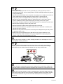
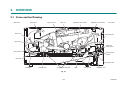
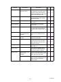
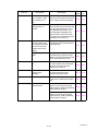
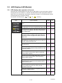
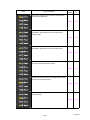
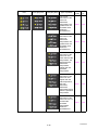
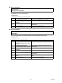
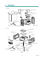
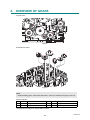
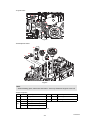
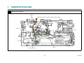
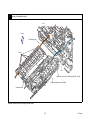
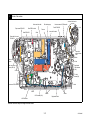
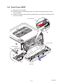
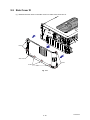
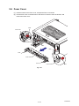
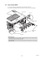
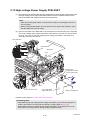
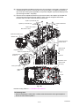
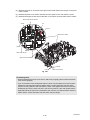
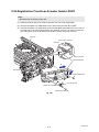
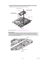
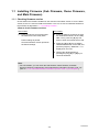
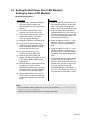
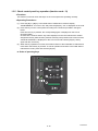
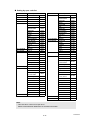
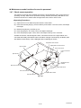
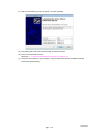
1
Brother Laser Printer SERVICE MANUAL MODEL: HL-L2305W/L2300D/L2320D/ L2340DW/L2360DN/L2360DW/ L2365DW/2260/2260D/2560DN/ L2321D/L2361DN/L2366DW Read this manual thoroughly before maintenance work. Keep this manual in a convenient place for quick and easy reference at all times. April 2014 SM-PRN096 84UF* (2) Confidential Trademarks Brother is a trademark of Brother Industries, Ltd. Microsoft, Windows, Windows NT, Windows Vista, Windows Server, Internet Explorer and Outlook are either registered trademarks or trademarks of Microsoft Corporation in the United States and/or other countries. Apple, Macintosh, Mac OS, iPad, iPhone, iOS, iPod touch and OS X are trademarks of Apple Inc., registered in the United States and other countries. Linux is the registered trademark of Linus Torvalds in the U.S. and other countries. UNIX is a registered trademark of The Open Group in the United States and other countries. Intel is a trademark of Intel Corporation in the U.S. and/or other countries. Adobe, Illustrator, PostScript and PostScript 3 are either registered trademarks or trademarks of Adobe Systems Incorporated in the United States and/or other countries. Wi-Fi, Wi-Fi Alliance and Wi-Fi Protected Access are registered trademarks of the Wi-Fi Alliance. WPA, WPA2, Wi-Fi Protected Setup, Wi-Fi Protected Setup logo and Wi-Fi Direct are trademarks of the Wi-Fi Alliance. FLICKR is a registered trademark of Yahoo! Inc. AOSS is a trademark of Buffalo Inc. Android, Google Cloud Print, Google Drive, Google Play and Picasa Web Albums are trademarks of Google Inc. Use of this trademark is subject to Google Permissions. Nuance, the Nuance logo, PaperPort and ScanSoft are trademarks or registered trademarks of Nuance Communications, Inc. or its affiliates in the United States and/or other countries. Firefox is a registered trademark of the Mozilla Foundation. EVERNOTE and the Evernote Elephant logo are trademarks of Evernote Corporation and used under a license. Each company whose software title is mentioned in this manual has a Software License Agreement specific to its proprietary programs. Any trade names and product names of companies appearing on Brother products, related documents and any other materials are all trademarks or registered trademarks of those respective companies. Confidential Open Source Licensing Remarks This product includes open-source software. Please visit the Brother Solutions Center at http://solutions.brother.com/ to view the Open Source Licensing Remarks and Copyright information. Copyright and License ©2014 Brother Industries, Ltd. All rights reserved. This product includes software developed by the following vendors: ©1983-1998 PACIFIC SOFTWORKS, INC. ALL RIGHTS RESERVED. ©2008 Devicescape Software, Inc. All rights reserved. This product includes the “KASAGO TCP/IP” software developed by ZUKEN ELMIC, Inc. Other Information FlashFX® is a registered trademark of Datalight, Inc. FlashFX® Copyright 1998-2010 Datalight, Inc. U.S.Patent Office 5,860,082/6,260,156 FlashFX® Pro™ is a trademark of Datalight, Inc. Reliance™ is a trademark of Datalight, Inc. Datalight® is a registered trademark of Datalight, Inc. Copyright 1989-2010 Datalight, Inc., All Rights Reserved Confidential CONTENTS REGULATION ...........................................................................................................vi SAFETY INFORMATION ...........................................................................................xi CHAPTER 1 SUPPLEMENTAL SPECIFICATIONS 1. GENERAL ................................................................................................................................... 1-1 2. NETWORK CONNECTIVITY ....................................................................................................... 1-3 3. SERVICE INFORMATION ........................................................................................................... 1-3 4. SUPPLIES ................................................................................................................................... 1-4 CHAPTER 2 ERROR INDICATIONS & TROUBLESHOOTING 1. INTRODUCTION ......................................................................................................................... 2-1 1.1 Precautions ......................................................................................................................... 2-1 1.2 Checks before Commencing Troubleshooting .................................................................... 2-2 2. OVERVIEW ................................................................................................................................. 2-4 2.1 Cross-section Drawing ........................................................................................................ 2-4 2.2 Paper Feeding .................................................................................................................... 2-5 2.3 Operation of Each Part ....................................................................................................... 2-6 2.4 Block Diagram .................................................................................................................... 2-7 2.5 Main Components ............................................................................................................... 2-8 3. ERROR INDICATIONS ................................................................................................................ 2-9 3.1 Error Codes ........................................................................................................................ 2-9 3.2 Error Messages ................................................................................................................ 2-16 3.3 LED Display (LED Models) ............................................................................................... 2-19 3.3.1 LED display when operator call occurs ................................................................ 2-19 3.3.2 LED display when service call occurs .................................................................. 2-22 4. TROUBLESHOOTING .............................................................................................................. 2-26 4.1 Error Cause and Remedy ................................................................................................. 2-26 4.2 Troubleshooting for Paper Feeding Problems .................................................................. 2-47 4.2.1 No paper is fed from paper tray ............................................................................ 2-47 4.2.2 No paper is fed from manual feed slot ................................................................. 2-48 4.2.3 Multiple sheets of paper are fed ........................................................................... 2-48 4.2.4 Paper becomes wrinkled ...................................................................................... 2-49 4.2.5 Paper is fed at an angle ....................................................................................... 2-50 4.2.6 Paper is curled ..................................................................................................... 2-51 4.2.7 Duplex printing is not possible .............................................................................. 2-51 4.2.8 Paper jam ............................................................................................................. 2-52 i Confidential 4.3 4.4 Troubleshooting for Image Defects ................................................................................... 2-56 4.3.1 Image defect examples ....................................................................................... 2-56 4.3.2 Troubleshooting according to image defect ......................................................... 2-57 Troubleshooting for Software Problems ........................................................................... 2-68 4.4.1 4.5 4.6 4.7 4.8 Troubleshooting for Network Problems ............................................................................ 2-69 4.5.1 Cannot print via network connection .................................................................... 2-69 4.5.2 Cannot connect to access point ........................................................................... 2-69 Troubleshooting for Control Panel Problems .................................................................... 2-70 4.6.1 Nothing is displayed on the LCD .......................................................................... 2-70 4.6.2 Nothing is displayed on the LED .......................................................................... 2-70 4.6.3 Control panel is inoperable ................................................................................... 2-70 Troubleshooting for Toner and Drum Problems ............................................................... 2-71 4.7.1 New toner is not detected ..................................................................................... 2-71 4.7.2 Toner cartridge cannot be recognized .................................................................. 2-71 4.7.3 Error message prompting toner cartridge replacement does not disappear ........ 2-72 4.7.4 Drum error ............................................................................................................ 2-72 4.7.5 Error message prompting drum replacement does not disappear ....................... 2-72 Troubleshooting for Fuser Unit Problems ......................................................................... 2-73 4.8.1 4.9 Cannot receive data ............................................................................................. 2-68 Fuser unit failure ................................................................................................... 2-73 Troubleshooting for Laser Unit Problems ......................................................................... 2-73 4.9.1 Laser unit failure ................................................................................................... 2-73 4.10 Troubleshooting for PCB Problems .................................................................................. 2-74 4.10.1 Main PCB failure .................................................................................................. 2-74 4.10.2 Memory full ........................................................................................................... 2-74 4.10.3 Print limit / ID authentification error ...................................................................... 2-74 4.11 Troubleshooting for Other Problems ................................................................................. 2-75 4.11.1 Cannot print ......................................................................................................... 2-75 4.11.2 Cannot update firmware ...................................................................................... 2-75 CHAPTER 3 DISASSEMBLY/REASSEMBLY 1. SAFETY PRECAUTIONS ............................................................................................................ 3-1 2. PACKING .................................................................................................................................... 3-2 3. SCREW CATALOGUE ................................................................................................................ 3-3 4. SCREW TORQUE LIST .............................................................................................................. 3-4 5. LUBRICATION ............................................................................................................................ 3-5 6. OVERVIEW OF GEARS .............................................................................................................. 3-6 7. HARNESS ROUTING .................................................................................................................. 3-8 8. DISASSEMBLY FLOW CHART ................................................................................................ 3-13 ii Confidential 9. DISASSEMBLY PROCEDURE ................................................................................................. 3-14 9.1 Preparation ....................................................................................................................... 3-14 9.2 Back Cover ....................................................................................................................... 3-15 9.3 Outer Chute ASSY ............................................................................................................ 3-16 9.4 Front Cover ASSY ............................................................................................................ 3-17 9.5 Side Cover R .................................................................................................................... 3-18 9.6 Fuser Cover ...................................................................................................................... 3-19 9.7 Inner Chute ASSY ............................................................................................................ 3-20 9.8 Side Cover L ..................................................................................................................... 3-21 9.9 Top Cover ASSY .............................................................................................................. 3-22 9.10 Fuser Unit ......................................................................................................................... 3-25 9.11 Low-voltage Power Supply PCB ASSY ............................................................................ 3-27 9.12 Fan ................................................................................................................................... 3-29 9.13 High-voltage Power Supply PCB ASSY ........................................................................... 3-30 9.14 Filter .................................................................................................................................. 3-32 9.15 Laser Unit ......................................................................................................................... 3-33 9.16 Wireless LAN PCB (Wireless network model only) .......................................................... 3-35 9.17 Roller Holder ASSY .......................................................................................................... 3-36 9.18 Main PCB ASSY ............................................................................................................... 3-37 9.19 T1 Clutch and Registration Clutch .................................................................................... 3-38 9.20 New Toner Sensor PCB ASSY ......................................................................................... 3-39 9.21 Main Frame L ASSY ......................................................................................................... 3-40 9.22 Main Motor ........................................................................................................................ 3-42 9.23 Fuser Gear 67R/40R ........................................................................................................ 3-44 9.24 Eject Sensor PCB ASSY .................................................................................................. 3-45 9.25 Registration Front/rear Actuator Holder ASSY ................................................................. 3-47 CHAPTER 4 ADJUSTING AND UPDATING SETTINGS AS REQUIRED AFTER PARTS REPLACEMENT 1. IF YOU REPLACE THE MAIN PCB ASSY ................................................................................. 4-1 1.1 Installing Firmware (Sub Firmware, Demo Firmware, and Main Firmware) ....................... 4-2 1.1.1 Checking firmware version ..................................................................................... 4-2 1.1.2 Installing firmware .................................................................................................. 4-3 1.2 Setting Default Paper Size (LED Models) / Setting by Spec (LCD Models) ....................... 4-4 1.3 Setting Serial Number and Entering Adjusted Value of Laser Unit ..................................... 4-5 2. IF YOU REPLACE THE LOW-VOLTAGE POWER SUPPLY PCB ASSY ................................. 4-6 2.1 Reset Irregular Power Supply Detection Counter of Low-voltage Power Supply PCB .......... 4-6 3. IF YOU REPLACE THE LASER UNIT ........................................................................................ 4-7 3.1 Entering Adjusted Value of Laser Unit ................................................................................ 4-8 iii Confidential CHAPTER 5 SERVICE FUNCTIONS 1. MAINTENANCE MODE ............................................................................................................... 5-1 1.1 1.2 1.3 How to Enter Maintenance Mode ....................................................................................... 5-1 1.1.1 Method of entering maintenance mode for service personnel ............................... 5-1 1.1.2 Method of entering end-user accessible maintenance mode ................................. 5-2 List of Maintenance Mode Functions .................................................................................. 5-3 1.2.1 List of maintenance mode functions for LCD models ............................................. 5-3 1.2.2 List of maintenance mode functions using [Go] key (LED models) ........................ 5-4 Details of Maintenance Mode Functions for LCD Models ................................................... 5-6 1.3.1 Initialize EEPROM parameters (function code: 01, 91) .......................................... 5-6 1.3.2 Print quality test pattern (function code: 09) ........................................................... 5-7 1.3.3 Set worker switches (WSW) and print worker switch setting data (function code: 10, 11) ............................................................................................ 5-8 1.3.4 Check LCD operation (function code: 12) ............................................................ 5-11 1.3.5 Check control panel key operation (function code: 13) ........................................ 5-12 1.3.6 Display software version (function code: 25) ........................................................ 5-13 1.3.7 Change OnePushDemo function setting (function code: 28) ............................... 5-14 1.3.8 Check sensor operation (function code: 32) ......................................................... 5-15 1.3.9 Display LAN connection status (function code: 33) .............................................. 5-16 1.3.10 Change USB No. return value / Adjust left-end print start position on second side when duplex printing (function code: 45) ......................................... 5-17 1.3.11 Continuous print test (function code: 67) .............................................................. 5-18 1.3.12 Print frame pattern (single-side printing) (function code: 69) ............................... 5-22 1.3.13 Print frame pattern (duplex printing) (function code: 70) ...................................... 5-23 1.3.14 Print test pattern (function code: 71) .................................................................... 5-24 1.3.15 Setting by spec (function code: 74) ...................................................................... 5-26 1.3.16 Print maintenance information (function code: 77) ............................................... 5-28 1.3.17 Check fan operation (function code: 78) .............................................................. 5-30 1.3.18 Display machine log information (function code: 80) ............................................ 5-31 1.3.19 Display machine error code (function code: 82) ................................................... 5-33 1.3.20 Reset irregular power supply detection counter of low-voltage power supply PCB (function code: 88) .............................................. 5-33 1.3.21 Quit maintenance mode (function code: 99) ........................................................ 5-33 1.4 Details of Maintenance Mode Functions Using [Go] key (LED models) ........................... 5-34 1.4.1 Test printing .......................................................................................................... 5-34 1.4.2 Change USB No. return value .............................................................................. 5-35 1.4.3 Factory Reset / Settings Reset ............................................................................. 5-35 1.4.4 Quiet mode ........................................................................................................... 5-36 1.4.5 Engine error ignore mode ..................................................................................... 5-36 1.4.6 One Push printing recovery mode ........................................................................ 5-36 1.4.7 Check sensor operation ....................................................................................... 5-37 1.4.8 Print continuous lattice pattern ............................................................................. 5-38 1.4.9 Check RAM .......................................................................................................... 5-38 1.4.10 Change ON/OFF setting for duplex printing ......................................................... 5-39 1.4.11 Change A4/Letter setting for paper size ............................................................... 5-39 1.4.12 Maintenance printing ............................................................................................ 5-40 iv Confidential 1.4.13 Print maintenance data and frame pattern ........................................................... 5-40 1.4.14 Change Ready LED light intensity in sleep mode ................................................ 5-41 1.4.15 Reset irregular power supply detection counter of low-voltage power supply PCB ............................................................................. 5-41 1.4.16 Firmware installing mode ..................................................................................... 5-42 1.4.17 Ready state of maintenance mode for service personnel .................................... 5-42 2. OTHER SERVICE FUNCTIONS ................................................................................................ 5-43 2.1 Engine Error Ignore Mode (LCD models only) .................................................................. 5-43 2.2 Change USB No. Return Value / Adjust Left-end Print Start Position on Second Side when Duplex Printing (LCD models only) .................................................... 5-44 2.3 Print Printer Settings ......................................................................................................... 5-45 CHAPTER 6 WIRING DIAGRAM 1. WIRING DIAGRAM ..................................................................................................................... 6-1 CHAPTER 7 PERIODICAL MAINTENANCE 1. PERIODICAL REPLACEMENT PARTS ..................................................................................... 7-1 APPENDIX 1 SERIAL NUMBERING SYSTEM APPENDIX 2 DELETING USER SETTING INFORMATION APPENDIX 3 INSTALLING THE MAINTENANCE PRINTER DRIVER v Confidential REGULATION Declaration of Conformity (Europe only) We, Brother Industries, Ltd. 15-1, Naeshiro-cho, Mizuho-ku, Nagoya 467-8561 Japan declare that this product is in conformity with the essential requirements of all relevant directives and regulations applied within the European Community. The Declaration of Conformity (DoC) can be downloaded from our website. Visit http://support.brother.com and: select Europe select country select your model select “Manuals”. Your Declaration will be downloaded as a PDF file. IEC60825-1:2007 Specification (For 220-240V models only) This product is a Class 1 laser product as defined in IEC60825-1:2007 specifications. The label shown below is attached in countries where required. This product has a Class 3B Laser Diode which emits invisible laser radiation in the Laser Unit. The Laser Unit should not be opened under any circumstances. CLASS 1 LASER PRODUCT APPAREIL À LASER DE CLASSE 1 LASER KLASSE 1 PRODUKT Internal Laser radiation Wave Length: 770 - 800 nm Output: 25 mW max. Laser Class: Class 3B WARNING Use of controls, adjustments or performance of procedures other than those specified in this manual may result in hazardous radiation exposure. Wireless LAN (Models with Wireless LAN function only) This product supports Wireless LAN. vi Confidential Disconnect Device CAUTION This product must be installed near an electrical socket that is easily accessible. In case of emergencies, you must disconnect the power cord from the electrical socket to shut off power completely. Wiring Information (U.K. only) If you need to replace the plug fuse, fit a fuse that is approved by ASTA to BS1362 with the same rating as the original fuse. Always replace the fuse cover. Never use a plug that does not have a cover. If in any doubt, call a qualified electrician. Warning -This product must be earthed. The wires in the mains lead are coloured in line with the following code: • Green and Yellow: Earth • Blue: Neutral • Brown: Live LAN Connection (Network models only) CAUTION DO NOT connect this product to a LAN connection that is subject to over-voltages. Radio Interference This product complies with EN55022 (CISPR Publication 22)/Class B. Recycling Information in accordance with the WEEE and Battery Directives Product mark Battery mark European Union only The product/battery is marked with one of the above recycling symbols. It indicates that at the end of the life of the product/battery, you should dispose of it separately at an appropriate collection point and not place it in the normal domestic waste stream. vii Confidential International ENERGY STAR® Qualification Statement The purpose of the International ENERGY STAR® Program is to promote the development and popularization of energy-efficient office equipment. As an ENERGY STAR® Partner, Brother Industries, Ltd. has determined that this product meets the ENERGY STAR® specifications for energy efficiency. Federal Communications Commission (FCC) Declaration of Conformity (USA only) Responsible Party: Brother International Corporation 200 Crossing Boulevard Bridgewater, NJ 08807-0911 USA TEL: (908) 704-1700 declares, that the products Product Name: Mono Laser Printer Model Numbers: HL-L2300D / HL-L2320D / HL-L2340DW / HL-L2360DW comply with Part 15 of the FCC Rules. Operation is subject to the following two conditions: (1) This device may not cause harmful interference, and (2) this device must accept any interference received, including interference that may cause undesired operation. This equipment has been tested and found to comply with the limits for a Class B digital device, pursuant to Part 15 of the FCC Rules. These limits are designed to provide reasonable protection against harmful interference in a residential installation. This equipment generates, uses, and can radiate radio frequency energy and, if not installed and used in accordance with the instructions, may cause harmful interference to radio communications. However, there is no guarantee that interference will not occur in a particular installation. If this equipment does cause harmful interference to radio or television reception, which can be determined by turning the equipment off and on, the user is encouraged to try to correct the interference by one or more of the following measures: • Reorient or relocate the receiving antenna. • Increase the separation between the equipment and receiver. • Connect the equipment into an outlet on a circuit different from that to which the receiver is connected. • Call the dealer or an experienced radio/TV technician for help. • (Wireless network models only) This transmitter must not be co-located or operated in conjunction with any other antenna or transmitter. viii Confidential IMPORTANT • Changes or modifications not expressly approved by Brother Industries, Ltd. could void the user’s authority to operate the equipment. • A shielded interface cable should be used to ensure compliance with the limits for a Class B digital device. RF Exposure Notice (USA or Canada only) (Wireless models only) This equipment complies with FCC/IC radiation exposure limits set forth for an uncontrolled environment and meets the FCC radio frequency (RF) Exposure Guidelines in Supplement C to OET65 and RSS-102 of the IC radio frequency (RF) Exposure rules. This equipment should be installed and operated keeping the radiator at least 20 cm or more away from person’s body (excluding extremities: hands, wrists, feet and ankles). Cet équipement est conforme aux limites d’exposition aux rayonnements énoncées pour un environnement non contrôlé et respecte les règles les radioélectriques (RF) de la FCC lignes directrices d'exposition dans le Supplément C à OET65 et d’exposition aux frequencies radioélectriques (RF) CNR-102 de l’IC. Cet équipement doit être installé et utilisé en gardant une distance de 20 cm ou plus entre le dispositif rayonnant et le corps (à l’exception des extrémités : mains, poignets, pieds et chevilles). Wireless Connection (Mexico only) The operation of this equipment is subject to the following two conditions: (1) it is possible that this equipment or device may not cause harmful interference, and (2) this equipment or device must accept any interference, including interference that may cause undesired operation. La operación de este equipo está sujeta a las siguientes dos condiciones: (1) es posible que este equipo o dispositivo no cause interferencia perjudicial y (2) este equipo o dispositivo debe aceptar cualquier interferencia, incluyendo la que pueda causar su operación no deseada. Industry Canada Compliance Statement (Canada only) This device complies with Industry Canada licence-exempt RSS standard(s). Operation is subject to the following two conditions: (1) this device may not cause interference, and (2) this device must accept any interference, including interference that may cause undesired operation of the device. Le présent appareil est conforme aux CNR d’Industrie Canada applicables aux appareils radio exempts de licence. L'exploitation est autorisée aux deux conditions suivantes: (1) l'appareil ne doit pas produire de brouillage, et (2) l'utilisateur de l'appareil doit accepter tout brouillage radioélectrique subi, même si le brouillage est susceptible d'en compromettre le fonctionnement. ix Confidential Laser Safety (For 110-120V models only) This equipment is certified as a Class 1 laser product as defined in IEC60825-1:2007 specifications under the U.S. Department of Health and Human Services (DHHS) Radiation Performance Standard according to the Radiation Control for Health and Safety Act of 1968. This means that the equipment does not produce hazardous laser radiation. Since radiation emitted inside the equipment is completely confined within protective housings and external covers, the laser beam cannot escape from the product during any phase of user operation. FDA Regulations (For 110-120V models only) U.S. Food and Drug Administration (FDA) has implemented regulations for laser products manufactured on and after August 2, 1976. Compliance is mandatory for products marketed in the United States. One of the following labels on the back of the product indicates compliance with the FDA regulations and must be attached to laser products marketed in the United States. Manufactured: BROTHER INDUSTRIES (VIETNAM) LTD. Phuc Dien Industrial Zone Cam Phuc Commune, Cam giang Dist Hai Duong Province, Vietnam This product complies with FDA performance standards for laser products except for deviations pursuant to Laser Notice No. 50, dated June 24, 2007. WARNING Use of controls, adjustments or performance of procedures other than those specified in this manual may result in hazardous invisible radiation exposure. Internal laser radiation Max. Radiation Power: 25 mW Wave Length: 770 - 800 nm Laser Class: Class 3B For use in the USA or Canada only These products are made for use in the USA and Canada only. We cannot recommend using them overseas because it may violate the power requirements of your product may not be compatible with the power available in foreign countries. Using USA or Canada models overseas is at your own risk and may void your warranty. x Confidential SAFETY INFORMATION Definitions of Warnings, Cautions, Notes and Memos The following conventions are used in this manual: WARNING WARNING indicates a potentially hazardous situation which, if not avoided, could result in death or serious injuries. CAUTION CAUTION indicates a potentially hazardous situation which, if not avoided, may result in minor or moderate injuries. IMPORTANT IMPORTANT indicates a potentially hazardous situation which, if not avoided, may result in damage to property or loss of product functionality. Prohibition icons indicate actions that must not be performed. Electrical Hazard icons alert you to possible electrical Shock. Fire hazard icons alert you to the possibility of fire. Hot Surface icons warn you not to touch product parts that are hot. Note Notes tell you how you should respond to a situation that may arise or give tips about how the operation works with other features. Memo Memo tells you bits of knowledge to help understand the machine. xi Confidential To use the Machine Safely Please keep these instructions for later reference and read them before attempting any maintenance. If you do not follow these safety instructions, there is a possibility of a fire, electrical shock, burn or suffocation. WARNING ELECTRICAL HAZARDS Failure to follow the warnings in this section may create the risk of an electrical shock. In addition, you could create an electrical short, which may create the risk of a fire. There are high voltage electrodes inside the product. Before you access the inside of the product, including for routine maintenance such as cleaning, make sure you have unplugged the power cord from the AC power outlet, as well as Ethernet (RJ-45) cables (Network models only) from the product. Never push objects of any kind into this product through cabinet slots, since they may touch dangerous voltage points or short out parts. DO NOT handle the plug with wet hands. DO NOT use this product during an electrical storm. Always make sure the plug is fully inserted. DO NOT use the product or handle the cord if the cord has become worn or frayed. DO NOT allow this product to come into contact with water. This product should be connected to an AC power source within the range indicated on the rating label. DO NOT connect it to a DC power source or inverter. xii Confidential Power Cord Safety: • This product is equipped with a 3-wire grounded plug. This plug will only fit into a grounded power outlet. This is a safety feature. DO NOT attempt to defeat the purpose of the grounded plug. • DO NOT pull on the middle of the AC power cord; pulling on the middle may cause the cord to separate from the plug. Doing this might cause an electrical shock. • Only use the power cord supplied with this product (for certain models only). • DO NOT use any undesignated cables (or optional devices). It may cause a fire or injuries. Installation must be performed properly according to the user's guide. • This product should be positioned so that nothing pinches or constricts the power cord. • DO NOT allow anything to rest on the power cord. • DO NOT place this product where people may step on the cord. • DO NOT place this product in a position where the cord is stretched or strained, as it may become worn or frayed. • DO NOT use the product if the power cord is frayed or damaged. Doing so may cause an electrical shock or fire. • Brother strongly recommends that you DO NOT use any type of extension cord. • DO NOT drop any metallic hardware or any type of liquid on the power plug of the product. It may cause an electrical shock or a fire. DO NOT put a toner cartridge or a toner cartridge and drum unit assembly into a fire. It could explode, resulting in injuries. DO NOT use flammable substances, any type of spray, or an organic solvent/liquid containing alcohol or ammonia to clean the inside or outside of the product. Doing so could cause a fire or electrical shock. Instead, use only a dry, lint-free cloth. DO NOT attempt to operate this product when a paper jam or stray pieces of paper are inside the product. Prolonged contact of the paper with the fuser unit could cause a fire. DO NOT use a vacuum cleaner to clean up scattered toner. Doing this might cause the toner dust to ignite inside the vacuum cleaner, potentially starting a fire. Please carefully clean the toner dust with a dry, lint-free soft cloth and dispose of it according to local regulations. xiii Confidential HOT SURFACE After you have just used the product, some internal parts of the product will be extremely hot. Wait at least ten minutes for the product to cool down before you touch the internal parts of the product. Caution for Laser Product (WARNHINWEIS fur Laser drucker) CAUTION: When the machine during servicing is operated with the cover open, the regulations of VBG 93 and the performance instructions for VBG 93 are valid. CAUTION: In case of any trouble with the laser unit, replace the laser unit itself. To prevent direct exposure to the laser beam, do not try to open the enclosure of the laser unit. ACHTUNG: Im Falle von Störungen der Lasereinheit muß diese ersetzt werden. Das Gehäuse der Lasereinheit darf nicht geöffnet werden, da sonst Laserstrahlen austreten können. Additional Information When servicing the optical system of the machine, be careful not to place a screwdriver or other reflective object in the path of the laser beam. Be sure to take off any personal accessories such as watches and rings before working on the machine. A reflected beam, though invisible, can permanently damage the eyes. Since the beam is invisible, the following caution in print is attached on the laser unit. In print xiv Confidential CHAPTER 1 SUPPLEMENTAL SPECIFICATIONS 1. GENERAL The function comparative table for models as described in this Service Manual are shown below. HL-L2320D HL-L2360DN HL-L2360DW HL-2260D HL-L2340DW HL-2560DN HL-L2365DW HL-L2321D HL-L2361DN HL-L2366DW HL-L2305W HL-L2300D HL-2260 Wired/ Wireless LAN Wired/ Wireless N/A N/A N/A Wireless Wired Wired/ Wireless Duplex printing N/A N/A N/A N/A N/A Model LCD Model HL-L2305W HL-L2300D HL-2260 Warm-up time From Sleep mode Less than 9 seconds at 73.4F (23°C) From Power OFF ON Less than 26 seconds at 73.4F (23°C) First print time From Ready mode Less than 8.5 seconds at 73.4F (23°C) From Sleep mode Less than 17.5 seconds at 73.4F (23°C) CPU Dimensions (W x D x H) Weights ARM9 266 MHz Carton size 441 x 286 x 504 mm (17.4 x 11.3 x 19.8 inch) Machine size 356 x 360 x 183 mm (14.0 x 14.2 x 7.2 inch) with Carton 7.7 kg / 17.0 lb 7.9 kg / 17.4 lb (for the U.S.A.) 8.0 kg / 17.7 lb (for Europe) 7.8 kg / 17.3 lb without Carton with toner/drum 6.6 kg / 14.6 lb 6.8 kg / 15.0 lb (for the U.S.A.) 6.9 kg / 15.2 lb (for Europe) 6.5 kg / 14.3 lb without Carton nor 5.7 kg / 12.6 lb toner/drum 524 x 451 x 291 mm (20.6 x 17.8 x 11.5 inch) 5.9 kg / 13.0 lb 5.6 kg / 12.3 lb (Except for Europe) 5.7 kg / 12.6 lb (for Europe) Specifications are subject to change without notice. 1-1 Confidential Model HL-L2320D HL-2260D HL-L2321D HL-L2360DN HL-L2360DW HL-L2340DW HL-2560DN HL-L2365DW HL-L2361DN HL-L2366DW Warm-up time From Sleep mode Less than 9 seconds at 73.4F (23°C) From Power OFF ON Less than 26 seconds at 73.4F (23°C) First print time From Ready mode Less than 8.5 seconds at 73.4F (23°C) From Sleep mode Less than 17.5 seconds at 73.4F (23°C) CPU Dimensions (W x D x H) Weights ARM9 266 MHz Carton size 441 x 286 x 504 mm (17.4 x 11.3 x 19.8 inch) (Except for China) 524 x 451 x 291 mm (20.6 x 17.8 x 11.5 inch) (for China) Machine size 356 x 360 x 183 mm (14.0 x 14.2 x 7.2 inch) with Carton 7.9 kg / 17.4 lb (Except for China / Europe) 8.0 kg / 17.7 lb (for China / Europe) without Carton with toner/drum 6.8 kg / 15.0 lb (Except for China / Europe) 6.7 kg / 14.8 lb (for China) 6.9 kg / 15.2 lb (for Europe) without Carton nor 5.9 kg / 13.0 lb toner/drum (Except for China) 5.8 kg / 12.8 lb (for China) 5.9 kg / 13.0 lb (Except for Europe) 5.7kg / 12.6lb (for Europe) 5.9 kg / 13.0 lb (Except for China / Europe) 5.7 kg / 12.6 lb (for Europe) 5.8 kg / 12.8 lb (for China) 5.9 kg / 13.0 lb (Except for China / Europe) 5.7 kg / 12.6 lb (for Europe) Specifications are subject to change without notice. 1-2 Confidential 2. NETWORK CONNECTIVITY Model Wired network Network node type Wireless network Network node type Model Wired network HL-L2305W HL-L2300D HL-2260 N/A NC-8300w N/A HL-L2320D HL-L2360DN HL-L2360DW HL-2260D HL-L2340DW HL-2560DN HL-L2365DW HL-L2321D HL-L2361DN HL-L2366DW Network node type N/A Wireless network Network node type N/A NC-8700h NC-8300w N/A NC-8300w Specifications are subject to change without notice. 3. SERVICE INFORMATION Model All models Machine life 50,000 pages (A4 / LTR) or 5 years MTBF 4,000 hours MTTR 0.5 hours Maximum monthly volume Up to 10,000 pages Parts life Fuser Unit 50,000 pages Laser Unit 50,000 pages PF kit 50,000 pages Specifications are subject to change without notice. 1-3 Confidential 4. SUPPLIES Model Toner cartridge HL-L2305W HL-L2300D Starter Toner *1 Approximately 700 pages Standard Toner Approximately 1,200 pages High Capacity Toner Approximately 2,600 pages HL-2260 HL-L2320D Approximately Approximately 2,600 pages 700 pages (Except for Asia/China) Approximately 2,600 pages (for Asia/ China) When printing A4/Letter size one-sided pages in accordance with ISO/IEC 19752 Shelf life: 2 years without opening (6 months after opening) Drum unit Life expectancy: Approximately 12,000 pages (1 page/job) The life expectancy varies according to the use condition. Shelf life: 2 years The shelf life of toner cartridge and drum unit is guaranteed under the normal condition as below; (Temperature) Normal condition: 0 to 40°C * Storage condition at the temperature of 40 to 50°C: Up to 5 days * Storage condition at the temperature of -20 to 0°C: Up to 5 days (Humidity) Normal condition: 35 to 85% (without condensation) * Storage condition at the humidity of 85 to 95%: Up to 5 days (without condensation) * Storage condition at the humidity of 10 to 35%: Up to 5 days (without condensation) *1 Toner supplied with the machine. Specifications are subject to change without notice. 1-4 Confidential Model Toner cartridge HL-2260D HL-L2321D HL-L2360DW HL-L2340DW HL-2560DN HL-L2365DW HL-L2360DN HL-L2361DN HL-L2366DW Starter Toner *1 Approximately 700 pages (Except for Asia/China) Approximately 2,600 pages (for Asia/China) Approximately 700 pages (for the U.S.A./ Oceania) Approximately 1,200 pages (for Europe) Approximately 2,600 pages (for Asia) Standard Toner Approximately Approximately Approximately 1,200 pages 1,200 pages 1,200 pages (for China) (for China) N/A (Except N/A (Except for China) for China) Approximately 1,200 pages (Except for Asia) N/A (for Asia) High Capacity Toner Approximately 2,600 pages When printing A4/Letter size one-sided pages in accordance with ISO/IEC 19752 Shelf life: 2 years without opening (6 months after opening) Drum unit Life expectancy: Approximately 12,000 pages (1 page/job) The life expectancy varies according to the use condition. Shelf life: 2 years The shelf life of toner cartridge and drum unit is guaranteed under the normal condition as below; (Temperature) Normal condition: 0 to 40°C * Storage condition at the temperature of 40 to 50°C: Up to 5 days * Storage condition at the temperature of -20 to 0°C: Up to 5 days (Humidity) Normal condition: 35 to 85% (without condensation) * Storage condition at the humidity of 85 to 95%: Up to 5 days (without condensation) * Storage condition at the humidity of 10 to 35%: Up to 5 days (without condensation) *1 Toner supplied with the machine. Specifications are subject to change without notice. 1-5 Confidential CHAPTER 2 ERROR INDICATIONS & TROUBLESHOOTING 1. INTRODUCTION Troubleshooting is a collection of solution procedures that service personnel should follow if an error or malfunction occurs in the machine. It is difficult to determine troubleshooting procedures for all possible problems that may occur in the future. Therefore, this chapter describes typical problems and recovery procedures for these. These will help service personnel identify and repair other similar defective sections. 1.1 Precautions Be sure to observe the following precautions to prevent any secondary problems occurring during troubleshooting: (1) Be sure to unplug the AC cord before removing any covers or PCBs, adjusting the machine, or conducting continuity tests using a tester. (2) Do not hold the cable when connecting or disconnecting the cable. Be sure to hold the connector. (3) Static electricity charged in your body may damage electronic parts. Before handling the PCBs, touch a metal section of the machine to discharge static electricity. When transporting PCBs, be sure to wrap them in conductive sheets. When replacing the PCBs, wear a grounding wrist band and perform replacement on an antistatic mat. Also take care not to touch the conductor sections on the flat cables. (4) Be sure to always observe all warnings. Warning Hazard labels as shown below are attached to the machine. Fully understand the descriptions on the hazard labels and observe them during troubleshooting. Take extreme care not to remove or damage the hazard labels. Warning DO NOT use any flammable spray or flammable solvent such as alcohol, benzine, or thinner in or around the machine. Otherwise a fire or electric shock may result. (5) After repair is completed, check that the repaired sections, including those removed once and then remounted, operate normally. 2-1 Confidential 1.2 Checks before Commencing Troubleshooting Check the following items before commencing repairs on the machine. Operating environment (1) The machine is placed on a flat, stable surface. (2) The machine is used in a clean environment where the temperature is 10°C (50°F) to 32.5°C (90.5°F), and the relative humidity is maintained between 20% and 80%. (3) The machine is not exposed to direct sunlight, excessive heat, moisture, or dust. (4) Hold the machine level while moving it. Be sure to move or lift the machine with two or more people. Power supply (1) Power described on the rating label attached on the machine is supplied. Power fluctuation should be within ±10% of the rated voltage. (2) The AC input power supply is within the regulated value. (3) The cables and harnesses are connected correctly. (4) The fuses are not blown. Paper (1) The recommended type of paper is being used. (2) The document is not damp. (3) Short-grained paper or acid paper is not used. Consumable parts (1) The drum unit (including toner cartridge) is set correctly. 2-2 Confidential Others (1) Condensation When the machine is moved to a warm room from a cold location, condensation may occur inside the machine, causing various problems as listed below. • Condensation on the surface of optical devices such as the lens, reflecting mirror and protection glass may cause light print image. • If the exposure drum is cold, the electrical resistance of the photosensitive layer is increased, making it impossible to obtain the correct print density. • Condensation on the charge unit may cause corona charge leakage. • Condensation on the plate or separation pad may cause paper feed problems. If condensation has formed in the machine, leave the machine for at least two hours until it reaches room temperature. If the drum unit is unpacked soon after it is moved to a warm room from a cold location, condensation may occur inside the unit which may cause printing failure. Leave the drum unit for one or two hours until it reaches room temperature, and then unpack it. (2) Low temperature The motor may not operate normally in a cold environment because too much load is applied to each drive. In this case, increase the room temperature. Cleaning Use a soft lint-free cloth. Warning DO NOT use any flammable spray or flammable solvent such as alcohol, benzine, or thinner to clean the machine. DO NOT use these articles near the machine. 2-3 Confidential 2. OVERVIEW 2.1 Cross-section Drawing <Back side> Eject roller 2 Exposure drum Laser unit Registration rear actuator Registration front actuator Back cover <Front side> Manual feed slot Eject roller 1 Paper dust cleaning roller Eject actuator Paper detection actuator Heat roller Separation pad Duplex tray Pressure roller Duplex paper feed roller Plate Pick-up roller Separation roller Fig. 2-1 2-4 Confidential 2.2 Paper Feeding Eject to output tray Feed from manual feed slot Eject to back side <Front side> <Back side> Duplex path Fig. 2-2 2-5 Confidential 2.3 Operation of Each Part Part name Operation Pick-up roller Feeds paper from the paper tray to the separation roller. Separation roller Separation pad Separates paper fed from the paper tray into single sheets. Paper feed actuator (Paper feed sensor) Detects the paper tray (open / closed). Detects paper in the paper tray. Detects paper jams in the front section of the machine. Registration front actuator (Registration front sensor) Detects the front edge of the paper to control the registration roller drive. Detects paper jams in the front section of the machine. Determines whether paper is fed from the paper tray. Registration roller Corrects the paper alignment when the paper makes contact with the stopped registration roller. After the correction, it rotates to feed the paper to the feeding path. Registration rear actuator (Registration rear sensor) Detects paper pass and adjusts the writing start position for the paper. Detects paper jams in the front or center section of the machine. Detects the rear edge of the paper to determine the paper size. Heat roller Pressure roller Fuses the toner transferred to paper by heat and pressure, and feeds paper to the eject roller 1. Eject actuator (Eject sensor) Determines whether paper is ejected from the fuser unit. Detects the rear edge of the paper in duplex printing mode to adjust the turn-over timing of the eject roller 2. Eject roller 1 Feeds the paper ejected from the fuser unit to eject roller 2. Eject roller 2 Ejects paper to the face-down output tray. During the duplex printing, the eject roller 2 rotates conversely and feeds paper to the duplex tray after the paper has been fed from the eject roller 2 with the first side printed. Duplex paper feed roller Feeds paper pass through the duplex tray to the registration roller. Front cover sensor Detects open front cover. Back cover/duplex tray empty Detects open / closed back cover or the duplex tray is set. sensor 2-6 Confidential 2.4 Block Diagram LCD models LCD Panel PCB * WLAN model only WLAN LED Wireless LAN PCB * WLAN model only Power key Registration front/rear sensor PCB LED models Registration front sensor LED panel PCB High-voltage power supply PCB Toner LED Drum LED Front cover sensor Paper LED Registration rear sensor Fan Ready LED Power key Main PCB T1 clutch New toner sensor PCB New toner sensor Registration clutch Paper feed sensor PCB ASSY Paper feed sensor Main motor Back cover/duplex tray empty sensor Eject sensor PCB Center thermistor Eject sensor LD PCB BD sensor Laser unit Side thermistor Fuser unit Heater Polygon motor Low-voltage power supply PCB Heater relay Fig. 2-3 2-7 Confidential 2.5 Main Components Top cover ASSY (LCD models) Top cover ASSY (LED models) Back cover Filter Air duct Laser unit Outer chute ASSY Fuser cover Inner chute ASSY Side cover R LVPS shield plate cover Fan Fuser unit Duplex tray LVPS insulation sheet High-voltage power supply PCB ASSY Low-voltage power supply PCB ASSY Eject sensor PCB ASSY Fuser gear 67R/40R Roller holder ASSY Main PCB ASSY Wireless LAN PCB Registration clutch New toner sensor PCB ASSY Front cover ASSY Registration front/rear actuator holder ASSY T1 clutch Motor drive sub ASSY Paper tray Side cover L Fig. 2-4 2-8 Confidential 3. ERROR INDICATIONS This machine includes a self-diagnosis function. If the machine does not work normally it judges that an error has occurred, and indicates the corresponding error message on the LCD, which in turn helps the service personnel to quickly find out the problem. 3.1 Error Codes Errors in shaded column do not usually occur during normal use. The possible causes are noise around the installation site, fluctuation of the power supply voltage, and failures in the software. Error codes Description Refer to: Error codes Description Refer to: 0504 After the heat unit was heated normally, the center thermistor of the fuser unit detected a temperature lower than the specified value. 2-28 0505 The center thermistor of the fuser unit detected a temperature rise greater than the specified value within the specified time. 2-28 0100 ― 0201 Cannot detect the synchronized signal of the main motor. The speed of the main motor does not stabilize within the specified time. 0202 ― 0506 The center thermistor of the fuser unit detected a temperature fall greater than the specified value within the specified time. 2-29 0203 ― 050A The hardware detected a temperature error through the center thermistor or the side thermistor of the fuser unit. 2-30 0204 ― 050B When the center thermistor of the fuser unit was lower than the idle temperature, the side thermistor detected a temperature higher than the specified temperature. 2-30 0205 ― 050C When the center thermistor of the fuser unit was higher than the idle temperature, the side thermistor detected a temperature lower than the specified temperature. 2-30 0206 ― 050D ― 0207 ― 050F An error occurred in the fuser unit. 2-30 0208 ― 0600 A communication error occurred between the ASIC controlled by engine and the motor driver. 2-31 0209 ― 0700 ― 0300 Cannot detect the lock signal of the polygon motor for the laser unit (second time). 2-27 0800 ― 0305 Cannot detect the lock signal of the polygon motor for the laser unit (first time). 2-27 0900 Detected irregular power supply for more than 100 times. 0401 Cannot detect the synchronized signal of the polygon motor for the laser unit (second time). 2-27 0A01 ― 0402 ― 0405 Cannot detect the synchronized signal of the polygon motor for the laser unit (first time). 0501 2-26 2-31 0A02 Detected a fan failure. 2-32 2-27 0B01 An error occurred in the high-voltage power supply PCB ASSY while operating. 2-32 The center thermistor of the fuser unit has not reached the specified temperature within the specified time. 2-28 0B02 An error occurred in the high-voltage power supply PCB ASSY when the machine was in the ready state. 2-32 0502 The center thermistor of the fuser unit has not reached the specified temperature within the specified time after it was heated normally to the certain level. 2-28 0C00 ― 0503 The center thermistor of the fuser unit detected a temperature higher than the specified value. 2-28 0D01 ― 2-9 Confidential Error codes Description Refer to: Error codes Description 0D02 ― 2402 ― 0D03 ― 2403 ― 0D04 ― 2404 ― 0E00 ― 2405 ― 1003 ― 2408 ― 1004 ― 2409 ― 1100 ― 2501 ― 1200 ― 2502 ― 1300 ― 2503 ― 1400 ― 2504 ― 1500 ― 2601 ― 1C00 ― 2602 ― 1D01 ― 2603 ― 1D02 ― 2604 ― 1D03 ― 2605 ― 1D04 ― 2701 ― 1E01 ― 2702 ― 1E02 ― 2703 ― 2001 ― 2801 ― 2002 ― 2802 ― 2003 ― 2803 ― 2004 ― 2804 ― 2005 ― 2805 ― 2006 ― 2806 ― 2101 ― 2901 ― 2102 ― 2902 ― 2103 ― 2903 ― 2104 ― 2904 ― 2105 ― 2905 ― 2201 ― 2906 ― 2202 ― 2A01 ― 2203 ― 2A02 ― 2204 ― 2A03 ― 2205 ― 2B01 ― 2206 ― 2B02 ― 2207 ― 2C01 ― 2301 ― 2C02 ― 2302 ― 2D01 ― 2401 ― 2E01 ― 2-10 Refer to: Confidential Error codes Description Refer to: Error codes Refer to: Description 2E02 ― 3A00 ― 2E03 ― 4000 The number of rotations of the drum unit is reaching the upper limit. 2E04 ― 4001 ― 2E05 ― 4002 ― 2E06 ― 4003 ― 2E07 ― 4004 ― 2E08 ― 4200 The number of rotations of the drum unit has reached the upper limit. (Printing does not stop.) 2E0A ― 4201 ― 2F01 ― 4202 ― 2F02 ― 4203 ― 2F03 ― 4204 ― 2F04 ― 4208 ― 2F05 ― 4300 ― 2F06 ― 4400 ― 2F07 ― 4408 ― 2F08 ― 4500 ― 2F0A ― 4600 ― 3001 ― 4700 ― 3002 ― 4800 ― 3003 ― 4900 ― 3102 ― 4A00 ― 3202 ― 4B01 Dot count or develop roller counter of the toner is reaching the upper limit. 3301 ― 4B02 ― 3302 ― 4B03 ― 3401 ― 4B04 ― 3402 ― 4C01 Dot count or develop roller counter of the toner has reached the upper limit in the toner stop mode. 3501 ― 4C02 ― 3601 ― 4C03 ― 3701 ― 4C04 ― 3702 ― 4C05 ― 3703 ― 4D01 Dot count or develop roller counter of the toner has reached the upper limit in the toner continuous printing mode. 2-34 3801 ― 4E01 The toner cartridge has reached the upper limit in the toner continuous printing mode. 2-34 3802 ― 4F01 The new toner sensor could not detect the new toner cartridge correctly. 2-34 3900 ― 4F02 ― 2-11 2-33 2-33 2-33 2-34 Confidential Error codes Description Refer to: Error codes Refer to: Description 4F03 ― 6200 ― 4F04 ― 6201 ― 5001 ― 6202 ― 5002 ― 6203 ― 5003 ― 6204 ― 5004 ― 6208 ― 5005 ― 6209 ― 5100 ― 620A ― 5200 ― 6300 ― 5301 ― 6400 ― 5302 ― 6602 ― 5401 ― 6701 ― 5402 ― 6801 The side thermistor of the fuser unit detected a temperature higher than the specified value. 5406 ― 6802 ― 5502 ― 6901 An error occurred in the fuser unit when the power switch was turned ON or sleep mode was released. 2-37 2-37 2-38 2-36 5602 ― 6902 Rechecking the error after the power switch was turned OFF and then ON again because an error was detected in the fuser unit. (This message is displayed for approximately 15 minutes when the machine is restarted after error code 6901 has occurred.) 5702 ― 6A00 Detected discharge that may be attributable to dirty corona wire on the drum unit. 5801 ― 6B01 ― 5802 ― 6B02 ― 5902 ― 6B03 ― 5A02 ― 6B04 ― 5B02 ― 6B0A ― 5C02 ― 6C01 ― 6001 The front cover sensor detected that the front cover was open. 6C02 ― 6002 ― 6C03 ― 6003 ― 6C04 ― 6004 The eject sensor detected that the fuser cover was open. 6D00 ― 6007 ― 6E00 ― 6101 The new toner sensor detected that the toner cartridge was not set. 6F00 Detected irregular power supply for less than 100 times. 2-39 6102 ― 7000 The eject sensor does not detect paper pass after the registration rear sensor detected the paper pass. 2-39 6103 ― 7001 ― 6104 ― 7002 ― 2-35 2-35 2-36 2-12 Confidential Error codes Description Refer to: Error codes Refer to: Description 7003 ― 7D00 ― 7004 ― 7E00 ― 7100 The eject sensor remains ON (paper pass detected) even after the registration rear sensor detected the end of paper pass. 8000 First side printing started before receiving the second side data in duplex printing mode due to the insufficient memory. 7101 ― 8401 ― 7102 ― 8402 ― 7103 ― 8501 ― 7104 ― 8502 ― 7105 ― 8503 ― 7106 ― 8504 ― 7200 ― 8505 ― 7300 When printing from the paper tray, the registration front sensor does not detect paper pass within the specified time after the paper feed sensor detected paper pass. 8506 ― 7301 ― 8507 ― 7400 ― 8508 ― 7401 ― 8601 ― 7501 ― 8602 ― 7502 ― 8603 ― 7601 ― 8604 ― 7602 ― 8701 ― 7700 The registration front sensor does not detect paper pass within the specified time after the first side was printed in duplex printing mode. 8702 ― 7701 ― 8703 ― 7702 ― 8801 ― 7703 ― 8802 ― 7704 ― 8901 ― 7705 ― 8902 ― 2-42 2-40 2-40 2-41 2-42 7801 ― 8903 The back cover sensor detected that the cover was open in duplex printing mode. (Before registering printing data to engine) 7802 ― 8904 The back cover sensor detected that the cover was open in duplex printing mode. (After registering printing data to engine) 2-42 7900 ― 8A01 The registration rear sensor detected that the paper fed was smaller or larger than the specified size in duplex printing mode. 2-43 7C00 The eject sensor was ON when the power switch was turned ON. 8A02 ― 2-41 2-13 Confidential Error codes Description Refer to: Error codes 2-43 9601 ― Description 8C00 There is no paper set in the manual feed slot on the manual feed slot fix mode. 8D01 ― 9608 ― 8D02 ― 9701 A tray set to duplex printingincompatible size was specified in duplex printing. 8E01 ― 9702 ― 8E02 ― 9703 ― 8E03 ― 9704 ― 8F01 ― 9705 ― 8F02 ― 9801 ― 8F03 ― 9802 ― 9001 ― 9803 ― 9002 When printing from the paper tray, the size of paper set in the paper tray does not match the size specified by the driver. 9804 ― 9003 ― 9901 ― 9004 ― 9902 ― 9005 ― 9903 ― 9102 ― 9A01 ― 9103 ― 9A02 ― 9104 ― 9A03 ― 9105 ― 9C01 ― 9200 ― 9C02 ― 9301 ― 9C03 ― 9302 When printing from the paper tray, the paper feed sensor detected that there was no paper set in the paper tray. 9C06 ― 9303 ― 9C07 ― 9304 ― A000 ― 9305 ― A200 ― 9306 ― A300 ― 9307 ― A400 ― 9401 ― A500 ― 9402 ― A600 ― 9403 ― A700 ― 9404 ― A800 ― 9501 ― A900 ― 9502 ― AA00 ― 9503 ― AB00 ― 9504 ― AC00 ― 9505 ― AD00 ― 2-44 2-44 2-14 Refer to: 2-44 Confidential Error codes Description Refer to: Error codes Description Refer to: AF00 ― E500 An error occurred during access to the DRAM in the main PCB ASSY. 2-45 B000 ― E600 Write error in the EEPROM of the main PCB ASSY 2-45 B300 ― E701 ― B400 ― E702 Read error in the flash ROM on the main PCB B700 ― E900 ― B800 ― EC00 ― B900 ― F900 The country code was not entered correctly. BA00 ― FA01 ― BB00 ― FA02 ― BC00 ― FA03 ― BD00 ― FB01 ― BE00 ― FB02 ― BF00 ― FB03 ― C001 ― FB04 ― C002 ― FB05 ― C003 ― FB06 ― C004 ― FB07 ― C700 There is insufficient memory to expand PC print data. FB08 ― C800 ― FB09 ― C900 ― FB0A ― CA00 ― FB0B ― D100 ― FB0C ― D200 ― FB0D ― D800 ― FB0F ― D900 ― FC01 ― DA00 ― FC02 ― DB00 ― FC03 ― 2-45 E000 An error occurred in the ROM check sum. 2-45 FC04 ― E100 Program error 2-45 FC05 ― E400 ― 2-15 2-45 2-46 Confidential 3.2 Error Messages First line Cartridge Error Second line Description Put the Toner Cartridge back in. The new toner sensor could not detect the new toner cartridge correctly. 4F01 2-34 Multiple access points were found as a result of the access point search. --- 4.5.2 Connection failed although the access point was found as a result of the access point search. --- 4.5.2 The side thermistor of the fuser unit detected a temperature higher than the specified value. 6801 2-36 Close the Front Cover. The front cover sensor detected that the front cover was open. 6001 2-35 Close the Fuser Cover The eject sensor detected that the fuser cover was open. which can be found behind the Back Cover of the machine. 6004 2-35 Make sure there is no The eject sensor was ON when paper jammed inside the power switch was turned ON. the machine and close the Back Cover, then press Go. 7C00 2-41 Slide the Green tab on Detected discharge that may be Drum Unit. attributable to dirty corona wire on the drum unit. 6A00 2-38 The number of rotations of the drum unit is reaching the upper limit. 4000 2-33 Pull out the Duplex Tray at the back of the machine and remove the jammed paper. The registration front sensor does not detect paper pass within the specified time after the first side was printed in duplex printing mode. 7700 2-41 Open the Front Cover, pull out the Drum Unit completely and remove the jammed paper. The eject sensor does not detect paper pass after the registration rear sensor detected the paper pass. 7000 2-39 Open the Back Cover and remove the jammed paper, then press Go. The eject sensor remains ON (paper pass detected) even after the registration rear sensor detected the end of paper pass. 7100 2-40 Connection Error ― Connection Fail Cooling Down Cover is Open Drum ! Drum End Soon Jam 2-sided Jam Inside Jam Rear Error Refer codes to: ― Wait for a while ― 2-16 Confidential First line Jam Tray 1 Manual Feed Second line Remove the jammed paper from Tray 1. Load paper. Description Error Refer codes to: When printing from the paper tray, the registration front sensor does not detect paper pass within the specified time after the paper feed sensor detected paper pass. 7300 2-40 There is no paper set in the manual feed slot on the manual feed slot fix mode. 8C00 2-43 Machine Error ** ― A machine error occurred. Refer to error code “**”. --- No Access Point ― Cannot find the connectable access point. --- 4.5.2 No Paper Load paper. When printing from the paper tray, the paper feed sensor detected that there was no paper set in the tray. 9302 2-44 Open the Front Cover, The new toner sensor detected then install the Toner that the toner cartridge was not set. Cartridge. 6101 2-36 Out of Memory Press Go for 2 seconds. There is insufficient memory to expand PC print data. C700 2-45 Print Overrun ― First side printing started before receiving the second side data in duplex printing mode due to the insufficient memory. 8000 2-42 --- --- 4200 2-33 4C01 2-34 4D01 2-34 No Toner Print Unable ** Replace Drum Replace Toner Printing related error. Refer to error code “**”. ― The number of rotations of the drum unit has reached the upper limit. (Printing does not stop.) Open the Front Cover, Dot count or develop roller counter replace Toner of the toner has reached the upper Cartridge. limit in the toner stop mode. ― Dot count or develop roller counter of the toner has reached the upper limit in the toner continuous printing mode. 2-17 Confidential First line Self-Diagnostic Size Error DX Size Mismatch Toner Ended Toner Low 2-sided Disabled Second line Description Turn the power off, then on again. Leave the machine for 15 min. An error occurred in the fuser unit when the power switch was turned ON or sleep mode was released. Will Automatically Restart within 15 minutes. Error Refer codes to: 6901 2-37 Rechecking the error after the power switch was turned OFF and then ON again because an error was detected in the fuser unit. (This message is displayed for approximately 15 minutes when the machine is restarted after error code 6901 has occurred.) 6902 2-37 Press Go for 2 A tray set to duplex printingseconds. Specify the incompatible size was specified in correct paper and load duplex printing. the same size paper as the Printer driver setting. 9701 2-44 Specify the correct paper. The registration rear sensor detected that the paper fed was smaller or larger than the specified size in duplex printing mode. 8A01 2-43 Load paper and press Go. When printing from the paper tray, the size of paper set in the paper tray does not match the size specified by the driver. 9002 2-44 4E01 2-34 Dot count or develop roller counter of the toner is reaching the upper limit. 4B01 2-33 The back cover sensor detected that the cover was open during duplex printing. (Before registering printing data to engine) 8903 2-42 The back cover sensor detected that the cover was open during duplex printing. (After registering printing data to engine) 8904 2-42 Open the Front Cover, The toner cartridge has reached replace Toner the upper limit in the toner Cartridge. continuous printing mode. ― Close the Back Cover of the machine. 2-18 Confidential 3.3 LED Display (LED Models) 3.3.1 LED display when operator call occurs Determine the message details according to the LED display on the control panel. Refer to the page shown in the "Refer to:" column in the table below to take appropriate measures. Most errors are automatically cleared after measures are taken. If not automatically cleared, press the [Go] key to reset the machine. LED status in the table below: LED : Unlit : Lit : Flashing Error codes Refer to: The eject sensor detected that the fuser cover was open. 6004 2-35 The eject sensor does not detect paper pass after the registration rear sensor detected the paper pass. 7000 2-39 The eject sensor remains ON (paper pass detected) even after the registration rear sensor detected the end of paper pass. 7100 2-40 When printing from the paper tray, the registration front sensor does not detect paper pass within the specified time after the paper feed sensor detected paper pass. 7300 2-40 The registration front sensor does not detect paper pass within the specified time after the first side was printed in duplex printing mode. 7700 2-41 The eject sensor was ON when the power switch was turned ON. 7C00 2-41 First side printing started before receiving the second side data in duplex printing mode due to the insufficient memory. 8000 2-42 The back cover sensor detected that the cover was open in duplex printing mode. (Before registering printing data to engine) 8903 2-42 The back cover sensor detected that the cover was open in duplex printing mode. (After registering printing data to engine) 8904 2-42 The registration rear sensor detected that the paper fed was smaller or larger than the specified size in duplex printing mode. 8A01 2-43 When printing from the paper tray, the size of paper set in the paper tray does not match the size specified by the driver. 9002 2-44 A tray set to duplex printing-incompatible size was specified in duplex printing. 9701 2-44 There is insufficient memory to expand PC print data. C700 2-45 Type of problem 2-19 Confidential LED Type of problem Error codes Refer to: 4B01 2-33 4D01 2-34 4C01 2-34 4E01 2-34 6A00 2-38 4000 2-33 Dot count or develop roller counter of the toner is reaching the upper limit. Dot count or develop roller counter of the toner has reached the upper limit in the toner continuous printing mode. Dot count or develop roller counter of the toner has reached the upper limit in the toner stop mode. The toner cartridge has reached the upper limit in the toner continuous printing mode. Detected discharge that may be attributable to dirty corona wire on the drum unit. The number of rotations of the drum unit is reaching the upper limit. 2-20 Confidential Error codes Refer to: 4200 2-33 8C00 2-43 9302 2-44 4F01 2-34 6101 2-36 An error occurred in the ROM check sum. E000 2-45 Program error E100 2-45 An error occurred during access to the DRAM in the main PCB ASSY. E500 2-45 E702 2-45 6801 2-36 LED Type of problem The number of rotations of the drum unit has reached the upper limit. There is no paper set in the manual feed slot on the manual feed slot fix mode. When printing from the paper tray, the paper feed sensor detected that there was no paper set in the paper tray. The new toner sensor could not detect the new toner cartridge correctly. The new toner sensor detected that the toner cartridge was not set. Read error in the flash ROM on the main PCB The side thermistor of the fuser unit detected a temperature higher than the specified value. 2-21 Confidential 3.3.2 LED display when service call occurs When a service call occurs, the four LEDs flash. Pressing the [Go] key allows you to identify the location of the problem based on the combination of the LED status: lit, flashing or unlit. Pressing the [Go] key again allows you to see detailed information. Follow the table below to identity the location of the problem and take appropriate measures. LED Press [Go] once Press [Go] twice Type of problem Error codes Refer to: Cannot detect the synchronized signal of the main motor. The speed of the main motor does not stabilize within the specified time. 0201 2-26 An error occurred in the highvoltage power supply PCB ASSY when the machine was in the ready state. 0B02 2-32 0600 2-31 0B01 2-32 0300 2-27 0401 2-27 A communication error occurred between the ASIC controlled by engine and the motor driver. An error occurred in the highvoltage power supply PCB ASSY while operating. Cannot detect the lock signal of the polygon motor for the laser unit (second time). Cannot detect the synchronized signal of the polygon motor for the laser unit (second time). 2-22 Confidential LED Press [Go] once Press [Go] twice Error codes Refer to: E600 2-45 0A02 2-32 Detected irregular power supply for more than 100 times. 0900 2-31 Detected irregular power supply for less than 100 times. 6F00 2-39 The center thermistor of the fuser unit has not reached the specified temperature within the specified time after it was heated normally to the certain level. 0502 2-28 The hardware detected a temperature error through the center thermistor or the side thermistor of the fuser unit. 050A 2-30 An error occurred in the fuser unit. 050F 2-30 Type of problem Write error in the EEPROM of the main PCB ASSY Detected a fan failure. 2-23 Confidential LED Press [Go] once Press [Go] twice 2-24 Type of problem Error codes Refer to: An error occurred in the fuser unit when the power switch was turned ON or sleep mode was released. 6901 2-37 Rechecking the error after the power switch was turned OFF and then ON again because an error was detected in the fuser unit. (This message is displayed for approximately 15 minutes when the machine is restarted after error code 6901 has occurred.) 6902 2-37 The center thermistor of the fuser unit detected a temperature higher than the specified value. 0503 2-28 After the heat unit was heated normally, the center thermistor of the fuser unit detected a temperature lower than the specified value. 0504 2-28 Confidential LED Press [Go] once Press [Go] twice 2-25 Error codes Refer to: The center thermistor of the fuser unit detected a temperature rise greater than the specified value within the specified time. 0505 2-28 The center thermistor of the fuser unit detected a temperature fall greater than the specified value within the specified time. 0506 2-29 When the center thermistor of the fuser unit was lower than the idle temperature, the side thermistor detected a temperature higher than the specified temperature. 050B 2-30 When the center thermistor of the fuser unit was higher than the idle temperature, the side thermistor detected a temperature lower than the specified temperature. 050C 2-30 The center thermistor of the fuser unit has not reached the specified temperature within the specified time. 0501 2-28 Type of problem Confidential 4. TROUBLESHOOTING 4.1 Error Cause and Remedy Error code 0201 Print Unable 02 Turn the power off and then back on again. Cannot detect the synchronized signal of the main motor. The speed of the main motor does not stabilize within the specified time. Step Cause Remedy 3 Connection failure of the main motor flat cable Connection failure of the LVPS harness Damaged fuser gear Replace the fuser gear. 4 Main motor failure Replace the main motor. 5 Damaged fuser unit Replace the fuser unit. Low-voltage power supply PCB failure Damaged part in motor drive sub ASSY Main PCB failure Replace the low-voltage power supply PCB ASSY. Replace the main frame L ASSY. 1 2 6 7 8 Reconnect the main motor flat cable. Reconnect the LVPS harness. Replace the main PCB ASSY. 2-26 Confidential Error code 0300 Print Unable 03 Turn the power off and then back on again. Cannot detect the lock signal of the polygon motor for the laser unit (second time). Error code 0305 Print Unable 03 Turn the power off and then back on again. Cannot detect the lock signal of the polygon motor for the laser unit (first time). Error code 0401 Print Unable 04 Turn the power off and then back on again. Cannot detect the synchronized signal of the polygon motor for the laser unit (second time). Error code 0405 Print Unable 04 Turn the power off and then back on again. Cannot detect the synchronized signal of the polygon motor for the laser unit (first time). Step Cause Remedy 2 Connection failure of the laser unit flat cable Laser unit flat cable failure Replace the laser unit flat cable. 3 Laser unit failure Replace the laser unit. 4 Main PCB failure Replace the main PCB ASSY. 1 Reconnect the laser unit flat cable. 2-27 Confidential Error code 0501 Print Unable 05 Turn the power off and then back on again. The center thermistor of the fuser unit has not reached the specified temperature within the specified time. Error code 0502 Print Unable 05 Turn the power off and then back on again. The center thermistor of the fuser unit has not reached the specified temperature within the specified time after it was heated normally to the certain level. Error code 0503 Print Unable 05 Turn the power off and then back on again. The center thermistor of the fuser unit detected a temperature higher than the specified value. Error code 0504 Print Unable 05 Turn the power off and then back on again. After the heat unit was heated normally, the center thermistor of the fuser unit detected a temperature lower than the specified value. Error code 0505 Print Unable 05 Turn the power off and then back on again. The center thermistor of the fuser unit detected a temperature rise greater than the specified value within the specified time. 2-28 Confidential Error code 0506 Print Unable 05 Turn the power off and then back on again. The center thermistor of the fuser unit detected a temperature fall greater than the specified value within the specified time. <User Check> • Turn OFF the power switch. After several seconds, turn ON the power again and check that this error is reset. Step Cause Remedy 5 Connection failure of the center or side thermistor harness of the fuser unit Connection failure of the fuser unit heater harness Connection failure of the eject sensor PCB flat cable Connection failure of the LVPS harness Eject sensor PCB failure Replace the eject sensor PCB ASSY. 6 Fuser unit failure Replace the fuser unit. 1 2 3 4 7 8 Reconnect the center or side thermistor harness of the fuser unit. Reconnect the fuser unit heater harness. Reconnect the eject sensor PCB flat cable. Reconnect the LVPS harness. Low-voltage power supply PCB Replace the low-voltage power supply PCB failure ASSY. Main PCB failure Replace the main PCB ASSY. 2-29 Confidential Error code 050A Print Unable 05 Turn the power off and then back on again. The hardware detected a temperature error through the center thermistor or the side thermistor of the fuser unit. Error code 050B Print Unable 05 Turn the power off and then back on again. When the center thermistor of the fuser unit was lower than the idle temperature, the side thermistor detected a temperature higher than the specified temperature. Error code 050C Print Unable 05 Turn the power off and then back on again. When the center thermistor of the fuser unit was higher than the idle temperature, the side thermistor detected a temperature lower than the specified temperature. Error code 050F Print Unable 05 Turn the power off and then back on again. An error occurred in the fuser unit. <User Check> • Turn OFF the power switch. After several seconds, turn ON the power again and check that this error is reset. Step Cause Remedy 5 Connection failure of the center or side thermistor harness of the fuser unit Connection failure of the fuser unit heater harness Connection failure of the eject sensor PCB flat cable Connection failure of the LVPS harness Eject sensor PCB failure Replace the eject sensor PCB ASSY. 6 Fuser unit failure Replace the fuser unit. 1 2 3 4 7 8 Reconnect the center or side thermistor harness of the fuser unit. Reconnect the fuser unit heater harness. Reconnect the eject sensor PCB flat cable. Reconnect the LVPS harness. Low-voltage power supply PCB Replace the low-voltage power supply PCB failure ASSY. Main PCB failure Replace the main PCB ASSY. 2-30 Confidential Error code 0600 Print Unable 06 Turn the power off and then back on again. A communication error occurred between the ASIC controlled by engine and the motor driver. Step 1 Cause Main PCB failure Remedy Replace the main PCB ASSY. Error code 0900 Print Unable 09 Turn the power off and then back on again. Detected irregular power supply for more than 100 times. <User Check> • Turn OFF the power switch. After several seconds, turn ON the power again and check that this error is reset. Step 1 2 Cause Remedy Low-voltage power supply PCB Replace the low-voltage power supply PCB failure ASSY. Refer to “1.3.20 Reset irregular power supply detection counter of low-voltage power supply PCB (function code: 88)” in Chapter 5 to reset the irregular power supply detection counter. Main PCB failure Replace the main PCB ASSY. Note: • The irregular power supply detection error of the low-voltage power supply PCB (error code: 0900) occurs when there is a large distortion in the power supply voltage supplied to the machine. In this case, if the same power supply is used, the same error may occur even when the low-voltage power supply PCB ASSY is replaced. Ask the user to review the installation environment. 2-31 Confidential Error code 0A02 Print Unable 0A Turn the power off and then back on again. Detected a fan failure. Step 1 2 3 4 5 6 Cause Remedy Connection failure of the fan Reconnect the fan harness. harness Connection failure of the HVPS Reconnect the HVPS flat cable. flat cable Fan failure Replace the fan. Low-voltage power supply PCB failure High-voltage power supply PCB failure Main PCB failure Replace the low-voltage power supply PCB ASSY. Replace the high-voltage power supply PCB ASSY. Replace the main PCB ASSY. Error code 0B01 Print Unable 0B Turn the power off and then back on again. An error occurred in the high-voltage power supply PCB ASSY while operating. Error code 0B02 Print Unable 0B Turn the power off and then back on again. An error occurred in the high-voltage power supply PCB ASSY when the machine was in the ready state. Step 1 2 3 Cause Remedy Connection failure of the HVPS flat cable High-voltage power supply PCB failure Main PCB failure Reconnect the HVPS flat cable. Replace the high-voltage power supply PCB ASSY. Replace the main PCB ASSY. 2-32 Confidential Error code 4000 Drum End Soon The number of rotations of the drum unit is reaching the upper limit. Error code 4200 Replace Drum The number of rotations of the drum unit has reached the upper limit. (Printing does not stop.) <User Check> • Prepare a new drum unit. Step 1 Cause Remedy Replace the drum unit with a Replace the main PCB ASSY. new one and reset the drum counter. If the error display is not cleared, the main PCB is faulty. Error code 4B01 Toner Low Dot count or develop roller counter of the toner is reaching the upper limit. <User Check> • Prepare a new toner cartridge. Step 1 Cause Main PCB failure Remedy Replace the main PCB ASSY. 2-33 Confidential Error code 4C01 Replace Toner Open the Front Cover, replace Toner Cartridge. Dot count or develop roller counter of the toner has reached the upper limit in the toner stop mode. Error code 4D01 Replace Toner Dot count or develop roller counter of the toner has reached the upper limit in the toner continuous printing mode. Error code 4E01 Toner Ended Open the Front Cover, replace Toner Cartridge. The toner cartridge has reached the upper limit in the toner continuous printing mode. <User Check> • Replace the toner cartridge which has reached the upper limit. Step 1 Cause Remedy If the error display is not cleared Replace the main PCB ASSY. after replacing the toner cartridge with a new one, the main PCB is faulty. Error code 4F01 Cartridge Error Put the Toner Cartridge back in. The new toner sensor could not detect the new toner cartridge correctly. <User Check> • Replace the toner cartridge with a new one again. • If the machine is on the uneven surface, place it on a level surface. Step Cause Remedy 4 Connection failure of the new toner sensor PCB flat cable New toner actuator coming off or caught in sections of the machine Develop joint coming off or caught in sections of the machine New toner sensor failure Replace the new toner sensor PCB ASSY. 5 Panel PCB failure Replace the panel PCB ASSY. 6 If the error display is not cleared Replace the main PCB ASSY. after replacing the toner cartridge with a new one, the main PCB is faulty. 1 2 3 Reconnect the new toner sensor PCB flat cable. Reattach the new toner actuator. Reattach the develop joint. 2-34 Confidential Error code 6001 Cover is Open Close the Front Cover. The front cover sensor detected that the front cover was open. <User Check> • Close the front cover. Step 1 2 3 Cause Remedy Front cover failure Replace the front cover. Front cover sensor failure Replace the high-voltage power supply PCB ASSY. Replace the main PCB ASSY. Main PCB failure Error code 6004 Cover is Open Close the Fuser Cover which can be found behind the Back Cover of the machine. The eject sensor detected the open fuser cover was open. <User Check> • Close the fuser cover. Step 1 2 Cause Eject actuator coming off or caught in sections of the machine Fuser cover attachment failure Remedy Reattach the eject actuator. Reattach the fuser cover. 4 Connection failure of the eject sensor PCB flat cable Eject sensor PCB failure Replace the eject sensor PCB ASSY. 5 Main PCB failure Replace the main PCB ASSY. 3 Reconnect the eject sensor PCB flat cable. 2-35 Confidential Error code 6101 No Toner Open the Front Cover, then install Toner Cartridge. The new toner sensor detected that the toner cartridge was not set. <User Check> • Set the toner cartridge correctly. • Replace the toner cartridge with a new one. Step Cause Remedy New toner actuator coming off Reattach the new toner actuator. Reconnect the new toner sensor PCB flat cable. Reconnect the panel PCB flat cable. 4 Connection failure of the new toner sensor PCB flat cable Connection failure of the panel PCB flat cable New toner sensor PCB failure Replace the new toner sensor PCB ASSY. 5 Panel PCB failure Replace the panel PCB ASSY. 6 Main PCB failure Replace the main PCB ASSY. 1 2 3 Error code 6801 Cooling Down Wait for a while The side thermistor of the fuser unit detected a temperature higher than the specified value. <User Check> • Lower the room temperature. • Keep the machine away from heating appliances. Step Cause Remedy 1 Side thermistor failure Replace the fuser unit. 2 Main PCB failure Replace the main PCB ASSY. 2-36 Confidential Error code 6901 Self-Diagnostic Turn the power off, then on again. Leave the machine for 15 min. An error occurred in the fuser unit when the power switch was turned ON or sleep mode was released. Error code 6902 Self-Diagnostic Will Automatically Restart within 15 minutes. Rechecking the error after the power switch was turned OFF and then ON again because an error was detected in the fuser unit. (This message is displayed for approximately 15 minutes when the machine is restarted after error code 6901 has occurred.) Step Cause Remedy 3 Connection failure of each fuser Reconnect each harness of the fuser unit. unit harness Connection failure of the eject Reconnect the eject sensor PCB flat cable. sensor PCB flat cable Fuser unit failure Replace the fuser unit. 4 Eject sensor PCB failure 1 2 5 6 Replace the eject sensor PCB ASSY. Low-voltage power supply PCB Replace the low-voltage power supply PCB failure ASSY. Main PCB failure Replace the main PCB ASSY. Note: • Turn OFF the power switch. After the fuser unit has cooled sufficiently, turn ON the power switch again and leave the machine for 15 minutes. This problem may then be cleared. • To release the fuser unit error after taking appropriate measures, enter the maintenance mode once and quit it with the maintenance code 99. 2-37 Confidential Error code 6A00 Drum ! Slide the Green tab on Drum Unit. Detected discharge that may be attributable to dirty corona wire on the drum unit. <User Check> • Slide the green tab of the drum unit to left and right for two to three times to clean the corona wire. • Clean the terminal of the drum unit. • Replace the drum unit. Step 1 2 3 4 Cause Remedy Dirt on the high-voltage power supply PCB terminal High voltage electrodes attachment failure High-voltage power supply PCB failure Main PCB failure Clean the electrodes of the machine. Check if the problem disappears after pressing each electrode. If not, reattach the electrodes. Replace the high-voltage power supply PCB ASSY. Replace the main PCB ASSY. Electrodes location of the toner cartridge and drum unit Side surface of drum unit Bottom surface of drum unit Fig. 2-5 Electrodes location of the machine Fig. 2-6 2-38 Confidential Error code 6F00 Print Unable ZC Turn the power off and then back on again. Detected irregular power supply for less than 100 times. <User Check> • Turn the power switch OFF and then back ON again. • Put a filter into the power supply. • Install a voltage stabilizer to the power supply unit. Error code 7000 Jam Inside Open the Front Cover, pull out the Drum Unit completely and remove the jammed paper. The eject sensor does not detect paper pass after the registration rear sensor detected the paper pass. <User Check> • Remove the jammed paper. Step Cause Remedy 4 Foreign object inside the machine Connection failure of the eject sensor PCB flat cable Eject actuator coming off or caught in sections of the machine Fuser cover attachment failure Reattach the fuser cover. 5 Eject sensor failure Replace the eject sensor PCB ASSY. 6 Fuser unit failure Replace the fuser unit. Damaged gears in the feeding system Main PCB failure Replace the main frame L ASSY. 1 2 3 7 8 Remove the foreign object. Reconnect the eject sensor PCB flat cable. Reattach the eject actuator. Replace the main PCB ASSY. 2-39 Confidential Error code 7100 Jam Rear Open the Back Cover and remove the jammed paper, then press Go. The eject sensor remains ON (paper pass detected) even after the registration rear sensor detected the end of paper pass. <User Check> • Remove the jammed paper. • Check if the back cover is open during duplex printing. Step Cause Remedy 3 Foreign object in the rear of the Remove the foreign object. machine Eject actuator caught in sections Reattach the eject actuator. of the machine Fuser cover attachment failure Reattach the fuser cover. 4 Eject sensor failure Replace the eject sensor PCB ASSY. 5 Fuser unit failure Replace the fuser unit. Damaged gears in the feeding system Main PCB failure Replace the main frame L ASSY. 1 2 6 7 Replace the main PCB ASSY. Error code 7300 Jam Tray 1 Remove the jammed paper from Tray 1. When printing from the paper tray, the registration front sensor does not detect paper pass within the specified time after the paper feed sensor detected paper pass. <User Check> • Remove the jammed paper. • Close the paper tray correctly. Step 1 2 3 4 5 6 7 8 9 10 Cause Remedy Foreign object in the front section of the paper tray Paper dust cleaning roller attachment failure Connection failure of the registration front/rear sensor PCB harness Connection failure of the HVPS flat cable Registration front actuator coming off or caught in some sections of the machine HVPS flat cable breakage Remove the foreign object. Reattach the paper dust cleaning roller. Reconnect the registration front/rear sensor PCB harness. Reconnect the HVPS flat cable. Reattach the registration front actuator. Replace the HVPS flat cable. Registration front sensor failure Replace the registration front/rear actuator holder ASSY. High-voltage power supply PCB Replace the high-voltage power supply PCB failure ASSY. Damaged gears in the feeding Replace the main frame L ASSY. system Main PCB failure Replace the main PCB ASSY. 2-40 Confidential Error code 7700 Jam 2-sided Pull out the Duplex Tray at the back of the machine and remove the jammed paper. The registration front sensor does not detect paper pass within the specified time after the first side was printed in duplex printing mode. <User Check> • Remove the jammed paper. • Close the back cover correctly. • Close the paper tray correctly. Step Cause Remedy 3 Foreign object in the duplex Remove the foreign object. paper feed system Foreign object in the duplex Remove the foreign object. paper feed system of the paper tray Back cover attachment failure Reattach the back cover. 4 Fuser cover attachment failure Reattach the fuser cover. 5 Duplex tray failure Replace the duplex tray. Damaged gears in the feeding system Main PCB failure Replace the main frame L ASSY. 1 2 6 7 Replace the main PCB ASSY. Error code 7C00 Cover is Open Make sure there is no paper jammed inside the machine and close the Back Cover, then press Go. The eject sensor was ON when the power switch was turned ON. <User Check> • Close the back cover correctly. Step Cause Remedy 1 Eject actuator caught in sections Reattach the eject actuator. of the machine 2 Fuser cover attachment failure Reattach the fuser cover. 3 Back cover attachment failure Reattach the back cover. 4 Eject sensor failure Replace the eject sensor PCB ASSY. 5 Main PCB failure Replace the main PCB ASSY. 2-41 Confidential Error code 8000 Print Overrun First side printing started before receiving the second side data in duplex printing mode due to the insufficient memory. <User Check> • Print the print data stored in the memory. • The size of printing data per page is too big. Change the printing contents to reduce the data size. • Switch to single-side printing. Step 1 Cause Remedy Main PCB failure Replace the main PCB ASSY. Error code 8903 2-sided Disabled Close the Back Cover of the machine. The back cover sensor detected that the cover was open in duplex printing mode. (Before registering printing data to engine) Error code 8904 2-sided Disabled Close the Back Cover of the machine. The back cover sensor detected that the cover was open in duplex printing mode. (After registering printing data to engine) <User Check> • Close the back cover correctly. Step 1 2 3 4 Cause Back cover/duplex tray empty sensor attachment failure Boss to push the back cover sensor is broken. Back cover/duplex tray empty sensor failure Main PCB failure Remedy Reattach the back cover/duplex tray empty sensor. Replace the back cover. Replace the eject sensor PCB ASSY. Replace the main PCB ASSY. 2-42 Confidential Error code 8A01 Size Error DX Specify the correct paper. The registration rear sensor detected that the paper fed was smaller or larger than the specified size in duplex printing mode. <User Check> • Use appropriate paper (Letter to Legal). Step 1 2 3 Cause Remedy Registration rear actuator caught in some sections of the machine Registration rear sensor failure Reattach the registration rear actuator. Replace the registration front/rear actuator holder ASSY. Replace the main PCB ASSY. Main PCB failure Error code 8C00 Manual Feed Load paper. There is no paper set in the manual feed slot on the manual feed slot fix mode. <User Check> • Set paper in the manual feed slot. Step 1 2 3 4 5 6 7 Cause Remedy Registration front actuator caught in some sections of the machine Connection failure of the registration rear sensor harness Connection failure of the HVPS flat cable HVPS flat cable breakage Reattach the registration front actuator. Reconnect the registration front/rear sensor PCB harness. Reconnect the HVPS flat cable. Replace the HVPS flat cable. Registration rear sensor failure Replace the registration front/rear actuator holder ASSY. High-voltage power supply PCB Replace the high-voltage power supply PCB failure ASSY. Main PCB failure Replace the main PCB ASSY. 2-43 Confidential Error code 9002 Size Mismatch Load paper and press Go. When printing from the paper tray, the size of paper set in the paper tray does not match the size specified by the driver. <User Check> • Change the driver setting to be matched with the size of the paper set in the paper tray. Step 1 2 3 Cause Registration rear actuator caught in some sections of the machine Registration rear sensor failure Main PCB failure Remedy Reattach the registration rear actuator. Replace the registration front/rear actuator holder ASSY. Replace the main PCB ASSY. Error code 9302 No Paper Load paper. When printing from the paper tray, the paper feed sensor detected that there was no paper set in the paper tray. <User Check> • Set paper in the paper tray. Step Cause Remedy 3 Connection failure of the paper feed sensor harness Paper feed actuator caught in sections of the machine New toner sensor PCB failure Replace the new toner sensor PCB ASSY. 4 Panel PCB failure Replace the panel PCB ASSY. 5 Main PCB failure Replace the main PCB ASSY. 1 2 Reconnect the paper feed sensor harness ASSY. Reattach the paper feed actuator. Error code 9701 Size Error DX Press Go for 2 seconds. Specify the correct paper and load the same size paper as the Printer driver setting. A tray set to duplex printing-incompatible size was specified in duplex printing. <User Check> • Specify A4 or Letter size paper in the driver and set paper with the same size to the specified paper tray. Step 1 Cause Main PCB failure Remedy Replace the main PCB ASSY. 2-44 Confidential Error code C700 Out of Memory Press Go for 2 seconds. There is insufficient memory to expand PC print data. <User Check> • Print the print data stored in the memory. • Divide the print data and print them separately. Step 1 Cause Remedy Main PCB failure Replace the main PCB ASSY. Error code E000 Print Unable E0 Turn off and on. An error occurred in the ROM check sum. Error code E100 Print Unable E1 Turn off and on. Program error <User Check> • Install the latest firmware. Step 1 Cause Main PCB failure Remedy Replace the main PCB ASSY. Error code E500 Print Unable E5 Turn the power off and then back on again. An error occurred during access to the DRAM in the main PCB ASSY. Error code E600 Print Unable E6 Turn the power off and then back on again. Write error in the EEPROM of the main PCB ASSY Error code E702 Machine Error E7 Turn the power off and then back on again. Read error in the flash ROM on the main PCB Step 1 Cause Main PCB failure Remedy Replace the main PCB ASSY. 2-45 Confidential Error code F900 Machine Error F9 The country code was not entered correctly. Step 1 2 Cause The power was turned OFF while function code 74 was running. Main PCB failure Remedy Reenter the country code. Replace the main PCB ASSY. 2-46 Confidential 4.2 Troubleshooting for Paper Feeding Problems End users can solve problems related to paper feeding as long as they follow the User Check items. If the problem still cannot be solved, implement each procedure according to the step numbers in the tables below. 4.2.1 No paper is fed from paper tray <User Check> • Check that the paper is set in the paper tray correctly. • Check that there is not too much paper set in the paper tray. • Flip over the paper in the paper tray or rotate the paper 180°. • Check that the thickness of the paper is 60 to 105g/m2. • Check that the manual feed slot is not set as the pick-up tray. • Flip through the paper and reset it in the paper tray. • Clean the pick-up roller. Step 1 2 3 4 Cause Attachment failure of the roller holder ASSY Connection failure of the main motor flat cable Connection failure of the paper feed sensor harness Paper feed actuator coming off Remedy Reattach the roller holder ASSY correctly. Reconnect the main motor flat cable. Reconnect the paper feed sensor harness ASSY. Reattach the paper feed actuator. 7 Connection failure of the new toner sensor PCB flat cable Connection failure of the T1 clutch harness Abrasion of the pick-up roller Replace the PF kit. 8 T1 clutch failure Replace the T1 clutch. 9 Damaged P/P gear Replace the paper tray. 10 Main motor failure Replace the main motor. 11 New toner sensor PCB failure Replace the new toner sensor PCB ASSY. 12 Panel PCB failure Replace the panel PCB ASSY. Replace the main frame L ASSY. 14 Damaged gears in the paper feeding system Damaged fuser unit Replace the fuser unit. 15 Main PCB failure Replace the main PCB ASSY. 5 6 13 Reconnect the new toner sensor PCB flat cable. Reconnect the T1 clutch harness. 2-47 Confidential 4.2.2 No paper is fed from manual feed slot <User Check> • Check that the paper is set into the deepest part of the manual feed slot. • Check that multiple sheets of paper are not set in the manual feed slot. • Check that the thickness of the paper is 60 to 163g/m2. • Check that the paper tray is not set as the pick-up tray. • Check that the paper tray is closed correctly. Step 1 2 3 4 5 6 Cause Remedy Connection failure of the main motor flat cable Connection failure of the registration clutch harness Registration front actuator coming off Connection failure of the registration front sensor PCB harness Connection failure of the HVPS flat cable Registration clutch failure Reconnect the main motor flat cable. Reconnect the registration clutch harness. Reattach the registration front actuator. Reconnect the registration front sensor PCB harness. Reconnect the HVPS flat cable. Replace the registration clutch. 8 Registration front sensor failure Replace the registration front/rear actuator holder ASSY. HVPS flat cable breakage Replace the HVPS flat cable. 9 Main motor failure Replace the main motor. 10 Damaged fuser unit Replace the fuser unit. 7 11 12 High-voltage power supply PCB Replace the high-voltage power supply PCB failure ASSY. Main PCB failure Replace the main PCB ASSY. 4.2.3 Multiple sheets of paper are fed <User Check> • Check that there is not too much paper set in the paper tray. • Check that the paper is set in the paper tray correctly. • Flip over the paper in the paper tray or rotate the paper 180°. • Check that the thickness of the paper is 60 to 105g/m2. • Flip through the paper and reset it in the paper tray. Step Cause 1 Abrasion of the separation pad Remedy Replace the PF kit. 2-48 Confidential 4.2.4 Paper becomes wrinkled <User Check> • Check that the paper is set in each paper tray correctly. • Flip over the paper in each paper tray or rotate the paper 180°. • Adjust each paper guide according to the paper size. • Check that the thickness of the paper is 60 to 105g/m2. (60 to 163g/m2 for manual feed slot) • Check that the paper is not damp. • Check that there is no dust stuck to the fuser unit. • Check that the type of paper is appropriate. Step Cause Remedy 1 Fuser unit failure Replace the fuser unit. 2 Damaged gears in the ejecting system Replace the main frame L ASSY. 2-49 Confidential 4.2.5 Paper is fed at an angle <User Check> • Check that the paper is set in each paper tray correctly. • Flip over the paper in each paper tray or rotate the paper 180°. • Adjust each paper guide according to the paper size. • Check that the thickness of the paper is 60 to 105g/m2. (60 to 163g/m2 for manual feed slot) • Check that there is not too much paper set in the paper tray. • Check that the type of paper is appropriate. • Clean the pick-up roller. • Check that the green envelope lever is not lowered on only one side. • Replace the drum unit. • Replace the toner cartridge. Step 1 2 3 4 5 Cause Remedy Pinch spring of the paper tray coming off Tray pinch spring of the machine side coming off One-side abrasion of the pickup rollers Main PCB failure Reattach the pinch spring of the paper tray. Damaged gears in the feeding system Replace the main frame L ASSY. Reattach the tray pinch spring of the machine side. Refer to the figure below. Replace the PF kit. Replace the main PCB ASSY. Tray pinch spring Tray pinch spring Fig. 2-7 2-50 Confidential 4.2.6 Paper is curled <User Check> • Check that the paper specified in driver settings is matched to the paper set. • Select "Reduce Paper Curl" in the driver. • Check that the paper is set in each paper tray correctly. • Print while the green envelope levers are lowered. Step Cause Remedy 1 Fuser unit failure Replace the fuser unit. 2 Main PCB failure Replace the main PCB ASSY. 4.2.7 Duplex printing is not possible <User Check> • Close the back cover completely. • Set the duplex tray correctly. • Set the driver setting to duplex printing. • Use A4 or Letter paper specified by the manufacturer. Step Cause Remedy 1 Eject actuator coming off Reattach the eject actuator. 2 Back cover failure Replace the back cover. Replace the eject sensor PCB ASSY. 4 Back cover/duplex tray empty sensor or eject sensor failure Duplex tray failure Replace the duplex tray. 5 Main PCB failure Replace the main PCB ASSY. 6 Damaged gears in the ejecting system Replace the main frame L ASSY. 3 2-51 Confidential 4.2.8 Paper jam Paper jams in the paper tray <User Check> • Check that the paper is set in the paper tray correctly. • Flip over the paper in the paper tray or rotate the paper 180°. • Adjust the paper guide according to the paper size. • Check that there is not too much paper set in the paper tray. • Check that the thickness of the paper is 60 to 105g/m2. • Flip through the paper and reset it in the paper tray. • Replace the toner cartridge with a new one. • Replace the drum unit with a new one. Step 1 2 3 4 5 6 7 Cause Remedy Foreign object around the paper tray Paper dust cleaning roller attachment failure Registration front actuator coming off Connection failure of the registration front/rear sensor PCB harness Connection failure of the registration clutch harness Connection failure of the HVPS flat cable HVPS flat cable breakage Remove the foreign object. Reattach the paper dust cleaning roller. Reattach the registration front actuator. Reconnect the registration front/rear sensor PCB harness. Reconnect the registration clutch harness. Reconnect the HVPS flat cable. Replace the HVPS flat cable. 9 Registration front sensor failure Replace the registration front/rear actuator holder ASSY. Registration clutch failure Replace the registration clutch. 10 Main motor failure Replace the main motor. 11 New toner sensor PCB failure Replace the new toner sensor PCB ASSY. 12 Panel PCB failure Replace the panel PCB ASSY. Replace the high-voltage power supply PCB ASSY. Replace the main frame L ASSY. 15 High-voltage power supply PCB failure Damaged gears in the paper feeding system Damaged fuser unit Replace the fuser unit. 16 Main PCB failure Replace the main PCB ASSY. 8 13 14 2-52 Confidential Paper jams in the manual feed slot <User Check> • Check that the paper is set in the manual feed slot correctly. • Flip over the paper in the manual feed slot or rotate the paper 180°. • Adjust the paper guide according to the paper size. • Check that multiple sheets of paper are not set. • Check that the thickness of the paper is 60 to 163g/m2. Step 1 2 3 4 5 6 Cause Remedy Foreign object around the manual feed slot Connection failure of the registration front/rear sensor PCB harness Registration front actuator coming off Connection failure of the registration clutch harness Connection failure of the HVPS flat cable HVPS flat cable breakage Remove the foreign object. Reconnect the registration front/rear sensor PCB harness. Reattach the registration front actuator. Reconnect the registration clutch harness. Reconnect the HVPS flat cable. Replace the HVPS flat cable. 8 Registration front sensor failure Replace the registration front/rear actuator holder ASSY. Registration clutch failure Replace the registration clutch. 9 Main motor failure Replace the main motor. Replace the high-voltage power supply PCB ASSY. Replace the main frame L ASSY. 12 High-voltage power supply PCB failure Damaged gears in the feeding system Damaged fuser unit Replace the fuser unit. 13 Main PCB failure Replace the main PCB ASSY. 7 10 11 2-53 Confidential Paper jams in the feeding path in the center of the machine <User Check> • Check that the paper is set in each paper tray correctly. • Flip over the paper in each paper tray or rotate the paper 180°. • Adjust each paper guide according to the paper size. • Check that there is not too much paper set in the paper tray. • Check that the thickness of the paper is 60 to 105g/m2. (60 to 163g/m2 for manual feed slot) • Flip through the paper and reset it in the paper tray. • Replace the drum unit. Step Cause Remedy Foreign object inside the machine Eject actuator coming off Remove the foreign object. Reconnect the eject sensor PCB flat cable. 5 Connection failure of the eject sensor PCB flat cable Connection failure of the registration clutch harness Fuser cover attachment failure Reattach the fuser cover. 6 Registration clutch failure Replace the registration clutch. 7 Eject sensor failure Replace the eject sensor PCB ASSY. Registration rear sensor failure Replace the registration front/rear actuator holder ASSY. Replace the main motor. 1 2 3 4 8 9 Reattach the eject actuator. Reconnect the registration clutch harness. Main motor failure 12 High-voltage power supply PCB failure Damaged gears in the feeding system Fuser unit failure Replace the fuser unit. 13 Main PCB failure Replace the main PCB ASSY. 10 11 Replace the high-voltage power supply PCB ASSY. Replace the main frame L ASSY. 2-54 Confidential Paper jams in the ejecting section <User Check> • Check that the paper is set in each paper tray correctly. • Flip over the paper in each paper tray or rotate the paper 180°. • Adjust each paper guide according to the paper size. • Check that there is not too much paper set in the paper tray. • Check that the thickness of the paper is 60 to 105g/m2. (60 to 163g/m2 for manual feed slot) • Flip through the paper and reset it in the paper tray. Step Cause Remedy 1 Foreign object in the back cover Remove the foreign object. 2 Eject actuator coming off Reattach the eject actuator. Reconnect the eject sensor PCB flat cable. 4 Connection failure of the eject sensor PCB flat cable Fuser cover attachment failure Reattach the fuser cover. 5 Eject sensor failure Replace the eject sensor PCB ASSY. Replace the main frame L ASSY. 7 Damaged gears in the ejecting system Fuser unit failure Replace the fuser unit. 8 Main PCB failure Replace the main PCB ASSY. 3 6 Paper jams in the duplex tray <User Check> • Flip over the paper in each paper tray or rotate the paper 180°. • Check that the thickness of the paper is 60 to 105g/m2. (60 to 163g/m2 for manual feed slot) • Flip through the paper and reset it in the paper tray. Step Cause Remedy Remove the foreign object. 2 Foreign object in the duplex paper feed system Eject actuator coming off 3 Fuser cover attachment failure Reattach the fuser cover. 4 Back cover failure Replace the back cover. 5 Eject sensor PCB failure Replace the eject sensor PCB ASSY. 6 Duplex tray failure Replace the duplex tray. 7 Main PCB failure Replace the main PCB ASSY. 1 Reattach the eject actuator. 2-55 Confidential 4.3 Troubleshooting for Image Defects 4.3.1 Image defect examples Light (2-57) Faulty registration (2-57) Dark (2-58) Poor fixing (2-58) Completely blank (2-59) Image distortion (2-59) All black (2-60) Dirt on the paper (2-60) Black vertical streaks on a light background (2-62) Horizontal streaks (2-62) White vertical streaks (2-63) White horizontal streaks (2-63) Faint print (2-63) White spots (2-64) Single-colored dot or dirt (2-65) Black band (2-65) Downward fogging of solid color (2-66) Horizontal lines (2-66) Ghost (2-66) Fogging (2-67) Vertical streaks (2-61) Fig. 2-8 2-56 Confidential 4.3.2 Troubleshooting according to image defect End users can solve problems related to image defect as long as they follow the User Check items. If the problem still cannot be solved, implement each procedure according to the step numbers in the tables below. Light <User Check> - Check the usage environment of the machine. Using the machine in hot-humid or cold-dry conditions can cause this problem. - If the whole page is light, toner save mode may be ON. Turn OFF the toner save mode. - Replace the drum unit with a new one. - Replace the toner cartridge with a new one. - Turn ON the power switch, and leave the machine for a while (condensation). - Check that the paper is not damp. Step 1 2 3 4 5 6 7 Cause Remedy Dirt on the electrodes of the drum unit and those of the machine Clean the electrodes of the drum unit and those of the machine. (Refer to Fig. 2-5 or Fig. 2-6.) Dirt on the electrodes of the toner Clean the electrodes of the toner cartridge cartridge and those of the machine and those of the machine. (Refer to Fig. 2-5 or Fig. 2-6.) Wrong adjusted value of the laser Refer to “1.3 Setting Serial Number and unit entered Entering Adjusted Value of Laser Unit” in Chapter 4, and enter the adjusted value of the laser unit correctly. Dirt on the electrodes of the high- Clean the electrodes of the machine. voltage power supply PCB (Refer to Fig. 2-6.) Fuser unit failure Replace the fuser unit. High-voltage power supply PCB failure Main PCB failure Replace the high-voltage power supply PCB ASSY. Replace the main PCB ASSY. Faulty registration <User Check> - Check that the appropriate paper type is selected in the driver. Step Cause Remedy Reattach the registration rear actuator. 2 Registration rear actuator coming off Laser unit failure 3 Main PCB failure Replace the main PCB ASSY. 1 2-57 Replace the laser unit. Confidential Dark <User Check> - Check the usage environment of the machine. Using the machine in hot-humid or cold-dry conditions can cause this problem. - If a new toner cartridge has been detected, check that it was not replaced with another toner cartridge. - Clean the corona wire of the drum unit. - Replace the drum unit with a new one. - Replace the toner cartridge with a new one. Step 1 2 3 4 5 Cause Remedy Dirt on the electrodes of the drum unit and those of the machine Clean the electrodes of the drum unit and those of the machine. (Refer to Fig. 2-5 or Fig. 2-6.) Dirt on the electrodes of the toner Clean the electrodes of the toner cartridge cartridge and those of the machine and those of the machine. (Refer to Fig. 2-5 or Fig. 2-6.) Wrong adjusted value of the laser Refer to “1.3 Setting Serial Number and unit entered Entering Adjusted Value of Laser Unit” in Chapter 4, and enter the adjusted value of the laser unit correctly. Dirt on the electrodes of the high- Clean the electrodes of the machine. voltage power supply PCB (Refer to Fig. 2-6.) Fuser unit failure Replace the fuser unit. 7 High-voltage power supply PCB failure Main PCB failure Replace the high-voltage power supply PCB ASSY. Replace the main PCB ASSY. 8 Laser unit failure Replace the laser unit. 6 Poor fixing <User Check> - Check the usage environment of the machine. Using the machine in hot-humid or cold-dry conditions can cause this problem. - Clean the corona wire of the drum unit. - Replace the drum unit with a new one. - Replace the toner cartridge with a new one. Step 1 2 Cause Remedy Dirt on the electrodes of the toner Clean the electrodes of the toner cartridge cartridge and those of the machine and those of the machine. (Refer to Fig. 2-5 or Fig. 2-6.) Fuser unit failure Replace the fuser unit. 5 High-voltage power supply PCB failure Low-voltage power supply PCB failure Laser unit failure Replace the high-voltage power supply PCB ASSY. Replace the low-voltage power supply PCB ASSY. Replace the laser unit. 6 Main PCB failure Replace the main PCB ASSY. 3 4 2-58 Confidential Completely blank <User Check> - Replace the drum unit with a new one. - Replace the toner cartridge with a new one. - Install the latest firmware. Step Cause Remedy 4 Clean the electrodes of the drum unit and those of the machine. (Refer to Fig. 2-5 or Fig. 2-6.) Dirt on the electrodes of the toner Clean the electrodes of the toner cartridge cartridge and those of the machine and those of the machine. (Refer to Fig. 2-5 or Fig. 2-6.) Connection failure of the laser unit Reconnect the laser unit flat cable. flat cable Laser unit attachment failure Reattach the laser unit. 5 Laser unit flat cable failure Replace the laser unit flat cable. 7 Dirt on the electrodes of the highvoltage power supply PCB Laser unit failure Clean the electrodes of the machine. (Refer to Fig. 2-6.) Replace the laser unit. 8 Main PCB failure Replace the main PCB ASSY. 1 2 3 6 Dirt on the electrodes of the drum unit and those of the machine Image distortion Step Cause Remedy 1 Laser unit attachment failure Reattach the laser unit. 2 Laser unit failure Replace the laser unit. 3 Main PCB failure Replace the main PCB ASSY. 2-59 Confidential All black <User Check> - Clean the corona wire of the drum unit. - Replace the drum unit with a new one. Step 1 2 3 Cause Remedy Dirt on the electrodes of the drum unit and those of the machine Clean the electrodes of the drum unit and those of the machine. (Refer to Fig. 2-5 or Fig. 2-6.) Dirt on the electrodes of the toner Clean the electrodes of the toner cartridge cartridge and those of the machine and those of the machine. (Refer to Fig. 2-5 or Fig. 2-6.) Laser unit flat cable failure Replace the laser unit flat cable. 6 Dirt on the electrodes of the highvoltage power supply PCB High-voltage power supply PCB failure Laser unit failure Clean the electrodes of the machine. (Refer to Fig. 2-6.) Replace the high-voltage power supply PCB ASSY. Replace the laser unit. 7 Main PCB failure Replace the main PCB ASSY. 4 5 Dirt on the paper <User Check> - This problem may disappear after printing multiple sheets of paper. - Replace the drum unit with a new one. Step Cause Remedy 1 Dirt on the paper feed system Wipe off the dirt. 2 Dirt on the fuser unit Replace the fuser unit. 3 High-voltage power supply PCB failure Replace the high-voltage power supply PCB ASSY. 2-60 Confidential Vertical streaks <User Check> - Clean the corona wire of the drum unit. - Return the corona wire cleaning tab to the "▲" position. - This problem may disappear after printing multiple sheets of paper. - Refer to the User's Guide to remove the dirt from the exposure drum using a cotton applicator. - Replace the drum unit with a new one. - Replace the toner cartridge with a new one. Step 1 Cause Remedy Dirt on the paper feed system Wipe off the dirt. FG harnesses or FG plate attachment failure (not grounded correctly) 3 Dirt on the fuser unit Retighten the screws to secure the FG harnesses or FG plate. Fix the bent tray ground spring of the paper tray (Refer to the figure below). Replace the fuser unit. 4 Laser unit failure Replace the laser unit. 2 Tray ground spring <Bottom surface of paper tray> Paper tray Fig. 2-9 2-61 Confidential Black vertical streaks on a light background <User Check> - Clean the corona wire of the drum unit. - This problem may disappear after printing multiple sheets of paper. - Refer to the User's Guide to remove the dirt from the exposure drum using a cotton applicator. - Turn ON the power switch, and leave the machine for a while (condensation). - Replace the drum unit with a new one. - Replace the toner cartridge with a new one. Step Cause Remedy Dirty charge electrodes Clean the electrodes of the drum unit and those of the machine. (Refer to Fig. 2-5 or Fig. 2-6.) Replace the laser unit. 1 2 Laser unit failure Horizontal streaks <User Check> - Clean the corona wire of the drum unit. - This problem may disappear after printing multiple sheets of paper. - Refer to the User's Guide to remove the dirt from the exposure drum using a cotton applicator. - Replace the drum unit with a new one. - Replace the toner cartridge with a new one. Step Cause Remedy Dirty charge electrodes 3 Scratch or dirt on the fuser unit Clean the electrodes of the drum unit and those of the machine. (Refer to Fig. 2-5 or Fig. 2-6.) Retighten the screws to secure the FG harnesses or FG plate. Fix the bent tray ground spring of the paper tray. (Refer to Fig. 2-9.) Replace the fuser unit. 4 High-voltage power supply PCB failure Replace the high-voltage power supply PCB ASSY. 1 2 FG harnesses or FG plate attachment failure (not grounded correctly) 2-62 Confidential White vertical streaks <User Check> - Clean the corona wire of the drum unit. - Check that there is no dust on the toner cartridge. - Refer to the User's Guide to remove the dirt from the exposure drum using a cotton applicator. - Replace the drum unit with a new one. - Replace the toner cartridge with a new one. Step Cause Remedy Dirty charge electrodes Clean the electrodes of the drum unit and those of the machine. (Refer to Fig. 2-5 or Fig. 2-6.) Replace the laser unit. 1 2 Laser unit failure White horizontal streaks <User Check> - This problem may disappear after printing multiple sheets of paper. - Replace the drum unit with a new one. - Replace the toner cartridge with a new one. Step Cause Remedy Dirty charge electrodes 2 Scratch or dirt on the fuser unit Clean the electrodes of the drum unit and those of the machine. (Refer to Fig. 2-5 or Fig. 2-6.) Replace the fuser unit. 3 High-voltage power supply PCB failure Replace the high-voltage power supply PCB ASSY. 1 Faint print <User Check> - Check that the machine is positioned on a level surface. - Replace the drum unit with a new one. - Replace the toner cartridge with a new one. Step Cause Remedy 1 Laser unit failure Replace the laser unit. 2 Fuser unit failure Replace the fuser unit. 3 Main PCB failure Replace the main PCB ASSY. 2-63 Confidential White spots <User Check> - Check that the fan is not clogged. - Refer to the User's Guide to remove the dirt from the exposure drum using a cotton applicator. - Replace the drum unit with a new one. - Replace the toner cartridge with a new one. Step Cause Remedy 2 Clogged filter Refer to the figure below to clean the paper dust cleaning roller. Clean the filter. 3 Scratch or dirt on the fuser unit Replace the fuser unit. 4 High-voltage power supply PCB failure Replace the high-voltage power supply PCB ASSY. 1 Accumulated paper dust Paper dust cleaning roller Paper tray Fig. 2-10 2-64 Confidential Single-colored dot or dirt <User Check> - Check that the paper is not damp. - Refer to the User's Guide to remove the dirt from the exposure drum using a cotton applicator. - Replace the drum unit with a new one. - Replace the toner cartridge with a new one. Step Cause Remedy 2 Clogged filter Clean the paper dust cleaning roller. (Refer to Fig. 2-10.) Clean the filter. 3 Scratch or dirt on the fuser unit Replace the fuser unit. 4 High-voltage power supply PCB failure Replace the high-voltage power supply PCB ASSY. 1 Accumulated paper dust Note: • Image defects which appear periodically may be caused by failure of rollers. Refer to the table below and determine the cause based on the diameter of the rollers or the pitch at which defects appear on the image. <Pitch appears in the image and rollers > Pitch at which defects appear in the image Part name Develop roller 32.4 mm Exposure drum 94.2 mm Heat roller in the fuser unit 78.5 mm Pressure roller in the fuser unit 78.5 mm Black band <User Check> - Clean the corona wire of the drum unit. - Return the corona wire cleaning tab to the "▲" position. - This problem may disappear after printing multiple sheets of paper. - Refer to the User's Guide to remove the dirt from the exposure drum using a cotton applicator. - Replace the drum unit with a new one. - Replace the toner cartridge with a new one. Step 1 2 Cause Remedy FG harnesses or FG plate attachment failure (not grounded correctly) Laser unit failure 2-65 Retighten the screws to secure the FG harnesses or FG plate. Fix the bent tray ground spring of the paper tray. (Refer to Fig. 2-9.) Replace the laser unit. Confidential Downward fogging of solid color <User Check> - Replace the toner cartridge with a new one. Step 1 2 Cause Remedy High-voltage power supply PCB failure Main PCB failure Replace the high-voltage power supply PCB ASSY. Replace the main PCB ASSY. Horizontal lines <User Check> - This problem may disappear after printing multiple sheets of paper. - Refer to the User's Guide to remove the dirt from the exposure drum using a cotton applicator. - Replace the drum unit with a new one. - Replace the toner cartridge with a new one. Step Cause Remedy Dirty charge electrodes 2 Scratch or dirt on the fuser unit Clean the electrodes of the drum unit and those of the machine. (Refer to Fig. 2-5 or Fig. 2-6.) Replace the fuser unit. 3 High-voltage power supply PCB failure Replace the high-voltage power supply PCB ASSY. 1 Ghost <User Check> - Check the usage environment of the machine. Using the machine in hot-humid or cold-dry conditions can cause this problem. - Check that the appropriate paper type is selected in the driver. - Select "Improve Toner Fixing" in the driver. - Replace the drum unit with a new one. Step Cause Remedy 1 Scratch or dirt on the fuser unit Replace the fuser unit. 2 High-voltage power supply PCB failure Replace the high-voltage power supply PCB ASSY. 2-66 Confidential Fogging <User Check> - Check the usage environment of the machine. Using the machine in hot-humid or cold-dry conditions can cause this problem. - Check that the acid paper is not used. - This problem may disappear after printing multiple sheets of paper. - Replace the toner cartridge with a new one. - Replace the drum unit with a new one. Step 1 2 3 Cause Remedy New toner sensor PCB failure Replace the new toner sensor PCB ASSY. High-voltage power supply PCB failure Main PCB failure Replace the high-voltage power supply PCB ASSY. Replace the main PCB ASSY. Note: • This problem tends to occur when the life of the drum unit or toner cartridge is expiring. 2-67 Confidential 4.4 Troubleshooting for Software Problems End users can solve problems related to software, for instance, printing is not possible from a computer although test print or Printer Setting print can be performed from the machine, as long as they follow the User Check items. If the problem still cannot be solved, implement each procedure according to the step numbers in the tables below. 4.4.1 Cannot receive data <User Check> - Check that the USB cable or LAN cable is not damaged. - When using an interface switch, check that the correct machine is selected. - Check the relevant section in the User's Guide. - Check the driver settings. - Reset the machine to the default settings. (Refer to the User's Guide.) Step 1 2 * Cause Remedy Machine connection For Macintosh, check the Product ID*. When it is wrong, update the firmware. Replace the main PCB ASSY. Main PCB failure Check the Product ID on a Macintosh according to the following procedure: (1) Select "About This Mac" from the "Apple" menu. (2) Press the "More Info..." button in the "About This Mac" dialog box. (3) Select "USB" at the bottom of "Hardware" in the "Content" on the left side of the screen. (4) Select "HL-XXXX" in the "USB Device Tree". (5) Check the "Product ID" under "HL-XXXX". Product ID (hexadecimal) • HL-L232*D series : 0062h • HL-L236*D* series : 0059h • HL-L2340D : 0063h • HL-L2300D : 0061h • HL-L2305 : 0075h • HL-2560DN : 006Fh • HL-2569DW : 006Eh • HL-2260D : 006Dh • HL-2260 : 006Ch 2-68 Confidential 4.5 Troubleshooting for Network Problems 4.5.1 Cannot print via network connection <User Check> - Check the relevant section in the Network Setting Guide. - Check the network connection. - Reset the network. (Refer to the User's Guide.) - Check the LAN cable. Step Cause Remedy 1 Wireless LAN PCB failure Replace the wireless LAN PCB. 2 Deformed LAN terminal pin Main PCB failure Replace the main PCB ASSY. 4.5.2 Cannot connect to access point <User Check> - Check the wireless LAN settings. - Check the access point settings. - Change the machine installation location. - Set the access point manually. Step 1 Cause Remedy Invalid wireless LAN setting Enable the WSW54 selector 4 setting. 2-69 Confidential 4.6 Troubleshooting for Control Panel Problems 4.6.1 Nothing is displayed on the LCD <User Check> - Turn the power switch OFF and then ON again. Step Cause Remedy Rubber key attachment failure Reattach the rubber key. 1 4 Connection failure of the panel PCB Reconnect the panel PCB flat cable. flat cable Connection failure of the LVPS Reconnect the LVPS harness. harness AC cord failure Replace the AC cord. 5 Rubber key failure Replace the rubber key. 6 Panel PCB failure Replace the panel PCB ASSY. 7 LCD failure Replace the LCD. Low-voltage power supply PCB failure Main PCB failure Replace the low-voltage power supply PCB ASSY. Replace the main PCB ASSY. 2 3 8 9 4.6.2 Nothing is displayed on the LED <User Check> - Turn the power switch OFF and then ON again. Step Cause Remedy Connection failure of the panel PCB Reconnect the panel PCB flat cable. 1 flat cable Connection failure of the LVPS Reconnect the LVPS harness. 2 harness AC cord failure Replace the AC cord. 3 4 5 6 Panel PCB failure Replace the panel PCB ASSY. Low-voltage power supply PCB failure Main PCB failure Replace the low-voltage power supply PCB ASSY. Replace the main PCB ASSY. 4.6.3 Control panel is inoperable <User Check> - Turn the power switch OFF and then ON again. Step Cause Remedy Rubber key attachment failure Reattach the rubber key. 1 (LCD models) Connection failure of the panel PCB Reconnect the panel PCB flat cable. 2 flat cable Connection failure of the LVPS Reconnect the LVPS harness. 3 harness Rubber key failure (LCD models) Replace the rubber key. 4 Panel PCB failure Replace the panel PCB ASSY. 5 6 7 Low-voltage power supply PCB failure Main PCB failure 2-70 Replace the low-voltage power supply PCB ASSY. Replace the main PCB ASSY. Confidential 4.7 Troubleshooting for Toner and Drum Problems 4.7.1 New toner is not detected <User Check> - Check that the packaged toner cartridge is not set. - Check that a new (not used) toner cartridge is set. - Check that the genuine toner cartridge is set. Step Cause Remedy New toner actuator coming off Reattach the new toner actuator. Reconnect the new toner sensor PCB flat cable. Reconnect the panel PCB flat cable. 4 Connection failure of the new toner sensor PCB flat cable Connection failure of the panel PCB flat cable New toner sensor PCB failure Replace the new toner sensor PCB ASSY. 5 Panel PCB failure Replace the panel PCB ASSY. 6 Main PCB failure Replace the main PCB ASSY. 1 2 3 4.7.2 Toner cartridge cannot be recognized <User Check> - Set the toner cartridge correctly. - Replace the toner cartridge with a new one. Step Cause Remedy New toner actuator coming off Reattach the new toner actuator. Reconnect the new toner sensor PCB flat cable. Reconnect the panel PCB flat cable. 4 Connection failure of the new toner sensor PCB flat cable Connection failure of the panel PCB flat cable New toner sensor PCB failure Replace the new toner sensor PCB ASSY. 5 Panel PCB failure Replace the panel PCB ASSY. 6 Main PCB failure Replace the main PCB ASSY. 1 2 3 2-71 Confidential 4.7.3 Error message prompting toner cartridge replacement does not disappear <User Check> - Check that a new (not used) toner cartridge is set. - Check that the genuine toner cartridge is set. Step Cause Remedy New toner actuator coming off Reattach the new toner actuator. Reconnect the new toner sensor PCB flat cable. Reconnect the panel PCB flat cable. 4 Connection failure of the new toner sensor PCB flat cable Connection failure of the panel PCB flat cable New toner sensor PCB failure Replace the new toner sensor PCB ASSY. 5 Panel PCB failure Replace the panel PCB ASSY. 6 Main PCB failure Replace the main PCB ASSY. 1 2 3 4.7.4 Drum error <User Check> - Clean the corona wire of the drum unit. - Replace the drum unit with a new one. Step 1 2 3 4 Cause Remedy Dirt on the electrodes of the drum unit and those of the machine Dirt on the high-voltage power supply PCB terminal High-voltage power supply PCB failure Main PCB failure Clean the electrodes of the drum unit and those of the machine. (Refer to Fig. 2-5 or Fig. 2-6.) Clean the electrodes of the machine. (Refer to Fig. 2-6.) Replace the high-voltage power supply PCB ASSY. Replace the main PCB ASSY. 4.7.5 Error message prompting drum replacement does not disappear <User Check> - Reset the drum counter according to the manual. Step 1 Cause Remedy Main PCB failure Replace the main PCB ASSY. 2-72 Confidential 4.8 Troubleshooting for Fuser Unit Problems 4.8.1 Fuser unit failure Step Cause Remedy Connection failure of the center thermistor harness Connection failure of the side thermistor harness Connection failure of the heater harness Connection failure of the eject sensor PCB flat cable Eject sensor PCB failure Replace the eject sensor PCB ASSY. 7 Low-voltage power supply PCB failure Fuser unit failure Replace the low-voltage power supply PCB ASSY. Replace the fuser unit. 8 Main PCB failure Replace the main PCB ASSY. 1 2 3 4 5 6 Reconnect the center thermistor harness. Reconnect the side thermistor harness. Reconnect the heater harness. Reconnect the eject sensor PCB flat cable. Note: • Turn the power switch OFF and then ON again. Leave the machine for 15 minutes. This problem may then be cleared. • The machine may recover from the error, when the test printing of the maintenance mode for service personnel is started. However, conducting this operation while the heater has not yet cooled may cause the fuser unit to melt. Be careful. 4.9 Troubleshooting for Laser Unit Problems 4.9.1 Laser unit failure <User Check> - Turn ON the power switch, then open the front cover and the back cover. Leave the machine for a while to remove condensation. Step 1 2 3 Cause Remedy Wrong adjusted value of laser unit entered Refer to “1.3 Setting Serial Number and Entering Adjusted Value of Laser Unit” in Chapter 4, and enter the adjusted value of the laser unit correctly. Retighten the screws to secure the laser unit ground plate. Reattach the laser unit. Ground plate contact failure Laser unit attachment failure Reconnect the laser unit flat cable. 5 Connection failure of the laser unit flat cable Laser unit failure 6 Main PCB failure Replace the main PCB ASSY. 4 2-73 Replace the laser unit. Confidential 4.10 Troubleshooting for PCB Problems 4.10.1 Main PCB failure <User Check> - Turn the power switch OFF and then ON again. - Install the latest firmware. - Check that the PC Print is not forbidden. - Check the print limit ID. - Check that the print data is not damaged. Step 1 Cause Remedy Main PCB failure Replace the main PCB ASSY. 4.10.2 Memory full <User Check> - Print the accumulated data. - Reduce the amount or resolution of the data. Step 1 Cause Remedy Main PCB failure Replace the main PCB ASSY. 4.10.3 Print limit / ID authentification error <User Check> - Check that the PC Print is not forbidden. - Check the print limit ID. Step Cause Remedy Forgot ID Execute "Initialize EEPROM parameters (function code: 01)" to rest ID and let user to input a new ID. Replace the main PCB ASSY. 1 2 Main PCB failure 2-74 Confidential 4.11 Troubleshooting for Other Problems 4.11.1 Cannot print <User Check> - Turn the power switch OFF and then ON again. - Check that the USB cable is connected to the host correctly. - Check that the LAN cable is connected to the host correctly. - Replace the USB cable. - Replace the LAN cable. - Check that the maximum printable page number has not been exceeded. - Check that the PC Print is not forbidden. - Check the print limit ID. - Check the network connection. - Check the relevant section in the Network Setting Guide. - Check that the print data is not damaged. Step Cause Remedy Forgot print limit ID 1 3 Connection failure of the wireless LAN connector Wireless LAN PCB failure 4 Main PCB failure 2 Execute "Initialize EEPROM parameters (function code: 01)" to rest ID and let user to input a new ID. Reconnect the wireless LAN connector. Replace the wireless LAN PCB. Replace the main PCB ASSY. 4.11.2 Cannot update firmware <User Check> - Make sure that there is no other function running. - Turn the power switch OFF and then ON again. Step 1 2 Cause Remedy Firmware version does not match Main PCB failure 2-75 Reinstall the latest sub firmware, demo firmware, and main firmware in this order. Replace the main PCB ASSY. Confidential CHAPTER 3 DISASSEMBLY/REASSEMBLY 1. SAFETY PRECAUTIONS To avoid creating secondary problems by mishandling, follow the warnings and precautions below during maintenance work. WARNING Some parts inside the machine are extremely hot immediately after the machine is used. When opening the front cover ASSY or back cover to access any parts inside the machine, never touch the shaded parts shown in the following figures. • Be careful not to lose screws, washers, or other parts removed. • Be sure to apply grease to applicable positions specified in this chapter. • When using soldering irons or other heat-generating tools, take care not to accidentally damage parts such as wires, PCBs and covers. • Static electricity charged in your body may damage electronic parts. When transporting PCBs, be sure to wrap them in conductive sheets. • When replacing the PCB and all the other related parts, put on a grounding wrist band and perform the job on a static mat. Also take care not to touch the conductor sections on the flat cables or on the wire harness. • After disconnecting flat cables, check that each cable is not damaged at its end or shortcircuited. • When connecting flat cables, do not insert them at an angle. After insertion, check that the cables are not at an angle. • When connecting or disconnecting harnesses, hold the connector body, not the cables. If the connector is locked, release it first. • After a repair, check not only the repaired portion but also harness treatment. Also check that other related portions are functioning properly. • Forcefully closing the front cover without mounting the toner cartridge and the drum unit can damage the machine. • After assembly, it is recommended to conduct dielectric strength test and continuity test. • When mounting the inlet, check that the inlet is housed in the frame completely and that the harness is not caught in the frame. • The insulation sheet should not be damaged. 3-1 Confidential 2. PACKING <Inlet model> Quick set up guide Printed bag ASSY AC cord Toner AC cord pad USB cable Toner Nip release sheet Carton Tag drum / toner Polystyrene pad R Machine Polystyrene pad L <For China> Printed bag ASSY Option carton Polystyrene pad R USB cable Toner pad Machine Polystyrene pad L Toner Nip release sheet Tag drum / toner Carton Fig. 3-1 3-2 Confidential 3. SCREW CATALOGUE Taptite bind B Taptite bind B M3x10 Taptite bind B M4x12 Taptite cup S Taptite cup S M3x6 SR Taptite cup S M3x8 SR Screw pan (S/P washer) Screw pan (S/P washer) M3.5x6 Screw pan (S/P washer) M3x12DB Taptite pan B Taptite pan B M4x14 Screw bind Screw bind M3x4 Taptite flat B Taptite flat B M3x10 Fig. 3-2 3-3 Confidential 4. SCREW TORQUE LIST Location of screw Screw type Tightening torque N·m (kgf·cm) Inner chute ASSY Taptite bind B M4x12 2 0.80.1 (81) Top cover ASSY Taptite bind B M4x12 1 0.80.1 (81) Fuser unit Taptite pan B M4x14 2 0.80.1 (81) LVPS shield plate cover Taptite cup S M3x8 SR 2 0.450.05 (4.50.5) Screw pan (S/P washer) M3.5x6 1 0.450.05 (4.50.5) Screw pan (S/P washer) M3.5x6 1 0.450.05 (4.50.5) Taptite flat B M3x10* 1 0.50.1 (51) 2 0.450.05 (4.50.5) Low-voltage power supply PCB ASSY Taptite cup S M3x8 SR High-voltage power supply PCB ASSY Taptite cup S M3x8 SR 1 0.450.05 (4.50.5) Laser unit Taptite cup S M3x8 SR 4 0.80.1 (81) Main PCB FG plate 1 Taptite cup S M3x8 SR 2 0.60.1 (61) Main PCB ASSY Taptite cup S M3x8 SR 3 0.60.1 (61) Front chute ASSY Taptite bind B M4x12 2 0.80.1 (81) Main frame L ASSY Taptite bind B M4x12 4 0.80.1 (81) Taptite cup S M3x6 SR 1 0.50.1 (51) Taptite cup S M3x8 SR 3 0.50.1 (51) Flat cable guide Taptite bind B M4x12 1 0.80.1 (81) Laser L FG plate Screw pan (S/P washer) M3x12DB 1 Motor drive sub ASSY Taptite bind B M4x12 3 0.80.1 (81) Motor plate calking ASSY Taptite cup S M3x8 SR 1 0.80.1 (81) Main motor Screw bind M3x4 3 0.650.05 (6.50.5) Main shield plate Taptite cup S M3x8 SR 1 0.50.1 (51) Screw pan (S/P washer) M3x12DB 1 Laser R FG plate Taptite cup S M3x8 SR 1 0.80.1 (81) LVPS shield plate Taptite cup S M3x8 SR 1 0.50.1 (51) Taptite bind B M4x12 1 0.80.1 (81) Taptite cup S M3x6 SR 1 0.50.1 (51) Taptite bind B M4x12 2 0.80.1 (81) Main frame R ASSY Registration front/rear actuator holder ASSY * Q’ty Taptite bind B M3x10 1 0.50.1 (51) 0.50.1 (51) 0.50.1 (51) For inlet models Models with inlet: Germany/U.K./Switzerland/Italy/Israel/Russia/France/Belgium/ Netherlands/PAN-NORDIC/Iberia/CEE-General/Peru 3-4 Confidential 5. LUBRICATION Lubricating oil type (Maker name) FLOIL BG-10KS (Kanto Kasei) Lubrication point Fuser gear 67R/40R 3 places Quantity of lubrication 1.5 to 2.0 mm dia. ball Fig. 3-3 3-5 Confidential 6. OVERVIEW OF GEARS <Layout view> 6 2 3 1 4 5 Fig. 3-4 <Development view> 3 2 4 1 5 6 Fig. 3-5 Note: • When handling gears, make sure that frame L faces up. Otherwise all gears come off. <Name of gears> 1 LY9021 PF gear 61R/26 4 LY9025 PF gear 34 2 LY9022 PF gear 31/29 5 LY9024 PF gear 25/18 3 LY9023 PF gear 46 6 LY9088 Feeder gear 34 * These parts are subject to change without notice. 3-6 Confidential <Layout view> 12 7 11 10 13 9 8 Fig. 3-6 <Development view> 10 9 13 11 7 8 12 Fig. 3-7 Note: • When handling gears, make sure that frame L faces up. Otherwise all gears come off. <Name of gears> 7 LY9006 Ejector gear 33 11 LY9005 Ejector gear 40 8 LY9008 DX gear 44/32 12 LY9007 Ejector gear 17/16 9 LY9026 Drum gear115L/26L 13 LY9029 Fuser gear 67R/40R LY9030 Fuser gear oneway 45L/23 LY9032 Fuser clutch LY9031 Fuser gear oneway 21 10 * These parts are subject to change without notice. 3-7 Confidential 7. HARNESS ROUTING 1 Right side of the machine Guides Registration front/rear sensor PCB harness (RD, BL, WH, BK) Guide Hole Hole Guide LVPS harness (WH) Harness colors are subject to change for some reason. 3-8 Confidential 2 Top side of the registration chute Hole Top side LVPS harness (WH) Guides Hole Registration front/rear sensor PCB harness (RD, BL, WH, BK) Registration front/rear sensor PCB ASSY Registration chute Harness colors are subject to change for some reason. 3-9 Confidential 3 Bottom side of the top cover ASSY Panel PCB flat cable Top side Guides LCD flat cable (LCD models only) Panel PCB ASSY (The shape of PCBs may vary depending on the specification.) 3-10 Confidential 4 Left side of the machine <Inside of the frame L> Eject sensor PCB ASSY Panel PCB flat cable Hole Panel PCB ASSY Flat core Laser unit flat cable Guide Main PCB ASSY New toner sensor PCB flat cable Flat cable sponge Main motor flat cable <Rear side of the main PCB ASSY> Paper feed sensor harness ASSY Guide Back cover sensor Hole Registration clutch harness (WH) Back cover sensor harness (RD, BL) Guides Guides T1 clutch harness (BL) Eject sensor PCB flat cable T1 clutch Guides Guides Guides LVPS harness (WH) Registration clutch HVPS flat cable Harness colors are subject to change for some reason. 3-11 Confidential 5 Rear side of the machine Laser unit flat cable Laser unit Flat core Fuser unit HVPS flat cable Flat core Registration front/rear sensor PCB harness (RD, BL, WH, BK) Guide Hole HVPS flat cable Guide Guides Side thermistor harness ASSY (WH) Guides Center thermistor harness ASSY (WH)* Eject sensor PCB ASSY* Guides High-voltage power supply PCB ASSY Inlet Fan harness (RD, BK, WH) Fuser unit Fan Guide Fuser unit heater harness (WH) Low-voltage power supply PCB ASSY FG harness (GN) LVPS-heater harness (WH, YW) Guide Power cord FG harness (YW/GN) LVPS-heater harness (BR, BL) Harness colors are subject to change for some reason. * Center thermistor has a black and blue connectors (230V models only). The black connector may be connected to the blue insertion port and vice versa. 3-12 Confidential 8. DISASSEMBLY FLOW CHART Disassembly / Reassembly (second) 9.1 Paper Tray 5/5 9.17 Roller Holder ASSY 10/10 9.1 Duplex Tray 5/5 9.8 Side Cover L 15/10 9.5 Side Cover R 15/10 9.16 Wireless LAN PCB (Wireless network model only) 5/5 9.20 New Toner Sensor PCB ASSY 5/10 9.19 Registration Clutch 5/10 9.16 Gasket 5/5 9.18 Main PCB ASSY 30/40 9.22 Motor Drive Sub ASSY 20/35 9.23 Fuser Gear 67R/ 40R 5/5 9.4 Front Cover ASSY 5/5 9.19 T1 Clutch 5/10 9.2 Back Cover 5/5 9.3 Outer Chute ASSY 5/5 9.6 Fuser Cover 5/5 9.22 Main Motor 20/25 9.21 Main Frame L ASSY 50/90 9.7 Inner Chute ASSY 10/10 9.25 Registration Front/ rear Actuator Holder ASSY 40/40 9.24 Eject Sensor PCB ASSY 20/20 9.11 Low-voltage Power Supply PCB ASSY 25/25 9.9 Top Cover ASSY 15/20 9.15 Laser Unit 15/20 9.9 Panel PCB ASSY 5/10 9.15 Laser Unit Flat Cable 5/10 9.12 Fan 5/10 9.9 Rubber Key 5/5 9.13 HVPS Flat Cable 5/10 9.10 Fuser Unit 15/20 9.13 Flat Cable Sponge 5/5 9.14 Air Duct 10/20 9.9 LCD Cover 5/5 9.14 Filter 5/10 9.9 LCD 5/5 9.13 High-voltage Power Supply PCB ASSY 10/20 3-13 Confidential 9. DISASSEMBLY PROCEDURE 9.1 Preparation Disconnecting Cables and Removing Accessories Prior to proceeding with the disassembly procedure, (1) Disconnect the following: • USB cable (if connected) • LAN cable (if connected) (2) Remove the following: • Paper tray • Toner cartridge and drum unit • Duplex tray • LAN port cap Duplex tray Toner cartridge and drum unit LAN port cap LAN cable Paper tray USB cable Fig. 3-8 3-14 Confidential 9.2 Back Cover (1) Open the back cover. (2) Push both ribs on the back cover outward, and remove the pins on the outer chute ASSY. (3) Pull out the right side of the back cover in the direction of the arrow A to remove it from the boss, and remove the back cover in the direction of the arrow B. Outer chute ASSY Boss Back cover A Rib B Rib Back cover Pin Fig. 3-9 3-15 Confidential 9.3 Outer Chute ASSY (1) Pull out the right side of the outer chute ASSY in the direction of the arrow A to remove the boss of the outer chute ASSY, and remove the outer chute ASSY in the direction of the arrow B. A Boss B Outer chute ASSY Fig. 3-10 3-16 Confidential 9.4 Front Cover ASSY (1) Open the front cover ASSY. (2) Release the hook of the develop joint link, and remove the develop joint link from the front cover ASSY. (3) Lift the rib on the front chute ASSY, and slide the front cover ASSY in the direction of the arrow A to remove it. Front chute ASSY Rib Front cover ASSY Develop joint link A Hook Fig. 3-11 3-17 Confidential 9.5 Side Cover R (1) Release the each hook on the side cover R in order of the arrow A to C. A B Hooks C Side cover R Hooks Hooks Fig. 3-12 3-18 Confidential 9.6 Fuser Cover (1) Hold the knobs on the fuser cover, and pull the fuser cover down. (2) Pull the fuser cover in the direction of the arrow to remove it from the bosses, and remove the fuser cover. Boss Fuser cover Boss Boss Knob Fuser cover Knob Fuser cover Boss Fig. 3-13 3-19 Confidential 9.7 Inner Chute ASSY (1) Pull down the green envelope levers on both sides of the fuser unit. (2) Remove the two taptite bind B M4x12 screws, and remove the inner chute ASSY. Top cover ASSY Fuser unit Positioning holes Green envelope lever Hooks Taptite bind B M4x12 Fuser unit Inner chute ASSY Green envelope lever Fig. 3-14 Assembling Note: • When attaching the inner chute ASSY, engage the hooks on the inner chute ASSY with the positioning holes on the top cover ASSY. • After assembling the inner chute ASSY, pull up the green envelope levers on both sides of the fuser unit. 3-20 Confidential 9.8 Side Cover L (1) Release the each hook on the side cover L in order of the arrow A to C. Hook C B Hooks A Side cover L Hooks Hooks Fig. 3-15 3-21 Confidential 9.9 Top Cover ASSY (1) Disconnect the panel PCB flat cable from the main PCB ASSY. (2) Disconnect the new toner sensor PCB flat cable from the panel PCB ASSY. Note: • After disconnecting flat cables, check that each cable is not damaged at its end or short-circuited. • When connecting flat cables, do not insert them at an angle. After insertion, check that the cables are not at an angle. (3) Remove the taptite bind B M4x12 screw. (4) Release the hooks on the top cover ASSY in order of the hook A to F, and remove the top cover ASSY in the direction of the arrow. Hook F Top cover ASSY Hook B Panel PCB flat cable Taptite bind B M4x12 Hook D Hook C Hook E Panel PCB ASSY Hook A Panel PCB flat cable Main PCB ASSY New toner sensor PCB flat cable Fig. 3-16 3-22 Confidential Top cover ASSY (For LED models) (5) Release the hook, and remove the panel PCB ASSY from the top cover ASSY. Release the panel PCB flat cable from the each guide. Panel PCB ASSY Panel PCB flat cable <Bottom side of top cover ASSY> Top cover ASSY Guides Hook Fig. 3-17 Harness routing: Refer to “3. Bottom side of the top cover ASSY”. 3-23 Confidential Top cover ASSY (For LCD models) (5) Disconnect the LCD flat cable from the panel PCB ASSY. Note: • After disconnecting flat cables, check that each cable is not damaged at its end or short-circuited. • When connecting flat cables, do not insert them at an angle. After insertion, check that the cables are not at an angle. (6) Release the hooks A, and remove the panel PCB ASSY from the top cover ASSY. Release the panel PCB flat cable from the each guide on the top cover ASSY. (7) Remove the rubber key from the top cover ASSY. (8) Release the hooks B, and remove the LCD cover from the top cover ASSY. (9) Release the hook C, and remove the LCD from the LCD cover. LCD flat cable Panel PCB flat cable Panel PCB ASSY Rubber key LCD LCD cover Hook C Hooks B <Bottom side of top cover ASSY> Top cover ASSY Guides Hooks A Hooks A Fig. 3-18 Harness routing: Refer to “3. Bottom side of the top cover ASSY”. 3-24 Confidential 9.10 Fuser Unit (1) Release the fuser unit heater harness from the securing fixtures, and disconnect it from the LVPS-heater harness. <Back side> Fuser unit heater harness LVPS-heater harness Fig. 3-19 Harness routing: Refer to “5. Rear side of the machine”. (2) Disconnect the center thermistor harness ASSY and the side thermistor harness ASSY from the eject sensor PCB ASSY. (3) Release the center thermistor harness ASSY and the side thermistor harness ASSY from the securing fixtures. Side thermistor harness ASSY Center thermistor harness ASSY* Eject sensor PCB ASSY* <Back side> Fig. 3-20 Harness routing: Refer to “5. Rear side of the machine”. Assembling Note: * Center thermistor has a black and blue connectors. (230V models only) The black connector may be connected to the blue insertion port and vice versa. 3-25 Confidential (4) Remove the two taptite pan B M4x14 screws, and remove the fuser unit. <Back side> Taptite pan B M4x14 Fuser unit Fig. 3-21 Note: • DO NOT apply a physical impact or vibration to the fuser unit. • DO NOT touch the rollers and electrodes to prevent breakage of the fuser unit. Fig. 3-22 3-26 Confidential 9.11 Low-voltage Power Supply PCB ASSY (1) Remove the front chute FG spring from the LVPS shield plate cover and the front chute ASSY. (2) Remove the two taptite cup S M3x8 SR screws and the screw pan (S/P washer) M3.5x6 screw to remove the LVPS shield plate cover and the LVPS insulation sheet. Front chute ASSY LVPS shield plate cover Front chute FG spring Taptite cup S M3x8 SR <Back side> LVPS insulation sheet Screw pan (S/P washer) M3.5x6 LVPS shield plate cover Taptite cup S M3x8 SR Fig. 3-23 3-27 Confidential (3) Remove the screw pan (S/P washer) M3.5x6 screw, and release the FG harness from the LVPS shield plate. (4) Release the LVPS-heater harness and the FG harness from the securing fixtures. (5) Release the power cord or the inlet from the mounting position. (For models with inlet*, remove the taptite flat B M3x10 screw, and remove the inlet*.) (6) Remove the two taptite cup S M3x8 SR screws, and remove the low-voltage power supply PCB ASSY. Disconnect the LVPS harness from the back of the low-voltage power supply PCB ASSY. LVPS shield plate LVPS harness <Back side> Mounting position Low-voltage power supply PCB ASSY Taptite cup S M3x8 SR Screw pan (S/P washer) M3.5x6 Mounting position Taptite flat B M3x10 Inlet* Taptite cup S M3x8 SR FG harness Power cord LVPS-heater harness Fig. 3-24 Harness routing: Refer to “5. Rear side of the machine”. Assembling Note: • After the assembly, refer to “2. IF YOU REPLACE THE LOW-VOLTAGE POWER SUPPLY PCB ASSY” in chapter 4 to enter the adjusted value of the low-voltage power supply PCB ASSY. * Models with inlet: Germany/U.K./Switzerland/Italy/Israel/Russia/France/Belgium/ Netherlands/PAN-NORDIC/Iberia/CEE-General/Peru 3-28 Confidential 9.12 Fan (1) Disconnect the fan harness from the high-voltage power supply PCB ASSY, and release it from the securing fixtures. (2) Release each hook to remove the fan, and pull out the fan harness from the hole. Fan harness Guide Main frame R ASSY High-voltage power supply PCB ASSY Fan harness Hole <Back side> Hooks Label Fan Fig. 3-25 Harness routing: Refer to “5. Rear side of the machine”. Assembling Note: • When assembling the fan, insert the fan harness into the hole and slip it onto the guide of the main frame R ASSY to make sure that the fan harness is not caught. • Attach the fan so that the surface with the label faces out. 3-29 Confidential 9.13 High-voltage Power Supply PCB ASSY (1) Disconnect the HVPS flat cable and the registration front/rear sensor PCB harness from the high-voltage power supply PCB ASSY. Disconnect the HVPS flat cable from the main PCB ASSY, and release it from the securing fixtures. Note: • After disconnecting flat cables, check that each cable is not damaged at its end or short-circuited. • When connecting flat cables, do not insert them at an angle. After insertion, check that the cables are not at an angle. (2) Remove the taptite cup S M3x8 SR screw. Release the hooks and pull out the right side of the high-voltage power supply PCB ASSY in the direction of arrow A to remove it from the pins. Then pull out the high-voltage power supply PCB ASSY in the direction of arrow B to remove it from the rib. Main PCB ASSY HVPS flat cable <Back side> Pins Hook HVPS flat cable Registration front/rear sensor PCB harness A Rib B Hook Pin Front cover sensor lever High-voltage power supply PCB ASSY Taptite cup S M3x8 SR Fig. 3-26 Harness routing: Refer to “5. Rear side of the machine”. Assembling Note: • After attaching the high-voltage power supply PCB ASSY, push electrode springs from inside of the machine to check that the nothing is caught. (Refer to Fig. 2-6.) • When attaching the high-voltage power supply PCB ASSY, check that the front cover sensor lever is on the position in the figure above (jutted forward). 3-30 Confidential Assembling Note: • Fold the HVPS flat cable at the positions described below. Mountain fold Valley fold 59010 mm 2971 mm 1111 mm Main PCB side 1331 mm 45° 15° HVPS side 15° Electrode Reinforcing plate Fig. 3-27 Assembling Note: • Attach the flat cable sponge to the location shown in the figure below. Flat cable guide 0-2 mm from flat cable edge Flat cable sponge HVPS flat cable 03 mm from triangle vertex Fig. 3-28 3-31 Confidential 9.14 Filter (1) Release each hook to remove the air duct. (2) Pull out the rib on the air duct in the direction of the arrow, and remove the filter. Hooks Air duct Rib Filter Pin <Back side> Air duct Pin Fig. 3-29 Assembling Note: • When attaching the air duct, engage the notches on the air duct with the pins. 3-32 Confidential 9.15 Laser Unit (1) Disconnect the laser unit flat cable from the main PCB ASSY and the laser unit, and release it from the securing fixtures. Note: • After disconnecting flat cables, check that each cable is not damaged at its end or short-circuited. • When connecting flat cables, do not insert them at an angle. After insertion, check that the cables are not at an angle. (2) Remove the four taptite cup S M3x8 SR screws, and remove the laser unit. Taptite cup S M3x8 SR Laser unit flat cable Laser unit <Back side> Main PCB ASSY Fig. 3-30 Harness routing: Refer to “4. Left side of the machine” and “5. Rear side of the machine”. 3-33 Confidential Assembling Note: • Fold the laser unit flat cable at the positions described below. Mountain fold Valley fold 3267 mm 1291 mm 581 mm 311 mm 1241 mm 122 mm Main PCB side 45° 45° Electrode Laser unit side 45° Reinforcing plate Fig. 3-31 Assembling Note: • There are two types of laser unit (SP / SN) that can be ordered as a spare part. When replacing the laser unit, be sure to order the same type of the laser unit that was attached to the machine. • After the assembly, refer to “3. IF YOU REPLACE THE LASER UNIT” in chapter 4 to enter the adjusted value of the laser unit. <How to identify the type of laser unit and the position of the laser serial number label> Check the first two characters of the laser serial number label. • SP type: SPxxxxxxVXXYY • SN type: SNxxxxxxVXXYY Laser serial number label Laser unit Scanner plate Fig. 3-32 Assembling Note: • Attach the laser serial number label as shown in the figure above (on the scanner plate) after replacing the laser unit. 3-34 Confidential 9.16 Wireless LAN PCB (Wireless network model only) (1) Disconnect the wireless LAN PCB from the main PCB ASSY. (2) Remove the gasket from the wireless LAN PCB. <HL-L2305W/L2340DW> Wireless LAN PCB Hole <WLAN models other than HL-2305W/2340DW> Wireless LAN PCB Hole Main PCB ASSY Main PCB ASSY <Back side> Gasket <Back side> Gasket Wireless LAN PCB Wireless LAN PCB Fig. 3-33 Assembling Note: • When connecting the wireless LAN PCB, insert the wireless LAN PCB to the hole on the machine, and connect the wireless LAN PCB to the main PCB ASSY. • Attach the gasket to the location shown in the figure below. Gasket Wireless LAN PCB Fig. 3-34 3-35 Confidential 9.17 Roller Holder ASSY (1) Push the link arm in the direction of arrow A. Rotate the roller holder ASSY, and release the boss. (2) Slide the roller holder ASSY in the direction of arrow B, and remove it from the shaft. Remove the roller holder ASSY. Boss Roller holder ASSY <Bottom side> A B <Front side> Shaft Link arm Fig. 3-35 3-36 Confidential 9.18 Main PCB ASSY (1) Disconnect all harnesses and flat cables from the main PCB ASSY. Main PCB ASSY Main motor flat cable T1 clutch harness Registration clutch harness LVPS harness Eject sensor PCB flat cable Fig. 3-36 Harness routing: Refer to “4. Left side of the machine”. (2) Remove the two taptite cup S M3x8 SR screws, and remove the Main PCB FG plate 1. (3) Remove the three taptite cup S M3x8 SR screws. Release the hook, and remove the main PCB ASSY. Hook <Back side> Taptite cup S M3x8 SR Main PCB FG plate 1 Taptite cup S M3x8 SR Main PCB ASSY Fig. 3-37 Assembling Note: • After the assembly, refer to “1. IF YOU REPLACE THE MAIN PCB ASSY” in chapter 4 to enter the adjusted value of the main PCB ASSY. 3-37 Confidential 9.19 T1 Clutch and Registration Clutch (1) Release the T1 clutch harness (BL) and the registration clutch harness (WH) from the securing fixtures. (2) Release the hook, and remove the T1 clutch. (3) Release the hook, and remove the registration clutch. Registration clutch Hook T1 clutch Hook <Upper side of frame L> <Front side> Fig. 3-38 Harness routing: Refer to “4. Left side of the machine”. Assembling Note: • When securing the T1 clutch harness and the registration clutch harness, check that there is no harness slack. • Attach the rotation stoppers of the T1 clutch and registration clutch by engaging them with the pins of the machine. Registration clutch T1 clutch Rotation stopper Pin Rotation stopper Pin Fig. 3-39 3-38 Confidential 9.20 New Toner Sensor PCB ASSY (1) Release the hook, and remove the new toner sensor PCB ASSY. Disconnect the paper feed sensor harness ASSY from the new toner sensor PCB ASSY, and release it from the securing fixtures. Paper feed sensor harness ASSY New toner sensor PCB ASSY <Upper side of frame L> Hook <Front side> Fig. 3-40 Harness routing: Refer to “4. Left side of the machine”. 3-39 Confidential 9.21 Main Frame L ASSY (1) Remove the two taptite bind B M4x12 screws, and remove the front chute ASSY. (2) Release the LVPS harness from the securing fixtures. (3) Remove the regist FG spring from the motor drive sub ASSY and the conductive bushing 5. (4) Use a flat-blade screwdriver or similar tool to release the hook, and remove the conductive bushing 5. (5) Release the hook, and remove the feeder gear 34. Regist FG spring Feeder gear 34 Hook Conductive bushing 5 <Upper side of frame L> Motor drive sub ASSY Hook Hole Regist FG spring Conductive bushing 5 <Front side> Taptite bind B M4x12 Front chute ASSY Fig. 3-41 Harness routing: Refer to “4. Left side of the machine”. 3-40 Confidential (6) Remove the taptite bind B M4x12 (6a) screw (for securing the under bar), the taptite cup S M3x6 SR (6b) screw (for securing the chute ground plate), the taptite bind B M4x12 (6c) screw (for securing the registration chute) and the taptite cup S M3x8 SR (6d) screw (for securing the laser L FG plate). (7) Remove the two taptite bind B M4x12 (7a) screws and the two taptite cup S M3x8 SR (7b) screws, and remove the main frame L ASSY. Pull out the paper feed sensor harness ASSY and the LVPS harness from the holes. Taptite cup S M3x8 SR (6d) Taptite cup S M3x8 SR (7b) Taptite bind B M4x12 (7a) <Upper side of frame L> Hole Main frame L ASSY Taptite bind B M4x12 (6c) <Bottom view> Hole Paper feed sensor harness ASSY LVPS harness Taptite bind B M4x12 (6a) Registration chute Taptite cup S M3x6 SR (6b) <Overhead view of frame L> Under bar Registration chute 7b Laser L FG plate Taptite bind B M4x12 (6c) 7b Chute ground plate Main PCB FG plate 2 6d Hole 7a Hole Fig. 3-42 Harness routing: Refer to “4. Left side of the machine”. Assembling Note: • When assembling the main frame L ASSY, make sure that the chute ground plate is above the main PCB FG plate 2. 3-41 Confidential 9.22 Main Motor (1) Release the main motor flat cable from the securing fixtures. (2) Remove the taptite bind B M4x12 screw. Release the hook A, and remove the flat cable guide from the motor drive sub ASSY. (3) Remove the screw pan (S/P washer) M3x12DB screw, and remove the laser L FG plate from the motor drive sub ASSY. (4) Remove the three taptite bind B M4x12 screws. Release the hook B to remove the motor drive sub ASSY from the main frame L ASSY. Taptite bind B M4x12 Hook A Screw pan (S/P washer) M3x12DB Laser L FG plate Flat cable guide Taptite bind B M4x12 Taptite bind B M4x12 Motor drive sub ASSY Taptite bind B M4x12 Develop joint link Hook B Main frame L ASSY Fig. 3-43 Harness routing: Refer to “4. Left side of the machine”. Assembling Note: • Be careful not to bend the laser L FG plate. • Attach the motor drive sub ASSY to the main frame L ASSY while the develop joint link is pushed. Pull the develop joint link back before tightening the screw for motor drive sub ASSY. Failure to follow the procedure above may get the develop joint link caught and jammed. • If you removed the motor drive sub ASSY while the fuser unit was attached on the machine, remove the fuser unit once (refer to “9.10 Fuser Unit”) and reattach it after attaching the motor drive sub ASSY. The conductive leaf spring of the fuser unit may be deformed by the calking bushing. Conductive leaf spring Fuser unit Calking bushing Fig. 3-44 3-42 Confidential (5) Remove the taptite cup S M3x8 SR screw to remove the motor plate calking ASSY and the drum idle gear 68R from the motor drive sub ASSY. (6) Remove the three screw bind M3x4 screws, and remove the main motor from the motor plate calking ASSY. Main motor Motor plate calking ASSY Drum idle gear 68R Screw bind M3x4 Motor drive sub ASSY Taptite cup S M3x8 SR Fig. 3-45 Assembling Note: • When assembling the motor plate calking ASSY, set the drum idle gear 68R and the develop gear 65L/34 to the motor plate calking ASSY as shown in the figure below, and then attach it to the motor drive sub ASSY. Motor drive sub ASSY Develop gear 65L/34 Motor plate calking ASSY Drum idle gear 68R Fig. 3-46 3-43 Confidential 9.23 Fuser Gear 67R/40R (1) Remove the fuser gear 67R/40R from the main frame L ASSY. Fuser gear 67R/40R Main frame L ASSY Fig. 3-47 3-44 Confidential 9.24 Eject Sensor PCB ASSY (1) Remove the taptite cup S M3x8 SR screw and the screw pan (S/P washer) M3x12DB screw. Lift the upper side of the main shield plate up to remove it from the pin, and pull out the main shield plate in the direction of the arrow to remove it from the rib of the main frame L ASSY. Screw pan (S/P washer) M3x12DB Taptite cup S M3x8 SR Main shield plate Main PCB ground spring Pin Main frame L ASSY Main shield plate Rib Fig. 3-48 Assembling Note: • When assembling the main shield plate, check that the main PCB ground spring is not inclined. Attach it correctly as shown in the figure above. 3-45 Confidential (2) Release the hook A, and remove the eject sensor PCB ASSY from the pin on the main frame L ASSY. (3) Release the back cover sensor harness from the guide on the main frame L ASSY. (4) Release the hooks B, and remove the back cover sensor from the main frame L ASSY. Back cover sensor harness Guide Pin Hook A Main frame L ASSY Hook B Hook B Back cover sensor Eject sensor PCB ASSY Hook A Hook B Hook B Back cover sensor Fig. 3-49 Assembling Note: • When assembling the back cover sensor, attach it by engaging the hooks B of the back cover sensor properly. • If you removed the main shield plate while the fuser unit was attached on the machine, release the side thermistor harness ASSY and the center thermistor harness ASSY from the securing fixture of the main frame L ASSY. Then tighten the screw for the main shield plate and secure each harness in the securing fixture. If the main shield plate is assembled while the fuser unit is attached to the machine, the side thermistor harness ASSY and the center thermistor harness ASSY may be caught. 3-46 Confidential 9.25 Registration Front/rear Actuator Holder ASSY Note: • Be careful not to bend the under bar. (1) Release the hook part of the under R FG wire from the LVPS shield plate. (2) Remove the taptite cup S M3x8 SR screw, and remove the laser R FG plate. (3) Remove the taptite cup S M3x8 SR screw and the taptite bind B M4x12 screw. Pull out the right side of the LVPS shield plate in the direction of arrow A to remove it from the pin. Then pull it out in the direction of arrow B to remove it from the machine. Under bar <Rear view of frame R> Hook part <Bottom side> Under R FG wire LVPS shield plate B <Back side> A Taptite bind B M4x12 Pin Laser R FG plate Taptite cup S M3x8 SR Taptite cup S M3x8 SR Fig. 3-50 3-47 Confidential (4) Release the registration front/rear sensor PCB harness and the LVPS harness from the securing fixtures. (5) Remove the taptite cup S M3x6 SR screw and the two taptite bind B M4x12 screws, and remove the main frame R ASSY. Pull out the registration front/rear sensor PCB harness from the hole. Registration front/rear sensor PCB harness Main frame R ASSY Taptite bind B M4x12 Hole LVPS harness <Back side> <Bottom side> Taptite cup S M3x6 SR <Overhead view of frame R> LVPS FG plate Hole Taptite bind B M4x12 Fig. 3-51 Harness routing: Refer to “1. Right side of the machine” and “2. Top side of the registration chute”. Assembling Note: • When attaching the main frame R ASSY, check that the LVPS FG plate is set to the main frame R ASSY. 3-48 Confidential (6) Remove the taptite bind B M3x10 screw. Release the each hook, and remove the registration front/rear actuator holder ASSY from the registration chute. Pull out the registration front/rear sensor PCB harness from the hole. Taptite bind B M3x10 Registration front/rear actuator holder ASSY Hook Registration front/rear sensor PCB harness Hook Hook Registration chute <Bottom side> Hole Fig. 3-52 Harness routing: Refer to “2. Top side of the registration chute”. Assembling Note: • After assembling the registration front/rear actuator holder ASSY to the registration chute, push the actuators by fingers and check if it is pushed back by its spring (if the spring is not caught at assembling). Actuators <Top side> Registration chute Fig. 3-53 3-49 Confidential CHAPTER 4 ADJUSTING AND UPDATING SETTINGS AS REQUIRED AFTER PARTS REPLACEMENT 1. IF YOU REPLACE THE MAIN PCB ASSY What to do after replacement • Installing Firmware (Sub Firmware, Demo Firmware, and Main Firmware) • Setting Default Paper Size (LED Models) / Setting by Spec (LCD Models) • Setting Serial Number and Entering Adjusted Value of Laser Unit What you need to prepare (1) One USB cable (2) Create a temporary folder on the C drive of the computer (Windows® XP or later). (3) Service setting tool (BrUsbsn.zip) Copy this file into the temporary folder created on the C drive. Extract the copied file and double-click "BrUsbsn.exe" to start it. (4) Download utility (FILEDG32.EXE) Copy this file into the temporary folder created on the C drive. (5) Maintenance driver (MaintenanceDriver.zip) When the maintenance driver is not installed on the computer, copy this file into the temporary folder created on the C drive, and extract the copied file. Refer to “APPENDIX 3 INSTALLING THE MAINTENANCE PRINTER DRIVER” for the installation procedure. (6) Firmware LZXXXX_$.djf Sub firmware (PCL/PS-compliant model only) *1 Demo firmware (US model only) LZXXXX_$.djf Main firmware LZXXXX_$.djf LZXXXX : First six digits of the part number of the firmware $: Alphabetic character representing the revision version of the firmware *1 PCL/PS-compliant model: HL-L2360DN/2560DN/L2361DN/L2360DW/L2365DW/L2366DW (7) Default paper size setting tool (SET_COUNTRYCODE.zip) (LED Models only) Copy this file into the temporary folder created on the C drive. 4-1 Confidential 1.1 Installing Firmware (Sub Firmware, Demo Firmware, and Main Firmware) 1.1.1 Checking firmware version Check whether the firmware installed on the machine is the latest version. If it is the latest version, there is no need to install the firmware. If it is not, be sure to install the firmware to the machine as described in “1.1.2 Installing firmware”. <How to check firmware version> LED models LCD models (1) Press the [Go] key three times while the machine is in the ready state. (1) Press the [OK] key and then the [Go] key while the machine is in the ready state. Then, press the [▲] key four times to enter the maintenance mode. Printer settings is printed. Check the firmware version printed on the Printer settings. (2) Press the [▲] or [▼] key to display "MAINTENANCE 25" on the LCD, and press the [OK] key. "MAIN:Ver*.**" is displayed on the LCD. (3) Change the displayed item by pressing the [Go], [▲] or [▼] key to check all firmwares. Note: • For LCD models, you can check the Sub firmware, Demo firmware, and Main firmware version by implementing "Print maintenance information (function code: 77)" (refer to “1.3.16 Print maintenance information (function code: 77)” in Chapter 5). 4-2 Confidential 1.1.2 Installing firmware Note: • DO NOT disconnect the power cord or USB cable from the machine or computer during installing. • If the install is failed, turn OFF the machine and turn it back on. The machine enters the firmware installing mode automatically. Continue to the operating procedure below. <Operating Procedure> LED models LCD models (1) Open the front cover while the power switch is turned OFF. (1) Press the [OK] key and then the [Go] key while the machine is in the ready state. Then, press the [▲] key four times to enter the maintenance mode. (2) Press and hold the [Go] key, and turn ON the power switch. The Toner, Drum, and Paper LEDs light. (3) Release the [Go] key. All LEDs go out. (2) Connect the machine to your computer using the USB cable. (3) Open the temporary folder and double-click "FILEDG32.EXE" to start it, and select "Brother Maintenance USB Printer". (4) Press the [Go] key four times. The Toner, Drum, and Paper LEDs light. (5) Connect the machine to your computer using the USB cable. (6) Open the temporary folder and double-click "FILEDG32.EXE" to start it, and select "Brother Maintenance USB Printer". (7) Drag and drop the required program file (ex: LZXXXX_$.djf) in the same folder onto the "Brother Maintenance USB Printer" icon. The file is loaded to the machine, and installing to the flash ROM starts. (8) When installing is completed, the machine restarts and returns to the ready state automatically. (9) Turn OFF the power switch of the machine, and then repeat the procedures (1) to (8) to install required firmwares. (4) Drag and drop the required program file (ex: LZXXXX_$.djf) in the same folder onto the "Brother Maintenance USB Printer" icon. The file is loaded to the machine, and installing to the flash ROM starts. (5) When installing is completed, the machine restarts and returns to the ready state automatically. (6) Repeat the procedures (1) to (5) to install required firmwares. (7) Turn OFF the power switch of the machine, and disconnect the USB cable. (10) Turn OFF the power switch of the machine, and disconnect the USB cable. 4-3 Confidential 1.2 Setting Default Paper Size (LED Models) / Setting by Spec (LCD Models) <Operating Procedure> LED models LCD models (1) Copy the "SET_COUNTRYCODE.zip" file of the relevant model to the desired location on the computer and extract it. (1) Press the [OK] key and then the [Go] key while the machine is in the ready state. Then, press the [▲] key four times to enter the maintenance mode. (2) Turn OFF the power switch of the machine and open the front cover. (2) Press the [▲] or [▼] key to display "MAINTENANCE 74" on the LCD, and press the [OK] key. The country code currently set is displayed on the LCD. (The first digit is flashing.) (3) Press and hold the [Go] key, and turn ON the power switch. The Toner, Drum, and Paper LEDs light. (4) Release the [Go] key. All LEDs go out. (5) Press and hold the [Go] key more than two seconds and check that the Paper LED lights. Release the [Go] key and close the front cover. (6) Connect the machine to your computer using the USB cable. (7) Open the temporary folder and double-click "FILEDG32.EXE" to start it, and select "Brother Maintenance USB Printer". (8) Drag and drop the pjl file copied in the procedure (1) onto the "Brother Maintenance USB Printer" icon in the FILED32 screen. The file is loaded to the machine, and the setting starts. (3) Press the [▲] key to enter "1", or the [▼] key to enter "0". Then press the [OK] key. The second digit starts to flash. (4) Press the [▲] key to enter "1", or the [▼] key to enter "0" similarly. Then press the [OK] key. The second digit is completed and the fourth digit starts to flash. (5) The third digit and fourth digit changes at once when the [▲] or [▼] key is pressed. Press the [Go] key when the desired value is shown on the screen. The new setting is saved, and "PARAMETER INIT" is displayed on the LCD. The machine then returns to the initial state of maintenance mode. (9) Wait for approximately five seconds, and then turn OFF the power switch of the machine and disconnect the USB cable. Note: • For LCD models, perform settings for a country as described in “1.3.15 Setting by spec (function code: 74)” in Chapter 5. Please contact Brother distributors for the latest information. 4-4 Confidential 1.3 Setting Serial Number and Entering Adjusted Value of Laser Unit <Operating Procedure> Common to LED/LCD models (1) Enter the maintenance mode. (For LED models, refer to the procedures (2) to (5) of "1.2 Setting Default Paper Size (LED Models) / Setting by Spec (LCD Models)" in this chapter. For LCD models, refer to the procedure (1) of "1.2 Setting Default Paper Size (LED Models) / Setting by Spec (LCD Models)" in this chapter.) (2) Connect the machine to your computer using the USB cable. (3) Double-click the "BrUsbsn.exe" file that was copied to the temporary folder in the computer to start it. "BrUsbSn" screen shown on the right appears. (4) In the [Product Category] field, select "2 Mono-Laser". (5) Select "2014_Printer". (6) In the [Port] field on the "BrUsbSn" screen, select the port number assigned to the "Brother Maintenance USB Printer". (7) Enter the serial number (15 digits) of the machine in the [Serial No] field. (8) Check the laser serial number label attached to the location shown in the figure below. (9) Enter the five digits of the laser serial number in the [Scanner Video Clk] field. ex .) SN0 11406058 4617347 53 Laser serial number label Laser unit Scanner plate Fig. 4-1 (10) Click the [OK] button. The serial number and the adjusted value of the laser unit are written to the machine. (11) Turn OFF the power switch of the machine and disconnect the USB cable from the machine and computer. Note: • For LCD models, serial number can be set by referring to “1.3.18 Display machine log information (function code: 80)” in Chapter 5. Refer to “APPENDIX 1 SERIAL NUMBERING SYSTEM” for how to check the serial number. 4-5 Confidential 2. IF YOU REPLACE THE LOW-VOLTAGE POWER SUPPLY PCB ASSY What to do after replacement • Reset Irregular Power Supply Detection Counter of Low-voltage Power Supply PCB What you need to prepare None 2.1 Reset Irregular Power Supply Detection Counter of Low-voltage Power Supply PCB LED models Refer to “1.4.15 Reset irregular power supply detection counter of low-voltage power supply PCB” in Chapter 5 to reset the irregular power supply detection counter. LCD models Refer to “1.3.20 Reset irregular power supply detection counter of low-voltage power supply PCB (function code: 88)” in Chapter 5 to reset the irregular power supply detection counter. 4-6 Confidential 3. IF YOU REPLACE THE LASER UNIT What to do after replacement • Entering Adjusted Value of Laser Unit What you need to prepare (1) One USB cable (2) Create a temporary folder on the C drive of the computer (Windows® XP or later). (3) Service setting tool (BrUsbsn.zip) Copy this file into the temporary folder created on the C drive. Extract the copied file and double-click "BrUsbsn.exe" to start it. (4) Download utility (FILEDG32.EXE) Copy this file into the temporary folder created on the C drive. (5) Maintenance driver (MaintenanceDriver.zip) When the maintenance driver is not installed on the computer, copy this file into the temporary folder created on the C drive, and extract the copied file. Refer to “APPENDIX 3 INSTALLING THE MAINTENANCE PRINTER DRIVER” for the installation procedure. 4-7 Confidential 3.1 Entering Adjusted Value of Laser Unit <Operating Procedure> Common to all models (1) Enter the maintenance mode. (For LED models, refer to the procedures (2) to (5) of "1.2 Setting Default Paper Size (LED Models) / Setting by Spec (LCD Models)" in this chapter. For LCD models, refer to the procedure (1) of "1.2 Setting Default Paper Size (LED Models) / Setting by Spec (LCD Models)" in this chapter.) (2) Connect the machine to your computer using the USB cable. (3) Double-click the "BrUsbsn.exe" file that was copied to the temporary folder in the computer to start it. "BrUsbSn" screen shown on the right appears. (4) In the [Product Category] field, select "2 Mono-Laser". (5) Select "2014_Printer". (6) In the [Port] field on the "BrUsbSn" screen, select the port number assigned to the "Brother Maintenance USB Printer". (7) Check the laser serial number label attached to the location shown in the figure below. (8) Enter the five digits of the laser serial number in the [Scanner Video Clk] field. ex .) SN0 11406058 4617347 53 Laser serial number label Laser unit Scanner plate Fig. 4-2 (9) Click the [OK] button. The adjusted value of the laser unit is written to the machine. (10) Turn OFF the power switch of the machine and disconnect the USB cable from the machine and computer. 4-8 Confidential CHAPTER 5 SERVICE FUNCTIONS 1. MAINTENANCE MODE Maintenance mode is exclusively designed for checking, setting and adjusting the machine using the keys on the control panel. For LCD models, you can conduct operational checks of sensors or test printing, display the log information or error codes, and change the worker switches (WSW) by using maintenance mode functions. Although LED models are not equipped with the above maintenance mode functions, they are equipped with conventional maintenance mode functions using the [Go] key. 1.1 How to Enter Maintenance Mode 1.1.1 Method of entering maintenance mode for service personnel <Operating Procedure> LCD models LED models (1) Press the [OK] key and then the [Go] key while the machine is in the ready state. Then, press the [▲] key four times to enter the maintenance mode. (1) Open the front cover while the power switch is turned OFF. Note: • To enter the maintenance mode, press the [Go] key in two seconds after pressing the [OK] key. Similarly, press the [▲] key in two seconds after pressing the [Go] key. (2) "■■ MAINTENANCE ■■■" is displayed on the LCD to indicate that the machine entered the initial state of maintenance mode. The machine is ready to accept entry via keys. (3) To select any of the maintenance mode functions shown in the “1.2 List of Maintenance Mode Functions”, press the [▲] or [▼] key. Check that the desired maintenance mode is displayed on the LCD, and press the [OK] key. 5-1 (2) Press and hold the [Go] key, and turn ON the power switch. The Toner, Drum, and Paper LEDs light. (3) Release the [Go] key. All LEDs go out. (4) Press the [Go] key for the assigned number of times to enter maintenance mode (While you are pressing the [Go] key, the Ready LED remains lit). Toner, Drum, and Paper LEDs light when the [Go] key is pressed for assigned number of times. (5) Press the [Go] key again for the assigned number of times to select the function (While you are pressing the [Go] key, the Ready LED remains lit). Toner, Drum, and Paper LEDs go out in a second after the [Go] key is pressed for assigned number of times. Confidential 1.1.2 Method of entering end-user accessible maintenance mode The maintenance mode functions should only be accessed by service personnel. However, end users are allowed to use some of these functions under the guidance of service personnel over the phone. End users can only use the functions shaded in the table “1.2 List of Maintenance Mode Functions” (function code: 09, 12, 25, 28, 45, 77, 80, 82, 91). <Operating Procedure> LCD models LED models (1) Press the [OK], [Go], and [OK] keys in this order while the machine is in the ready state. "0" is displayed on the LCD. (1) Check that the front cover is closed. (2) Press the [▲] or [▼] key several times until the desired maintenance mode function is displayed on the LCD. Check that the desired maintenance mode is displayed on the LCD, and press the [OK] key. (3) Release the [Go] key. All LEDs go out. (3) Each time the selected maintenance mode function is completed, the machine returns to the ready state automatically. For function codes 12, 25, 28, 45, 80, and 82, pressing and holding the [Go] key returns the machine to the ready state. (5) Each time the selected maintenance mode function is completed, the machine returns to the ready state automatically. 5-2 (2) Press and hold the [Go] key, and turn ON the power switch. The Toner, Drum, and Paper LEDs light. (4) Press the [Go] key for the assigned number of times to enter maintenance mode (While you are pressing the [Go] key, the Ready LED remains lit). Confidential 1.2 List of Maintenance Mode Functions 1.2.1 List of maintenance mode functions for LCD models Function code Function Refer to: 01 Initialize EEPROM parameters 1.3.1 09 Print quality test pattern 1.3.2 10 Set worker switches (WSW) 1.3.3 11 Print worker switch (WSW) setting data 1.3.3 12 Check LCD operation 1.3.4 13 Check control panel key operation 1.3.5 25 Display software version 1.3.6 28 Change setting for OnePushDemo function 1.3.7 32 Check sensor operation 1.3.8 33 Display LAN connection status 1.3.9 45 Change USB No. return value / Adjust left-end print start position on second side when duplex printing 1.3.10 67 Continuous print test 1.3.11 69 Print frame pattern (single-side printing) 1.3.12 70 Print frame pattern (duplex printing) 1.3.13 71 Print test pattern 1.3.14 74 Setting by spec 1.3.15 77 Print maintenance information 1.3.16 78 Check fan operation 1.3.17 80 Display machine log information 1.3.18 82 Display machine error code 1.3.19 88 Reset irregular power supply detection counter of lowvoltage power supply PCB 1.3.20 91 Initialize EEPROM parameters 1.3.1 99 Quit maintenance mode 1.3.21 * The maintenance mode functions shaded in the table can be used by end users. 5-3 Confidential 1.2.2 List of maintenance mode functions using [Go] key (LED models) <End-user accessible maintenance mode> Front cover Closed No. of times [Go] key is No. of times [Go] key is pressed to select pressed to enter maintenance mode function 0 Function Refer to: 1 or 2 Test printing 1.4.1 3 Change USB No. return value 1.4.2 4 to 7 Test printing 1.4.1 8 Factory Reset 1.4.3 9 Test printing 1.4.1 10 Settings Reset 1.4.3 11 Quiet mode 1.4.4 12 Engine error ignore mode 1.4.5 13 One Push printing recovery mode 1.4.6 Over 14 Test printing 1.4.1 <Maintenance mode functions for service personnel> Front cover Open No. of times [Go] key is No. of times [Go] key pressed to enter is pressed to select maintenance mode function 1 Function Refer to: 1 Check sensor operation 1.4.7 2 Print continuous lattice pattern 1.4.8 3 Invalid - 4 Factory use (disabled) - 5 Check RAM 6 Invalid 7 Change ON/OFF setting for duplex printing 1.4.10 8 Change A4/Letter setting for paper size 1.4.11 9 Engine error ignore mode 1.4.5 10 Invalid - Over 11 Returns to the ready state - 5-4 1.4.9 - Confidential Front cover Open No. of times [Go] key is No. of times [Go] key is pressed to select pressed to enter maintenance mode function Function Refer to: 1 Maintenance printing 1.4.12 2 Print maintenance data and frame pattern 1.4.13 3 Invalid - 4 Factory use (disabled) - 5 to 9 Invalid - 10 Change Ready LED light intensity in sleep mode 11 Invalid 12 Reset irregular power supply detection counter of low-voltage 1.4.15 power supply PCB Over 13 Returns to the ready state - 1 Factory use (disabled) - 2 Factory use (disabled) - 3 Factory use (disabled) - 4 to 8 Invalid - 9 Factory use (disabled) - 10 to 11 Invalid - 12 Factory use (disabled) - Over 13 Returns to the ready state - 4 - Firmware installing mode 1.4.16 5 1 Factory use (disabled) - 6 Over 1 Returns to the ready state - 7 - Factory use (disabled) - 8 Over 1 Returns to the ready state - 9 - Factory use (disabled) - Over 10 Over 1 Returns to the ready state - Press and hold over 2 seconds - Ready state of maintenance mode for service personnel 2 3 5-5 1.4.14 - 1.4.17 Confidential 1.3 Details of Maintenance Mode Functions for LCD Models 1.3.1 Initialize EEPROM parameters (function code: 01, 91) <Function> This function is used to initialize the setting values for operation parameters, user switches, and worker switches (WSW) registered in the EEPROM. Entering function code 01 initializes most EEPROM areas. Entering function code 91 initializes only the specified areas as shown in the table below. Data item 01 Printer switch (Counter information) Areas not to be initialized 91 Areas not to be initialized Error history Mac Address (Ethernet Address) Password for control panel operation lock Secure function lock Areas to be initialized Worker switches User switches (items initialized when "Factory Reset" is executed) Areas to be initialized Function settings except user switches (settings not subject to "Factory Reset") - Language - Interface LAN setting PCL core area (Emulation setting values) <Operating Procedure> (1) Press the [▲] or [▼] key in the initial state of maintenance mode to display "Maintenance 01" (or "Maintenance 91" as required) on the LCD, and press the [OK] key. "PARAMETER INIT" is displayed on the LCD. (2) When initializing parameters is completed, the machine returns to the initial state of maintenance mode. Note: • Maintenance mode 01 is for service personnel. Maintenance mode 91 is for user support. 5-6 Confidential 1.3.2 Print quality test pattern (function code: 09) <Function> This function is used to print test patterns to check any missing image and print quality. <Operating Procedure> (1) Press the [▲] or [▼] key in the initial state of maintenance mode to display "MAINTENANCE 09" on the LCD, and press the [OK] key. It starts printing the print quality test pattern (refer to the figure below). (2) When printing is completed, the machine returns to the initial state of maintenance mode. Fig. 5-1 5-7 Confidential 1.3.3 Set worker switches (WSW) and print worker switch setting data (function code: 10, 11) [1] Set worker switches (function code: 10) <Function> The worker switches shown in the table below can be used to set the function to satisfy various requirements. These switch settings can be changed using the keys on the control panel. The worker switches are factory set to conform to the laws and regulations of the country the machine is shipped to. Do not change these settings unless necessary. WSW No. Function WSW17 Selector 5 Change time display method (American: MM/DD/YY or European: DD/MM/YY) WSW47 Selector 8 Change USB High/Full Speed WSW56 Selector 6 Change coverage type display WSW56 Selector 7 Change ON/OFF setting for PCL Emulation WSW59 Selector 1 Change ON/OFF setting for USB serial number sending WSW63 Selector 1-2 Change printing speed WSW63 Selector 3 Change time display method (Japanese: YY/MM/DD or others) WSW63 Selector 4-7 Demo printing type WSW63 Selector 8 Change ON/OFF setting for Israeli font support WSW64 Selector 1-6 Language setting WSW64 Selector 7-8 Default paper size WSW65 Selector 1-2 Default media type WSW65 Selector 3 Change ON/OFF setting for Bond Paper support WSW65 Selector 4 Change ON/OFF setting for Postcard support WSW65 Selector 6 Change ON/OFF setting for Label support WSW78 Selector 1 Recording stop function when the drum reaches the end of life 5-8 Confidential <Operating Procedure> (1) Press the [▲] or [▼] key in the initial state of maintenance mode to display "MAINTENANCE 10" on the LCD. (2) Press the [OK] key. "WSW00" is displayed on the LCD, indicating that the machine is ready for worker switch number entry. (3) Press the [▲] or [▼] key to display the worker switch number for which you want to change the setting on the LCD. (4) Press the [OK] key. The following message is displayed on the LCD, and selector No.1 flashes. Selector No. 1 Selector No. 8 WSWXX = 0 0 0 0 0 0 0 0 (5) Pressing the [▲] key enters "1", and pressing the [▼] key enters "0". Press either to enter desired number to Selector No.1. The next digit starts flashing. (6) Keep entering numbers to Selector No.8 using the [▲] or [▼] key as described in the procedure (5). (7) Press the [OK] key. The new selector setting value is stored in the EEPROM, and the LCD returns to the ready state for worker switch number entry ([WSW00]). (8) When all switch setting is completed, press and hold the [Go] key to return the machine to the initial state of maintenance mode. 5-9 Confidential [2] Print worker switch (WSW) setting data (function code: 11) <Function> This function is used to print the setting items of the worker switches and the set details. <Operating Procedure> (1) Press the [▲] or [▼] key in the initial state of maintenance mode to display "MAINTENANCE 11" on the LCD, and press the [OK] key. (2) "PRINTING" is displayed on the LCD, and printing the CONFIGURATION LIST (refer to the figure below) starts. (3) When printing is completed, the machine returns to the initial state of maintenance mode. Fig. 5-2 5-10 Confidential 1.3.4 Check LCD operation (function code: 12) <Function> This function is used to check that the LCD on the control panel is operating normally. <Operating Procedure> (1) Press the [▲] or [▼] key in the initial state of maintenance mode to display "MAINTENANCE 12" on the LCD, and press the [OK] key. (2) Each press of the [Go] key cycles through the displays as shown in the figure below. (3) When you press and hold the [Go] key, the machine returns to the initial state of maintenance mode, regardless of the display status. <Display 1> Display 1 Back light: OFF LCD: Displays all dots <Display 2> Display 2 Back light: OFF LCD: Displays 16 frames in a line <Display 3> Display 3 Back light: OFF LCD: Displays no dots Fig. 5-3 5-11 Confidential 1.3.5 Check control panel key operation (function code: 13) <Function> This function is used to check that keys on the control panel are operating normally. <Operating Procedure> (1) Press the [▲] or [▼] key in the initial state of maintenance mode to display "MAINTENANCE 13" on the LCD, and press the [OK] key. "00:" is displayed on the LCD. (2) Press the keys on the control panel according to the numbers provided in the figure below. Each time the key is pressed, the corresponding figure is displayed on the LCD in decimal notation. Check that the number and the key name displayed on the LCD matches the number assigned to the key that has been pressed. If the keys are pressed in the incorrect order, "INVALID OPERATE" is displayed on the LCD. Press and hold the [Go] key and try again with the correct key. (3) When the key operation is normal, the machine returns to the initial state of maintenance mode when the last key is pressed. To cancel operation and return to the initial state of maintenance mode, press and hold the [Go] key. ■ Order of pressing keys Fig. 5-4 5-12 Confidential 1.3.6 Display software version (function code: 25) <Function> This function is used to check the version information of the firmwares and programs, or check sum information. <Operating Procedure> (1) Press the [▲] or [▼] key in the initial state of maintenance mode to display "MAINTENANCE 25" on the LCD, and press the [OK] key. "MAIN:Ver*.**" is displayed on the LCD. (2) Pressing the [Go], [▲] or [▼] key changes the display item as shown in the table below. (3) Press and hold the [Go] key, and the machine returns to the initial state of maintenance mode. LCD Description MAIN: Ver1.00 (A) *1 Main firmware version information ((A): Revision information) SUB1 : Ver1.00 (P) *1 Sub firmware version information ENG : Ver1.00 Engine firmware version information NET : Ver1.00 Network program version information B0608071049:5708 *1 Boot program creation date U0612271600:7B0A *1 Main firmware creation date D0611301115:E6C3 *1 Demo firmware data creation date F0612312359:1234 *1 Font firmware creation date P0612271602:BD40 *1 Sub firmware (PCL/PS) creation date ROM Check Sum Check sum self-diagnosis function *3 ((P): Identifier for PCL/PS) *2 *1 How to display the check sum information You can check the check sum information by pressing the [OK] key while each version is displayed. When the [OK] key is pressed again, the LCD returns to the version display. *2 (P) indicates that the firmware supports PCL/PS. *3 There are two types of check sum information that can be checked with this function. This function checks if these two types of check sum information match each other. When the [OK] key is pressed while "ROM Check Sum" is displayed, check is automatically conducted for each ROM of each software part. When the check sum matches, "OK" is displayed on the LCD. When all ROMs result in OK, "ROM Check Sum OK" is displayed at the end, and the operation is finished. When the check sum of any ROM does not match, "NG" is displayed, and the display stops. 5-13 Confidential 1.3.7 Change OnePushDemo function setting (function code: 28) <Function> This function is used to implement Demo printing by pressing the [Go] key, and is mainly used for sales promotion at dealers. This function is disabled once printing is performed from the computer. Change the setting to enable the function. OnePushDemo = ON(Enabled) / OFF(Disabled). The setting currently selected is marked "*". <Operating Procedure> (1) Press the [▲] or [▼] key in the initial state of maintenance mode to display "MAINTENANCE 28" on the LCD, and press the [OK] key. "OnePushDemo=ON" is displayed on the LCD. (2) Press the [▲] or [▼] key to display "OnePushDemo=ON" when enabling this function or "OnePushDemo=OFF" when disabling this function. (3) Press the [OK] key. The setting currently displayed is saved, and the machine returns to the initial state of maintenance mode. Note: • To cancel operation and return to the initial state of maintenance mode, press and hold the [Go] key. • Once the OnePushDemo function is enabled, this will not be disabled even when printing is performed from the computer as long as the power switch is not turned OFF. However, if the power switch is turned OFF and then ON again after the OnePushDemo function was enabled, this function will be disabled when printing is performed from the computer. 5-14 Confidential 1.3.8 Check sensor operation (function code: 32) <Function> This function is used to check that sensors are operating normally. <Operating Procedure> (1) Press the [▲] or [▼] key in the initial state of maintenance mode to display "MAINTENANCE 32" on the LCD, and press the [OK] key. "C1NTCVRCPORMRA" is displayed on the LCD. The table below summarizes the displays on the LCD, sensor names and detection status. LCD Detection status (displayed / not displayed) Sensor names C1 Paper feed sensor No paper tray / Paper tray set NT New toner sensor OFF/ON CV Front cover sensor Front cover closed / Front cover open RC Back cover sensor Back cover closed / Back cover open PO Eject sensor No paper / Paper set RM Registration front sensor No paper / Paper set RA Registration rear sensor No paper / Paper set (2) Change the conditions subject to sensor detection and check that the display on the LCD changes depending on the sensor status. For example, feed the paper through the registration front/rear sensor, open the front cover or back cover, remove the toner cartridge, create paper jam at the exit, supply paper from the paper tray, or set the paper tray. (3) When you press and hold the [Go] key, this operation is finished and the machine returns to the initial state of maintenance mode. Location of sensors Registration rear actuator Registration front/rear sensor Eject actuator Front cover sensor Front cover sensor lever Eject sensor Registration front actuator Back cover sensor Paper feed sensor New toner actuator Paper feed actuator New toner sensor Fig. 5-5 5-15 Confidential 1.3.9 Display LAN connection status (function code: 33) <Function> This function is used to check the connection status of the wired LAN. <Operating Procedure> (1) Press the [▲] or [▼] key in the initial state of maintenance mode to display "MAINTENANCE 33" on the LCD, and press the [OK] key. (2) One of the following items is displayed on the LCD depending on the wired LAN connection of the machine. (3) Press and hold the [Go] key, and the machine returns to the initial state of maintenance mode. LCD LAN connection status Active 100B-FD 100B-FD Active 100B-HD 100B-HD Active 10B-FD 10B-FD Active 10B-HD 10B-HD Inactive Not connected 5-16 Confidential 1.3.10 Change USB No. return value / Adjust left-end print start position on second side when duplex printing (function code: 45) Change USB No. return value <Function> When the operating system (OS) installed on the computer is Windows Vista®, and the machine is connected to this computer using USB2.0FULL, the OS may not be able to obtain the USB device serial number depending on the computer and USB device. If the serial number cannot be obtained, the number of devices increases each time the device is connected to the computer. To avoid this problem, set this function to "USBNo.=ON" and fix the USB No. return value to "0". LCD Description USBNo.= ON Returns "0". USBNo.= OFF Returns the serial number of the machine. The setting currently selected is marked "*" at the end of the display. <Operating Procedure> (1) Press the [▲] or [▼] key in the initial state of maintenance mode to display "MAINTENANCE 45" on the LCD, and press the [OK] key. "USBNo." is displayed on the LCD. (2) Press the [OK] or [Go] key. "USBNo.=ON" is displayed on the LCD. (3) Press the [▲] or [▼] key to select "USBNo.=ON" or "USBNo.=OFF", and then press the [OK] or [Go] key. (4) "Accepted" is displayed on the LCD, and the machine returns to the initial state of maintenance mode. (5) Turn the power switch OFF. Note: • This setting is applied after the power switch is turned OFF and then ON again. Adjust left-end print start position on second side when duplex printing <Function> In the event that the left-end print start position deviates on the second side when duplex printing, use this function to adjust the position left and right. The adjustable range is -100 to 750 (unit: 300 dpi). (Shifted to left when the value is negative) <Operating Procedure> (1) Press the [▲] or [▼] key in the initial state of maintenance mode to display "MAINTENANCE 45" on the LCD, and press the [OK] key. "USBNo." is displayed on the LCD. (2) Press the [▲] or [▼] key to display "DX.XAdjust" on the LCD, and press the [OK] or [Go] key. "DX.XAdjust=**" is displayed on the LCD. (3) To shift the writing start position to the left, press the [▼] key to decrease the value. To shift the position to the right, press the [▲] key to increase the value. (4) Press the [OK] or [Go] key after adjusting the value. "Accepted" is displayed on the LCD, and the machine returns to the initial state of maintenance mode. 5-17 Confidential 1.3.11 Continuous print test (function code: 67) <Function> This function is used to conduct paper feed and eject tests while printing patterns. <Operating Procedure> (1) Press the [▲] or [▼] key in the initial state of maintenance mode to display "MAINTENANCE 67" on the LCD, and press the [OK] key. "SELECT: K 100%" is displayed on the LCD. (2) Refer to the <Print pattern> table, press the [▲] or [▼] key to select the print pattern, and press the [OK] key. "SELECT: A4" is displayed on the LCD. (3) Refer to the <Paper size> table, press the [▲] or [▼] key to select the paper size, and press the [OK] key. "SELECT: PLAIN" is displayed on the LCD. (4) Refer to the <Print specification> table, press the [▲] or [▼] key to select the media specification, and press the [OK] key. "SELECT: TRAY1 SX" is displayed on the LCD. (5) Refer to the <Print type> table, press the [▲] or [▼] key to select the print type, and press the [OK] key. "SELECT: 1PAGE" is displayed on the LCD. (6) Refer to the <Print page> table, press the [▲] or [▼] key to select the pages printing, and press the [OK] key. For intermittent pattern printing, "SELECT: 1P/JOB" is displayed on the LCD. For other printings, move on to the procedure (8). (7) Refer to the <Number of pages per job> (Only for intermittent pattern printing) table, press the [▲] or [▼] key to select the number of pages for 1 job, and press the [OK] key. (Only for intermittent pattern printing) (8) "PAPER FEED TEST" is displayed on the LCD, and printing test pattern starts using the selected conditions. (9) When you press and hold the [Go] key, test pattern printing is stopped, and the machine returns to the initial state of maintenance mode. <Print pattern> LCD Description SELECT:K 100% Black 100% solid printing SELECT:W 100% White 100% solid printing SELECT:K1% Black 1% intermittent pattern printing * SELECT:K5% Black 5% intermittent pattern printing * SELECT:Lattice Lattice printing SELECT:Total Print total pattern * For job printing, up to 500 sheets for single-side printing, and 1,000 sheets for duplex printing. 5-18 Confidential <Paper size> LCD Description SELECT:A4 A4 SELECT:LETTER Letter SELECT:ISOB5 ISO B5 SELECT:JISB5 JIS B5 SELECT:A5 A5 SELECT:A5L A5L SELECT:JISB6 JIS B6 SELECT:A6 A6 SELECT:EXECUTE Executive size SELECT:LEGAL Legal size SELECT:FOLIO Folio size SELECT:HAGAKI Postcard size <Print specification> LCD Description SELECT:PLAIN Plain paper SELECT:THIN Plain paper (thin) SELECT:THICK Plain paper (thick) SELECT:THICKER Plain paper (thicker) SELECT:RECYCLED Recycled paper SELECT:BOND Bond paper SELECT:LABEL Label SELECT:ENVELOPE Envelope SELECT:ENVTHIN Envelope (thin) SELECT:ENVTHICK Envelope (thick) SELECT:HAGAKI Postcard <Print type> LCD Description SELECT:TRAY1 SX Single-side printing from paper tray SELECT:TRAY1 DX Duplex printing from paper tray SELECT:MF SX Single-side printing from manual feed slot SELECT:MF DX Duplex printing from manual feed slot 5-19 Confidential <Print page> LCD Description SELECT:1PAGE 1-page printing SELECT:CONTINUE Continuous printing SELECT:JOB Job Intermittent printing per job * * Selectable only when the printing pattern is set to "K1%" or "K5%", and the print type is not set to the manual feed slot. <Number of pages per job> (Only for intermittent pattern printing) LCD Description SELECT:1P/JOB Prints 1 page per job *1 SELECT:2P/JOB Prints 2 pages per job *1 SELECT:5P/JOB Prints 5 pages per job *1 SELECT:2I/JOB Prints 2 images per job *2 SELECT:5I/JOB Prints 5 images per job *2 *3 SELECT:10I/JOB Prints 10 images per job *2 *1 Selectable only when the SX is set as print type. Selectable only when the DX is set as print type. *3 Fifth page will be printed as single-side printing. *2 5-20 Confidential K 100% K 1% W 100% K 5% Lattice Total Fig. 5-6 5-21 Confidential 1.3.12 Print frame pattern (single-side printing) (function code: 69) <Function> This function is used to print the frame pattern on a single side of the paper to check for printing flaws and omission. <Operating Procedure> (1) Set the paper specified in the default paper settings (A4 or Letter) to the paper tray. (2) Press the [▲] or [▼] key in the initial state of maintenance mode to display "MAINTENANCE 69" on the LCD, and press the [OK] key. "PRINTING" is displayed on the LCD, and the frame pattern (refer to the figure below) is printed on a single side of the paper. (3) When printing is completed, "WAKU SX" is displayed on the LCD. When you press and hold the [Go] key, this operation is finished and the machine returns to the initial state of maintenance mode. Note: • If printing fails, printing is stopped with displaying any of the errors shown in the table below. To retry printing, refer to the "Remedy" in the table below to eliminate the error cause, and press the [Go] key. "PRINTING" is displayed on the LCD, and the frame pattern is printed on a single sheet of paper. Error display Remedy Replace Toner Replace the toner cartridge and press the [Go] key to release the error. Cover is Open Close the front cover. No Paper Refill the paper tray and close it. And then press the [Go] key to release the error. Jam Tray1 Remove the jammed paper, close the paper tray and all covers, and press the [Go] key to release the error. Jam Rear Frame pattern Fig. 5-7 5-22 Confidential 1.3.13 Print frame pattern (duplex printing) (function code: 70) <Function> This function is used to print the frame pattern on both sides of the paper to check for printing flaws and omission. <Operating Procedure> (1) Set the paper specified in the default paper settings (A4 or Letter) to the paper tray. (2) Press the [▲] or [▼] key in the initial state of maintenance mode to display "MAINTENANCE 70" on the LCD, and press the [OK] key. "PRINTING" is displayed on the LCD, and the frame pattern (refer to the figure below) is printed on both sides of the paper. (3) When printing is completed, "WAKU DX" is displayed on the LCD. Press and hold the [Go] key, and the machine returns to the initial state of maintenance mode. Note: • If printing fails, printing is stopped with displaying any of the errors shown in the table below. To retry printing, refer to the "Remedy" in the table below to eliminate the error cause, and press the [Go] key. "PRINTING" is displayed on the LCD, and the frame pattern is printed on a single sheet of the paper. Error display Remedy Replace Toner Replace the toner cartridge and press the [Go] key to release the error. Cover is Open Close the front cover. No Paper Refill the paper tray and close it. And then press the [Go] key to release the error. Jam Tray1 Remove the jammed paper, close the paper tray and all covers, and press the [Go] key to release the error. Jam Rear Jam Duplex Duplex Disabled Refill the paper tray, close the tray and all covers, and press the [Go] key to release the error. Frame pattern (First side) (Second side) Fig. 5-8 5-23 Confidential 1.3.14 Print test pattern (function code: 71) <Function> This function is used to print the test pattern to check whether the develop roller or exposure drum is dirty or damaged. <Operating Procedure> (1) Press the [▲] or [▼] key in the initial state of maintenance mode to display "MAINTENANCE 71" on the LCD, and press the [OK] key. "SELECT: A4" is displayed on the LCD. (2) Refer to the <Paper size> table, press the [▲] or [▼] key to select the paper size, and press the [OK] key. "SELECT: PLAIN" is displayed on the LCD. (3) Refer to the <Print specification> table, press the [▲] or [▼] key to select the media specification, and press the [OK] key. "SELECT: SX" is displayed on the LCD. (4) Refer to the <Print type> table, press the [▲] or [▼] key to select the print type, and press the [OK] key. "SELECT: 1PAGE" is displayed on the LCD. (5) Refer to the <Print page> table, press the [▲] or [▼] key to select the pages printing, and press the [OK] key. "PRINTING" is displayed on the LCD, and printing test pattern starts using the selected conditions. (6) When printing is completed, "2S3S K" is displayed on the LCD, and it returns to the printing pattern display. Press the [OK] key to perform this again. (7) Press and hold the [Go] key, and the machine returns to the initial state of maintenance mode. Note: • If printing fails, printing is stopped with displaying any of the errors shown in the <Error display> table. To retry printing, refer to the "Remedy" in the table to eliminate the error cause, and press the [Go] key. "PRINTING" is displayed on the LCD, and the test pattern is printed. <Paper size> LCD Description SELECT:A4 A4 SELECT:ISOB5 ISO B5 SELECT:JISB5 JIS B5 SELECT:A5 A5 SELECT:A5L A5L SELECT:JISB6 JIS B6 SELECT:A6 A6 SELECT:EXECUTE Executive size SELECT:LEGAL Legal size SELECT:FOLIO Folio size SELECT:HAGAKI Postcard size SELECT:LETTER Letter 5-24 Confidential <Print specification> LCD Description SELECT:PLAIN Plain paper SELECT:THICK Plain paper (thick) SELECT:THIN Plain paper (thin) SELECT:THICKER Plain paper (thicker) SELECT:RECYCLED Recycled paper SELECT:BOND Bond paper SELECT:LABEL Label SELECT:ENVELOPE Envelope SELECT:ENVTHIN Envelope (thin) SELECT:ENVTHICK Envelope (thick) SELECT:GLOSSY Glossy paper SELECT:HAGAKI Postcard <Print type> LCD Description SELECT:SX Single-side printing from paper tray SELECT:DX Duplex printing from paper tray <Print page> LCD Description SELECT:1PAGE 1-page printing SELECT:CONTINUE Continuous printing <Error display> LCD Remedy Replace Toner Replace the toner cartridge and press the [Go] key to release the error. Cover is Open Close the front cover. No Paper Refill the paper tray and close it. And then press the [Go] key to release the error. Jam Tray1 Remove the jammed paper, close the paper tray and all covers, and press the [Go] key to release the error. Jam Rear Test pattern Fig. 5-9 5-25 Confidential 1.3.15 Setting by spec (function code: 74) <Function> This function is used to customize the machine according to language, function settings, and worker switch settings. <Operating Procedure> (1) Press the [▲] or [▼] key in the initial state of maintenance mode to display "MAINTENANCE 74" on the LCD, and press the [OK] key. The country code currently set is displayed on the LCD (The first digit is flashing). (2) Press the [▲] key to enter "1", or the [▼] key to enter "0". Then press the [OK] key. The second digit starts to flash. (3) Press the [▲] key to enter "1", or the [▼] key to enter "0" similarly. Then press the [OK] key. The second digit is completed and the fourth digit starts to flash. (4) The third digit and fourth digit changes at once when the [▲] or [▼] key is pressed. Press the [Go] key when the desired value is shown on the LCD. The new setting is saved, and "PARAMETER INIT" is displayed on the LCD. The machine then returns to the initial state of maintenance mode. Note: • If there is no entry for one minute or longer, the machine returns to the initial state of maintenance mode automatically, regardless of the display status. 5-26 Confidential Setting by spec code list Model HL-2260 HL-2260D HL-2560DN HL-2569DW HL-L2300D Spec code China China China China Australia CEE-General France/Belgium/ Netherlands Germany Iberia Israel Italy New Zealand Pan-Nordic Switzerland U.S.A UK HL-L2300DR Russia HL-L2305W U.S.A HL-L2320D Argentina Brazil Canada Chile Iran Malaysia U.S.A HL-L2321D Vietnam HL-L2340DW Australia CEE-General France/Belgium/ Netherlands Germany Iberia Israel Italy New Zealand Pan-Nordic Switzerland U.S.A UK HL-L2340DWR Russia 0020 0220 0220 0320 0106 0104 0104 0104 0104 0104 0104 0106 0104 0104 0101 0104 0104 0001 0136 0142 0102 0136 0141 0140 0101 0140 0006 0004 0004 0004 0004 0004 0004 0006 0004 0004 0001 0004 0004 Model HL-L2360DN Spec code CEE-General France/Belgium/ Netherlands Germany Iberia Indonesia Italy Malaysia Pan-Nordic Switzerland Thailand UK HL-L2360DNR Russia HL-L2360DW Argentina Brazil Canada Chile Peru U.S.A HL-L2361DN India Vietnam HL-L2365DW Australia CEE-General France/Belgium/ Netherlands Germany Indonesia Italy/Iberia Korea Malaysia Middle East And North Africa New Zealand Pan-Nordic Philippines South Africa Switzerland Taiwan Thailand UAE UK HL-L2365DWR Russia HL-L2366DW Vietnam 0004 0004 0004 0004 0040 0004 0040 0004 0004 0040 0004 0004 0136 0142 0102 0136 0136 0101 0040 0040 0106 0104 0104 0104 0140 0104 0140 0140 0125 0106 0104 0121 0141 0104 0123 0140 0141 0104 0104 0140 Note: • This code list is current as of April 2014. Please contact Brother distributors for the latest information. 5-27 Confidential 1.3.16 Print maintenance information (function code: 77) <Function> This function is used to print the maintenance information, such as remaining amount of consumables, the number of replacements, and counter information. <Operating Procedure> (1) Press the [▲] or [▼] key in the initial state of maintenance mode to display "MAINTENANCE 77" on the LCD, and press the [OK] key. Printing maintenance information starts. When printing is completed, the machine returns to the initial state of maintenance mode. Maintenance information Fig. 5-10 5-28 Confidential 1 2 3 Model name Serial number Model code 20 Accumulated average coverage 21 Average coverage by the current toner cartridge 22 Average coverage by the previous toner cartridge Drum page count 4 Country code list 23 5 Check sum for WSW, PSW, USW, and FSW (factory use) 24 Main firmware version 6 7 8 Boot firmware version Sub firmware version 25 Total rotations of the develop roller (currently/previously used toner cartridge) 26 Total printed pages per paper tray/ paper size/paper type 27 Printed pages per (currently/previously used) toner cartridge 28 Total rotations of the develop roller excluding rotations not related to printing such as warming-up (currently/previously used toner cartridge) 29 Total paper jams / Paper jams by section 30 Machine error log / Total pages printed at the time of the error 31 The number of times that the drum unit has been replaced 32 The number of times that the toner cartridge has been replaced Demo firmware version 9 10 11 12 13 ROM check sum USB ID code RAM size Engine firmware version 14 First digit of the main PCB serial number Wireless LAN setting by spec / Wireless LAN output peak / WLAN Setup YES/NO setting / OnePushDemo setting / Product Inspection ID Current toner cartridge type / Previous toner cartridge type 15 Main PCB inspection log / High voltage inspection log / The number of times that the discharge error, fuser unit error, polygon motor lock error, irregular power supply detection error occurred / Process status 16 17 18 19 Process status / Process checksum Estimated remaining toner amount Remaining life of drum unit Total printed pages 5-29 Rotations of the drum Developing bias voltage value 33 Engine sensor log (Not necessary for maintenance) 34 35 Status log (Not necessary for maintenance) 36 Total power distribution time 37 The number of times that the power is turned ON 38 Start date for machine operation Confidential 1.3.17 Check fan operation (function code: 78) <Function> This function is used to check that the fan is operating normally. Switch the setting between rotation speed 100%, 50%, and OFF. LCD F Name Fan Description Emits the heat in the fuser unit. <Operating Procedure> (1) Press the [▲] or [▼] key in the initial state of maintenance mode to display "MAINTENANCE 78" on the LCD, and press the [OK] key. "F100" is displayed on the LCD and the fan rotates at 100% speed. (2) By pressing the [Go] key, "F50" is displayed on the LCD and the fan rotates at 50% speed. (3) By pressing the [Go] key again, "F 0" is displayed on the LCD and the fan stops. Press and hold the [Go] key, and the machine returns to the initial state of maintenance mode. 5-30 Confidential 1.3.18 Display machine log information (function code: 80) <Function> This function is used to display the log information on the LCD. <Operating Procedure> (1) Press the [▲] or [▼] key in the initial state of maintenance mode to display "MAINTENANCE 80" on the LCD, and press the [OK] key. "MACERR_01:****" is displayed on the LCD. (2) Pressing the [Go] key displays the next item. Pressing the [Back] key returns to the previous item. Pressing the [Go] key for a while returns the machine to the initial state of maintenance mode. Maintenance information LCD Description MACERR_##:0000 Machine error log (last ten errors) *1 USB:000G8J000166 Serial number *2 MAC:008077112233 MAC address PCB:911309123456 Main PCB serial number KTN_ERM:87% Estimated remaining toner amount based on the average coverage KTN_RRM:67% Estimated remaining toner amount based on the rotations of develop roller DRUM_PG:00000000 Printed pages for drum unit TTL_PG:00000000 Total number of pages printed KCVRGUSI:4.32% Average coverage by the current toner cartridge KCVRGACC:3.47% Accumulated average coverage DRUM:00000000 Rotations of the drum KTN_RND: 00000000 Rotations of the black toner develop roller MN_PG:00000000 Paper input for manual feed slot TR1_PG:00000000 Paper input for paper tray DX_PG:00000000 Paper input for duplex tray A4+LTR:00000000 Total paper input for A4 and Letter LG+FOL:00000000 Total paper input for Legal and Folio B5+EXE:00000000 Total paper input for B5 and Execute ENVLOP:00000000 Paper input for Envelope A5 Paper input for A5 (including A5 Landscape) :00000000 OTHER :00000000 Paper input for other sizes PLTNRE:00000000 Total printed pages of plain, thin, and recycled paper TKTRBD:00000000 Total printed pages of thick, thicker, and bond paper ENVTYP:00000000 Total printed pages of envelope, thick envelope, and thin envelope LABEL:00000000 Printed labels HAGAKI:00000000 Printed postcards TTL_JAM:00000000 Total paper jams that have occurred 5-31 Confidential LCD Description TR1_JAM:00000000 Paper jams that have occurred in paper tray IN_JAM:00000000 Paper jams that have occurred in the machine RE_JAM:00000000 Paper jams that have occurred at the ejecting section or back cover DX_JAM:00000000 Paper jams that have occurred in the duplex tray POWER:00000375 Total power distribution time (hour) PWRCNT:00000001 The number of times that the power is turned ON KTN_CH:0000 The number of times that the toner cartridge has been replaced DRUM_CH:0000 The number of times that the drum unit has been replaced KTN_PG1:00000000 Pages printed with the current black toner cartridge KTN_PG2:00000000 Pages printed with the previous black toner cartridge KDEV_BIAS:400V Black developing bias voltage value ENGERR##:000000 Engine error log (last ten errors) *3 HODN_ER:0000 The number of discharge errors occurred FUSR_ER:0000 The number of fuser unit errors occurred MTLK_ER:0000 The number of polygon motor errors occurred in the laser scanner DEVSTATUS__##:00 Log for design analysis *4 *1 01 to 10 will be displayed for "##" in chronological order. Pressing the [OK] key while the machine error log is displayed shows "PGCNT:00000000 (total pages printed at the time of the error)" on the LCD, and pressing the [OK] key again returns the LCD display to machine error log. *2 The serial number can be changed according to the procedures below. 1) Press the [▲] or [▼] key while the serial number is displayed to display "9" on the LCD, and press the [OK] key. LCD displays the serial number again. 2) Enter the "4", "7" and "5" in this order as described in the procedure (1). Serial number is displayed on the LCD. The first digit starts flashing to indicate that it is editable. 3) Press the first digit of the serial number on the keypad, [▲] or [▼] to display the first number of the serial number on the LCD, and press the [OK] key. The second digit starts to flash. Enter the second digit to the 15th digit similarly. 4) Press the [Go] key, and the new serial number is saved. The machine returns to the initial state of maintenance mode. *3 01 to 10 will be displayed for "##" in chronological order. Pressing the [OK] key while the machine error log is displayed shows "TM:00000 BT:000 (TM: minutes passed from the previous error, BT: number of times that the power is turned ON/OFF)" on the LCD. Pressing the [OK] key again returns the LCD display to machine error log. *4 01 to 10 will be displayed for "##" in chronological order. Pressing the [OK] key while log for design analysis is displayed shows "PGCNT:00000000 (total pages printed at the time of the error)" on the LCD. Pressing the [OK] key again returns the LCD display to log for design analysis. 5-32 Confidential 1.3.19 Display machine error code (function code: 82) <Function> This function is used to display the latest error code on the LCD. <Operating Procedure> (1) Press the [▲] or [▼] key in the initial state of maintenance mode to display "MAINTENANCE 82" on the LCD, and press the [OK] key. "MACHINE ERR XXXX" is displayed on the LCD. (2) Press the [Go] key, and the machine returns to the initial state of maintenance mode. 1.3.20 Reset irregular power supply detection counter of low-voltage power supply PCB (function code: 88) <Function> This function is used to reset the number of irregular power supply errors in the main PCB after replacing the low-voltage power supply PCB. <Operating Procedure> (1) Press the [▲] or [▼] key in the initial state of maintenance mode to display "MAINTENANCE 88" on the LCD, and press the [OK] key. "Reset-LVPS" is displayed on the LCD. (2) Press the [OK] key. "LVPS OK?" is displayed on the LCD. (3) Pressing the [Go] key resets the number of times that irregular power supply errors occurred and "Reset-LVPS" is displayed on the LCD. Press and hold the [Go] key, and the machine returns to the initial state of maintenance mode. 1.3.21 Quit maintenance mode (function code: 99) <Function> This function is used to quit the maintenance mode, restart the machine, and return it to the ready state. Also forcefully close the fuser unit error. <Operating Procedure> (1) Press the [▲] or [▼] key in the initial state of maintenance mode to display "MAINTENANCE 99" on the LCD, and press the [OK] key. The machine quits maintenance mode and returns to the ready state. 5-33 Confidential 1.4 Details of Maintenance Mode Functions Using [Go] key (LED models) End-user accessible maintenance mode functions 1.4.1 Test printing This function is used to print a test pattern (print quality check sheet) to check any missing image and print quality. <Operating Procedure> (1) Check that the front cover is closed. Press and hold the [Go] key, and turn ON the power switch. The Toner, Drum, and Paper LEDs light. (2) Release the [Go] key. All LEDs go out. (3) Press the [Go] key. Test printing starts. Fig. 5-11 5-34 Confidential 1.4.2 Change USB No. return value When the operating system (OS) installed on the computer is Windows Vista®, and the machine is connected to this computer using USB2.0FULL, the OS may not be able to obtain the USB device serial number depending on the computer and USB device. If the serial number cannot be obtained, the number of devices increases each time the device is connected to the computer. The USB No. return value can be fixed to "0" to avoid this problem. (The same function as that described in “1.3.10 Change USB No. return value / Adjust leftend print start position on second side when duplex printing (function code: 45)” for LCD models) For LED models, the setting currently applied can be determined by pressing the [Go] key three times and checking the LED status after several seconds. LED Return value setting Toner LED lights for one second. Returns the serial number of the machine. (Default) → Returns "0". Drum LED lights for one second. Returns "0". → Returns the serial number of the machine. <Operating Procedure> (1) Check that the front cover is closed. Press and hold the [Go] key, and turn ON the power switch. The Toner, Drum, and Paper LEDs light. (2) Release the [Go] key. All LEDs go out. (3) Press the [Go] key three times. Toner and Drum LEDs light for one second and the return value is set. 1.4.3 Factory Reset / Settings Reset This function is used to delete data in the following table. Data item Factory Reset Settings Reset Counter information Error history Worker switches User switches Function setting MAC address LAN setting Emulation setting <Operating Procedure> (1) Check that the front cover is closed. Press and hold the [Go] key, and turn ON the power switch. The Toner, Drum, and Paper LEDs light. (2) Release the [Go] key. All LEDs go out. (3) Press the [Go] key eight times (Factory Reset) or ten times (Settings Reset). The corresponding data is deleted. 5-35 Confidential 1.4.4 Quiet mode This mode lowers the printing speed to suppress operation noise. <Operating Procedure> (1) Check that the front cover is closed. Press and hold the [Go] key, and turn ON the power switch. The Toner, Drum, and Paper LEDs light. (2) Release the [Go] key. All LEDs go out. (3) Press the [Go] key 11 times. The setting of the Quiet mode is switched. 1.4.5 Engine error ignore mode When an engine error occurs and the machine cannot be recovered unless the main PCB is replaced, using this function enables the machine to start, ignoring the engine error, to retrieve the EEPROM data. <Operating Procedure> (1) Check that the front cover is closed. Press and hold the [Go] key, and turn ON the power switch. The Toner, Drum, and Paper LEDs light. (2) Release the [Go] key. All LEDs go out. (3) Press the [Go] key 12 times. Engine error ignore mode is set. 1.4.6 One Push printing recovery mode The OnePushDemo function allows you to perform Demo printing by pressing the [Go] key (mainly used for sales promotion at dealers). However, the OnePushDemo function is disabled once printing is performed from the computer. Entering this mode restores OnePushDemo function which has been disabled. After restoration, however, the contents of Demo printing will be the same as those of test printing. <Operating Procedure> (1) Check that the front cover is closed. Press and hold the [Go] key, and turn ON the power switch. The Toner, Drum, and Paper LEDs light. (2) Release the [Go] key. All LEDs go out. (3) Press the [Go] key 13 times. OnePushDemo function is set. 5-36 Confidential Maintenance mode functions for service personnel 1.4.7 Check sensor operation This function is used to check whether the sensors, electromagnetic clutch, and motors are operating normally. While sensor operation is being checked, the Ready LED flashes once each time the sensor or switch status changes from ON to OFF or OFF to ON. <Operating Procedure> (1) Open the front cover while the power switch is turned OFF. (2) Press and hold the [Go] key, and turn ON the power switch. The Toner, Drum, and Paper LEDs light. (3) Release the [Go] key. All LEDs go out. (4) Press the [Go] key. The Toner, Drum, and Paper LEDs light. (5) Press the [Go] key again. Toner, Drum, and Paper LEDs go out in a second. Activate the sensors, electromagnetic clutch, and motors shown in the figure below, and check that the Ready LED flashes. When the status changes consecutively, the Ready LED also flashes consecutively. Toner LED lights after completing all checks. Registration rear actuator Registration front/rear sensor Eject actuator Front cover sensor Front cover sensor lever Eject sensor Registration front actuator Back cover sensor Paper feed sensor New toner actuator Paper feed actuator New toner sensor Fig. 5-12 5-37 Confidential 1.4.8 Print continuous lattice pattern This function is used to print a lattice pattern continuously. <Operating Procedure> (1) Open the front cover while the power switch is turned OFF. (2) Press and hold the [Go] key, and turn ON the power switch. The Toner, Drum, and Paper LEDs light. (3) Release the [Go] key. All LEDs go out. (4) Press the [Go] key. The Toner, Drum, and Paper LEDs light. (5) Press the [Go] key twice and close the front cover. Toner, Drum, and Paper LEDs go out in a second and the lattice pattern is printed continuously. (6) Press and hold the [Go] key to stop printing. 1.4.9 Check RAM This function is used to check the entire RAM, instead of the partial RAM check normally performed. <Operating Procedure> (1) Open the front cover while the power switch is turned OFF. (2) Press and hold the [Go] key, and turn ON the power switch. The Toner, Drum, and Paper LEDs light. (3) Release the [Go] key. All LEDs go out. (4) Press the [Go] key. The Toner, Drum, and Paper LEDs light. (5) Press the [Go] key five times. Toner, Drum, and Paper LEDs go out in a second and RAM check starts. When the RAM check result is NG, all LEDs flash. When the result is acceptable, the Ready LED and Paper LED flashes in turn continuously. (6) Close the front cover and turn the power switch OFF and then ON again. The machine returns to the ready state. 5-38 Confidential 1.4.10 Change ON/OFF setting for duplex printing This function allows you to change the duplex printing setting to ON or OFF. The setting applied is reversed each time this mode is entered. The setting currently applied can be determined by pressing the [Go] key seven times and checking the LED status after several seconds. LED Duplex printing setting Toner and Drum LEDs light for one second. Duplex printing OFF → Duplex printing ON LED does not light Duplex printing ON → Duplex printing OFF <Operating Procedure> (1) Open the front cover while the power switch is turned OFF. (2) Press and hold the [Go] key, and turn ON the power switch. The Toner, Drum, and Paper LEDs light. (3) Release the [Go] key. All LEDs go out. (4) Press the [Go] key. The Toner, Drum, and Paper LEDs light. (5) Press the [Go] key seven times. Toner, Drum, and Paper LEDs go out in a second and the duplex printing setting is changed to ON or OFF. Close the front cover. When the setting is completed, the machine returns to the ready state. 1.4.11 Change A4/Letter setting for paper size This function allows you to change the default paper size setting to A4 or Letter. The setting applied is reversed each time this mode is entered. The setting currently applied can be determined by pressing the [Go] key eight times and checking the LED status after several seconds. When the setting is completed, the machine returns to the ready state. LED Default paper size setting Toner and Drum LEDs light for one second. A4 → Letter LED does not light Letter → A4 <Operating Procedure> (1) Open the front cover while the power switch is turned OFF. (2) Press and hold the [Go] key, and turn ON the power switch. The Toner, Drum, and Paper LEDs light. (3) Release the [Go] key. All LEDs go out. (4) Press the [Go] key. The Toner, Drum, and Paper LEDs light. (5) Press the [Go] key eight times. Toner, Drum, and Paper LEDs go out in a second and the paper size setting is changed to A4 or Letter. Close the front cover. When the setting is completed, the machine returns to the ready state. 5-39 Confidential 1.4.12 Maintenance printing This function is used to print maintenance information, such as the remaining amount of consumables, the number of replacements, and counter information. (The same function as that described in “1.3.16 Print maintenance information (function code: 77)” for LCD models) <Operating Procedure> (1) Open the front cover while the power switch is turned OFF. (2) Press and hold the [Go] key, and turn ON the power switch. The Toner, Drum, and Paper LEDs light. (3) Release the [Go] key. All LEDs go out. (4) Press the [Go] key twice. The Toner, Drum, and Paper LEDs light. (5) Press the [Go] key and close the front cover. Toner, Drum, and Paper LEDs go out in a second and the maintenance printing starts. 1.4.13 Print maintenance data and frame pattern This function is used to print maintenance data on the first side and print the frame pattern on the second side in duplex printing mode. Short Bind is automatically applied to duplex printing in this mode. When printing is completed, the setting applied prior to Short Bind is restored. <Operating Procedure> (1) Open the front cover while the power switch is turned OFF. (2) Press and hold the [Go] key, and turn ON the power switch. The Toner, Drum, and Paper LEDs light. (3) Release the [Go] key. All LEDs go out. (4) Press the [Go] key twice. The Toner, Drum, and Paper LEDs light. (5) Press the [Go] key twice and close the front cover. Toner, Drum, and Paper LEDs go out in a second and the maintenance and frame pattern printing starts. 5-40 Confidential 1.4.14 Change Ready LED light intensity in sleep mode This function is used to set the Ready LED status in sleep mode whether to turn it OFF completely or light it at low light intensity. The setting applied is reversed each time this mode is entered. The setting currently applied can be determined by pressing the [Go] key ten times and checking the LED status after several seconds. (Although all LEDs light after several seconds after the [Go] key is pressed ten times, determine the setting by the status of the Ready LED.) LED Ready LED lights at low intensity for one second. Ready LED light intensity setting in sleep mode Completely OFF (default) → Light at low intensity Ready LED lights at 100% intensity for Light at low intensity → Completely OFF one second. <Operating Procedure> (1) Open the front cover while the power switch is turned OFF. (2) Press and hold the [Go] key, and turn ON the power switch. The Toner, Drum, and Paper LEDs light. (3) Release the [Go] key. All LEDs go out. (4) Press the [Go] key twice. The Toner, Drum, and Paper LEDs light. (5) Press the [Go] key ten times. Toner, Drum, and Paper LEDs go out in a second and the Ready LED light intensity setting in sleep mode is changed. Close the front cover. When the setting is completed, the machine returns to the ready state. 1.4.15 Reset irregular power supply detection counter of low-voltage power supply PCB This function is used to reset the number of irregular power supply errors in the main PCB after replacing the low-voltage power supply PCB. <Operating Procedure> (1) Open the front cover while the power switch is turned OFF. (2) Press and hold the [Go] key, and turn ON the power switch. The Toner, Drum, and Paper LEDs light. (3) Release the [Go] key. All LEDs go out. (4) Press the [Go] key twice. The Toner, Drum, and Paper LEDs light. (5) Press the [Go] key 12 times. Toner, Drum, and Paper LEDs go out in a second and the irregular power supply detection error is released. Close the front cover. When the error is released, the machine returns to the ready state. 5-41 Confidential 1.4.16 Firmware installing mode This mode is used to write the firmware (main program). Refer to “1.1 Installing Firmware (Sub Firmware, Demo Firmware, and Main Firmware)” in Chapter 4 for the detailed procedure. 1.4.17 Ready state of maintenance mode for service personnel Drivers of the same number of virtual USB devices are required for the computer to recognize the USB-connected terminals. If the machine is connected to the computer at each time any repair work is performed, virtual USB devices with the same number of the repaired machines are automatically configured on the computer. To prevent numerous virtual USB devices from being configured, entering maintenance mode for service personnel enables your computer to identify multiple terminals via one single virtual USB device. Enter this mode when using the download utility or service setting tool by installing the maintenance driver. <Operating Procedure> (1) Open the front cover while the power switch is turned OFF. (2) Press and hold the [Go] key, and turn ON the power switch. The Toner, Drum, and Paper LEDs light. (3) Release the [Go] key. All LEDs go out. (4) Press and hold the [Go] key more than two seconds. Check that the Paper LED is lit and release the [Go] key. The machine returns to the ready state of maintenance mode for service personnel. Close the front cover. 5-42 Confidential 2. OTHER SERVICE FUNCTIONS 2.1 Engine Error Ignore Mode (LCD models only) <Function> When an engine error occurs and the machine cannot be recovered unless the main PCB is replaced, using this function enables the machine to start, ignoring the engine error, to retrieve the EEPROM data. (The same function as maintenance mode functions using [Go] key which is described in “1.4.5 Engine error ignore mode”.) <Operating Procedure> (1) Check that the power cord is not connected to the socket. Press the [Go] and [Back] keys simultaneously and plug the power cord. Check that "Please wait" is displayed on the LCD and release the keys. (2) "Ready" will be displayed on the LCD after a while and the machine enters the engine error ignore mode. 5-43 Confidential 2.2 Change USB No. Return Value / Adjust Left-end Print Start Position on Second Side when Duplex Printing (LCD models only) (The same function as that described in “1.3.10 Change USB No. return value / Adjust left-end print start position on second side when duplex printing (function code: 45)” for LCD models) Change USB No. return value When the operating system (OS) installed on the computer is Windows Vista®, and the machine is connected to this computer using USB2.0FULL, the OS may not be able to obtain the USB device serial number depending on the computer and USB device. If the serial number cannot be obtained, the number of devices increases each time the device is connected to the computer. To avoid this problem, fix the USB No. return value to "0". LCD Description USBNo. = ON Returns "0". USBNo. = OFF Returns the serial number of the machine. (Default) The setting currently selected is marked "*" at the end of the display. <Operating Procedure> (1) Press the [Go] and [▼] keys simultaneously while the machine is in the ready state. Check that "USBNo." is displayed on the LCD and release the keys. (2) Press the [OK] key. "USBNo.=ON" is displayed on the LCD. (3) Press the [▲] or [▼] key to select "USBNo.=ON" or "USBNo.=OFF", and then press the [OK] key. "Accepted" is displayed on the LCD, and the machine returns to the initial state of maintenance mode. (4) Turn the power switch OFF. Note: • This setting is applied after the power switch is turned OFF and then ON again. Adjust left-end print start position on second side when duplex printing <Function> In the event that the left-end print start position deviates on the second side when duplex printing, use this function to adjust the position left and right. The adjustable range is -100 to 750 (unit: 300 dpi). (Shifted to left when the value is negative) <Operating Procedure> (1) Press the [Go] and [▼] keys simultaneously while the machine is in the ready state. Check that "USBNo." is displayed on the LCD and release the keys. (2) Press the [▲] or [▼] key to display "DX.XAdjust" on the LCD, and press the [OK] key. "DX.XAdjust=**" is displayed on the LCD. (3) To shift the writing start position to the left, press the [▼] key to decrease the value. To shift the position to the right, press the [▲] key to increase the value. (4) Press the [OK] key after adjusting the value. "Accepted" is displayed on the LCD, and the machine returns to the initial state of maintenance mode. 5-44 Confidential 2.3 Print Printer Settings <Function> Printer Settings can be printed. The title, model name and serial number are printed on all pages. For LCD models, Network Configuration, Wireless LAN report, Test print, Demo Print, and Font List can be printed besides Print settings. Also, serial number, firmware version, total printed pages, and usage of toner can be displayed. <Operating Procedure> LCD models LED models (1) Press the [OK] key three times while the machine is in the ready state. "Printing" appears on the LCD and the Print Settings is printed. (1) Press the [OK] key three times while the machine is in the ready state. Print Settings is printed. When printing Print Settings is completed, the machine returns to the ready state. (2) When printing Print Settings is completed, "Select▼▲ or OK" appears on the LCD. (3) Refer to the table below, press the [▲] or [▼] key to display desired item and press the [OK] key. (4) When any printing has been executed, it returns to the procedure (2). When any display has been executed, it returns to the previous state by pressing the [Back] key. (5) Pressing the [OK] key for a while returns the machine to the ready state. Printing operable from LCD models LCD Description Printer settings Prints setting list. Also prints various machine settings. Network Configuration Prints Wired / Wireless LAN settings. WLAN report Prints wireless LAN connection status, measures for connection errors, and network settings. Test print Prints test pattern. Also checks missing image and print quality. Demo Print Checks operation at events like exhibition / Demonstration printing. Font List Prints font data available for internal PCL and PS Emulation. 5-45 Confidential CHAPTER 6 WIRING DIAGRAM 1. WIRING DIAGRAM 㼀㼛㻌㻴㼅㻼㻺㻻㻿 LCD models only +3.3V EESCL0 EEPROM EESDA0 A[2:0]=111 GND LED_VCC PNEW_SEN PEDGE_SEN Key Matrix (6key) DATA[7:0] ADR[20:1] SW0/PNLRESP LED3/PNLCMD LED2/PNLCLK 3.3V ON/OFF_KEY GND LED_VCC PNEW_SEN PEDGE_SEN SDRAM_CS0N SDRAM_CKE SDRAM_CLK TSTMODEN TSTDATA RTEST1 PLLVDD 1 1 PEDGE_SEN 2 2 PNEW_SEN 3 3 LED_VCC 4 4 GND New toner sensor (WLAN) MPDS E uterpe New toner sensor PCB Panel PCB SGND 9 9 PNLRESP 8 8 PNLCMD 7 7 PNLCLK 6 6 3.3V 5 5 ON/OFF Key 4 4 GND 3 3 LED_VCC 2 2 PNEW_SEN 1 1 PEDGE_SEN +1.1V PLLVSS BL DATA SCK STB VREF VSS VDD (POWER) LCD(16x1) 1Line 1byte PR T:QFP 144pin SDRAM0 GA(PNL11) Main PCB LED models only SGND Panel PCB SXOUT USB/Syste m SXIN New toner sensor PCB GND 1 LED_VCC 2 PNEW_SEN 3 PEDGE_SEN 4 4 GND 3 LED_VCC New toner sensor PEDG_SEN GND LED_VCC 2 PNEW_SEN 1 PEDGE_SEN (Paper) PNLSW PANEL3 PANEL2 EXCS0N PANEL0 HYPNOS䜈 SPI0_D[3:0] SPI0_CLK LED_+3.3V SPI0_CS0N SEN6 SEN3 Serial FLASH AIN0 (ROM0) AIN1 1 GND +3.3V 2 +3.3V 㻗㻞㻠㼂 SEN2 LED_+3.3V WLAN_ON SEN1 3 SDIO_DATA0 SDIO0_DATA0 AIN4 SDIO0_DATA1 AIN5 5 SDIO_DATA3 SDIO0_DATA3 AIN6 6 SDIO_CLK SDIO0_CLK AIN7 7 SDIO_DATA2 SDIO0_DATA2 AIN8 8 SDIO_CMD SDIO0_CMD +3.3V USB Function FANLOCK 4 SDIO_DATA1 HVENABLE USB20_VDD331 HVPWMCHG USB20_GND1 HVPWMDEV USB20_GND2 HVPWMTRCC 1 PC_+5V USB20_VBUS HVTRCV 2 DATA_M USB20_DM 3 DATA_P USB20_DP 4 SGND USB20_RREF +3.3V GRIDDC HVSRBIAS USB20_AVDD 㻺㻯 SEN0 㻲㻾㻻㻺㼀㼋㻯㻻㼂㻱㻾㼋㻿㻱㻺 USB20_AVSS REVIO3 10/100 baseEthernet Back Cover/Duplex detect Sensor 1 DX_SEN 1 TX+ +3.3V PHYRSTB ETHER_RST +1.1V MIICLK RMII_CLKIN 1 RXD[1:0] 2 TX- 2 3 RX+ 3 PHY TX_CTL 4 - 4 TXD[1:0] (CRS_DV) REVIO2 RMII_TX_EN REVIO0 REVIO1 5 6 7 - 7 MDIO RMII_MDIO 8 - 8 MDC RMII_MDC RMII_CRSDV VDODATA0_N VREF EXINT0N 2 GND 1 +3.3V_E NC 2 3 THM_EDGE 1 +3.3V_C 2 THM_CENTER Eject sensor +3.3V_E THM_FU_E +3.3V_C THM_FU_C DX_SEN EJECT_SEN GND LED_VCC 8 8 +3.3V_E 7 7 THM_FU_E SEN5 6 6 +3.3V_C AIN3 5 5 THM_FU_C AIN2 4 4 DX_SEN 3 3 EJECT_SEN 2 2 GND 1 1 LED_VCC VBDN +3.3V +3.3V Vref FAN +3.3V MDCLK +24V MDDO DAT䕰 RST䕰 MD_ALERT HTLIMITN VDD CLK䕰 MDRSTN +3.3V LED_+3.3V Vref 1 2 3 1 2 4 4 GND 3 LED_VCC 2 2 PNEW_SEN 1 1 PEDGE_SEN (POWER) Paper feed sensor 3 Paper feed sensor PCB 24V FU_FAN_VCC FU_FAN_SEN REG_R_SEN LED_VCC REF_F_SEN FB_CHG FB_GRID FB_DEV FB_TRCCV FB_TRCC HV_ENABLE PWM_CHG PWM_DEV PWM_TRCC PWM_TRCV GRIDC 3.3V PGND SGND +3VI 21 21 24V 20 20 FU_FAN_VCC 19 19 FU_FAN_SEN 18 18 REG_R_SEN 17 17 LED_VCC 16 16 REF_F_SEN +3VI GND VDO_DATA_N VDO_DATA_P GND LD_REF ENABLE LD_OFF +3.3V BDN MOTOR_FG W W V V U U CENTER_TAP 15 15 FB_CHG 14 14 FB_GRID 13 13 FB_DEV 12 12 FB_TRCCV 11 11 FB_TRCC 10 10 HV_ENABLE 9 9 PWM_CHG 8 8 PWM_DEV 7 7 PWM_TRCC 6 6 PWM_TRCV 5 5 GRIDC 4 4 3.3V 3 3 PGND 2 2 SGND 1 1 +3VI 18 18 +3.3VI 17 17 GND Spring Wire GND 4 REF_F_SEN 3 LED_VCC 2 REG_R_SEN 1 CHG SR GND㻌㼜㼘㼍㼠㼑 4 GND 3 REF_F_SEN 2 LED_VCC 1 REG_R_SEN 㻾㼑㼓㼕㼟㼠㼞㼍㼠㼕㼛㼚 㼒㼞㼛㼚㼠㻌㼟㼑㼚㼟㼛㼞 GRID TR DEV 㻾㼑㼓㼕㼟㼠㼞㼍㼠㼕㼛㼚 㼞㼑㼍㼞㻌㼟㼑㼚㼟㼛㼞 Cover open sensor FUSER_FAN_VCC 1 PGND 2 FUSER_FAN_SEN 3 Main FAN ALERT +3.3V SEN4 ENB䕰 OSCr PNP SCANCTL PNM SCANFGS FGP Fuser Unit Laser unit LD VENB INT 5 ON/OFF Key (Ready) 3 LED_+3.3V 㻺㻯 㻺㻯 VDODATA0_P 25MHz 5 (Go) (Toner) (Drum) 㻺㻯 RMII_RXD[1:0] 5 - 6 LED0 +3.3 RMII_TXD[1:0] 6 RX- EJECT Sensor 7 LED2 6 Rs 16 16 VDO_DATA_N 15 15 VDO_DATA_P 14 14 GND 13 13 LD_REF 12 12 ENABLE 11 11 LD_OFF 10 10 +3.3V 9 9 BDN 8 8 MOTOR_FG 7 7 W 6 6 W 5 5 V 4 4 V 3 3 U 2 2 U 1 1 CENTER_TAP 1 1 HU+ 2 2 HU- LVD DRIVER Wireless LAN PCB GND +3.3V SDIO_DATA0 SDIO_DATA1 SDIO_DATA3 SDIO_CLK SDIO_DATA2 SDIO_CMD 8 LED3 7 High voltage power supply PCB SGND ADCVSS +3.3V +3.3V 㻲㼞㼛㼙㻌㻹㼛㼠㼛㼞㻌㻰㼞㼕㼢㼑㼞 㼀㼛㻌㻹㼛㼠㼛㼞㻌㻰㼞㼕㼢㼑㼞 EN 9 GO_SW 8 +3.3V FET Vin 10 LED1 9 㻺㻯 㻺㻯 ADCVDD Vout 10 PEDG_SEN GND LED_VCC LED1 SW0/PNLRESP LED3/PNLCMD LED2/PNLCLK LED0 ON/OFF_KEY GND LED_VCC PNEW_SEN PEDGE_SEN PANEL1 LD Polygon Motor PD M VCC MOTOR_FG W V U CENTER_TAP V U +3.3V W BD_Sensor 5 1 MOTOR_FG 4 2 W 3 3 V 2 4 U 1 5 CENTER_TAP +24V Motor DRIVER VCCP MNP Halogen-Heater Thermostat N DCCTL MNM DCFGS FGM L1 MAIN_HALL FGH DCDC 㻭㻯㻛㻰㻯 㼜㼛㼣㼑㼞 㻵㻯 㻞㻠㼂㻌㼜㼛㼣㼑㼞㻌㼏㼛㼚㼠㼞㼛㼘㻌㼏㼕㼞㼏㼡㼕㼠 L1 NC N L1 INLET N +24V VDD33 +24V 㻺㻯 㻺㻯 㻺㻯 24V S0V * DSLEEP HEAT_ON RL_DRIVE OFF_MODE 7 7 24V 6 6 S0V 5 5 DSLEEP POWER_ON 4 4 HEAT_ON HEATERON test1 test2 test3 㻗㻞㻠㼂 REG5_out 3 3 RL_DRIVE 2 2 OFF_MODE HYPNOS 1 AC_DIRECT_VDD REVOUT1 200V=7pin 100V=6pin(Not use DSLEEP) RLYOFFN VDD ZC_IN +24V 3 HV+ 4 HV- 5 5 HW+ 6 6 HW- 7 7 SGND 8 8 +3.3V 9 9 U 10 10 U 11 11 U 12 12 V 13 13 V 14 14 V 15 15 W 16 16 W 17 17 W 18 18 FG+ 19 19 FG- Hall IC +3.3V M +3.3V Hall IC +3.3V Hall IC Main Motor +1.1V DD_out RSTICN 㼀㼛㻌㻱㻱㻼㻾㻻㻹 SCL 3 4 VDD_ddc ACZEROX CPURST SDA FROM POWER KEY Rs VCCsol +3.3V REVOUT0 㼆㼑㼞㼛㻌㼏㼞㼛㼟㼟 㼐㼑㼠㼑㼏㼠㻌㼏㼕㼞㼏㼡㼕㼠 Low Voltage Power Supply PCB LED_+3.3V +24V_M VCCm AC_DIRECT_VDD 1 㻭㻯㻌㼐㼕㼞㼑㼏㼠 㼕㼚㼜㼡㼠㻌㼏㼕㼞㼏㼡㼕㼠 L1 FG N +3.3V HU+ HUHV+ HVHW+ HWSGND +3.3V U U U V V V W W W FG+ FG- 㻵㻞㻯 DD_fb EESCL0 EESDA0 OFFACT_IN0 㻲㼞㼛㼙 㻭㻿㻵㻯 REVOUT2 LEDIN LEDOUT 6-1 㼀㼛㻌㻲㻱㼀 PICK_SOL +24V 2 CLUTCHn 1 REG_SOL +24V 2 SOLn 1 T1 clutch Registration clutch Confidential CHAPTER 7 PERIODICAL MAINTENANCE 1. PERIODICAL REPLACEMENT PARTS There are no parts to be replaced periodically. 7-1 Confidential APPENDIX 1 SERIAL NUMBERING SYSTEM Serial number labels on the printer Serial number A4N111101 Model number Serial number (6-digit) Manufacturing factory No. N: BIVN Year of manufacture 4: 2014 5: 2015 Month of manufacture A: January E: May J: September B: February F: June K: October C: March G: July L: November D: April H: August M: December Fig. App. 1-1 <Location> Serial number label Fig. App. 1-2 App. 1-1 Confidential APPENDIX 2 DELETING USER SETTING INFORMATION The user setting information for the machine is stored in the main PCB. You can return this to the default settings by following the procedure below. <Operating Procedure> LED models LCD models (1) Press and hold the [Go] key with the front cover of the machine closed, and turn ON the power switch of the machine. Check that the Toner, Drum, and Paper LEDs light. (1) Press the [▲] or [▼] key to display "Reset Menu" on the LCD, and press the [OK] key. (2) Release the [Go] key, and check that all LEDs go out. (3) Press the [Go] key ten times. When completed, the machine returns to the ready state automatically. App. 2-1 (2) Press the [▲] and [Back] keys simultaneously. "Settings Reset" is displayed on the LCD. (3) Press the [OK] key. "Restart Printer?" is displayed on the LCD. (4) Press the [OK] key. When completed, the machine returns to the ready state automatically. Confidential APPENDIX 3 INSTALLING THE MAINTENANCE PRINTER DRIVER To identify machines connected via USB direct interface, the computer requires the corresponding driver for the virtual USB device. If you connect any number of machines to your computer, the same number of virtual USB devices will be automatically configured on your computer. To prevent many virtual USB devices from being configured, use the unique driver installation procedure described below that enables your computer to identify terminals via one single virtual USB device. Note: - Once this installation procedure is carried out for a computer, no more driver/software installation will be required for that computer to identify machines. If the Brother Maintenance USB Printer driver has been already installed to your computer according to this procedure, skip this section. - Before proceeding to the procedure given below, make sure that the Brother Maintenance USB Printer driver is stored in your computer. ■ Windows XP (1) Check that the power switch of the machine is turned OFF. Disconnect the USB cable that connects the machine with your computer. (2) Turn ON your computer. (3) Turn ON the power switch of the machine. (4) Enter the maintenance mode. (Refer to “1.1 How to Enter Maintenance Mode” in Chapter 5.) (5) Connect the machine to your computer using a USB cable. The following window appears. (6) The following screen appears, indicating the detection of new hardware device by the system. Select “No, not this time.” And click [Next]. App. 3-1 Confidential (7) Select “Install the software automatically (Recommended)” and click [Next]. (8) Alert warning message of WHQL appears. Click [Continue Anyway] to proceed. App. 3-2 Confidential (9) Repeat steps (6) to (8) three times. Installation is completed. (10) If the Brother Maintenance USB Printer driver is successfully installed, the following message screen appears. Click [Finish] to return. App. 3-3 Confidential Note: In order to check whether the printer driver is successfully installed, click [Start], [Settings], [Printers] to select the Printers window. Then, check that the Brother Maintenance USB Printer icon is shown. App. 3-4 Confidential ■ Windows Vista/Windows 7/Windows 8/Windows 8.1 (1) Check that the power cord of the machine is unplugged from the electrical outlet. Disconnect the USB cable that connects the machine with your computer. (2) Turn ON your computer. (3) Double-click Setup.exe inside the Brother Maintenance USB Printer folder that was saved in a temporary folder. The following screen appears. Click the [Next] button. The following screen is displayed during installation. App. 3-5 Confidential (4) Wait for the following screen to appear and click [Finish]. (5) Plug the power cord of the machine into an electrical outlet. (6) Enter the maintenance mode. (Refer to “1.1 How to Enter Maintenance Mode” in Chapter 5.) (7) Connect the machine to your computer using a USB cable and the installation will be performed automatically. App. 3-6 Confidential