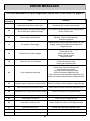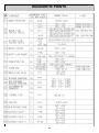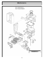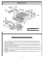
1
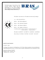
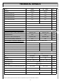
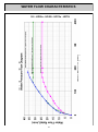
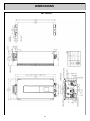
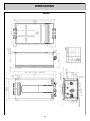
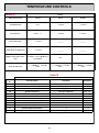
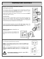
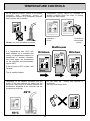
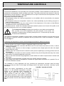
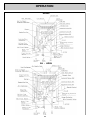
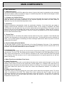
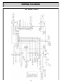
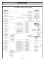
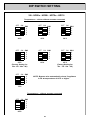
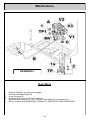
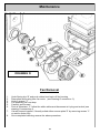
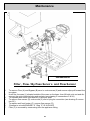
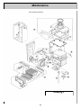
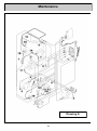
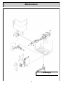
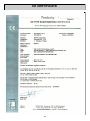
Service Manual
REU-VR2632FFUD - 26i
REU-VR2632 FFU-HD-E- HD50i
Continuous Flow Water Heater
Important.
Read these instructions carefully before attempting installation or use of this
appliance.
All work must be carried out by competent persons.
The Rinnai range of water heaters, when
correctly installed, comply with the
requirements of the United Kingdom
Water Regulations / Byelaws (Scotland).
These Products can be found listed in the
Water Fittings and Materials Directory.
The Rinnai water heaters are CE Marked as allowed by Technigas
26i - REU-VR2632FFUD-E
HD50e - REU-VR2632WDHD-E
HD50i - REU-VR2632FFUDHD-E
HD70e - REU-VRM3237WHD-E
HD70i - REU-VRM3237FFUHD-E
Certificate numbers: E0841/5386 Rev.5 - E0716/5360 Rev.05
E1061/5498 Rev.1 - E1060/5498 Rev.1
ID number: 0461BP0795 - 0461BO0739 - 0461BS0903 - 0461BS0903
Date of Issue: 23/12/2004 - 28/07/2003 - 26/10/2007 - 26/10/2007
Quality System Standard
ISO 9001 - 2000
The Design, Development, and Manufacture of Gas Water Heating Appliances done under Rinnai’s
Quality Management System is certified under the Quality Management System Standard ISO 9001.
Registration Number JQ0003D
Registered since: February 1994
Certified by JIA—QA Centre.
2
This manual is intended for use by Gas Safe
Registered Engineers
November 2012
3
CONTENTS
CONTENTS……………………………………………………………………………..…………………3
4
Glossary of Terms and Symbols
5
FEATURES AND BENEFITS
Rinnai water heaters will NEVER RUN OUT of hot water. As long as electricity, water, and gas
supplies are connected, hot water is available when hot water taps are open.
Built into the main micro-processor is the facility to LIMIT THE MAXIMUM TEMPERATURE of the hot
water supplied. The water temperature may be set to various temperatures. This is particularly useful
when the hot water unit is installed where young children or the infirm may be using the hot water. If
required, the temperature can be changed via the dip switches on the PCB or with a localised
controller. For further information, please contact Rinnai.
Rinnai water heaters are powered flue appliances. This makes them COMPACT, saving both floor
and wall space.
The temperature of outgoing hot water is CONSTANTLY MONITORED by a BUILT-IN SENSOR. If
the temperature of the outgoing hot water rises to more than 3°C above the selected temperature the
burner is shut OFF and only turned ON again when the temperature falls to below the selected
temperature.
The burner lights automatically when the hot water tap is opened, and extinguishes when the tap is
closed. IGNITION IS ELECTRONIC, so there is no pilot light. When the hot water tap is off, no gas is
used.
Up to four external temperature controllers can be mounted remotely from the heater. One Standard
control is supplied with all appliances (except for HD range). The remote offers the following
additional features:
Localised temperature setting
Diagnostic information
Error Codes
‘Deluxe’ Temperature Controllers are an optional extra. These provide functions including Bath Fill,
Voice Prompt, and Clock Setting.
Temperatures selected at the controllers are retained in the SYSTEM MEMORY.
Operating NOISE LEVEL IS VERY LOW.
ERROR MESSAGES ARE DISPLAYED on the Temperature Controllers and Status Monitor,
assisting with service.
FROST PROTECTION device built in as standard providing a power supply is maintained
6
TECHNICAL DETAILS
Model
HD50e
26i - HD50i
Installation
External
Internal
G20 Nat Gas Press Low
1.29
1.75
mbar
G20 Nat Gas Press High
6.81
9.35
mbar
G31 Propane Press Low
2.21
2.36
mbar
G31 Propane Press High
11.2
11.1
mbar
Direct Forced Exhaust
Forced, Room Sealed
Flue System
Units
Temp. Range Controllers
37-46, 48, 50, 55, 60, 65, 75
°C
Temp. via dip switches
40, 42, 50, 55, 60, 65, 75, 85
°C
Ignition
Gas Consumption & Capacities min conditions
G20 Nat Gas: Input Qm: Hi/Hs | Useful output Pm
Direct Electronic Ignition
( Hi = net calorific value Hs = gross calorific value )
3.93/4.36 | 3.49
3.93/4.36 | 3.49
kW
0.42
0.42
m3/hr
4.01/4.36 | 3.49
4.01/4.36 | 3.49
kW
0.31
0.31
Kg./hr
G20 Nat Gas flow V
G31 Input Qm: Hi/Hs | Useful output Pm
G31 flow normal operating conditions Mm
Gas Consumption & Capacities nominal condit.
G20 Nat Gas: Input Qn: Hi/Hs | Useful output Pn
( Hi = net calorific value Hs = gross calorific value )
49.8/55.3 | 45.9
48.6/54.0 | 44.8
kW
5.27
5.14
m3/hr
50.9/55.3 | 45.9
49.7/54.0 | 44.8
kW
3.95
3.86
Kg./hr
G20 Nat Gas flow ref. conditions Vr
G31 Input Qn: Hi/Hs | Useful output Pn
G31 flow normal operating conditions Mn
Country of destination
GB/IE
Gas category and pressure
Type
I2H G20-20mbar / I3P G31-37mbar
A3 Outdoor
C13/33 Indoor
32
32
L/min
ON = 2.4* / OFF = 1.7*
ON = 2.4* / OFF = 1.7*
L/min
Max Flow
Min Operation Flow
Water Pressure (Pw )
1.4* - 10.0
Power Supply
Electric Consumption (normal/stand-by/anti-frost)
bar
230 V / 50 Hz
50 / 2 / 100
66 / 2 / 100
Watts
50
50
dB (A)
Noise Level
Ignition safety time TSAmax
4.2
Weight
23
* Minimum operation pressure and flow based on temperature set point and inlet water conditions.
7
Sec.
24
Kg.
WATER FLOW CHARACTERISTICS
26i - HD50e - HD50i - HD70e - HD70i
8
DIMENSIONS
26i - HD50i
9
DIMENSIONS
HD50e
10
TEMPERATURE CONTROLS
The purpose of a Temperature Controller is to enable the user to have localised control over the hot
water supply.
Used correctly, the hot water unit will supply hot water at the temperature selected, even when the water
flow is varied, or when more than one tap is used.
Adjustments to the operation of your hot water unit can be made with any of the Temperature
Controllers.
Each Temperature Controller can be individually programmed.
Up to four universal can be fitted with Rinnai water heaters. Universal Controllers allow temperature
selection only and one comes as standard with the water heater.
Deluxe Temperature Controllers are available as an optional extra.
These controllers have temperature selection, bath fill, voice prompt, and time clock functions.
When more than one universal Controller is used one may be set as the Master Controller to allow
temperatures above 50°C.
(ask Rinnai for more information)
Various water temperatures (°C) can be selected as follows:
Universal Controller:
37, 38, 39, 40, 41, 42, 43, 44, 45, 46, 48, 50°C
Master universal Controller:
37, 38, 39, 40, 41, 42, 43, 44, 45, 46, 48, 50, 55°C (60, 65°C HD)
Deluxe Bathroom Controller:
Hot Water Delivery: 37, 38, 39, 40, 41, 42, 43, 44, 45, 46, 48, 50°C
Bath fill Delivery: 37, 38, 39, 40, 41, 42, 43, 44, 45, 46, 47, 48°C
Deluxe Kitchen Controller:
37, 38, 39, 40, 41, 42, 43, 44, 45, 46, 48, 50, 55°C (60, 65°C HD)
If a temperature of 43°C or higher is selected on any controller and this temperature is then decreased
to below 43°C and increased again whilst the water is running, the maximum selectable temperature will
be 43°C. This provides additional safety for the user.
Suggested temperatures are:
Kitchen 50°C - 65°C**; Shower 39°C - 43°C; Bath fill 39°C - 45°C
** This temperature may not be available on all installations.
These temperatures are suggested starting points for selection. You may find higher or lower
temperatures are more comfortable. Maintaining lower temperatures helps to save energy. To obtain
water temperatures lower than 37°C simply add cold water.
When multiple temperature controllers are used they allow the temperature to be set from various
locations by pushing the transfer button which gives that controller priority over the system. The
temperature selected by the controller with priority will be available to all outlets.
11
TEMPERATURE CONTROLS
Remote temperature controllers provide control over the water temperature. Rinnai water heaters can
be operated with 1, 2, 3, 4 or no temperature controllers.
NOTE
Each time a button is pressed, a BEEP will sound. The BEEP sound can be muted by
depressing the Temperature Controller Up and Down buttons simultaneously for more than
3 seconds. This can be done for each Temperature Controller. To return to original
settings, repeat this step.
Safety features
Whilst the hot water tap is open, the following
safety features apply:
NOTE
Temperature selection cannot be transferred.
The temperature of the outgoing water
is constantly monitored by a built in
sensor.
If the temperature of the outgoing
hot water rises to more than 3ºC above the
selected temperature shown on the digital
display, or the preset limit if controllers are not
fitted, the burner will automatically go out.
The temperature set point on the controller
with priority can always be lowered, but the
set point can only be raised to 43°C.
Other controllers are unable to take priority or
change the delivery temperature of the water.
The red operation indicator will also go out.
The burner will ignite again once the outgoing
hot water temperature falls to that shown on the
digital display (or the pre-set limit of the Rinnai
heater).
If off, the controller cannot be turned on.
12
TEMPERATURE CONTROLS
Table A
Models
Information Given
MC91
MC70
BC100
All Maintenance
N/A
↓ + Power
↓ + Power
Error History
Power + ↑
↑ + Power
↑ + Power
Water Flow Rate
↑ + Power
________
________
Outlet Water Temperature
↓ + Power
________
________
Higher temperature Function
Transfer + Power Held for 5
sec till noise
N/A
Turn off PIP Noise
↑ + ↓ Held for 5 sec till
noise
↑ + ↓ Held for 5 sec till
noise
↑ + ↓ Held for 5 sec till
noise
Table B
Maintenance Monitor
Section
No.
O1
Information Given
Units Given
Data Range
Liter per Min
0 - ???
O2
Water Flow sensor Recognition (Flow Rate)
Water Outlet Thermistor Temperature
˚C
0 - ???
O3
Combustion Time
100 Hours ( eg. 6 = 600hours )
000 - ???
O4
Operation Frequency
Fan Frequency
100 ( eg. 6 = 600hours )
000 - ???
Hz
0 - ???
O6
Remote Control Connection
None
0-3
O7
Water Flow Servo Position Recognition
None
0-2
O8
Fan Current
10mA
0 - ???
O9
Inlet Water Temperature
˚C
0 - ???
10
Bath Fill Amount
Litre ( this counts the bath fill amount )
0 - ???
11
Heat Exchanger Exit Thermistor
˚C
0 - ???
12
By Pass Servo Position Recognition
Degrees
0 - ???
O5
13
TEMPERATURE CONTROLS
Using the Temperature Controllers
Adjusting Temperature
Press the ON/OFF button
on
a
temperature
controller after making
sure that water is not
flowing.
Simply press
the Hot Water
Temperature
Up or Down
arrow button
The system will become
active, the temperature
will default to 40°C and
the controller that turned
the system on will have
priority.
HOTTER
COOLER
The temperature setting
on the controller will light
up.
until the desired
temperature is
displayed on
the
digital
display.
Using Hot Water
To turn off your hot water system
To operate the heater, simply turn any hot water
tap on. This will automatically light the burner
providing hot water. The red IN USE indicator
will glow on the temperature controller.
During normal operation the system is left on.
To turn the system off simply press the ON/OFF
button on any temperature controller (where
fitted). This will shut the water heater down
completely including the temperature controller
digital display.
The Digital Monitor will go out.
If hot water taps are opened when the Rinnai is
off, cold water will flow from the taps.
If the system is to be left off over the winter be
sure to drain it down if there is a possibility of
freezing temperatures.
Using High Temperature Display Controllers
You will need to program the Master controller if you want to display and use
temperatures over 50°C. Programming only needs to be done on Master
universal controller; other universal controllers will not allow this.
Deluxe Kitchen controllers are supplied already programmed to allow high
temperatures.
STEP 1: On the Master controller only press and hold the Transfer and ON/
OFF buttons simultaneously (see Fig. 1) until a “beep” is heard (approx. 5
seconds).
Fig. 1
STEP 2: When the Primary controller is switched on it should be possible to select temperatures higher
than 50ºC. If not repeat STEP 1.
If the master controller is replaced, repeat STEP 1 above
for the new controller.
NOTE
14
TEMPERATURE CONTROLS
Using 2 or more universal Temperature Controllers.
Switching the system ON.
The hot water system and all controllers can be switched ON and OFF from
any controller by pressing the ON/OFF button as shown. When the system
is turned ON the water temperature display will be lit.
During normal operation the system is left ON. Do not push the ON/OFF
button when water is running.
Using hot water.
Ensure the system is switched On by verifying the temperature display is lit.
Ensure the local controller has priority by verifying the Transfer LED
indicator is lit. If it is not then press the Transfer button once. This gives the
local controller priority of temperature over the system.
Select the desired temperature using the Hot water temp. buttons. The
selected temperature will be displayed on all controller displays. This is the
water temperature which will be supplied from the heater.
Bathroom temperatures should be no
more than 50°C.
Open the hot water tap. The appliance will
be activated and the In Use indicator will
be lit.
Using 4 Universal Temperature Controllers.
You will need to activate the fourth controller.
STEP 1: On the Master controller press and hold the Transfer and
ON/OFF buttons simultaneously (see Fig. 2) until a “beep” is heard
(approx. 5 seconds).
Fig. 1
STEP 2: Check that the display on all Four controllers is lit and
displaying a temperature when switched on. If any ONE of the
controllers displays two dashes (see Fig. 1) in the display repeat
STEP 1.
If the master controller is replaced, repeat STEP 1
above for the new controller.
NOTE
Fig. 2
15
TEMPERATURE CONTROLS
Do not push the ON/OFF button on the Master
controller after transferring priority of
temperature selection to a Secondary controller
as the system will shut down.
Temperature priority cannot be switched to
another controller when the water is flowing
through the water heater.
X
Controller 1
in use
Do Not Turn OFF the Master Controller
Controller 2
cannot take
priority
Bathroom
If a temperature over 50°C has
been selected on a controller and
priority of temperature selection is
transferred to another controller,
then back again, the temperature
on the controller will automatically
drop to 50ºC.
Kitchen
Kitchen
If the set point is 50°C or less it will
not alter.
This is a safety feature.
Depending on the weather conditions and
length of the pipe between the heater and
tap in use, there may be a variation between
temperature displayed at the controller and
temperature at the tap.
the
the
the
the
Do not clean the control with solvents or
detergents.
Use only a soft damp cloth.
S
O
L
V
E
N
T
16
TEMPERATURE CONTROLS
General Information
Commercial installations do not generally have controllers installed. These installations usually have one
permanent set temperature that is constant at all times. The public should not have access to alter the
temperature in these situations. These installations do not require controllers as the temperature can be
set by a series of dip switches on the PCB.
Exceptions to this are the following:
1.Circumstances where the required temperature is not available with the dip switches (for example
41°C or 47°C).
2.Circumstances where the temperature needs to be raised periodically by the building occupant in
order to flush the system.
3.Domestic situations where the user needs control of the temperature of the water so that different
temperatures can be used at different outlets.
In situations such as 1 and 2 the controllers should be installed in places out of reach of the public, such
as in the maintenance room or in a locked cupboard.
NOTE
NEW
FEATURE
This Commercial Setting will allow the controller to come back on automatically
after a power cut at the temperature set point previous to the power cut,
regardless of whether water is flowing through the unit. This should only be used
for commercial installations.
The maximum temperature available on the primary universal remote controller is the set point on the
dip switches. If only one controller is installed it will not go beyond 50°C when first installed. To bypass
this see page 11.
Positioning the temperature controls, the following points should be taken into account:
Fit the controls out of reach of children (suggested height from the floor 1.5m).
Avoid positions where the controllers will become hot. Do not fit them near stoves or ovens, or above
radiators or heaters.
If possible, avoid exposure to direct sunlight or positions where bright lights will make the digital
display difficult to read.
Position away from areas where the controller will be prone to splashing by cooking products such as
oils and fats.
The temperature controllers are water resistant, however they should be positioned away from areas
where direct or persistent splashing could occur.
Refer to the local electrical wiring regulations current edition for location requirements in shower and
bath areas.
The cables to the temperature controller carry only 12VDC (extra low voltage).
When using more than one temperature controller the signal cable should be run in parallel. Do not
wire the controllers in series.
The installation in every application will vary, therefore the temperature controller cable has been
provided so that you may cut the length accordingly and fit the spade connectors, ensuring a good
connection.
Cables are simply ‘piggy-backed’ at the water
heater or at the primary temperature controller.
Polarity is not important when connecting the
cables, either colour wire can be connected to
either terminal at both the heater or primary
temperature controller. If more cable is needed any
cable with similar specification to the cable supplied
with the controller can be used. Maximum length is
50m.
17
OPERATION
HD50e
26i - HD50i
18
MAIN COMPONENTS
1. Gas Control Unit
1.1 Modulating Valve
This device is used by the PCB to adjust the volume of gas to the burner in proportion to the volumetric
flow rate of water in order to maintain a supply of constant temperature hot water amid changes in water
flow rates and incoming temperatures.
1.2 Change-over Solenoid Valves
Additional solenoid valves are included to section the burner and stage the control in several steps. This
gives the burner more steady combustion at the required capacity and allows the water heater to
operate at very low flow rates and temperature rises.
2. Flame Rod
Monitors combustion characteristics inside the combustion chamber. If the flame fails, gas supply is
stopped. Works through rectification of the combustion flame. An AC voltage is supplied to the flame
rod. Electrons can only pass from the rod to the earthed burner through the flame, and never from the
burner to the rod, so the resultant DC current is used to prove combustion. When the DC current is
present the burner has normal combustion, if the DC current is not present (or an AC current is present)
the unit shuts the solenoid valve.
3. Thermal Fuse
The thermal fuse is an electric link which must be intact for the unit to operate. If the thermal fuse
reaches a set temperature it will melt and the unit will shut down. The thermal fuse must be replaced if it
melts. It is to protect against overheating and heat exchanger splits where water may leak out and be
superheated into steam.
4. Overheat Safety (Bi-metal Switch)
This Bi-metal Switch is fixed at the inlet bend of the Heat Exchangers final pass. If the temperature
outlet from the heat exchanger reaches 97°C the bi-metal switch will open and the solenoid valve circuit
is broken. This will cease combustion in case of overheat.
5. Combustion Fan
The combustion fan supplies primary air into the burner wings and secondary air up through the Bunsen
style burners. The fan is DC low voltage and the speed is controlled by the PCB depending on the hot
water supply and temperature. The fan speed is compared to the current required to attain that speed
for air proving. If the fan current is over or under the parameters for the given speed the unit will shut
down on air proving.
6. Water Flow Servo with Water Flow Sensor
6.1 Water Flow Sensor
Water flow sensing is done with a small turbine that spins when water travels through it in the correct
direction. Each of the four fins on the turbine has a small magnet on it. Outside of the valve there is a
magnetic sensor that detects the speed that the turbine is revolving. The revolution speed is input to the
PCB which relates this speed to the water flow volume and determines whether it is sufficient for
ignition.
6.2 Water Volume Flow Servo
Water flow control is achieved through the use of servo driven water flow and bypass valves. The servo
motor is controlled by the PCB. The ‘Water Flow Valve’ restricts the flow of water into the heat
exchanger assembly if the programmed temperature cannot be achieved. This will limit the maximum
water flow, and will limit the hot water flow further when the burner is at high fire to ensure the
temperature set point is met.
19
WIRING DIAGRAM
26i - HD50e - HD50i
20
FLOW CHART
26i - HD50e - HD50i - HD70e - HD70i
21
DIP SWITCH SETTING
Dip Switches Explained
Dip Switch Positions Explained
OFF ON SW1
1
2
3
4
5
6
7
8
-
Model Choice
Temperature
Temperature
Temperature
Temperature
Warm Water Switch
Forced Combustion
Forced Combustion
OFF ON SW2
1
2
3
4
5
6
-
Gas Type
Gas Type
Model Choice
Model Choice
Commercial Setting
Not in use (OFF)
FORCED COMBUSTION
NORMAL
OFF ON SW1
7 off
8 off
GAS TYPE
LPG
OFF ON SW2
1 off
2 off
LEGEND:
Black Section indicates position of dip switch:
OFF ON
HD50e
OFF ON SW1
1 on
SW2
3 off
4 on
ON
WARM WATER SWITCH
If activated reduces the min flowrate to light
OFF ON SW1 Rinnai when inlet water
6
temperature is close to
setpoint temperature
OFF = +3°C (default setting)
ON = Infinity off when outgoing temp +6°C
COMMERCIAL SETTING
OFF ON
FORCED LOW
OFF ON SW1
7 on
8 off
SW2 OFF = No Autoreset
5
ON = Autoreset
FORCED HIGH
OFF ON SW1
7 on
8 on
NOT IN USE
Switch nr.6 of SW2 is always "off" position
NATURAL GAS
OFF ON SW2
1 on
2 off
MODEL CHOICE
HD70e
OFF ON SW1
1 off
SW2
3 off
4 off
OFF ON
OFF
OFF ON SW2
6
HD70i + Long Flue
OFF ON SW1
1 off
SW2
3 on
4 off
HD70i + Short Flue
OFF ON SW1 (Factory setting)
1 on
SW2
3 on
4 off
26i / HD50i + Long Flue
OFF ON SW1
1 off
SW2
3 on
4 on
26i / HD50i + Short Flue
OFF ON SW1 (Factory setting)
1 on
SW2
3 on
4 on
22
DIP SWITCH SETTING
26i - HD50e - HD50i - HD70e - HD70i
Temperatures - with or without remotes connected
OFF ON SW1
2
3
4
5
40°C
OFF ON SW1
2
3
4
5
OFF ON SW1
2
3
4
5
42°C
OFF ON SW1
2
3
4
5
55°C
(Factory Setting for:
32e - 32i - 26e - 26i)
OFF ON SW1
2
3
4
5
OFF ON SW1
2
3
4
5
60°C
50°C
OFF ON SW1
2
3
4
5
65°C
(Factory Setting for:
70e - 70i - 50e - 50i)
NOTE: Bypass valve automatically closes if appliance
is set at temperatures of 60°C or higher.
75°C
Temperatures - without remotes connected
OFF ON SW1
2
3
4
5
85°C
23
TESTING
1.Purge gas, hot water and cold water supply lines before making the final connection of the water
heater. Swarf in either the gas or water supplies may cause damage.
2.Turn on gas and cold water supplies.
3.Test for water leaks and gas escapes near the unit.
4.Isolate gas and electric supply. Remove test point screw located on the inlet gas pipe work below the
heater and attach pressure gauge.
5.Turn the power on at the switch and turn on gas. Warning: There are 230V AC live supplies inside
the heater.
6.If remote controllers are fitted, turn the controller on, select the maximum delivery temperature and
open ALL available hot water outlets. If remote controllers are not fitted, simply open all available hot
water outlets. (CAUTION: Ensure building occupants do not have access to hot water outlets during
this procedure).
7.The gas pressure check must be carried out with all other appliances on the same main operating at
maximum capacity to ensure that there is sufficient gas pressure.
8.With all appliances on the same main operating at high fire check the pressure at the test point on
the inlet to the gas valve. The pressure must be within the local defined limits for the type of gas that
is being used. If the pressure is lower, the gas supply is inadequate and the water heater will not
operate to specification. Check gas meter, regulator and pipe work for correct operation/sizing and
rectify as required. Note that the gas regulator on the appliance is electronically controlled and
factory pre-set. Under normal circumstances it does not need adjustment during installation.
UK: the gas pressure must be at least 20 mbar and no more than 21 mbar for G20 Natural
Gas as used in UK. For G31 Propane as used in the UK the pressure must be at least 34.5
mbar and no more than 37 mbar.
9.Close hot water outlets.
10.Inspect and clean the strainer and the filter located on the cold water inlet pipe. This procedure may
need to be repeated to ensure the strainer remains clear.
11.If temperature controllers are fitted, it is necessary to test their operation through the complete range
of functions.
12.Confirm the hot water delivery temperature using a thermometer. If controllers are fitted, compare
the measured value to the set point.
13.After testing is completed, explain to the user the functions and operation of the water heater and
temperature controllers.
24
GAS PRESSURE SETTING
The working gas pressure on the water heater is electronically controlled and factory set. Under normal
circumstances it does not require adjustment during installation. The pressure should be checked
when the unit is installed and each time it is serviced to ensure that it is correct.
Contact Rinnai before attempting to alter the gas pressure if you are unsure of what to do.
Incorrect adjustment can void the warranty.
1.
Turn 'OFF' the gas supply.
2.
Turn 'OFF' 230V power supply.
3.
Remove the front cover from the appliance.
4. Check gas type dip switches no.1 and no.2 of SW2 are in the correct position for the type of gas
used. See Fig. 1
5. Attach pressure gauge to burner test point. (Fig. 2)
26 liters
32 liters
6.
Turn 'ON' the gas supply.
7.
Turn 'ON' 230V power supply.
8.
If remote controllers are fitted, turn the unit 'ON' at the controller and select a maximum delivery
temperature.
9. Open a hot water tap fully. (CAUTION: Ensure building occupants do not have access to hot
water outlets during this procedure.) Wait for the unit to light.
NOTE
* Simply changing the position of the dip switches will not convert the
unit from one gas type to the other. The conversion procedure requires
a change of injector manifold. Contact Rinnai or your supplier.
25
GAS PRESSURE SETTING
10. Set the Rinnai to 'Forced Low' combustion by setting No.7 dip switch
of SW1 to 'ON'. (Fig. 3)
11. Check the burner test point operating pressure.
LOW
GAS
HD50e
HD70e
26i
HD70i
HD50i
NG
G20
1.29
1.83
1.75
1.86
LPG
G31
2.21
2.34
2.36
2.22
Fig. 3
(pressures in mbar)
12. Remove rubber access plug and adjust the regulator screw on the
modulating valve (Fig. 4) as required to the pressure above.
Replace rubber access plug and seal it shut.
13. Set the Rinnai to 'Forced High' combustion by setting No.7 and
No.8 dipswitches to 'ON' (Fig.5). Ensure maximum water flow.
Fig. 4
Fig. 4
14. Check the burner test point pressure.
MAX
GAS
HD50e
HD70e
26i
HD50i
HD70i
NG
G20
6.81
7.95
9.35
7.95
LPG
G31
11.2
9.25
11.1
9.25
Fig. 5
(pressures in mbar)
15. Adjust the High Pressure Potentiometer on the Printed Circuit Board
SW1 (Fig. 6) to the pressure shown above. The potentiometer is very
sensitive, turn no more than a few degrees at a time; then let the
pressure settle down before turning it more.
16. IMPORTANT: Set dip switch No.7 and No.8 of SW1 to 'OFF' to return
the appliance to 'Normal' combustion.
17. Close hot water tap and turn ‘OFF’ the gas supply and 230V power
supply.
18. Remove pressure gauge and replace sealing screw.
Turn ‘ON’ the gas supply and power.
19. Operate unit and check gas leaks.
20. Replace the front cover of the appliance.
26
Fig. 6
ERROR MESSAGES
Troubleshooting without controllers
If you have not installed temperature controllers and experience the following symptoms, please carry
out the suggestions below. If symptoms continue, please contact Rinnai for advice.
NOTE: Faults caused by insufficient gas/water supply or gas/water quality and installation errors are
not covered by the manufacturer’s warranty.
Fault
Remedy
Heater does not attempt Check the power is on at the heater.
to start at all.
Check the cold water valve supplying the heater is open.
Heater starts then shuts Check the power is on. Open the hot water tap fully.
down immediately.
Check the gas valve at the heater and at the gas meter is fully open.
Heater starts then water
Check the power is on. Open your hot water tap further or try another hot outlet.
goes cold.
Installations with circulation pumps
With temperature controller fitted.
If you have an installation using a secondary circulation pump this must be switched off so that there is
no flow through the heater when starting or after a power failure. If the pump is running the unit will not
operate (no display on the controller). Isolate pump then start heater before restarting pump. This is a
safety feature. The pump should also be fitted with a timer to prevent the consumption of energy while
the building is not used. The timer should bring the system back on at least one hour before it is to be
used.
Without temperature controller fitted.
The heater should automatically reset and provide water at the temperature set by the internal limit
switches.
RESTARTING THE RINNAI WATER HEATER
Standard system.
Single or multiple water heaters without remote controllers.
The heaters will automatically reset without any user involvement.
Single or multiple water heaters with remote controllers.
The heaters will be required to be switched on using the ON/OFF button on a remote controller.
Ensure that all taps/water outlets are closed and no water is flowing through heaters.
Hot water system incorporating secondary recirculation pump.
Single or multiple water heaters without remote controllers.
The heater(s) will automatically reset without any user involvement.
Single or multiple water heater(s) with remote controller(s).
To reset the heaters follow the steps.
1. Turn off all hot water taps.
2. Turn off supply to secondary circulating pump or alternatively, isolate pump flow.
3. Turn on heater at remote control.
4. Select required temperature.
5. Switch on supply to secondary circulating pump or open valve on pump flow.
The heater will now be ready to supply water at the set temperature.
If following the above procedure does not reset the heater switch it on and off at its main supply, and
then go through these steps again. If heater is still not working call your local service agent or Rinnai for
assistance.
27
ERROR MESSAGES
For extra assistance in Fault Diagnostics follow the FLOW CHART of page 21
Code
Displayed
Fault
Remedy
-
Noticeable reduction in water flow
Inlet water filter needs to be cleaned.
03
Power interruption during operation (water
will not flow when power returned)
Turn off all hot water taps and circulating pumps.
Press ‘On/Off’ twice
10
Not enough combustion air
Check for physical blockages around air intake or
exhaust. Check combustion fan.
Diagnostic page 29
11
No Ignition / Gas supply
Check Burner Pressure p25 gas valves p32, gas
supply, ignition & ionisation electrodes p31
Diagnostic p29
12
Flame failure / Earth Leakage
Check gas valves and gas supply.
Check flame rod.
Check earth wire lead.
Check remote control.
Diagnostics p29
14
Thermal Fuse & or Overheat
Check Overheat circuit inc Thermal link p29
Check dip switches p22
Check gas Pressures p26
Check Gas Type dip switches p22
Check gas pressure p26
Check flow servo diagnostic p29
Check flow sensor diagnostic p29
Check Heat ex outlet thermistor diagnostic p29
Check Hot Water outlet thermistor diagnostic p29
16
Over temperature warning
32
Outgoing water temperature sensor faulty
Check Hot Water outlet thermistor diagnostic p29
33
Heat exchanger outlet sensor faulty
Check Heat ex outlet thermistor diagnostic p29
34
Combustion Air Temperature Sensor faulty
Check Thermistor p34 Diagnostic p29
52
Gas modulating valve faulty
Check Gas valve p32 Diagnostic p29
61
Combustion fan failure
Check fan p34 Diagnostic p29
65
Water flow control faulty, Water flow not
controlled or temp too low
Check Water Flow Servo p35 Diagnostic p29
71
Solenoid Circuit error
Check Gas valve p32 Diagnostic p29
72
Flame rod circuit error
Check electrode p32 Diagnostic p29
LC (00)***
Scale build-up in heat exchanger
De-scale or Replace Heat Exchanger
28
DIAGNOSTIC POINTS
29
Maintenance
DRAWING A
30
Maintenance
SERVICE PROCEDURE
To carry out a full service on this appliance the following has to be carried out:1.
2.
3.
4.
5.
6.
7.
8.
9.
10.
11.
12.
13.
14.
15.
16.
The Injector manifold should be removed, inspected and cleaned if required
( see page32)
The combustion chamber plate removed and both ignition and ionisation electrodes inspected and cleaned ( see page 32 )
Remove complete burner box visually inspect and clean if required, playing particular attention to where the ignition electrode sparks to ( see page 32 )
Visually inspect combustion chamber and up onto base of heat exchanger,
check for leaks, soiling of fins ect.
Remove fan assembly being careful of the air thermistor ( see page 34 )
Inspect impellor and clean if required ( See Page 34 )
Rebuild fan
Replace burner box
Replace combustion chamber cover
Replace manifold ensuring `O` rings on gas valve are securely in place and not
damaged, see drawing C `O` rings 1
Remove sealing screw on test nipple,TP1 on gas valve ( see page 33 ) and fit
manometer
Turn as many taps on as possible, or get as much water flowing through the
heater as possible
Once the flame is stable go through gas pressure setting procedure as per
pages 25 –26
Once burner pressures are set, turn off water flow
Remove manometer and replace TP1 sealing screw
Turn on flow of water and when unit has fired check for any gas leaks.
Care
When the appliance casing, operation panel, and remote controls surfaces become
dirty gently wipe them clean with a soft, damp cloth. Do not use detergents on these
parts.
Filter
The water heater has a filter on the cold water inlet connection. This filter will need to
be cleaned occasionally. How often will be determined by the local water conditions;
contact Rinnai or ask your installer for information.
Isolate the cold water inlet and hot water outlet with the valves near the heater. Release the pressure in the heater by unscrewing the drain valve. Then remove the filter, clean it and replace it.
31
Maintenance
DRAWING B
Manifold & Burner Box Removal
1.
2.
3.
4.
5.
To remove Manifold (A) undo all 9 screws (1) then pull forward, disconnect solenoid ( see
drawing G connection 2A) Inspect injectors if required remove front plate off manifold and
clean injectors outwards
Remove Combustion Chamber Plate (B) by undoing all screws (2) and clean ignition and Ionisation electrodes, to remove these undo screws (3) PRIOR TO CARRYING THIS OUT ENSURE YOU HAVE THE GASKET
To remove burner box undo 2 screws (4) on plate C this will now allow full burner box to be
withdrawn and the burners to be cleaned ( turn upside down and shake and blow through with
air brush)
If any burner wings (D) are damaged remove bracket (E) by undoing screw (5) and pull damaged wing out and replace
To Rebuild reverse above ENSURING `O`RINGS ARE INTACT AND IN PLACE ON GAS
VALVE
32
Maintenance
DRAWING C
Gas Valve
1.
2.
3.
4.
5.
6.
Remove Manifold as per previous page
Disconnect breather pipe (B)
Undo 4 screws (2)
Grasping Gas Valve (A) lift up and pull out
Disconnect all solenoids V1, V2, V3 & MV (see drawing G connection (2) )
Refit in reverse order ENSURING `O`RINGS (1) ARE INTACT AND IN POSITION
33
Maintenance
DRAWING D
Fan Removal
1.
2.
3.
4.
5.
6.
7.
8.
Undo Spring clip `B` and push rubber boot back off fan housing
Disconnect wiring plug from fan motor (see Drawing G connection 3)
Undo 2 screws `1`
Fan assembly will now drop
Carefully pull forward
Find air thermistor `C` follow the white cables and disconnect at it plug and socket (see
drawing G connection 4)
Visually inspect impellor, if heavily soiled either remove plate`D` by removing screws `2`
or remove motor fully
Once completed cleaning reverse the above procedure
34
Maintenance
DRAWING D
DRAWING E
Filter , Flow / By Pass Servo`s and Flow Sensor
1.
2.
3.
4.
5.
6.
7.
To remove Flow (A) and Bypass (B) servo`s undo screws (2) and remove clips pull forward the
two pipes
Undo the 4 screws (1) situated outside of the case on the base then lift both units out and disconnect the units individual plug and sockets (see drawing G connections 5 & 5A)
To separate both units undo screws (3) and pull apart
To remove flow sensor (D) undo screw (3) and un plug its connection (see drawing G connection 5C)
To replace anti frost heater (C) remove flow sensor (D)
Reverse to re-build ENSURE `O` Ring `E` IS IN PLACE
Filter (F) is removed by unscrewing from the appliance fitting
35
Maintenance
Drawing F
36
Maintenance
Drawing G
37
Maintenance
Drawing H
38
Maintenance
To Remove Heat Exchanger
As each item is removed keep the relevant screws with that item
DRAWING F
1.
2.
. Remove assembly `A` (see Manifold & Burner Box Removal page 39)
Remove assembly `B` (see Fan Removal page 41)
1.
Disconnect Heat Exchanger Pipes, undo screws `A` from plates `1` and spin plates out of the
way and remove plates.
Pull the 2 cold feed pipes `2` from out of the by pass servo
Pull Hot feed pipe `3` from it`s housing.
Undo 2 PCB securing screws and pull out PCB and leave hanging picture H screws C
DRAWING H
2.
3.
4.
DRAWING G
1.
2.
3.
4.
Unclip anti frost heaters,items 1A,1B, 1C and leave hanging outside the case.
Unclip the Thermal link ,connection 6
Disconnect Heat Exchanger Thermistor, connection 7
Disconnect Sparker connection, connection 8
DRAWING F
1.
2.
3.
4.
5.
Disconnect breather pipe from gas valve, item H
Undo screw below air box screw d
Undo 3 screws under fan bracket on base of heat exchanger, screws c
Undo 2 screws top left hand corner of heat exchanger, screws a
Whilst supporting heat exchanger assembly, remove 2 screws top right hand side of heat exchanger, screws b
6.
Remove complete heat exchanger
7.
Unclip remove over heat stat and thermal fuse from around heat exchanger, item F
8.
Remove heat exchanger thermistor ensuring the `O` ring is not left in place, item E
9.
Remove sparker from base of heat exchanger, item G
10. Undo screws from cover of air box, item H screws f
11. Remove side box and top of air box
12. Undo screws holding base of air box onto the top of the heat exchanger, screws e
To Rebuild New Heat Exchanger
Reverse the above instructions placing all components onto new heat exchanger.
NOTE
ENSURE NEW `O` RINGS SUPPLIED WITH NEW HEAT EXCHANGER
ARE FITTED ONTO THE PIPE see drawing H `O` rings `B`
39
LETTER OF COMPLIANCE
40
CE CERTIFICATE
41
CE CERTIFICATE
42
COMMISSIONING CHECK LIST
43
UK WARRANTY
As the purchaser of this high quality Rinnai Water Heater you are provided with the following conditional warranty.
Heat Exchanger
All Other Parts
Parts
Labour
Parts
Labour
Standard Use
3 Years
1 Year
3 Years
1 Year
Commercial Use
5 Years
1 Year
5 Years
1 Year
Rinnai 26i
HD50e / HD70e
HD50i / HD70i
Definition of Standard Use.
The warranty period allocated under Standard Use is based on Domestic and Light Commercial hot water usage.
Rinnai Standard Use warranty periods apply only where Rinnai water heaters are installed in domestic and light
commercial situations at operating temperatures below 65°C and do not include installations incorporating storage
cylinders or building flow and return systems.
The warranty shall apply to any Rinnai water heater.
Definition of Commercial Use.
The warranty period allocated under Commercial Use are for Rinnai water heaters installed at premises such as
commercial and industrial buildings, cafes, caravan parks, and sporting complexes. Commercial Use warranty applies to:
Water heaters supplying a central shower block.
Water heaters supplying kitchens used for the bulk preparation of food.
Water heaters set to 65°C or higher.
Water heaters used in commercial or industrial processes.
Any application that uses Rinnai water heaters in conjunction with storage tanks.
Any application that uses Rinnai water heaters in conjunction with a flow / return system.
Water heaters installed as components of centralised bulk hot water systems.
Rinnai units used in Commercial Situations are only subject to a 1 year warranty across the board.
No Rinnai warranty will cover damage/ faults arising from moving or storing the unit; improper installation or gas
supply; water contaminants beyond defined limits; environmental factors; plumbing fittings, or other outside influences of which Rinnai is not responsible. Service calls for these issues will be chargeable.
The unit must be serviced annually to validate the warranty.
The warranty period begins on customer’s date of purchase.
Description
pH
Maximum
Recommended 6.5 - 9.0
Levels
Total Dissolved
Total Hardness Chlorides Magnesium Calcium Sodium
Solids (TDS)
Iron
300 mg/
litre
1 mg/
litre
600 mg/litre
150 mg/litre
44
10 mg/litre
20 mg/ 150 mg/
litre
litre
UK WARRANTY
WHAT IS COVERED?
This Warranty covers any defects in materials or workmanship when the product is installed and
operated according to Rinnai installation instructions, subject to the terms within this limited warranty
document. This Warranty applies only to products that are installed by a registered gas engineer.
Improper installation may void this Warranty. This Warranty extends to the original purchaser and
subsequent owners, but only while the product remains at the site of the original installation. This
Warranty only extends through the first installation of the product and terminates if the product is moved
or reinstalled at a new location.
WHAT WILL RINNAI DO?
Rinnai will repair or replace the product or any part or component that is defective in materials or
workmanship, except as set forth below: All repairs must be performed using genuine Rinnai parts. All
repairs or replacements must be performed by a registered gas engineer. Replacement of the product or
replacement of the heat exchanger may only be authorised by Rinnai. Rinnai does not authorise any
person or company to assume for it any obligation or liability in connection with the replacement of a
product or heat exchanger. If Rinnai determines that repair of a product is not possible, Rinnai will
replace the product with a comparable product, at Rinnai’s discretion. If a component or product
returned to Rinnai is found to be free of defects in material or workmanship, or damaged by improper
installation the warranty claim may be denied.
HOW DO I GET SERVICE?
Contact your supplier or Rinnai UK.
Proof of date of purchase is required to obtain warranty service. You can show proof of purchase with a
dated invoice or by completing and returning the enclosed Warranty registration card.
Receipt of warranty registration by Rinnai will constitute proof-of-purchase for this product. However,
Warranty registration is not necessary in order to validate this Warranty.
WHAT IS NOT COVERED?
This Warranty does not cover any failures or operating difficulties due to accident, abuse, misuse,
alteration, misapplication, acts of God, improper installation, improper maintenance or service,
inadequate water quality, scale buildup, freeze damage or for any other causes other than defects in
materials or workmanship. This warranty does not apply to any product whose serial number or
manufacture date has been defaced.
This Warranty does not cover any product when used as a pool or spa heater.
Rinnai is not liable for any special, incidental, indirect or consequential damages that may arise,
including damage to person or property, loss of use, failure to install drain pan under unit, or
inconvenience.
This warranty does not effect your statutory rights as defined in the UK.
45
CONTACT
UK LTD.
9 Christleton Court
Manor Park
Runcorn
Cheshire
WA7 1ST
Tel. 01928 531870
Fax. 01928 531880
E-mail. [email protected]
Web.
www.rinnaiuk.com
HEATER DETAILS
Model Number _____________________________________________
Serial Number _____________________________________________
Date of Purchase _____________________________________________
46
47
RUK Tech Dept. v1 Dec 2012 IJ
48