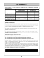
1
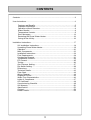
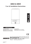
Installation and User Manual
REU-KM3237FFUD-E
Infinity Condensing 32i
REU-KM3237WD-E
Infinity Condensing 32e
REU-KM3237FFUDHD-E
Infinity HDC 1500i
REU-KM3237WDHD-E
Infinity HDC 1500e
Continuous Flow Water Heater
Important.
Read these instructions carefully before attempting installation or use of
this appliance. All work must be carried out by competent persons.
The Rinnai Infinity range of
water heaters, when correctly
installed, comply with the
requirements of the United
Kingdom Water Regulations /
Byelaws (Scotland). These
Products can be found listed in
the Water Fittings and Materials
Directory.
The Rinnai Infinity condensing 32i
and condensing 32e water heaters are
CE Marked as allowed by Technigas.
Certificate number:
ID number:
Date of Issue
Quality System Standard
ISO 9001 - 2000
The Design, Development, and Manufacture of Gas Water Heating Appliances
done under Rinnai’s Quality Management System is certified under the Quality
Management System Standard ISO 9001.
Registration Number JQ0003D
Registered since: February 1994
Certified by JIA—QA Center.
2
CONTENTS
Contents………………………………………………………………..…………………3
User Instructions.....................................................................................................4
Features and Benefits………………………………………………..………….5
Important Information…………………………………………...……..………..6
Operation without Remotes……………………………………………….……8
Status Monitor..............................................................................................8
Temperature Controls…………………………………………….…………..…9
Error Messages…………………………………………………………………14
Restarting the Rinnai Water Heater………………………………………….16
Caring for the Infinity……...……………………………………………………16
Installation Instructions…………………………………………….………..…………17
UK Installation Instructions…………………………………………………….18
Unpacking Rinnai Water Heater…………………………….………………...19
Operation ..............……………………………………………...……………...20
Main Components………………………………………………..……………..22
Installation Instructions……………………………………………….………...23
Flue Requirements……………………...…….………………………………..28
Condensate Disposal…………………………………………………………...31
Temperature Controls…………………………………………………………..33
EZ Connect.................................................................................................35
Testing…………………………………………………………………......…….36
Gas Pressure Setting…………………………………………………….....….37
Dip Switch Setting………............……………………………………………...39
Dimensions…………………………...........................………………………..41
Technical Details..……………………………………............………………...42
Flow Chart…….………………………………………………......………..……43
Wiring Diagram…….……………………………………………………………44
Diagnostic Points…………………………………………………………….....45
Water Flow Characteristics.........................................................................46
Letter of Compliance……………………………………………………....…...47
CE Certificate……………………………..……………………………………..48
Commissioning Checklist…………………...………………………………….49
UK Warranty………………………………….………………………………….50
Specification................................................................................................52
Contact........................................................................................................53
Heater Details.............................................................................................53
3
USERS INSTRUCTIONS
The following instructions are designed for the user of the water heater. The user may
not install or adjust the appliance in any way that requires the removal of the front cover
of the unit. To remove the front cover of the unit you must be certified competent to do
so. Information for the Installer is given on page 17.
All work done on this appliance must be done by a qualified gas
engineer. A qualified gas engineer must carry an up to date CORGI
Registered Gas Installer photo identification card while working on gas
appliances. If you are unsure do not be afraid to ask the engineer to
show you the card. If you are still not satisfied call CORGI on 0870 401
2300 and verify the engineer’s name with their database. This is for your
own safety.
Responsibilities of the USER
The user must abide by all warnings given in this book. The user must only reference
the user section of the book, and may not carry out any procedure listed in the installer
section. This installation manual should be kept with the appliance for maintenance and
user information.
The user must have the unit checked and maintained annually by a gas engineer.
The user must periodically check the water filter on the inlet to the appliance.
The user must not use the appliance in any way that it was not meant to be used. The
user may only use the heater as detailed in the User portion of this manual.
Interference with a sealed component is not permitted
Conversion to other gas types should only be carried out by a qualified installer or a gas
distributor according to the practice in the country where the unit is installed.
The user must not store or use any flammable vapours or liquids in the vicinity of this or
any other appliance.
The user should familiarise themselves with the water heaters gas service valve and the
main gas valve to the premises.
IF YOU SMELL GAS
Isolate the gas supply and get out of the building.
Do not try to light any appliance.
Do not turn any light or other electrical switch on or off.
Do not use any telephone in the building.
Call your gas engineer from a safe location and follow their
instructions.
If you cannot reach your gas engineer ring the following:
National Grid 0800 111 999
4
FEATURES AND BENEFITS
Congratulations on purchasing the Technologically Advanced, Temperature Controlled,
Rinnai Hot Water System.
x Rinnai water heaters will NEVER RUN OUT of hot water. As long as electricity,
water, and gas supplies are connected, hot water is available when hot water taps are
open.
x Built into the main micro-processor is the facility to LIMIT THE MAXIMUM
TEMPERATURE of the hot water supplied. The water temperature may be set to
various temperatures. This is particularly useful when the hot water unit is installed
where young children or the infirm may be using the hot water. If required, the
temperature can be changed via the dip switches on the PCB or with a localised
controller. For further information, please contact Rinnai.
x Rinnai Infinity water heaters are powered flue appliances. This makes them
COMPACT, saving both floor and wall space.
x The temperature of outgoing hot water is CONSTANTLY MONITORED by a BUILT-
IN SENSOR. If the temperature of the outgoing hot water rises to more than 3°C
above the selected temperature the burner is shut OFF and only turned ON again
when the temperature falls to below the selected temperature.
x The burner lights automatically when the hot water tap is opened, and extinguishes
when the tap is closed. IGNITION IS ELECTRONIC, so there is no pilot light. When
the hot water tap is off, no gas is used.
x The Infinity Condensing 32i / HDC1500i and Condensing 32e / HDC1500e have a
built in Status Monitor on the front of the unit to display error codes and run
condition. Up to four external temperature controllers can be mounted remotely from
the heater. This offers the following additional features:
Localised temperature setting.
Diagnostic information.
Error Codes.
Clock
Bath fill
x ‘Deluxe’ Temperature Controllers are an optional extra. These provide functions
including Bath Fill, Voice Prompt, and Clock Setting.
x Temperatures selected at the controllers are retained in the SYSTEM MEMORY
x Operating NOISE LEVEL IS VERY LOW.
x ERROR MESSAGES ARE DISPLAYED on the Temperature Controllers, assisting
with service.
x FROST PROTECTION device built in as standard.
5
IMPORTANT INFORMATION
Excessively hot water is dangerous, especially for young children and the infirm. The
water heater allows you to control the temperature of your hot water to safe levels.
Water temperature over 50ºC can cause severe
burns instantly or even death from scalding.
Children, disabled and the elderly are at the
highest risk of being scalded by excessively hot
water.
Always test the temperature of the water before
bathing or showering.
Burns from hot water taps can result in very
severe injuries to young children.
Hot water at 65°C can severely burn a child in less
than half a second. At 50°C it takes five minutes.
Burns can occur when children are exposed
directly to hot water or when they are placed into a
bath which is too hot.
Do stay with children whenever
they are in the bathroom.
x Consider child—resistant taps
or inexpensive tap covers, both
of which prevent a child’s hand
from turning on the tap.
Do take them out of the bathroom if
you need to answer the phone or
door.
Do test the temperature of the water
with your elbow before placing your
child in the bath.
DO
x Consider reducing the
Do make sure that the tap is turned
off tightly.
Do consider setting your Rinnai
Water Heater at a maximum
temperature of 50°C.
Do install a child proof tap cover
OR,
Do install a child resistant tap.
DO
NOT
Do not leave a toddler in the care of
another small child. The older child
may not have safely set the temperature.
6
temperature of the water
supplied to the hot tap to 50°C.
This approach can be extremely
valuable because it requires a
one time action for a long term
reduction in risks of scalds.
This type of automatic protection
is important during times when a
parent or carer has been
distracted.
IMPORTANT INFORMATION
Always check water temperature before
use.
Hot water may go cold without warning at
very low water flows (less than 3 l/min.)
OFF!
Refer to warning about hot water on
page 6 for important safety information.
The delivered water temperature is
controlled automatically. The water from
the hot tap may be reduced after the
temperature shown on the remote control
is raised. The water flow may also vary
with the temperature of the incoming
water supply.
43°C
If freezing temperatures are expected, turn
off the water and gas, and drain the water
heater.
Turn Water Off
Filter
55°C
Drain
Gas
Valve
Turn Gas Off
Drain Water
Hot Cold
Gas
If the power is left on the Automatic Frost Protection
will prevent the unit from Freezing. Frost protection
is standard on all units.
Keep flammable materials, trees, shrubs,
chemicals, etc. away from the flue outlet /
terminal.
Do not touch the flue outlet. Do not insert
objects into the flue outlet / terminal.
HOT!
On cold days steam may be discharged
from the flue outlet. This is normal, do
not be alarmed. It does not indicate a
fault.
Do not spray water into flue terminal
7
OPERATION WITHOUT REMOTES
Rinnai Infinity products have no pilot light and operate automatically as soon as water flow is
sensed.
The burner ignites with electronic ignition and the flame extinguishes as soon as water
flowing through the appliance stops.
Turn On by opening the hot water tap
OFF!
HOT
NOTE
ON!
COLD
OFF!
COLD
ON!
HOT
The Rinnai Infinity range of water heaters are factory preset to a
temperature of 55°C; the HD range are preset to 65°C. Other limits, lower or
higher, are available on request. Temperature controllers are available to
allow precise digital temperature control. Controllers can be installed at any
time after installation of the hot water unit.
Excessively hot water is dangerous. Rinnai water heaters allow you to
control the temperature of your hot water to a safe level.
Water temperatures above 50°C can cause severe burns instantly, such
scalding may even result in death. Those most at risk are children,
CAUTION disabled, elderly and the infirm. Hot water at 65°C (a very common water
temperature in the UK) can severely burn a child in less than half a
second. At 50°C it takes five minutes.
Consider using Thermostatic Mixing Valves on the Hot Water Outlets.
STATUS MONITOR
The new series of Rinnai Water Heaters have a built in status monitor on the front.
STATUS MONITOR
The status monitor has three conditions:
1 - The water heater is off (no water flowing): the monitor is blank.
2 - The water heater is on (heating water): The monitor displays the set
temperature.
3 - The water heater should be on, but is not (water is flowing, heater is
not on): The monitor will display a flashing error code.
NEW FEATURE
8
TEMPERATURE CONTROLS
The purpose of a Temperature Controller is to enable the user to have localised control
over the hot water supply. Used correctly, the hot water unit will supply hot water at the
temperature selected, even when the water flow is varied, or when more than one tap is
used. Adjustments to the operation of your hot water unit can be made with any of the
Temperature Controllers. Each Temperature Controller can be individually programmed.
Up to four Universal and/or Deluxe Temperature Controllers can be fitted with Rinnai
water heaters. Universal Controllers allow temperature selection only and one comes as
standard with the water heaters. Deluxe Temperature Controllers are an optional extra.
These controllers have temperature selection, bath fill, voice prompt, and time clock
functions. When more than one Universal Controller is used one may be set as the
Master Controller to allow temperatures above 50°C.
Various water temperatures (°C) can be selected as follows:
Universal Controller:
37, 38, 39, 40, 41, 42, 43, 44, 45, 46, 48, 500C
Master Universal Controller:
37, 38, 39, 40, 41, 42, 43, 44, 45, 46, 48, 50, 55°C ( 60, 65°C HD )
Deluxe Bathroom Controller:
Hot Water Delivery: 37, 38, 39, 40, 41, 42, 43, 44, 45, 46, 48, 50°C
Bath fill Delivery: 37, 38, 39, 40, 41, 42, 43, 44, 45, 46, 47, 48°C
Deluxe Kitchen Controller:
37, 38, 39, 40, 41, 42, 43, 44, 45, 46, 48, 50, 55°C ( 60, 65°C HD )
If a temperature of 43°C or higher is selected on any controller and this temperature is
then decreased to below 43°C and increased again whilst the water is running, the
maximum selectable temperature will be 43°C. This provides additional safety for the
user.
Suggested temperatures are:
Kitchen 50°C - 65°C*; Shower 39°C - 43°C; Bath fill 39°C - 45°C
* This temperature may not be available on all installations.
These temperatures are suggested starting points for selection. You may find higher or
lower temperatures are more comfortable. Maintaining lower temperatures helps to save
energy. To obtain water temperatures lower than 37°C simply add cold water.
When multiple temperature controllers are used they allow the temperature to be set
from various locations by pushing the transfer button which gives that controller priority
over the system. The temperature selected by the controller with priority will be available
to all outlets.
9
TEMPERATURE CONTROLS - OPERATING
Remote temperature controllers provide control over the water temperature. Rinnai water
heaters can be operated with 1, 2, 3, 4 or no temperature controllers.
NOTE
Each time a button is pressed, a BEEP will sound. The BEEP sound can be
muted by depressing the Temperature Controller Up and Down buttons
simultaneously for more than 3 seconds. This can be done for each
Temperature Controller. To return to original settings, repeat this step.
The temperature of the outgoing
water is constantly monitored by
a built in sensor.
Safety features
Whilst the hot water tap is open, the
following safety features apply:
x Temperature
selection
cannot
NOTE
If the temperature of the outgoing
hot water rises to more than 3ºC above the
selected temperature shown on the digital
display, or the preset limit if controllers are
not fitted, the burner will automatically go
out.
be
transferred.
x The
temperature setpoint on the
controller with priority can always be
lowered, but the setpoint can only be
raised to 43°C.
The red operation indicator will also go out.
x Other controllers are unable to take
priority or change the
temperature of the water.
delivery
The burner will ignite again once the
outgoing hot water temperature falls to that
shown on the digital display (or the pre-set
limit of the Rinnai Infinity heater).
x If off, the controller cannot be turned on.
10
TEMPERATURE CONTROLS - OPERATING
Using the Temperature Controllers
Adjusting Temperature
Press the ON/OFF button on a
temperature controller after making sure
that water is not flowing.
Simply press the Hot Water Temperature
Up or Down arrow button until the desired
temperature is
displayed on
the
digital
display.
The system will become
active, the temperature
will default to 40°C and
the controller that turned
the system on will have
priority.
HOTTER
COOLER
The temperature setting
on the controller will light
up.
Using Hot Water
To turn off your hot water system
To operate the heater, simply turn any hot
water tap on. This will automatically light
the burner providing hot water. The red IN
USE indicator will glow on the temperature
controller.
During normal operation the system is left
on.
ON!
To turn the system off simply press the
ON/OFF button on any temperature
controller (where fitted). This will shut the
water heater down completely including
the temperature controller digital display.
COLD
The Digital Monitor will go out.
If hot water taps are opened when the
Rinnai Infinity is off, cold water will flow
from the taps.
If the system is to be left off over the winter
be sure to drain it down if there is a
possibility of freezing temperatures.
HOT
Using High Temperature Display Controllers
You will need to program the Master controller if you want to
display and use temperatures over 50°C. Programming only
needs to be done on Master universal controller; other universal
controllers will not allow this.
Deluxe Kitchen controllers are supplied already programmed to
allow high temperatures.
STEP 1: On the Master controller only press and hold the
Transfer and On/Off buttons simultaneously (see fig 1.) until a
“beep” is heard (approx. 5 seconds)
Fig 1.
STEP 2: When the Primary controller is switched on it should be possible to select
temperatures higher than 50ºC. If not repeat STEP 1.
If the master controller is replaced, repeat STEP
1 above for the new controller.
NOTE
11
TEMPERATURE CONTROLS - OPERATING
Using 2 or more Universal Temperature Controllers.
Switching the system ON.
The hot water system and all controllers can be switched ON
and OFF from any controller by pressing the On/Off button as
shown. When the system is turned ON the water temperature
display will be lit.
During normal operation the system is left ON. Do not push the
On/Off button when water is running.
Using hot water.
Ensure the system is switched On by verifying the temperature
display is lit. Ensure the local controller has priority by verifying
the Transfer LED indicator is lit. If it is not then press the
Transfer button once. This gives the local controller priority of
temperature over the system.
Select the desired temperature using the Hot water temp.
buttons. The selected temperature will be displayed on all
controller displays. This is the water temperature which will be
supplied from the heater.
Bathroom
temperatures
should be no more than 50°C.
ON!
COLD
Open the hot water tap. The
appliance will be activated and
the In Use indicator will be lit.
HOT
Using 4 Universal Temperature Controllers.
You will need to activate the fourth controller.
STEP 1: On the Master controller press and hold the
Transfer and On/Off buttons simultaneously (see fig 2.)
until a “beep” is heard (approx. 5 seconds)
Fig 1.
STEP 2: Check that the display on all Four controllers is lit
and displaying a temperature when switched on. If any
ONE of the controllers displays two dashes (see fig 1.) in
the display repeat STEP 1.
If the master controller is replaced, repeat
STEP 1 above for the new controller.
NOTE
Fig 2.
12
TEMPERATURE CONTROLS - INFORMATION
Do not push the ON/OFF button on the
Master controller after transferring priority
of temperature selection to a Secondary
controller as the system will shut down.
Temperature priority cannot be switched
to another controller when the water is
flowing through the water heater.
X
Controller 1
in use
Do Not Turn OFF the Master Controller
If a temperature over 50°C
has been selected on a
controller and priority of
temperature selection is
transferred to another
controller, then back again,
the temperature on the
controller will automatically
drop to 50ºC. If the set
point is 50°C or less it will
not alter. This is a safety
feature.
Controller 2
cannot take
priority
Bathroom
Kitchen
Depending on the weather conditions
and the length of the pipe between the
heater and the tap in use, there may be a
variation between the temperature
displayed at the controller and the
temperature at the tap.
Kitchen
Do not clean the control with
solvents or detergents. Use only a soft
damp cloth.
49°C
S
O
L
V
E
N
T
50°C
13
ERROR MESSAGES
Rinnai water heaters have the ability to check their own operation continuously. If a fault
occurs, an error code will flash on the Digital Display (and on the Status Monitor) if you
have temperature controllers installed. This assists with diagnosing the fault, and may
enable you to overcome a problem without a service call. Please quote the code
displayed when enquiring about service.
Code
Displayed
Fault
-
Noticeable reduction in water flow
03
Power interruption during operation
(water will not flow when power
returned)
Turn off all hot water taps and circulating
pumps. Press ‘On/Off’ twice
10
Not enough combustion air
Check for physical blockages around air intake
or exhaust. Check combustion fan.
11
No Ignition / Gas supply
Check gas valves, gas supply and sparker
unit.
12
Flame failure / Earth Leakage
Check gas valves and gas supply.
Check flame rod.
Check earth wire lead.
Check remote control.
14
High flame safety device
Service Call
16
Over temperature warning
Service Call
25
Condensate pipe blockage
Check for blockage on condensate drain path.
32
Outgoing water temperature sensor
faulty
Service Call
33
Heat exchanger outlet sensor faulty
Service Call
52
Gas modulating valve faulty
Service Call
61
Combustion fan failure
Service Call
65
Water flow control faulty (does not
stop flow properly)
Service Call
71
Micro-processor failure
Service Call
72
Flame rod circuit error
Service Call
LC (00)***
Scale build-up in heat exchanger
Service Call
Remedy
Inlet water filter needs to be cleaned.
* In all cases, you may be able to clear the Error code by turning the hot water tap OFF, then ON
again. If this does not clear the error, try pushing the On/Off button OFF then ON again. If the Error
Code still remains contact Rinnai or your nearest service agent for advice.
** Faults caused by insufficient gas/water supply or gas/water quality and installation errors are not
covered by the manufacturer’s warranty.
*** The display will alternate between temperature setting and LC code. The controller will continue to
beep. The LC code will reset if power is turned Off and then On.
14
ERROR MESSAGES
Troubleshooting without controllers
If you have not installed temperature controllers and experience the following
symptoms, please carry out the suggestions below. If symptoms continue, please
contact Rinnai for advice.
Fault
Remedy
Heater does not attempt Check the power is on at the heater.
to start at all.
Check the cold water valve supplying the heater is open.
Heater starts then shuts
down immediately.
Check the power is on.
Check the gas valve at the heater and at the gas meter is fully open.
Open the hot water tap fully.
Heater starts then the
water goes cold.
Check the power is on.
Open your hot water tap further or try another hot outlet.
NOTE: Faults caused by insufficient gas/water supply or gas/water quality and
installation errors are not covered by the manufacturer’s warranty.
Installations with circulation pumps
With temperature controller fitted.
If you have an installation using a secondary circulation pump this must be
switched off so that there is no flow through the heater when starting or after a
power failure. If the pump is running the unit will not operate (no display on the
controller). Isolate pump then start heater before restarting pump. This is a safety
feature.
The pump should also be fitted with a timer to prevent the consumption of energy
while the building is not used. The timer should bring the system back on at least
one hour before it is to be used.
Without temperature controller fitted.
The heater should automatically reset and provide water at the temperature set by
the internal limit switches.
15
RESTARTING THE RINNAI WATER HEATER
The heaters should be restarted in this manner.
Standard system.
Single or multiple water heaters without remote controllers.
The heaters will automatically reset without any user involvement.
Single or multiple water heaters with remote controllers.
The heaters will be required to be switched on using the ON/OFF button on a remote
controller. Ensure that all taps/water outlets are closed and no water is flowing through
heaters.
Hot water system incorporating secondary recirculation pump.
Single or multiple water heaters without remote controllers.
The heater(s) will automatically reset without any user involvement.
Single or multiple water heater(s) with remote controller(s).
To reset the heaters follow the steps.
1. Turn off all hot water taps.
2. Turn off supply to secondary circulating pump or alternatively, isolate pump flow.
3. Turn on heater at remote control.
4. Select required temperature.
5. Switch on supply to secondary circulating pump or open valve on pump flow.
The heater will now be ready to supply water at the set temperature.
If following the above procedure does not reset the heater switch it on and off at its main
supply, and then go through these steps again. If heater is still not working call your local
service agent or Rinnai for assistance.
CARING FOR THE INFINITY
Maintenance
Even if there does not seem to be a problem with the water heater it is required in the UK
that all gas appliances are serviced every year by a certified gas engineer. This is to ensure
continued safety of the gas appliance. If you need a recommended service engineer contact
Rinnai or your supplier.
Care
When the appliance casing, operation panel, and remote controls surfaces become dirty
gently wipe them clean with a soft, damp cloth. Do not use detergents on these parts.
Filter
The water heater has a filter on the cold water inlet connection. This filter will need to be
cleaned occasionally. How often will be determined by the local water conditions. The water
filter can be located on the diagram on page 20. Isolate the cold water inlet and hot water
outlet with the valves near the heater. Release the pressure in the heater by unscrewing the
drain valve (shown on page 20.) Then remove the filter, clean it and replace it.
16
INSTALLATION INSTRUCTIONS
STOP
To go beyond this point in the manual you must be a
registered gas engineer.
Do not attempt to install this appliance if you are not
qualified. This can void the warranty.
If the information in this manual is not followed exactly a
fire or explosion could result.
This manual must be read in its entirety before installing
the appliance.
If you are unsure of any point contact Rinnai or your
supplier.
17
UK INSTALLATION INSTRUCTIONS
IMPORTANT INFORMATION
This appliance may only be installed by someone certified competent to do so.
At the time of printing the only people deemed competent to install this
appliance are those that are CORGI registered for this type of appliance in this
type of location who have a current ACS certificate.
1. Gas safety (Installation & Use) regulations 1998 are the ‘Rules in force’. In your
own interest and that of safety, it is law that all gas appliances are installed by
competent persons in accordance with the above regulations. Failure to install
appliances correctly could lead to prosecution. Other persons should NOT attempt to
install this equipment.
2. Building Regulations G3 require installers of unvented systems to be competent to
do so. Competence can be shown by holding a current certificate in Unvented
Domestic Hot Water Systems. If the Infinity is installed in a flow and return, or tank
system, or any other closed system then the system is unvented.
3. Installation must be carried out in accordance with the current issue of the following:
Building Regulations issued by the Department of the Environment
Building Standards (Scotland) Regulations.
I.E.E. Wiring regulations for electrical installations.
Gas safety (Installation and Use) Regulations current issue.
BS 5546
BS 5440
BS 6891
BS 5482
BS 6700
BS 6644
Institute of Gas Engineers Publications
Local byelaws
Water regulations
Health and safety at work etc. Act 1974
IGE/UP/10 Part1 Edition 2.
Building Regulation J and G
Such other specifications and regulations that may supersede or complement the
above documents.
It is the installer’s responsibility to ensure that the unit has been installed to all current
requirements.
Please be sure that you are fully aware of your obligations and responsibilities
under these regulations.
18
UNPACKING RINNAI WATER HEATER
x After unpacking the appliance check for damage, if the heater is damaged contact
your supplier immediately. Do not install a damaged appliance before checking
with your supplier.
x A heater accessories pack is inside the carton. One remote control is supplied
with the Infinity range of water heaters. Remote controllers are not supplied with
the Rinnai HD range of heaters because they are commercial units. If you require
controllers in commercial situations they are compatible with the HD range and
available from Rinnai UK or your supplier.
x Check that the appliance supplied is the correct gas type and pressure for the
installation. Refer to the data plate located on the left-hand side of the appliance.
x Remove the heater and the accessories from the carton, and check that all the
parts are included. The remote control cable is provided with spade connectors.
19
OPERATION - SCHEMATIC
Infinity Condensing 32i and HDC1500i
Infinity Condensing 32e and HDC1500e
20
OPERATION - PRINCIPLE
HOT WATER SUPPLY OPERATION
Ignition
Press ON/OFF Button of Remote Controller to turn on unit and the remote
controller display and priority LED will light up.
When a hot water tap is opened the Water Flow Sensor revolves and sends a pulse
signal to the Printed Circuit Board (PCB.) When the PCB detects water flow it
compares the measured temperature to the temperature setpoint If required it
begins the ignition process with the Combustion Fan Motor starting first.
Once the air proving is made the Main Solenoid Valve and Change-over Solenoid
Valves are opened and the Burner is lit by the sparking Igniter.
Temperature Control
Once the Flame Rod proves ignition the Infinity modulates by controlling the gas
rate, combustion air, and water flow to precisely heat the water. This control is done
by measuring the outgoing water temperature with a Thermistor.
Standby
When the hot water tap is closed the PCB no longer receives a pulse signal from the
Water Flow Sensor. The PCB shuts the Main Solenoid Valve and Change-over
Solenoid Valves and the Burner extinguishes.
21
MAIN COMPONENTS
1. Gas Control Unit
1.1 Modulating Valve
This device is used by the PCB to adjust the volume of gas to the burner in proportion to the
volumetric flow rate of water in order to maintain a supply of constant temperature hot water
amid changes in water flow rates and incoming temperatures.
1.2 Change-over Solenoid Valves
Additional solenoid valves are included to section the burner and stage the control in 6
steps. This gives the Burner more steady combustion at the required capacity and allows
the water heater to operate at very low flow rates and temperature rises.
2. Flame Rod
Monitors combustion characteristics inside the combustion chamber. If the flame fails, gas
supply is stopped. Works through rectification of the combustion flame. An AC voltage is
supplied to the flame rod. Electrons can only pass from the rod to the earthed burner
through the flame, and never from the burner to the rod, so the resultant DC current is used
to prove combustion. When the DC current is present the burner has normal combustion, if
the DC current is not present (or an AC current is present) the unit shuts the solenoid valve.
3. Thermal Fuse
The thermal fuse is an electric link which must be intact for the unit to operate. If the thermal
fuse reaches a set temperature it will melt and the unit will shut down. The thermal fuse
must be replaced if it melts. It is to protect against overheating and heat exchanger splits
where water may leak out and be superheated into steam.
4. Overheat Safety (Bi-metal Switch)
This Bi-metal Switch is fixed at the inlet bend of the Heat Exchangers final pass. If the
temperature outlet from the heat exchanger reaches 97°C the bi-metal switch will open and
the solenoid valve circuit is broken. This will cease combustion in case of overheat.
5. Combustion Fan
The combustion fan supplies primary air into the burner wings and secondary air up through
the Bunsen style burners. The fan is DC low voltage and the speed is controlled by the PCB
depending on the hot water supply and temperature. The fan speed is compared to the
current required to attain that speed for air proving. If the fan current is over or under the
parameters for the given speed the unit will shut down on air proving.
6. Water Flow and Bypass Servos with Water Flow Sensor
6.1 Water Flow Sensor
Water flow sensing is done with a small turbine that spins when water travels through it in
the correct direction. Each of the four fins on the turbine has a small magnet on it. Outside
of the valve there is a magnetic sensor that detects the speed that the turbine is revolving.
The revolution speed is input to the PCB which relates this speed to the water flow volume
and determines whether it is sufficient for ignition.
6.2 Water Volume Flow and Bypass Servo
Water flow control is achieved through the use of servo driven water flow and bypass valves.
Both servo motors are controlled by the PCB. The ‘Water Flow Valve’ restricts the flow of
water into the heat exchanger assembly if the programmed temperature cannot be achieved.
This will limit the maximum hot water flow to 37 L/min, and will limit the water flow further
when the burner is at high fire to ensure the temperature setpoint is met.
During normal operation at low (less than 60°C) setpoint, cold water from the inlet valve is
mixed with hot water from the heat exchanger outlet. The ‘Bypass Valve’ mixes the correct
proportion of cold and hot water to ensure accurate hot water delivery temperature over the
available range of flow rates. For temperature setpoint over 60°C the bypass servo will be
shut. The water flow and bypass valves are a combined assembly on the cold water inlet of
the appliance.
22
INSTALLATION INSTRUCTIONS - POSITIONING
External Models
The new Infinity Condensing 32e / HDC1500e is designed for ‘Outdoor’ Installation
only. As such, it must be located in an above ground, open air situation with natural
ventilation, without stagnant areas, where products of combustion are rapidly dispersed
by wind and natural convection.
The exhaust slot on the front should follow the same location guidelines as a balanced
flue terminal. Ensure that the flue terminal and hot water outlet connection cannot be
touched by children. The exhaust slot must be clear of obstructions and shrubbery.
Internal Models
The Infinity Condensing 32i / HDC1500i is designed for ‘Indoor’ installation only. It may
be installed ‘Outdoors’ in an enclosure if the requirements are satisfied. An enclosure is
defined as a compartment, enclosed area or partitioned off space primarily used for the
installing of the appliance. If installed in an enclosure, either Internally or Externally,
the location should be ventilated and provision must be made for the safe disposal of
any leaking water to an exposed location.
When positioning appliance the flue terminal clearances must be in accordance with
local requirements. Consideration should be given to other appliances, openings, and
boundaries. Multiple heater installations can be installed with the heaters manifolded
together. The minimum distance required between the heaters may then be based on
the necessary clearances between flue terminals. The internal units Infinity may not be
installed in a humid area.
All Models
LPG appliances may not be installed in basements or below ground level.
The wall or structure on which the heater is mounted must be capable of supporting the
weight of the appliance (listed on page 52) and associated pipework. The heater must
be installed in a vertical position with the gas and water connections on the underside
pointing downward. Ensure that suitable screws or bolts are used to secure the water
heater to the wall. Bracket and fixing hole locations are shown on the template included.
The top bracket has a keyhole slot so that the appliance can be hung on one screw, and
then the other fixings can be added to secure the unit.
The appliance should be placed as close as practical to the most frequently used hot
water outlet point or points to minimise the delay time for hot water delivery. For
installations where the distance between the unit and hot water outlet points is
considerable, the appliance can also be fitted in a 'flow and return system' which
minimises the waiting time for hot water delivery. Alternatively, multiple appliances can
be strategically placed to service outlet points with minimal delay time. Contact Rinnai or
your supplier for further information.
THIS APPLIANCE MUST NOT BE USED AS A DOMESTIC SPA OR SWIMMING POOL
HEATER.
Please consider the location of the appliance and what is below it. As with any water
fitting there is a possibility that a connection or component could develop a leak over
time; or water may spill during servicing of the appliance. Rinnai can not be held
responsible for any consequential water damage so it may be necessary to fit a drain
pan under the unit.
23
INSTALLATION INSTRUCTIONS - CONNECTIONS
Clearance
The appliance must be in an accessible location. Sufficient clearances shall allow access to,
and removal of, all serviceable components. The following clearances should be followed.
From Combustibles
From Non-Combustibles
Cond.32i/HDC1500i
Cond.32e/HDC1500e
Cond.32i/HDC1500i
Cond.32e/HDC1500e
Above
300
300
50
50
Behind
0
0
0
0
In Front
600
600
600
600
Sides
50
150
15
15
Below
300
300
50
50
Flue pipe
0
-
0
-
Water Supply.
Where the water supply pressure exceeds 10 bar, an approved pressure reducing
device must be fit at the inlet of the appliance. To achieve the maximum rated flow a
minimum water supply pressure of 2.2 bar is required at the appliance inlet. The unit will
operate at lower supply pressures but the maximum flow rate will not be achieved. Most
installations will use high temperature setpoints which will reduce the available flow rate and
heat exchanger pressure drop, and therefore less pressure will be required at the inlet. See
the pressure chart on page 46. Contact Rinnai or your supplier for 'gravity fed' or 'low
pressure' hot water installations.
Water pipe sizing and layout should be designed correctly to ensure the given water flows
from the appliance are available. All hot water pipework should be insulated to optimise
maximum performance and energy efficiency.
Water Connection.
Connect the hot and cold water supply pipes as shown on page 26. An approved isolation
valve and strainer MUST be installed in the cold water inlet pipe. An approved isolation
valve and draining point should be installed in the hot water outlet pipe. There must be a
union or release fitting on the heater side of the isolation valves. An unvented kit to local
regulations must be installed in the pipework when the system is closed (i.e. has a flow and
return, or tank.). Positions of the cold water inlet, hot water outlet and gas connections are
shown on page 41.
If the heater is in a hard water area a suitable water conditioning device must be installed to
prevent the build up of limescale within the heat exchanger. Heat exchangers damaged by
scaling are not covered by the manufacturer’s warranty.
Description
pH
Maximum Recommended
Levels
6.5 - 9.0
Total Dissolved
Total Hardness
Solids (TDS)
600 mg/litre
150 mg/litre
Chlorides
Magnesium
Calcium
Sodium
Iron
300 mg/litre
10 mg/litre
20 mg/litre
150 mg/litre
1 mg/litre
Gas Connection
Check pipe sizing required for the heater input. The heat input for the water heater is shown
on page 42. The size of the gas meter (or regulator) and pipework must be sufficient for all
appliances on the main. Sufficient gas must be available at the appliance if correct
operation is to be expected; insufficient gas will damage the unit. An approved gas isolation
valve must be fitted at the gas inlet. A union or release fitting should be installed after the
isolation valve.
Electrical Connection
The appliance must be earthed. The appliance is suitable for 230VAC – 50Hz mains only
and all wiring must be carried out to local regulations.
24
UK INST. INSTRUCTIONS - CONNECTIONS
Water Connection.
For all closed systems (with flow and return or tank) the system must incorporate an
unvented kit with the components shown below. The safety relieve valve must discharge
safely into a suitable drain via a tundish.
Expansion
Vessel
Safety
Relief
Valve
Mains
Isolation Y- Strainer Pressure
Valve
Reducing
Valve with
Gauge
Double
Check
Valve
Tundish
Gas Connection
Refer to BS6891 (Natural Gas) and BS5482 (Propane) for guidance on correct pipe sizing
calculation. There must be 20 mbar Natural Gas (G20) or 34.5 mbar Propane (G31) at the
inlet of the appliance with all appliances at high fire.
Electrical Connection
The heater electrical supply must be installed to the latest I.E.E. regulations. If the unit is
hard wired (moulded plug removed) it must be provided with a fused (5A) local isolator with a
contact separation of 3mm minimum on all poles for servicing. Observe polarity and ensure
that wiring is correctly restrained.
25
INSTALLATION INSTRUCTIONS - SCHEMATICS
Single Infinity Direct Flow
Direct feed to the hot water outlets.
Mains is fed directly into the unit. Use a strainer, but a check valve
is not required.
Standard domestic or small commercial set up.
Used with controllers to alter the temperature at the point of use
(only using hot tap) or temperature set on the dip switches for the
maximum needed at any outlet, and mixed down by TMVs or
manual tempering valves.
This information is intended as a guide only, it does not imply
compliance with water or gas installation regulations.
Components will vary depending on the actual installation.
Check local regulations before installation.
Draining Point
Manifolded Infinity x 2 With Pumped Secondary.
Circulation system used in commercial
situations where the heaters are not close to
the outlets. Ensures hot water is available at
the outlets quickly, without a lot of wastage.
Mains is fed to the unit via a header pipe that
branches off to each heater. The secondary
return is Tee’ed in to the heater’s supply. A
complete unvented kit is required as it is a
closed system. Requires nrv after pump.
PAM valve or EZ Connect needed to sequence
water heaters.
Hot Water
Pump
Temperature is set on the dip switches for the
required circulation. 60°C for most
applications.
Gas
Cold Water
Return Water
This information is intended as a guide only, it does not imply
compliance with water or gas installation regulations.
Components will vary depending on the actual installation.
Check local regulations before installation.
Draining
Point
Valve
26
Pressure
Reducing Strainer
Valve
NonReturn Safety
Valve Valve
Expansion
Vessel
Flow
Modulation
Valve
UK INST. INSTRUCTIONS - VENTILATION
General Information on the internal range of water heaters.
The Rinnai Infinity internal water heaters are room sealed appliances. Ventilation
requirements of BS 5440 allow room sealed appliances to be installed in spaces and
rooms, including bedrooms, without ventilation.
If a Rinnai Infinity internal water heater is installed in a compartment it must have the
following amount of permanent ventilation.
Ventilation from compartment to room:
560 cm2 at high level AND
560 cm2 at low level
Based on 10cm2/kW net heat input
Ventilation from compartment directly to outside:
280 cm2 at high level AND
280 cm2 at low level
Based on 5 cm2/kW net heat input
The area given is the free area of the vent or equivalent free area for ventilators of more
complex design. Any space taken up by grille louvers should be subtracted from the
total area to find the free area of the vent. For two heaters the area should be doubled,
for three tripled, and so on.
Windows and doors can not be considered ventilation unless they are permanently fixed
in the open position.
Please refer to IGE/UP/10 Part 1. Edition 2 page 17 for further information or contact
Rinnai UK.
27
FLUE REQUIREMENTS - INSTALLATION
The flue must be installed by a competent, authorised person. It is the installer’s
responsibility to ensure that the unit has been installed to all current local
requirements.
Ensure that the flue terminal and hot water outlet connection cannot be touched by children.
The flue must be clear of obstructions and shrubbery.
Concentric Flues
The Rinnai Infinity Condensing 32i and HDC1500i are internal units which may only be
installed with the approved Rinnai Infinity and HD flue kit provided. These instructions only
apply to coaxial Rinnai Flues. If in doubt contact Rinnai UK.
The required clearance of the flue terminal is shown on page 30. When multiple units are
installed together there must be enough of a gap to satisfy the requirements of the
regulations. Under current regulations the heaters should have at least a 100mm gap
between them. The flue terminal should be over 2m from ground level whenever possible.
For lower installations a terminal guard cage must be installed.
Flue Length.
Vertical Termination.
If the flue is to terminate vertically the maximum flue length is 9m. At that length three bends
90° are permitted. For an additional 90° bend 2m must be subtracted from the maximum
length (1m for each 45° bend). No more than four 90° bends are permitted.
Horizontal Termination.
The maximum flue total equivalent length is 15m.
2m must be subtracted from the total equivalent length for each 90° bend and 1m for each
45° bend. A maximum of four 90° bends can be used. Regard less off the total equivalent
length the maximum height of the terminal above the water heater is 9m.
Common Header (Cascade) Flues
Do not connect this appliance into any common header flue, cascade system, or natural
draught chimney. For information on these installations contact Rinnai.
Separate instructions are provided with the flue detailing the installation of the flue parts.
It is important that any condensate is kept away from the heat exchanger. The flue should tip
away from the unit without a condensate trap, and towards the unit if there is a trap.
Condensate kits are not required if the flue is directly through the wall behind the unit. For
these installations the terminal should slope gently to the outside to prevent ingress of rain.
Although no condensate is expected in flue runs this short a small amount may occur at start
up on very cold days. Care should be given to the placement of the terminal to prevent risk
from condensation. Condensation water can cause burns, and during winter could create a
slip hazard. It is the responsibility of the installer to decide the best place for the terminal.
Flue pipes must include a condensate drain if the total height exceeds 1.5m. There is a
special condensate drain collector piece available through Rinnai UK. For flue runs requiring
a drain the horizontal sections should slope towards the appliance, and the flue should be
bracketed to prevent sagging. If the flue run is less than 1.5m it should slope gently to the
outside to prevent ingress of rain.
The drain pipe should be run in 22mm PVC, uPVC, or ABS pipe, copper is not
recommended. The drain pipe MUST be trapped.
28
FLUE REQUIREMENTS - INSTALLATION
For the Infinity Condensing 32i and the HDC1500i the flue system is considered part of
the continuous flow water heater. The following flue type and make is approved in combination with above mentioned water heaters.
Ubbink flue system
952-032-001
Infinity Condensing 32i / HD1500i Standard Horizontal Kit
952-032-002
Infinity Condensing 32i / HD1500i 45 deg Bend
952-032-003
Infinity Condensing 32i / HD1500i 90 deg Bend
952-032-006
Infinity Condensing 32i / HD1500i Flue Extension 1000mm
952-032-007
Infinity Condensing 32i / HD1500i Vertical Flue Kit
952-032-008
Infinity Condensing 32i / HD1500i Flat Roof Flashing 150 dia
952-032-011
Infinity Condensing 32i / HD1500i Lead Tile 25-45 deg
952-032-017
Infinity Condensing 32i / HD1500i Lead Tile 5 - 25 deg
952-032-022
Infinity Condensing 32i / HD1500i Horizontal Extension Kit
952-032-024
Infinity Condensing 32i / HD1500i Flue Extension Telescopic 330mm
For terminations straight through the wall the special horizontal adapter for short flue
lengths is used. Never use an extension as the first component, they will cause damage
to the water heater and the flue system. Secure flue connections with pipe clamps or
perforated hanger iron.
Please see page 30 for recommended terminal positions.
Warnings:
Before installation inspect each flue component for damage and correct seal placement.
Do not attempt to fix or install any damaged component.
Improper installation of flue systems and components, or failure to follow all installation
instructions can result in property damage or serious injury.
The Rinnai Infinity Condensing 32i / HDC1500i is for internal installation in
conjunction with the Rinnai flue system
The flue must be installed in accordance with:
Manufacturers Installation Instructions
British Standards including BS5440
Gas Safety (Installation and Use) Regulations
IGE/UP/10 Part1 Edition 2.
Building Regulation J
Such other specifications and regulations that may supersede or complement the above
documents.
The flue must be installed by a competent, authorised person. It is the installer’s
responsibility to ensure that the unit has been installed to all current requirements.
Location of the appliance flue terminal must be in accordance with the clearances shown
in BS5440-1:2000. Table and Figure C.1 is provided for your guidance on page 30.
When multiple room sealed forced draught terminals are installed together there must be
enough of a gap to satisfy the requirements of the regulations. Under current regulations the terminals must have at least a 300mm gap between them. The flue terminal
should be over 2m from ground level whenever possible. For lower installations a terminal guard must be installed.
29
UK FLUE REQUIREMENTS - POSITION
Dimension Terminal Position
Distance
A
Directly below an opening, air brick, opening windows, etc.
300mm
B
Above an opening, air brick , opening window, etc.
300mm
C
Horizontally to an opening, air brick , opening window, etc.
300mm
D
Below gutters, soil pipes or drain pipes.
75mm
E
Below eaves.
200mm
F
Below balconies or car port roof.
200mm
G
From a vertical drain pipe or soil pipe.
150mm
H
From an internal or external corner.
200mm
I
Above ground, roof or balcony level.
300mm
J
From a surface facing the terminal.
600mm
K
From a terminal facing a terminal
1200mm
L
From an opening in a car port. ( eg door, window) into a dwelling
1200mm
M
Vertically from a terminal on the same wall.
1500mm
N
Horizontally from a terminal on the same wall.
300mm
O
From the wall on which the terminal is mounted
N/A
P
From a vertical structure on the roof.
N/A
Q
Above an intersection with roof.
N/A
30
CONDENSATE DISPOSAL
The condensing unit generates condensate continuously at a rate of up to 5 litres per hour
as a by-product of highly efficient gas burner system. This condensate must be drained via a
pipe to a suitable point of discharge. Because the condensate is a by-product of a gas combustion it is mildly acid. For this reason copper tube and fittings MUST NOT be used as it will
corrode. Instead, Rinnai recommend plastic pipes and fittings such as Unplasticised Polyvinyl Chloride (UPVC) or Polyethylene (PE) which is commonly used for irrigation piping.
Important considerations for the Condensate Drain Pipe
31
CONDENSATE DISPOSAL
32
TEMPERATURE CONTROLS - INSTALLATION
General Information
Commercial installations do not generally have controllers installed. These installations
usually have one permanent set temperature that is constant at all times. The public should
not have access to alter the temperature in these situations. These installations do not
require controllers as the temperature can be set by a series of dip switches on the PCB.
Exceptions to this are the following:
1. Circumstances where the required temperature is not available with the dip switches (for
example 41°C or 47°C.)
2. Circumstances where the temperature needs to be raised periodically by the building
occupant in order to flush the system.
3. Domestic situations where the user needs control of the temperature of the water so that
different temperatures can be used at different outlets.
In situations such as 1 and 2 the controllers should be installed in places out of reach of the
public, such as in the maintenance room or in a locked cupboard.
NEW FEATURE
This Commercial Setting will allow the controller to come back on
automatically after a power cut at the temperature setpoint previous
to the power cut, regardless of whether water is flowing through the
unit . This should only be used for commercial installations.
The maximum temperature available on the Primary Universal Remote Controller is the set
point on the dip switches. If only one controller is installed it will not go beyond 50°C when
first installed. To bypass this see page 11.
Positioning the temperature controls, the following points should be taken into account:
x Fit the controls out of reach of children (suggested height from the floor 1.5m.)
x Avoid positions where the controllers will become hot. Do not fit them near stoves or
ovens, or above radiators or heaters.
x If possible, avoid exposure to direct sunlight or positions where bright lights will make the
digital display difficult to read.
x Position away from areas where the controller will be prone to splashing by cooking
products such as oils and fats.
x The temperature controllers are water resistant, however they should be positioned away
from areas where direct or persistent splashing could occur.
x Refer to the local electrical wiring regulations current edition for location requirements in
shower and bath areas.
x The cables to the temperature controller carry only 12VDC (extra low voltage.)
x When using more than one temperature controller the signal cable should be run in
parallel. Do not wire the controllers in series.
The installation in every application will vary, therefore the temperature controller cable has
been provided so that you may cut the length accordingly and fit the spade connectors,
ensuring a good connection.
Cables are simply ‘piggy-backed’ at the
water heater or at the primary
temperature controller. Polarity is not
important when connecting the cables,
either colour wire can be connected to
either terminal at both the heater or
primary temperature controller. If more
cable is needed any cable with similar
specification to the cable supplied with
the controller can be used. Maximum
length is 50 metres.
33
TEMPERATURE CONTROLS - INSTALLATION
Universal Temperature Controller - MC-91
1. Determine the most suitable position for the temperature controller.
2. Drill 3 holes in the wall (fig.1), one for the cable and two for the securing screws. Fit wall
plugs if needed and ensure controller is level.
3. Run the cable provided through the hole in the wall ensuring that the end fitted with the
connector is nearest the controller (fig.2).
4. Remove the face plate from the controller using a flat screwdriver (fig.3). Take care not to
damage the cover.
5. Connect the cable to the temperature controller.
6. Fix the controller to the wall and fasten with the Phillips head screws supplied as shown in
(fig.4).
7. Remove the protective plastic film from the controller face.
8. Replace the face plate.
Connecting One or Two Controllers
1. Isolate the electric power supply.
2. Remove the retaining screw of the quick cable connector door located
at the base of the appliance (fig.5)
3. Thread the water controller cable through the weather seal of the cable
access hole (A) (fig.6) in the direction shown allowing sufficient cable
length so that the sheath of the cable can be secured with cable
clamp (B) supplied with the water controllers (fig.7)
4. Loosen the screws on terminals (C) and (D). Connect the spade
connectors of the controller cables to these terminals. Tighten
the screws on terminals (C) and (D). Polarity is not important,
either wire colour can be connected to either terminal (fig.8).
5. Return the quick cable connector door to the original position
taking care not to damage controller wires and replace the
retaining screw.
Connecting Three Controllers
Repeat steps 1, 2 and 3 above.
x Cut the spade connectors from two of the controller cables to be
connected to the appliance (4 spade connectors should be cut
off) and discard. Connect the wires from these two cables and
terminate into two new spade connectors as shown in fig.9.
Spade connectors are supplied with the controllers.
Repeat steps 4 and 5 above
Connecting Four Controllers
Repeat steps 1, 2 and 3 above.
x Cut the spade connectors from all four of the controller cables
to be connected to the appliance (8 spade connectors should
be cut off) and discard. Connect the wires of two cables and
terminate into two new spade connectors as shown in fig.9.
Repeat this for the remaining two cables. Spade connectors are
available from your local electrical component retailer.
Repeat steps 4 and 5 above.
34
fig.5
Fig.5
Fig.6
Fig.7
Fig.8
Fig.9
EZ CONNECT
EZ Connect Installation
NEW FEATURE
The EZ Connect allows the installation of two Infinity water
heaters to be controlled by one remote controller without PAM
valves or a MECS. This will allow temperature control through
use of a single remote, while error messages will be displayed
on the status monitor. The EZ Connect will sequence the
heaters for low flows and rotate the lead heater for even use.
Installing the EZ Connect
1.
2.
Install the two Infinity water heaters from 50mm to 450mm apart so that the EZ
Connect cable will reach between the two.
More than 450mm apart can cause temperature fluctuations.
Remove the protective cap from the 3 pin connector marked EZ Connect located in
the wiring harness of the Primary Unit (Fig. 1)
Fig.1
Fig.3
50 450mm
Fig.2
3.
4.
Plug in the EZ Connect cable. The end marked To EZ Connect connects in the
primary Infinity water heater to the 3 pin connector seen in Fig. 2. The other end,
marked To PCB, connects to the empty plug at the top of the PCB of the other
water heater (sub unit.) (Fig. 2 and 3)
Securely fasten the EZ Connect cable to the bottom of each Infinity water heater
with the cable clamps and screws supplied. (Fig. 4)
x
x
NOTE
x
x
The EZ Connect cannot be
used with the MECS.
The EZ Connect cannot use
the Bath Fill Function
The temperature can only be
changed on the primary unit’s
controller.
PAM valves are not required.
35
Fig. 4
TESTING
1. Purge gas, hot water and cold water supply lines before making the final connection
of the water heater. Swarf in either the gas or water supplies may cause damage.
2. Turn on gas and cold water supplies.
3. Test for water leaks and gas escapes near the unit.
4. Isolate gas and electric supply. Remove test point screw located on the inlet gas
pipework below the heater and attach pressure gauge.
5. Turn the power on at the switch and turn on gas. Warning: There are 230V AC live
supplies inside the heater.
6. If remote controllers are fitted, turn the controller on, select the maximum delivery
temperature and open ALL available hot water outlets. If remote controllers are not
fitted, simply open all available hot water outlets. (CAUTION: Ensure building
occupants do not have access to hot water outlets during this procedure).
7. The gas pressure check must be carried out with all other appliances on the same
main operating at maximum capacity to ensure that there is sufficient gas pressure.
8. With all appliances on the same main operating at high fire check the pressure at the
test point on the inlet to the gas valve. The pressure must be within the local defined
limits for the type of gas that is being used. If the pressure is lower, the gas supply is
inadequate and the water heater will not operate to specification. Check gas meter,
regulator and pipework for correct operation/sizing and rectify as required. Note that
the gas regulator on the appliance is electronically controlled and factory pre-set.
Under normal circumstances it does not need adjustment during installation.
UK: the gas pressure must be at least 20 mbar and no more than 21 mbar for
G20 Natural Gas as used in UK. For G31 Propane as used in the UK the
pressure must be at least 34.5 mbar and no more than 37 mbar.
9. Close hot water outlets.
10.Inspect and clean the strainer and the filter located on the cold water inlet pipe. This
procedure may need to be repeated to ensure the strainer remains clear.
11.If temperature controllers are fitted, it is necessary to test their operation through the
complete range of functions.
12.Confirm the hot water delivery temperature using a thermometer. If controllers are
fitted, compare the measured value to the set point.
13.After testing is completed, explain to the user the functions and operation of the
water heater and temperature controllers.
36
GAS PRESSURE SETTING
The working gas pressure on the water heater is electronically controlled and factory set.
Under normal circumstances it does not require adjustment during installation. The
pressure should be checked when the unit is installed and each time it is serviced to ensure
that it is correct. Contact Rinnai before attempting to alter the gas pressure if you are
unsure of what to do. Incorrect adjustment can void the warranty.
1. Turn 'OFF' the gas supply.
2. Turn 'OFF' 230V power supply.
3. Remove the front cover from the appliance.
4. Check gas type dip switch no.1 of SW2 is in the correct position for the type of gas (Nat.
or LPG)* you are using. See Fig. 1
Fig. 2
5. Attach pressure gauge to burner test
point. (Fig. 2)
6. Turn 'ON' the gas supply.
7. Turn 'ON' 230V power supply.
8. If remote controllers are fitted, turn the
unit 'ON' at the controller and select a
maximum delivery temperature.
9. Open a hot water tap fully. (CAUTION:
Ensure building occupants do not have
access to hot water outlets during this
procedure.) Wait for the unit to light.
NOTE
* Simply changing the position of the dip switches will not convert the
unit from one gas type to the other. The conversion procedure requires
a change of injector manifold. Contact Rinnai or your supplier.
37
GAS PRESSURE SETTING
10.Set the Rinnai Infinity to 'Forced Low' combustion by
setting No. 7 dipswitch of SW1 to 'ON'. (Fig. 3)
11.Check the burner test point operating pressure.
LOW
Infinity Condensing
32e / HDC1500e
Infinity Condensing
32i / HDC1500i
NG
G20
G25
1.81 mbar G20
2.35 mbar G25
2.26 mbar
2.81 mbar
LPG
G30
G31
2.65 mbar G30
2.65 mbar G31
3.19 mbar
3.19 mbar
Fig. 3
12. Remove rubber access plug and adjust the regulator
screw on the modulating valve (Fig. 4) as required to the
pressure above. Replace rubber access plug and seal it
shut.
13. Set the Rinnai Infinity to 'Forced High' combustion by
setting no. 7 and no. 8 dipswitches to 'ON'. (Fig.5) Ensure
maximum water flow.
Fig. 4
14. Check the burner test point pressure.
HIGH
Infinity Condensing
32e / HDC1500e
Infinity Condensing
32i / HDC1500i
N.G
G20
G25
5.64 mbar G20
7.40 mbar G25
6.28 mbar
8.00 mbar
LPG
G30
G31
7.99 mbar G30
7.99 mbar G31
9.02 mbar
9.02 mbar
15. Adjust the High Pressure Potentiometer on the Printed
Circuit Board above SW1 (Fig. 6) to the pressure shown
above. The potentiometer is very sensitive, turn no more
than a few degrees at a time; then let the pressure settle
down before turning it more. Seal screw shut.
16. IMPORTANT: Set dip switch no. 7 and no. 8 of SW1 to
'OFF' to return the appliance to 'Normal' combustion.
17. Close hot water tap and turn OFF the gas supply and
230V power supply.
19. Remove pressure gauge, and replace sealing screw.
20. Turn 'ON' the gas supply and 230V power
supply.
21. Operate unit and check for gas leaks at test
point.
22. Replace the front cover of the appliance.
38
Fig. 6
DIP SWITCH SETTING
Dip Switch Positions Explained
OFF ON SW1
1
2
3
4
5
6
7
8
OFF ON SW2
1
2
3
4
5
6
-
-
Flue Length (Off for 32e)
Temperature
Temperature
Temperature
Temperature
Computer Programming
Forced Combustion
Forced Combustion
Gas Type
Gas Type
Model Choice
Model Choice
Commercial Setting
External Device Selection
Dip Switches Explained
GAS TYPE
LEGEND:
Black Section indicates
position of dip switch.
OFF ON
OFF ON
OFF
ON
COMPUTER PROGRAMMING
OFF ON SW1
5 Dip Sw. 6
6 of SW1 is
7 always
8 set OFF
position
FORCED COMBUSTION
NORMAL
LPG
OFF ON SW2
1
2
3
off
off
NATURAL GAS
OFF ON SW2
1 on
2 off
3
OFF ON SW1
7 off
8 off
FORCED LOW
OFF ON
MODEL
SW1
1
2
3
4
5
6
Dip SW 3 of SW2 is:
ON for 26 litres
OFF for 32 litres
Dip SW 4 of SW2 is:
ON for 32i
OFF for 32e
.
COMMERCIAL SETTING
OFF ON SW2
1
2 Dip Switch 5 Off for domestic
3 installations; On for
4 Commercial Installations.
5
6
39
OFF ON SW1
7 on
8 off
FORCED HIGH
OFF ON SW1
7
8 on
FLUE LENGTH
OFF ON SW1
1
ON for short flues (< 7m)
OFF for long flues (>7m)
Total Equivalent Length
DIP SWITCH SETTING
Infinity Condensing 32i / HDC1500i and Infinity Condensing 32e / HDC1500e
Temperatures - With or Without Remotes Connected
off
on SWI
1
2
3
4
5
6
7
8
40 deg C
off
on SWI
1
2
3
4
5
6
7
8
42 deg C
off
on SWI
1
2
3
4
5
6
7
8
50 deg C
HDC1500i and HDC1500e
Temperatures - Remotes Connected
off on SWI
off on SWI
off on SWI
1
1
1
2
2
2
3
3
3
4
4
4
5
5
5
6
6
6
7
7
7
8
8
8
60 deg C
65 deg C
75 deg C
off
on SWI
1
2
3
4
5
6
7
8
55 deg C
(Infinity factory setting)
If the remote was
accidentally
disconnected the unit
would revert to 55°C
HDC1500i and HDC1500e
Temperatures - Remotes Not Connected
off on SWI
off on SWI
off on SWI
off on SWI
1
1
1
1
2
2
2
2
3
3
3
3
4
4
4
4
5
5
5
5
6
6
6
6
7
7
7
7
8
8
8
8
60 deg C
65 deg C
75 deg C
85 deg C
(HD factory setting)
40
DIMENSIONS
41
TECHNICAL DETAILS
Inf. Cond.32e/HDC1500e
Inf. Cond.32i/HDC1500i
External
Internal
G20 Nat Gas Press Low
1.81
2.26
mbar
G20 Nat Gas Press High
5.64
6.28
mbar
G25 Nat Gas Press Low
2.35
2.81
mbar
G25 Nat Gas Press High
7.40
8.00
mbar
G31 Propane / G30 Butane Press Low
2.65
3.19
mbar
G31 Propane / G30 Butane Press High
7.99
9.02
mbar
Infinity Model
Installation
Flue System
Temp. Range Controllers
Direct Forced Exhaust
deg C
40, 42, 50, 55, 60, 65, 75, 85
deg C
Ignition
G20 Nat Gas: Input Qm: Hi/Hs | Useful output Pm
Direct Electronic Ignition
Hi = net calorific value Hs = gross calorific value
2.55/2.83 | 2.27
2.55/2.83 | 2.27
0.27
0.27
2.55/2.83 | 2.27
2.55/2.83 | 2.27
0.31
0.31
3.17/3.44 | 2.75
3.17/3.44 | 2.75
0.25
0.25
2.78/3.02 | 2.42
2.78/3.02 | 2.42
0.22
0.22
G20 Nat Gas flow V
G25 Nat Gas: Input Qm: Hi/Hs | Useful output Pm
G25 Nat Gas flow ref. conditions Vr
G30 Input Qm: Hi/Hs | Useful output Pm
G30 flow normal operating conditions Mm
G31 Input Qm: Hi/Hs | Useful output Pm
G31 flow normal operating conditions Mm
Gas Consumption & Capacities nominal condit.
G20 Nat Gas: Input Qn: Hi/Hs | Useful output Pn
53.6/59.5 | 56
53.6/59.5 | 56
5.7
5.7
53.6/59.5 | 56
53.6/59.5 | 56
6.6
6.6
61.7/67.06 | 62.2
61.7/67.06 | 62.2
4.87
4.87
54.1/58.8 | 54.7
54.1/58.8 | 54.7
4.2
4.2
G25 Nat Gas flow ref. conditions Vr
G30 Input Qn: Hi/Hs | Useful output Pn
G30 flow normal operating conditions Mn
G31 Input Qn: Hi/Hs | Useful output Pn
G31 flow normal operating conditions Mn
Country of destination
Gas category and pressure
Type
kW
m3/hr
kW
m3/hr
kW
Kg./hr
kW
Kg./hr
Hi = net calorific value Hs = gross calorific value
G20 Nat Gas flow ref. conditions Vr
G25 Nat Gas: Input Qn: Hi/Hs | Useful output Pn
Forced, Room Sealed
37-46,48,50,55 - Infinity Range (plus 60,65,75 - HDC)
Temp. via dip switches
Gas Consumption & Capacities min conditions
Units
kW
m3/hr
kW
m3/hr
kW
Kg./hr
kW
Kg./hr
GB/IE
I2H G20-20mbar / I2L G25-25mbar / I3P G31-37mbar
A3 Outdoor
C13/33
37
37
L/min
Min Operation Flow
1.5*
1.5*
L/min
Water Pressure (Pw )
1.0* - 10.0 (recommend 2.0 min.)
Max Flow ( delta T = 21° K )
Power Supply
bar
230 V / 50 Hz
Electric Consumption (1 remote)
72
99
Watts
Noise Level
50
dB (A)
Ignition safety time TSAmax
4.2
Sec.
* Minimum operation pressure and flow based on temperature setpoint and inlet conditions.
42
FLOW CHART
43
WIRING DIAGRAM
44
DIAGNOSTIC POINTS
45
WATER FLOW CHARACTERISTICS
46
LETTER OF COMPLIANCE
47
CE CERTIFICATE
48
COMMISSIONING CHECK LIST
49
UK WARRANTY
As the purchaser of this high quality Rinnai Water Heater you are provided with the following
conditional warranty.
Heat Exchanger
Standard Use
All Other Parts
Parts
Labour
Parts
Labour
3 Years
1 Year
3 Years
1 Year
5 Years
1 Year
5 Years
1 Year
Infinity Condensing 32e /
Commercial Use
HDC1500e / HDC1500i
Definition of Standard Use.
The warranty period allocated under Standard Use is based on Domestic and Light Commercial hot
water usage. Rinnai Standard Use warranty periods apply only where Rinnai water heaters are
installed in domestic and light commercial situations at operating temperatures below 65°C and do not
include installations incorporating storage cylinders or building flow and return systems.
The warranty shall apply to any Rinnai water heater from the Infinity or HDC range used in this way.
Definition of Commercial Use.
The warranty period allocated under Commercial Use are for Rinnai HDC water heaters installed at
premises such as commercial and industrial buildings, cafes, caravan parks, and sporting complexes.
Commercial Use warranty applies to:
Water heaters supplying a central shower block
Water heaters supplying kitchens used for the bulk preparation of food.
Water heaters set to 65°C or higher.
Water heaters used in commercial or industrial processes.
Any application that uses Rinnai water heaters in conjunction with storage tanks
Any application that uses Rinnai water heaters in conjunction with a flow / return system.
Water heaters installed as components of centralised bulk hot water systems.
Situations defined as Commercial Use MUST have the Rinnai HDC range of water heaters to be
eligible for the Commercial Use warranty. Rinnai Infinity units used in Commercial Situations are only
subject to a 1 year warranty across the board.
No Rinnai warranty will cover damage/ faults arising from moving or storing the unit; improper installation or gas supply; water contaminants beyond defined limits; environmental factors; plumbing fittings,
or other outside influences of which Rinnai is not responsible. Service calls for these issues will be
chargeable. The unit must be serviced annually to validate the warranty.
The warranty period begins on customer’s date of purchase.
Description
pH
Maximum Recommended
Levels
6.5 - 9.0
Total Dissolved
Total Hardness
Solids (TDS)
600 mg/litre
150 mg/litre
Chlorides
Magnesium
Calcium
Sodium
Iron
300 mg/litre
10 mg/litre
20 mg/litre
150 mg/litre
1 mg/litre
50
UK WARRANTY
WHAT IS COVERED?
This Warranty covers any defects in materials or workmanship when the product is
installed and operated according to Rinnai installation instructions, subject to the terms
within this limited warranty document. This Warranty applies only to products that are
installed by a registered gas engineer. Improper installation may void this Warranty. This
Warranty extends to the original purchaser and subsequent owners, but only while the
product remains at the site of the original installation. This Warranty only extends
through the first installation of the product and terminates if the product is moved or
reinstalled at a new location.
WHAT WILL RINNAI DO?
Rinnai will repair or replace the product or any part or component that is defective in
materials or workmanship, except as set forth below: All repairs must be performed
using genuine Rinnai parts. All repairs or replacements must be performed by a
registered gas engineer. Replacement of the product or replacement of the heat
exchanger may only be authorised by Rinnai. Rinnai does not authorise any person or
company to assume for it any obligation or liability in connection with the replacement of
a product or heat exchanger. If Rinnai determines that repair of a product is not possible,
Rinnai will replace the product with a comparable product, at Rinnai’s discretion. If a
component or product returned to Rinnai is found to be free of defects in material or
workmanship, or damaged by improper installation the warranty claim may be denied.
HOW DO I GET SERVICE?
Contact your supplier or Rinnai UK.
Proof of date of purchase is required to obtain warranty service. You can show proof of
purchase with a dated invoice or by completing and returning the enclosed Warranty
registration card.
Receipt of warranty registration by Rinnai will constitute proof-of-purchase for this
product. However, Warranty registration is not necessary in order to validate this
Warranty.
WHAT IS NOT COVERED?
This Warranty does not cover any failures or operating difficulties due to accident,
abuse, misuse, alteration, misapplication, acts of God, improper installation, improper
maintenance or service, inadequate water quality, scale buildup, freeze damage or for
any other causes other than defects in materials or workmanship. This warranty does
not apply to any product whose serial number or manufacture date has been defaced.
This Warranty does not cover any product when used as a pool or spa heater.
Rinnai is not liable for any special, incidental, indirect or consequential damages that
may arise, including damage to person or property, loss of use, failure to install drain
pan under unit, or inconvenience.
This warranty does not effect your statutory rights as defined in the UK.
51
SPECIFICATION
Model..............Infinity Condensing 32e / HDC1500e and Condensing 32i / HDC1500i
Installation…………………...………...……... Internal or external depending on model
Fuel…………………………………………………..….…………..…...Natural Gas or LPG *
Control………………………………………………….……………...…….….…..Modulating
Output (nominal).………………………...…..……….……....…2.42 kW to 61.7 kW (LPG)
2.27 kW to 53.6 kW (NG)
Exhaust type…………………………………………...…………….....Forced Draught Flue
Ignition………………………………………………...…………….………………..Electronic
Burner……………………………………………………...…………………....Stainless steel
Weight…………………………………………………...……….……………..…..………31 kg
Water flow rate ………………………………………..……………….…...1.5** to 37 L/min
Minimum operating water pressure…………………..……….………..…..……….1.0 Bar
Connections
Gas…………………………………………………………...….………………….…….3/4BSP
Water Inlet………………………………………….………...……………….…….……3/4BSP
Water outlet…………………………………….………...………………………….…..3/4BSP
Condensate outlet………………………………………………………………………1/2BSP
Electrical Supply…………………………….…………..…………….….230V AC 50Hz 1ph
* Separate models available for Natural gas or LPG fuel.
** Minimum flow rate based on temperature set point and inlet conditions.
Rinnai are continually updating and improving products and reserve the right to
alter model specifications without prior notice.
52
CONTACT
UK LTD.
9 Christleton Court
Manor Park
Runcorn
Cheshire
WA7 1ST
Tel. 01928 531870
Fax. 01928 531880
E-mail. [email protected]
Web.
www.rinnaiuk.com
HEATER DETAILS
Model Number _____________________________________________
Serial Number _____________________________________________
Date of Purchase _____________________________________________
53
U290-671(00)
v2. 09/07/14
54